Article

Energy Simulation and Parametric Analysis of Water Cooled Thermal Photovoltaic Systems: Energy and Exergy Analysis of Photovoltaic Systems

by
Oriza Candra
1,
Narukullapati Bharath Kumar
2,*,
Ngakan Ketut Acwin Dwijendra
3,*,
Indrajit Patra
4,
Ali Majdi
5,
Untung Rahardja
6,
Mikhail Kosov
7,8,
John William Grimaldo Guerrero
9 and
Ramaswamy Sivaraman
10
1
Department Teknik Elektro, Universitas Negeri Padang, Padang 25131, Indonesia
2
Department of Electrical and Electronics Engineering, Vignan’s Foundation for Science Technology and Research, Guntur 522213, India
3
Department of Architecture, Faculty of Engineering, Udayana University, Bali 80361, Indonesia
4
An Independent Researcher, National Institute of Technology (NIT) Durgapur, Durgapur 713209, India
5
Department of Building and Construction Techniques Engineering, Al-Mustaqbal University College, Hilla 51001, Iraq
6
Faculty of Science and Technology, University of Raharja, Banten 15117, Indonesia
7
Department of State and Municipal Finance, Plekhanov Russian University of Economics, Stremyanny Lane 36, 117997 Moscow, Russia
8
Department of Public Finance, Financial University under the Government of the Russian Federation, 080002 Moscow, Russia
9
Department of Energy, Universidad de la Costa, Barranquilla 080002, Colombia
10
Department of Mathematics, Dwaraka Doss Goverdhan Doss Vaishnav College, University of Madras, Chennai 600005, India
*
Authors to whom correspondence should be addressed.
Sustainability 2022, 14(22), 15074; https://doi.org/10.3390/su142215074
Submission received: 6 August 2022 / Revised: 10 September 2022 / Accepted: 12 September 2022 / Published: 14 November 2022

Abstract

:
It is generally agreed that solar energy, which can be converted into usable electricity by means of solar panels, is one of the most important renewable energy sources. An energy and exergy study of these panels is the first step in developing this technology. This will provide a fair standard by which solar panel efficiency can be evaluated. In this study, the MATLAB tool was used to find the answers to the math problems that describe this system. The system’s efficiency has been calculated using the modeled data created in MATLAB. When solving equations, the initial value of the independent system parameters is fed into the computer in accordance with the algorithm of the program. A simulation and a parametric analysis of a thermal PV system with a sheet and spiral tube configuration have been completed. Simulations based on a numerical model have been run to determine where precisely the sheet and helical tubes should be placed in a PV/T system configured for cold water. Since then, the MATLAB code for the proposed model has been developed, and it agrees well with the experimental data. There is an RMSE of 0.94 for this model. The results indicate that the modeled sample achieves a thermal efficiency of between 43% and 52% and an electrical efficiency of between 11% and 11.5%.

1. Introduction

Fossil fuel-based power facilities will be replaced with renewable energy plants. Solar energy is intriguing to policymakers due to its dependability, availability, and small-scale power production [1]. The first step in the development of this technology is the energy and exergy analysis of these panels, which provides a suitable standard for measuring the performance of solar panels [2,3]. The first law of thermodynamics governs energy analysis, while the second law governs exergy analysis. Photovoltaic cells can only be used to generate electricity and are not a source of power [4,5]. Additionally, they can be utilized just for the purpose of heating and heating applications, such as solar water heaters. In addition to these two, significant progress has been made in recent years in the development of photovoltaic-thermal systems, which are capable of performing both functions concurrently. There are many different approaches of testing the performance of photovoltaic cells. An investigation of the electrical and thermal performance of these cells is typically required using these approaches (for cells with thermal applications) [6,7].
The rated power, cell internal resistances, operating voltage and current, short-circuit current and open circuit voltage, and a number of other elements all contribute to the electrical performance of these systems [8,9]. The final output power of the system is affected by a variety of elements, including the Radiation intensity, the wind speed, the ambient temperature, the cell surface temperature, and the heat transfer coefficient. In order to evaluate and analyze the performance of a solar system, a model needs to be established that takes into consideration the impact of each of these components and, in the end, gives a correct evaluation of system performance by making use of the relevant methods [10]. Because of the importance of solar panel energy analysis and exergy, much research has been conducted on the subject.
Ruzzenenti et al. [11] have studied the technical and environmental aspects of the organic Rankine cycle with the simultaneous production of power and heat and geothermal and solar energy sources at temperatures of 90 to 95°. One of their goals is to provide a plan for exploiting geothermal wells that have been abandoned or fully developed. Calise et al. [12] have studied the technical analysis of the organic Rankine cycle with a solar energy source with the aim of producing power and heat at a temperature of 180 to 230°. They have concluded that the application of this system is economically feasible for most Mediterranean regions, with a return period of about 10 years. Haifi et al. [13] modeled the exergy and economic exergy of a simultaneous hydrogen and refrigeration system based on solar energy and optimized it economically. They concluded that the cost of production power, depending on the location of the power plant, is USD 145 to 280 per megawatt hour, as a competitive option with large and independent concentrated solar power plants. Based on the mentioned background, it can be seen that, in the Rankine cycle with organic fluid, low-temperature energy sources can be used, and, in addition to power, low-temperature energy sources can be used.
An energy and exergy analysis of a hybrid solar water heater was conducted with a constant collector temperature, and two different modes of module arrangement at the collector level were compared [14]. In the first case, the collector surface was partially covered by solar modules, whereas in the second case, the collector surface was completely covered by solar modules. It was discovered that the first case is superior in terms of energy efficiency, whereas the second case is superior in terms of electricity generation. A solar tracker system was compared to a static photovoltaic tracker system [15,16]. These studies experimentally compared two systems for energy production under varying climatic conditions and found that the system with a solar tracker performs significantly better [17]. In 2019, energy and exergy were modeled and assessed for a 36-watt module in Bhopal, India. Throughout the course of the day, the proportion fluctuates. In addition, the panel’s exergy efficiency increases dramatically when its temperature decreases [18]. The effect of partial shadows on the energy efficiency and exergy of a 75-watt solar panel was explored. This study found that horizontal shading reduced exergy efficiencies by 99.98 percent, compared to 69.93 percent for vertical shading, 66.92 percent for cell shading, and 99.98 percent for horizontal shading [19].
Thermal photovoltaic systems recover lost thermal energy by circulating fluids around photovoltaic cells, such as water or air [15,20]. This system is a hybrid of a photovoltaic system and a solar heating system that generates both solar heat and electricity [21]. It is possible to increase the efficiency of the photovoltaic module in this type of energy system while making optimal use of the installation space [22]. In this type of system, the operating fluid can be water, air, or an air/water mixture. It is especially important to investigate the thermal and electrical performance of various types of cold water PV/T systems using analytical and experimental methods [23]. A three-dimensional dynamic model and three three-dimensional, two-dimensional, and one-dimensional steady-state models were proposed to simulate the thermal performance of a PV/T composite system [24]. A comparison of the obtained results with experimental data shows that a stable one-dimensional model can be used as a dynamic three-dimensional model to evaluate the performance of PV/T [25]. The results of analyzing the performance of a PV/T header-riser system using a numerical model, as well as the effect of changing parameters such as the mass flow and collector placement angle, show that increasing the placement angle of a PV/T module reduces electrical efficiency, while increasing mass flow decreases panel temperature. It converts to photovoltaics, increasing its efficiency [26]. Two models of PV/T water cooling systems were investigated experimentally and theoretically in a study, including a pipe structure with header-riser pipes, a monocrystalline panel, a polycrystalline photovoltaic channel, and a panel structure. The theory model is based on energy balance equations [27]. This model was compared to experimental data. According to the data, the first kind has a thermal efficiency of 40.7 percent and an electric efficiency of 11.8 percent, while the second type has a thermal and electrical efficiency of 39.4 percent and 11.5 percent, respectively. The results also demonstrate that the PV efficiency in the hybrid system is 4% greater than the typical PV efficiency [28]. The performance of a sample PV/T cold water system was tested analytically [29]. The evaluated system had rectangular channels [30]. Functional parameters such as PV efficiency, solar cell temperature, outlet water temperature, and useful heat received were calculated using the energy level equations in the PV/T layers. The effects of changes in the inlet water temperature, the number of PV/T modules, and the water flow rate on performance parameters were then investigated [31]. The results reveal that lower-temperature incoming water, a higher mass flow, and fewer PV/T modules resulted in a higher electrical efficiency. A sample of the PV/T cold water system was simulated for optimization. The system analysis was based on the second rule of thermodynamics. The impact of changing the inlet water temperature on the thermal and electrical performance was then assessed. The appropriate input water temperature was determined using exergy efficiency [32].
In recent years, a significant amount of focus has been devoted to the examination of photovoltaic- and photovoltaic-thermal cells through the use of experimental methods. In this study, to achieve the best design concept of solar panel systems, the efficiency of a solar panel and its energy and exergy are analyzed by taking into account aspects of the surrounding environment such as the radiation intensity, the velocity of the wind, and the temperature. In addition, the helical model is investigated analytically through the utilization of the energy analysis methodology. In order to create a model of this system, mathematical equations were extracted from the energy balance equations that were presented in a variety of sources for PV/T systems and solar collectors.

2. Photovoltaic System Modeling

The first step in analyzing the performance of solar panels is to extract their electrical characteristic curves. These characteristic curves connect the voltage, current, and power of the system at various levels of radiation and temperatures. Energy analysis and exergy inputs are provided by information from electrical characteristic curves. In the second step, the solar panel is analyzed from the standpoint of energy and exergy using equations and relationships related to energy efficiency and exergy [33]. The modeling process and its governing equivalents are presented in this section.

2.1. Electrical Modeling

The first step in modeling is to draw an equivalent electrical circuit (Figure 1). The circuit is equivalent to an independent cell, a module or array of cells that contains a current source that induces a current I (𝐴) in the circuit. 𝑅𝑠ℎ (Ω) and 𝑅𝑠 (Ω) are the shunt resistors (or internal parallels) and the series internal resistors, respectively. 𝐼𝐷 (𝐴), the electric current at the junction of the bases of 𝑛 and 𝑝 cells, is known as the junction current. 𝐼𝑠ℎ (𝐴) is the current passing through parallel resistors. 𝐼 (𝐴) is a current that flows from a load to the resistor 𝑅𝐿𝑜𝑎𝑑 (Ω) and causes a potential drop in 𝑉 (𝑉).
The basis of modeling in this research is the following equation, which is the current relationship and expresses the voltage in the circuit of Figure 1 at a constant radiation intensity and temperature [32]:
I = I L I D I s h = I L I o exp V I R s a 1 V + I R s R s h
where I o A is the recurrent saturation current of the diode or the dark current and a V is the modified coefficient that is ideal. The reverse saturation current of the diode or dark current is the minimum current formed (𝑝 and 𝑛) that needs to be established in the semiconductor to form a pair. Using Equation (1), electrical modeling is completed, which provides the necessary inputs for the energy and exergy analysis [34].

2.2. Energy Efficiency

The energy efficiency of a solar panel is defined as the ratio of the electrical output power to the energy input to the panel through sunlight. Obviously, this amount depends on the intensity of the radiation and the temperature. In addition, to calculate the energy efficiency, it is assumed that the panel is operating at maximum power and that the maximum possible electrical power at operating temperatures and radiation is taken from it. It is also assumed that the surface temperature is the same throughout the panel, which is a reasonable assumption. With these assumptions, the energy efficiency of the panel η e n is calculated from Equation (2) [35].
η e n = V m p × I m p A × S  
where A is the panel area. The values of V m p and I m p are calculated through modeling. The manufacturer reports the area of the panel. The amount of radiation intensity in this study is obtained experimentally.

2.3. Exergy Efficiency

The exergy efficiency of solar panels is the ratio of the total exergy to the total exergy of solar radiation (input exergy), as follows:
η e x = E x o u t E x i n

2.4. PV/T Simulation

MATLAB code was used to solve the system’s mathematical problems and calculate its performance. Based on the computer program method, solving equations involves entering independent system parameters. Climate, system geometry, thermodynamic, optical, and operational characteristics are included (Table 1). After entering parameters, a solar cell’s initial temperature is assumed Tcell = Tcell, initil. The electrical efficiency, heat transfer coefficients, and heat dissipation are calculated. Then, the thermal characteristics and temperatures of photovoltaic cells, the output water temperature, and the average water temperature are computed. This method is performed to lessen the difference in the solar cell temperature between two specified values. The photovoltaic module is polycrystalline silicon with a 9.4% standard electrical efficiency [16]. The photovoltaic module has a glass cover and is positioned on an absorber plate under a spiral of tubes.

2.5. Economic Analysis

The sum of private and external costs for each power plant unit represents its social cost. Private electricity generation costs include investment, maintenance, and fuel expenses, among other things. External cost is an external effect; thus, the effects of environmental contaminants on a power plant might be called external costs. Given the private costs of the power plant and the assessment of the cost price of the produced energy, which is one of the most important economic concerns in power plants, the thermoeconomic analysis of the cycle is crucial. According to the norms of thermoeconomic analysis, the cost balance, input exergy flow, and output exergy flow of the cycle are expressed by Equation (4).
i = 1 n   C ˙ i , in + Z ˙ k = j = 1 n   C ˙ j , out
It refers to input currents, j refers to output currents, and Z is the equipment cost. It is the equipment investment cost that can be estimated using existing models. The values of C (flow cost) can be calculated from Equation (5).
C ˙ j = c j E ˙ x j
where c is the unit cost. By applying the above relationships to the cycle studied in this study:
C ˙ source , in   + C ˙ pump   + C ˙ cooling , in   + Z ˙ k ,   ORC   = C ˙ source , out   + C ˙ turb   + C ˙ cooling , out  
In order to examine the economics of solar systems, the assumptions outlined in Table 2 have been taken into account. Regarding spiral tubes, a cost average comprising all of their necessary expenses has been assumed. Considering the solar panels, the inverter, and the battery as the primary components of the photovoltaic system, the total cost has been computed based on the conditions of the research.

3. Results and Discussion

In this section, the results and a discussion about the governing results are presented.

3.1. Extraction of Specified Curves

Figure 2 depicts the current and power diagrams in terms of voltage in reference conditions—1000 W/m2 and 25 °C temperature—and it is validated by a comparison with the panel and solar company information. Figure 2 shows that the power and current values from modeling are very close to the values provided by the manufacturer and have a high overlap, indicating the high accuracy of modeling. The Root Mean Square Error (RMSE) is a useful criterion for comparing the accuracy of results. The comparison of the model and real results shows that the results are in good agreement (RMSE = 0.94).
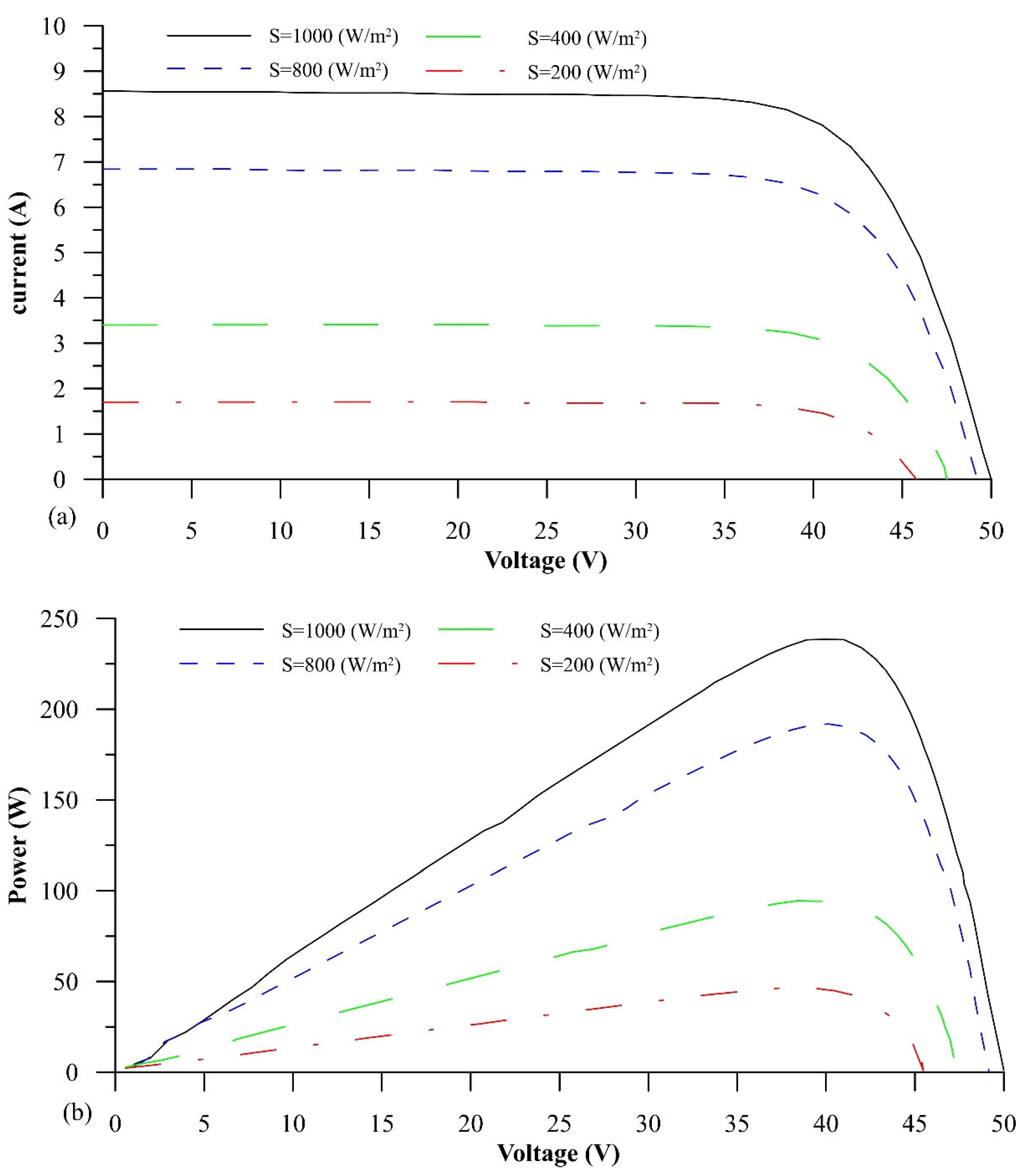
Figure 3a shows that the increase in short-circuit current is proportional to the increase in radiation intensity, whereas the increase in voltage is logarithmically proportional to the radiation intensity. The short-circuit current to near-open circuit voltage is almost independent of voltage and is only proportional to the radiation level. Assuming that the impact radiation to the surface has a constant emission spectrum at constant temperature, the short-circuit current can be used to calculate the amount of impact radiation, and vice versa, because increasing the intensity of radiation at a constant temperature increases the input energy to the system. According to Figure 3, it is natural that the output power increases, which, at a certain voltage, means an increase in electric current; however, due to the current’s dependence on voltage at low voltages, an almost linear relationship between voltage and power is established. In other words, Figure 3a,b confirm each other as well as the physics governing modeling. Furthermore, as the voltage difference approaches the open circuit voltage, the current begins to rapidly decrease, which is a predictable result, and this causes the power to decrease to the point where the value of these two quantities reaches zero in the open circuit voltage.
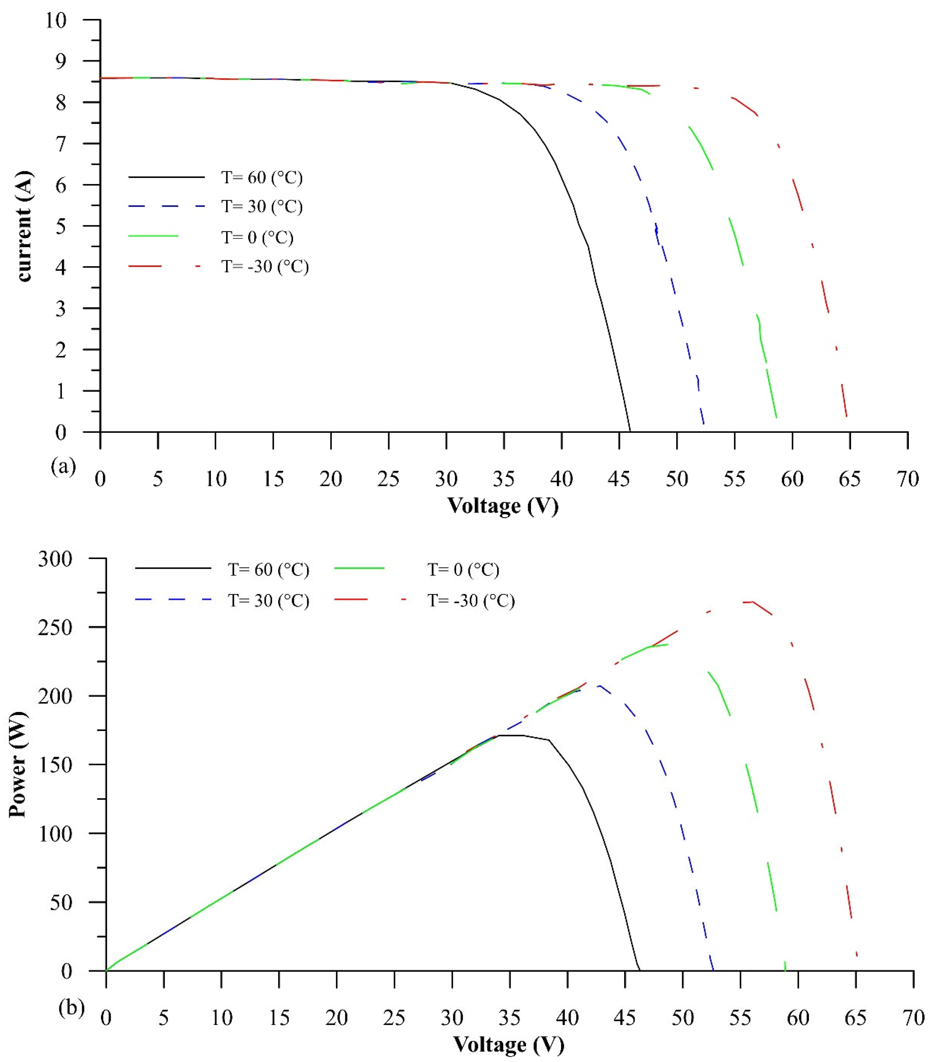
As illustrated in Figure 4a, as the temperature rises, the open circuit voltage falls sharply while the short-circuit current rises slightly. As shown in Figure 4b, the maximum power is reduced to lower voltages due to the rapid decrease in open circuit voltage. The same relationship between open circuit voltage and current to the semiconductor energy gap accounts for this sharp decrease. Similar to Figure 4, it is clear that, at any temperature, a specific voltage is required to achieve optimal power. With a temperature increase of 90 degrees Celsius, this voltage has decreased by about 53%. This diagram also shows that the voltages corresponding to the point of maximum power and the amount of maximum power at different temperatures have a relatively linear relationship.

3.2. Parametric Analysis of the PV/T System and a Discussion of the Results

To compare the models, as well as the various parameters, the operating and climatic conditions are consistent with the data in Table 1.
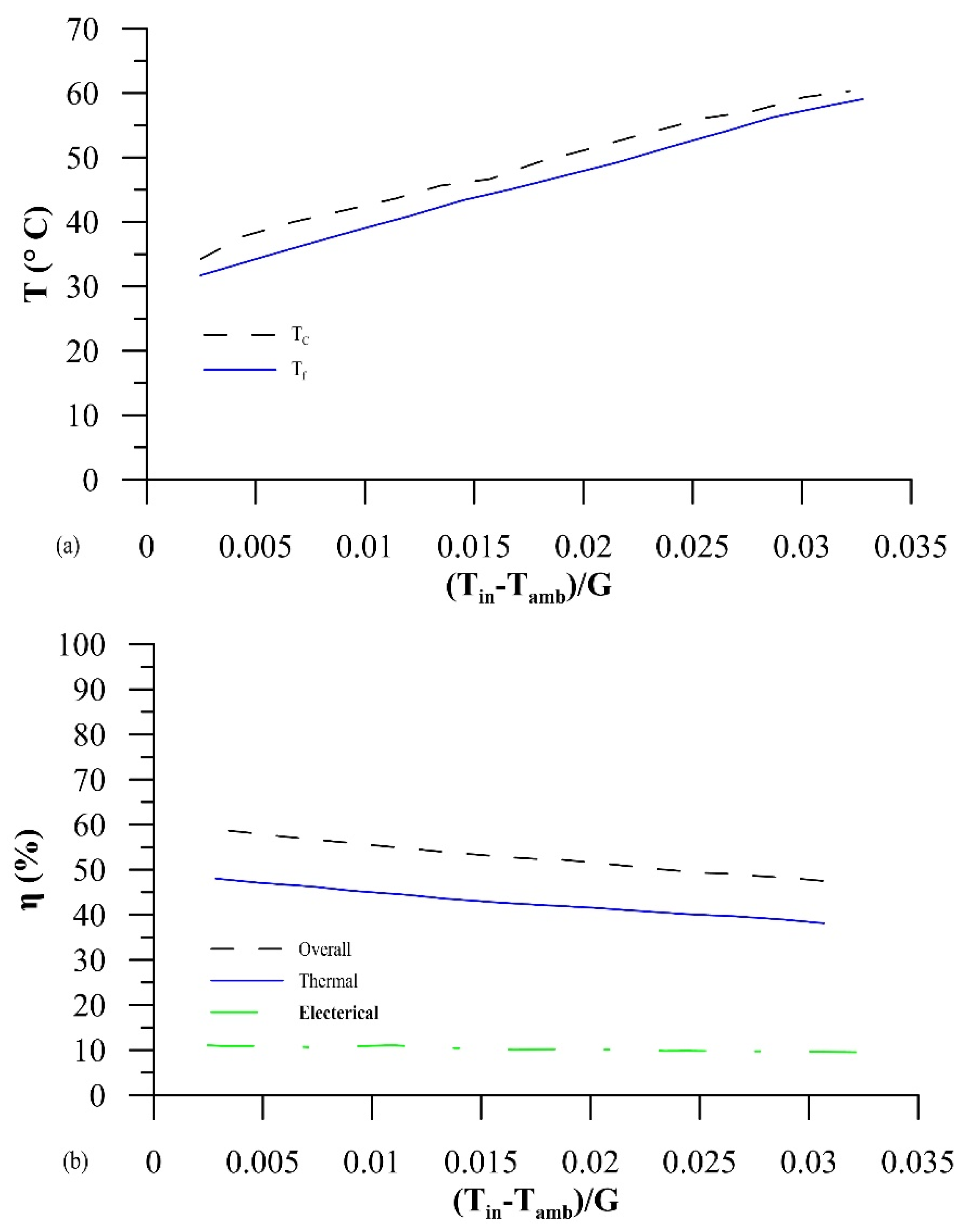
Figure 5a,b show the changes in the outlet water temperature and photovoltaic panel temperature, thermal efficiency, electrical efficiency, and overall efficiency in terms of reduced temperature change. As the temperature decreases, the outlet water temperature and the photovoltaic cell temperature increase by a value of 27%, but the thermal, electrical, and overall efficiencies decrease by a value of 18%.
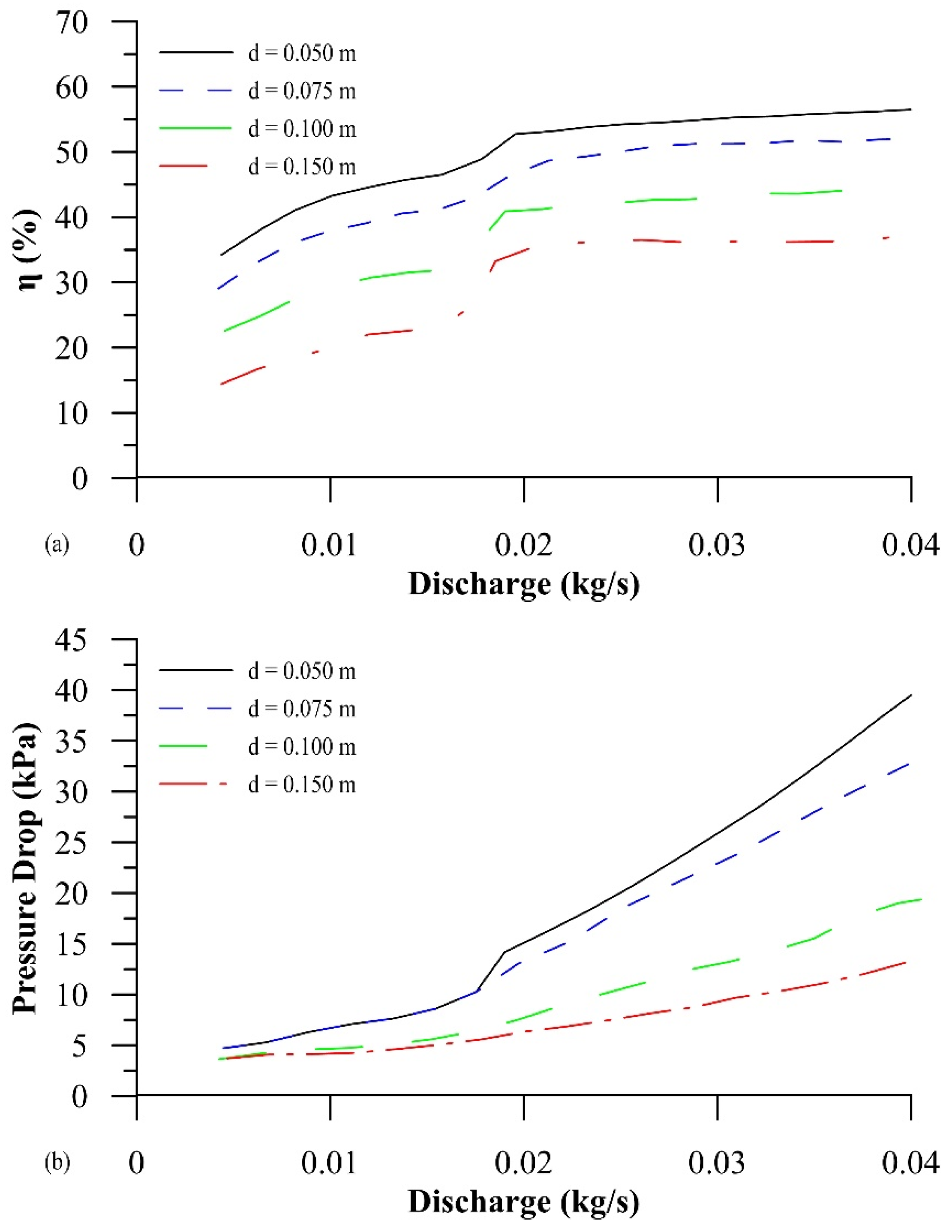
As illustrated in Figure 6a, increasing the amount of reduced temperature has a greater effect on reducing thermal efficiency and thus overall system efficiency. Figure 6b depicts how flow affects the overall efficiency and pressure drop. Assuming a 25 °C inlet water temperature, an increase in flow from 0.005 to 0.016 kg/s increases overall efficiency by 4.4 percent. However, as the flow rate increases from 0.016 to 0.02 kg/s, the overall efficiency rises from 53% to 55%, representing a slight improvement in overall efficiency. The reason for this is that the fluid flow regime is transitioning from a slow to a turbulent state. The flow is in the quiet zone up to the discharge limit of 0.02 kg/s with the diameter of the pipe and the considered inlet water temperature, and it enters the turbulent zone when the flow exceeds the mentioned value, which increases the heat transfer coefficient and efficiency. The heat is concentrated in the turbulent flow.
The fact that helical systems have a turbulent flow at low flow rates and a higher heat transfer coefficient than header-riser models is one of their advantages over header-riser models. Increasing the discharge has little effect on increasing the overall efficiency in the turbulent flow zone. Figure 6b depicts the increase in the pressure drop as the flow increases. The pressure drop in the helical structure increases from 7.5 to 23 kPa as the flow increases in the mentioned range. The discharge rate for pipes with a diameter of 0.0075 m is 0.02 kg/s. The flow is turbulent in this discharge, and the pressure drop is small, so the energy consumed by the pump can be supplied by the electricity generated by the panels.
In Figure 6b, the distance from the center to the center of the pipes is assumed to be 0.1 m, and, thus, the number of pipes is assumed to be constant. With this assumption, the pressure drop decreases as the diameter of the pipes increases.
Figure 7 depicts how the flow and distance between pipes affect the overall efficiency and pressure drop. The overall efficiency decreases from 53 to 37 percent (Figure 7a) as the distance between the pipes increases, and the pressure drops from 47.5 to 13.5 kPa (Figure 7b). The number of pipes in a given area decreases as the distance between them increases. The thermal efficiency of the system decreases as the number of pipes is reduced. Furthermore, by reducing the number of pipes, the length of the pipes and the pressure drop are reduced.
The size of the solar cells is important in determining the distance between the tubes; it is best to pass at least one tube under each solar cell to reduce the temperature of that cell. The overall efficiency increases as the distance between the pipes decreases, but it should be noted that increasing the number of pipes increases the construction cost and increases the pressure drop, thus increasing the pump’s energy consumption. Changes in the overall efficiency and pressure drop caused by changing the two parameters are investigated to better understand the effect of changing the parameters.
At a flow rate higher than 0.016 kg/s, the flow regime is disturbed, and in the distance between the pipes equal to 3.5 and 5.5 cm, the pressure drop reaches more than 15 kPa.
Economic results based on energy sources in different modes are presented in Table 3. As expected, it can be seen that, in the case of a heat source with an open flow and the simultaneous production of power and heat, compared to the case of a heat source with a closed flow, the required primary energy has increased, and this requires energy supply equipment and investment costs. It is more basic; although, in this case, we will have the byproduct of useful heat in addition to the power, but the increase in the initial investment cost will lead to an increase in the total price of the production power. Therefore, it can be seen that, in general, the production power in the open current source mode has a higher cost than the batch current source mode. In addition, according to the methods and technologies used, the cost of producing power using natural gas is lower than that of solar energy, which has more expensive equipment. However, an important issue in this regard is the environmental consequences of using natural gas. No environmental pollutants are produced in the use of solar energy, and this will result in a reduction in external costs. In order to classify solar energy technologies in terms of cost, spiral tubes, photovoltaic panels, and conventional tubes can be mentioned, respectively.

4. Conclusions

The photovoltaic system produced the following results:
  • The average energy efficiency of this panel during the day is 15.29 percent. The greatest instantaneous return value of 12.95 percent and the minimum value of 10.88 percent were calculated during the experiment.
  • This panel’s average exergy efficiency throughout the day is 17.23 percent. Only around 14.5 percent of the energy absorbed from the sun is turned into useable energy, with the remainder being irreversibly wasted, illustrating the inefficiency of the energy conversion process in this panel.
  • Because increasing the intensity of sunlight and decreasing the temperature are the most essential aspects in improving electrical power and efficiency, the optimal working conditions for this solar panel are those with the highest intensity of radiation and the lowest temperature.
  • Because increasing the temperature during the day has a negative impact on energy efficiency and output power, cooling these panels can be regarded as a technique to improve efficiency.
  • A thermal photovoltaic system with a sheet and spiral tube layout has been simulated and parametrically analyzed. The configuration of sheet and helical tubes for the PV/T system of cold water was simulated using a numerical model. As a result of the construction of a MATLAB code, the proposed model with an RMSE = 0.94 is in a good agreement with the experimental data. According to the data, the modeled sample has a thermal efficiency of 43 to 52 percent and an electrical efficiency of 11.5 percent. Parametric analysis was used to assess the state of performance parameters based on control and independent parameters. Changes in overall efficiency and pressure drop are explored in general by adjusting the fluid flow parameters, pipe distance, and pipe diameter. The results show that raising the flow, decreasing the distance between the pipes, and decreasing the pipe diameter all result in an increase in total efficiency. While the pressure drop increases with increasing flow, so does the distance between the pipes and the diameter of the pipes.

Author Contributions

Conceptualization, N.B.K. and N.K.A.D.; Data curation, O.C.; Formal analysis, O.C.; Investigation, A.M.; Methodology, N.B.K.; Project administration, N.K.A.D.; Resources, U.R.; Software, I.P.; Supervision, N.B.K.; Visualization, J.W.G.G.; Writing—original draft, R.S.; Writing—review & editing, M.K. All authors have read and agreed to the published version of the manuscript.

Funding

This research received no external funding.

Data Availability Statement

Not applicable.

Conflicts of Interest

The authors declare no conflict of interest.

References

  1. Maleki, A.; Haghighi, A.; El Haj Assad, M.; Mahariq, I.; Alhuyi Nazari, M. A Review on the Approaches Employed for Cooling PV Cells. Sol. Energy 2020, 209, 170–185. [Google Scholar] [CrossRef]
  2. Karimi, G.; Moradi, Y. Buffer Insertion for Delay Minimization in RLC Interconnects Using Cuckoo Optimization Algorithm. Analog Integrated Circuits and Signal Processing 2019, 99, 111–121. [Google Scholar] [CrossRef]
  3. Molajou, A.; Pouladi, P.; Afshar, A. Incorporating Social System into Water-Food-Energy Nexus. Water Resour. Manag. 2021, 35, 4561–4580. [Google Scholar] [CrossRef]
  4. Khenfer, N.; Dokkar, B.; Messaoudi, M.T. Overall Efficiency Improvement of Photovoltaic-Thermal Air Collector: Numerical and Experimental Investigation in the Desert Climate of Ouargla Region. Int. J. Energy Environ. Eng. 2020, 11, 497–516. [Google Scholar] [CrossRef]
  5. Molajou, A.; Afshar, A.; Khosravi, M.; Soleimanian, E.; Vahabzadeh, M.; Variani, H.A. A New Paradigm of Water, Food, and Energy Nexus. Environ. Sci. Pollut. Res. 2021. [Google Scholar] [CrossRef] [PubMed]
  6. Tiwari, S.; Tiwari, G.N.; Al-Helal, I.M. Performance Analysis of Photovoltaic-Thermal (PVT) Mixed Mode Greenhouse Solar Dryer. Sol. Energy 2016, 133, 421–428. [Google Scholar] [CrossRef]
  7. Abdulrazzaq, A.K.; Plesz, B.; Bognár, G. A Novel Method for Thermal Modelling of Photovoltaic Modules/Cells under Varying Environmental Conditions. Energies 2020, 13, 3318. [Google Scholar] [CrossRef]
  8. Wahab, A.; Khan, M.A.Z.; Hassan, A. Impact of Graphene Nanofluid and Phase Change Material on Hybrid Photovoltaic Thermal System: Exergy Analysis. J. Clean. Prod. 2020, 277, 123370. [Google Scholar] [CrossRef]
  9. Ahmadi, M.H.; Ahmadi, M.A.; Feidt, M. Optimisation Des Performances d’un Cycle de Brayton Irréversible Solarisé à Compressions et Détentes Multiples Sur La Base d’un Algorithme Génétique Multi-Objectif. Oil Gas Sci. Technol. 2016, 71, 2014028. [Google Scholar] [CrossRef] [Green Version]
  10. Ren, X.; Li, J.; Gao, D.; Wu, L.; Pei, G. Analysis of a Novel Photovoltaic/Thermal System Using InGaN/GaN MQWs Cells in High Temperature Applications. Renew. Energy 2021, 168, 11–20. [Google Scholar] [CrossRef]
  11. Ruzzenenti, F.; Bravi, M.; Tempesti, D.; Salvatici, E.; Manfrida, G.; Basosi, R. Evaluation of the Environmental Sustainability of a Micro CHP System Fueled by Low-Temperature Geothermal and Solar Energy. Energy Convers. Manag. 2014, 78, 611–616. [Google Scholar] [CrossRef]
  12. Calise, F.; D’Accadia, M.D.; Vicidomini, M.; Scarpellino, M. Design and Simulation of a Prototype of a Small-Scale Solar CHP System Based on Evacuated Flat-Plate Solar Collectors and Organic Rankine Cycle. Energy Convers. Manag. 2015, 90, 347–363. [Google Scholar] [CrossRef]
  13. Hanifi, K.; Javaherdeh, K.; Yari, M. Exergy and Exergoeconomic Analysis and Optimization of the Cogeneration Cycle under Solar Radiation Dynamic Model Using Genetic Algorithm. In Green Energy and Technology; Springer: Cham, Switzerland, 2018; pp. 1139–1160. [Google Scholar]
  14. Style, R.W.; Peppin, S.S.L.; Cocks, A.C.F.; Wettlaufer, J.S. Ice-Lens Formation and Geometrical Supercooling in Soils and Other Colloidal Materials. Phys. Rev. E-Stat. Nonlinear Soft Matter Phys. 2011, 84, 041402. [Google Scholar] [CrossRef] [PubMed] [Green Version]
  15. Salek, F.; Rahnama, M.; Eshghi, H.; Babaie, M.; Naserian, M.M. Investigation of Solar-Driven Hydroxy Gas Production System Performance Integrated with Photovoltaic Panels with Single-Axis Tracking System. Renew. Energy Res. Appl. 2022, 3, 31–40. [Google Scholar]
  16. Eshghi, H.; Kahani, M.; Zamen, M. Cooling of Photovoltaic Panel Equipped with Single Circular Heat Pipe: An Experimental Study. Renew. Energy Res. Appl. 2022. [Google Scholar] [CrossRef]
  17. Bayrak, F.; Oztop, H.F.; Selimefendigil, F. Effects of Different Fin Parameters on Temperature and Efficiency for Cooling of Photovoltaic Panels under Natural Convection. Sol. Energy 2019, 188, 484–494. [Google Scholar] [CrossRef]
  18. Said, Z.; Arora, S.; Bellos, E. A Review on Performance and Environmental Effects of Conventional and Nanofluid-Based Thermal Photovoltaics. Renew. Sustain. Energy Rev. 2018, 94, 302–316. [Google Scholar] [CrossRef]
  19. Huang, M.; Wang, Y.; Li, M.; Keovisar, V.; Li, X.; Kong, D.; Yu, Q. Comparative Study on Energy and Exergy Properties of Solar Photovoltaic/Thermal Air Collector Based on Amorphous Silicon Cells. Appl. Therm. Eng. 2021, 185, 116376. [Google Scholar] [CrossRef]
  20. Rashidi, M.M.; Mahariq, I.; Murshid, N.; Mahian, O.; Alhuyi Nazari, M. Applying Wind Energy as a Clean Source for Reverse Osmosis Desalination: A Comprehensive Review. Alex. Eng. J. 2022, 61, 12977–12989. [Google Scholar] [CrossRef]
  21. Bandaru, S.H.; Becerra, V.; Khanna, S.; Radulovic, J.; Hutchinson, D.; Khusainov, R. A Review of Photovoltaic Thermal (Pvt) Technology for Residential Applications: Performance Indicators, Progress, and Opportunities. Energies 2021, 14, 3853. [Google Scholar] [CrossRef]
  22. Mohammadnezami, M.H.; Ehyaei, M.A.; Rosen, M.A.; Ahmadi, M.H. Meeting the Electrical Energy Needs of a Residential Building with a Wind-Photovoltaic Hybrid System. Sustainability 2015, 7, 2554–2569. [Google Scholar] [CrossRef]
  23. Rajaee, F.; Rad, M.A.V.; Kasaeian, A.; Mahian, O.; Yan, W.M. Experimental Analysis of a Photovoltaic/Thermoelectric Generator Using Cobalt Oxide Nanofluid and Phase Change Material Heat Sink. Energy Convers. Manag. 2020, 212, 112780. [Google Scholar] [CrossRef]
  24. Mousavi Baygi, S.R.; Sadrameli, S.M. Thermal Management of Photovoltaic Solar Cells Using Polyethylene Glycol1000 (PEG1000) as a Phase Change Material. Therm. Sci. Eng. Prog. 2018, 5, 405–411. [Google Scholar] [CrossRef]
  25. Firoozzadeh, M.; Shiravi, A.H.; Lotfi, M.; Aidarova, S.; Sharipova, A. Optimum Concentration of Carbon Black Aqueous Nanofluid as Coolant of Photovoltaic Modules: A Case Study. Energy 2021, 225, 120219. [Google Scholar] [CrossRef]
  26. Ogbonnaya, C.; Turan, A.; Abeykoon, C. Energy and Exergy Efficiencies Enhancement Analysis of Integrated Photovoltaic-Based Energy Systems. J. Energy Storage 2019, 26, 101029. [Google Scholar] [CrossRef]
  27. Chen, H.; Wang, Y.; Ding, Y.; Cai, B.; Yang, J. Numerical Analysis on the Performance of High Concentration Photovoltaic Systems Under the Nonuniform Energy Flow Density. Front. Energy Res. 2021, 9, 705801. [Google Scholar] [CrossRef]
  28. Bamisile, O.; Huang, Q.; Dagbasi, M.; Adebayo, V.; Okonkwo, E.C.; Ayambire, P.; Al-Ansari, T.; Ratlamwala, T.A.H. Thermo-Environ Study of a Concentrated Photovoltaic Thermal System Integrated with Kalina Cycle for Multigeneration and Hydrogen Production. Int. J. Hydrogen Energy 2020, 45, 26716–26732. [Google Scholar] [CrossRef]
  29. Gupta, N.; Tiwari, A.; Tiwari, G.N. Exergy Analysis of Building Integrated Semitransparent Photovoltaic Thermal (BiSPVT) System. Eng. Sci. Technol. Int. J. 2017, 20, 41–50. [Google Scholar] [CrossRef] [Green Version]
  30. Valizadeh, M.; Sarhaddi, F. Mahdavi Adeli Exergy Performance Assessment of a Linear Parabolic Trough Photovoltaic Thermal Collector. Renew. Energy 2019, 138, 1028–1041. [Google Scholar] [CrossRef]
  31. Siddiqui, O.; Dincer, I. A New Solar Energy System for Ammonia Production and Utilization in Fuel Cells. Energy Convers. Manag. 2020, 208, 112590. [Google Scholar] [CrossRef]
  32. Alobaid, M.; Hughes, B.; O’Connor, D.; Calautit, J.; Heyes, A. Improving Thermal and Electrical Efficiency in Photovoltaic Thermal Systems for Sustainable Cooling System Integration. J. Sustain. Dev. Energy Water Environ. Syst. 2018, 6, 305–322. [Google Scholar] [CrossRef]
  33. Seyedmahmoudian, M.; Mekhilef, S.; Rahmani, R.; Yusof, R.; Renani, E.T. Analytical Modeling of Partially Shaded Photovoltaic Systems. Energies 2013, 6, 128–144. [Google Scholar] [CrossRef] [Green Version]
  34. Nurwidiana, N.; Sopha, B.M.; Widyaparaga, A. Modelling Photovoltaic System Adoption for Households: A Systematic Literature Review. Evergreen 2021, 8, 69–81. [Google Scholar] [CrossRef]
  35. Rosa-Clot, M.; Tina, G.M. Submerged and Floating Photovoltaic Systems: Modelling, Design and Case Studies; Academic Press: Cambridge, MA, USA, 2017; ISBN 9780128123232. [Google Scholar]
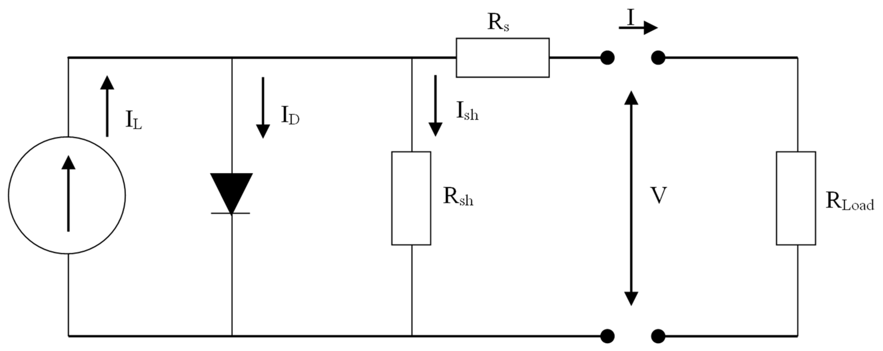
Figure 1. Equivalent circuit of a solar converter.
Sustainability 14 15074 g001
Figure 2. Paging of functional characteristic curves in reference conditions.
Sustainability 14 15074 g002
Figure 3. (a) Current diagram in terms of voltage at different intensities of radiation. (b) Power diagram in terms of voltage at different intensities of radiation.
Sustainability 14 15074 g003
Figure 4. (a) Current diagram in terms of voltage at different temperatures. (b) Power diagram in terms of voltage at different temperatures.
Sustainability 14 15074 g004
Figure 5. (a) Outlet water temperature change and panel temperature change with decreasing temperature η. (b) Change in thermal, electrical, and overall efficiency with decreasing temperature.
Sustainability 14 15074 g005
Figure 6. (a) Change in overall efficiency and pressure drop with flow rate change. (b) Change in overall efficiency and pressure drop with pipe diameter.
Sustainability 14 15074 g006
Figure 7. (a) Change in overall efficiency by changing the flow rate and distance between pipes. (b) Changing the pressure drop by changing the flow rate and distance between the pipes.
Sustainability 14 15074 g007
Table 1. Climate conditions and operating conditions in the parametric analysis.
ParameterValue
Ambient temperature (T)25 °C
Solar radiation (S)1000 W/m2
Wind speed (Vw)1.5 m/s
Inlet water temperature (Tin)30–40 °C
Collector area (A)1.5 m2
Diameter of pipe (d)0.0075 m
Table 2. Economic data of the solar system (the prices do not include VAT).
ItemAssumption
Helical Tube250 ($/m2)
Photovoltaic Panel10,000 ($/kW)
Inverter1200 ($/kW)
Battery120 ($/kW)
Table 3. Cost of generated power based on energy resources ($/kWh) (the prices do not include VAT).
SourceEquipmentPower Cost
Open flow (T = 30 °C)
SolarConventional tube1.074
GasBoiler0.024
Gas & SolarConventional tube & Boiler0.820
SolarHelical tube0.346
Gas & SolarHelical tube & Boiler0.185
Close flow (T = 60 °C)
SolarHelical tube0.345
GasBoiler0.023
Gas & SolarHelical tube & Boiler0.184
Solar Pump
SolarPhotovoltaic System0.44
Publisher’s Note: MDPI stays neutral with regard to jurisdictional claims in published maps and institutional affiliations.