Article

Performance Assessment of Direct Vapor Generation Solar Organic Rankine Cycle System Coupled with Heat Storage

1
School of Mechanical Engineering, Jiangnan University, Wuxi 214024, China
2
School of Energy and Power Engineering, Jiangsu University, 301 Xuefu Road, Zhenjiang 212013, China
3
School of Professional Education & Executive Development, The Hong Kong Polytechnic University, Kowloon, Hong Kong
4
Department of Thermal Science and Energy Engineering, University of Science and Technology of China, Hefei 230027, China
*
Authors to whom correspondence should be addressed.
Sustainability 2022, 14(22), 15296; https://doi.org/10.3390/su142215296
Submission received: 21 October 2022 / Revised: 8 November 2022 / Accepted: 14 November 2022 / Published: 17 November 2022
(This article belongs to the Section Energy Sustainability)

Abstract

:
Phase change materials employed as thermal energy storage can aid in maximizing the use of stored solar energy. The current research examined the impact of three kinds of phase change materials (PCMs) on the dynamic performance of a solar organic Rankine cycle (ORC) system based on a direct vapor production. A number of evacuated flat plate collectors, a condenser, an expander, and an organic fluid pump make up this system. The thermodynamic cycle model of the direct vapor generation (DVG) solar ORC system was combined with the finite difference model of a phase change material heat storage tank created in MATLAB. The effect of PCMs (Organic, Inorganic and Eutectic PCMs) on the collector, ORC, and system efficiency, net power output, PCM temperature, and heat stored was studied weekly, monthly, and annually. Among the selected PCMs, Mg(NO3)2.6H2O had the highest system efficiency at 9.34%; KNO3-NaNO2 had the highest net power output at 33.80 kW; and MgCl2.6H2O stored the maximum energy of 20.18 MJ annually. Under the given operational and boundary conditions, the spring and fall were preferable to the summer and winter months for storing heat from phase change materials.

1. Introduction

Due to the exponential growth of the human population, particularly in emerging nations, the demand for energy per capita is rising at a rapid rate. Consequently, governments are pursuing many potential approaches for effectively using current energy sources. In the recent past, low-grade heat has gained prominence alongside high-grade heat. Solar thermal energy is a viable source of low-grade heat and a potentially appealing alternative. Different researchers have employed several methods, including the Stirling cycle, Kalina cycle [1], trilateral flash cycle [2], Goswami cycle [3], and organic Rankine cycle to collect low-grade heat. Amongst the most promising systems for turning little to moderate thermal energy into power is the organic Rankine cycle (ORC) [4].
The organic Rankine cycle operates similarly to the conventional steam Rankine cycle. In the ORC, a fluid with a high molecular weight and a low saturated boiling temperature is used as a working fluid. Organic fluids having a greater molecular weight than water, resulting in a larger mass flow rate for a similar-sized turbine [5]. As a result, increasing mass flow rate leads to enhanced cycle efficiency. Furthermore, due to its lower boiling temperature, organic fluid is excellent for low-temperature applications [6].
Solar thermal energy is a more recent utilization of the ORC system compared to organic matter, waste heat recuperation, and geothermal sources. It can be a possible source of heat for the organic Rankine cycle since it can drive the ORC at temperatures of around 100 °C or just a little higher [7]. In the past, there have been two types of solar ORC systems reported: indirect and direct solar ORC systems [8]. Commonly known as “conventional solar ORC systems”, indirect solar ORC systems use a heat transfer fluid (HTF) to transmit heat from the solar thermal collectors to the organic fluid in a heat exchanger [9].
However, a transitional heat exchanger is unnecessary in a direct solar ORC system since the organic fluid (two-phase fluid) is passed through the solar thermal collector as an HTF. This means that the solar collector in a direct solar ORC system acts as an evaporator [10]. Recently, there has been a lot of interest in the direct solar ORC system, sometimes referred to as the direct vapor generation (DVG) solar ORC system. Researchers have presented both experimental findings [11,12] and theoretical investigations [13,14,15].
Furthermore, Wang et al. [15] found that employing an organic fluid (R245fa) as an HTF in a flat plate collector may achieve a collector efficiency of up to 55% under normal October weather conditions in Tianjin city. The primary objectives of the researchers were the working fluids selection and the evaluation of system performance [16]. The DVG solar ORC has demonstrated excellent thermal compatibility with varying solar radiation. As a result, its thermal efficiency and net power output are superior to those of a conventional solar ORC system [13].
Solar ORC systems cannot function without solar collectors; they are an essential component [17]. The collectors are characterized as either concentrating or non-concentrating. Concentrating solar collectors only utilize direct solar radiation, whereas collectors that do not focus the solar rays use both beam and diffuse radiation [18]. As a result of the high working pressure inside the collector tube, solar thermal collectors are an important element of the DVG solar ORC system. Therefore, DVG systems may use solar collectors designed for high-pressure operation. The more common parabolic trough collectors (PTC) and evacuated tube heat pipe collectors (EFPC) have competitors in the form of CPC collectors and U-type collectors, as well as evacuated flat plate collectors (EFPCs) [19]. The strong vacuum inside evacuated flat plate collectors allows them to operate at over 50% efficiency, even when heated to temperatures over 200 °C. These collectors may operate at extremely high operating pressures with great efficiency. Unlike focusing type collectors, the collector may employ diffuse irradiation without the necessity of a tracking system [20]. This is why DVG solar ORC systems favor non-tracking, non-concentrating and less-cleaning solar collectors [21,22].
Intermittent solar radiation can impair the process of generating electricity. Consequently, the DVG solar ORC system is often kept operational by using thermal energy storage [23]. It is challenging and time-consuming to choose the ideal heat storage for thermal power generating systems. Latent heat storage (LHS) and sensible heat storage (SHS) are two forms of thermal storage that have been described in the past [24]. One form of LHS is phase change material (PCM) storage. This type of thermal storage has shown promise and efficiency because of its greater energy density in comparison with SHS. PCMs have a 5–14× greater energy density per volume than SHS [25]. Moreover, they are useful, since the maximal energy storage happens at constant temperatures. Conversely, they pose substantial drawbacks, such as poor heat transmission, subcooling, and flammability etc., [26].
There are three distinct forms of phase transitions of PCMs: solid—liquid, liquid—gas, and gas—liquid [27]. The primary categories are organic, inorganic, and eutectics, which are split into organic, inorganic, and eutectics. PCMs have a variety of advantages and disadvantages depending on their categorization [19]. For instance, the organic PCMs are preferred due to their chemical stability at high temperature and pressure, low susceptibility to corrosion and sub-cooling, high compatibility with a variety of container types, and broad temperature accessibility. They do, however, have the drawbacks of being very flammable, having poor heat conductivity, and having larger changes in volume.
However, the inorganic PCMs have several benefits, including excellent thermal conductivity, low cost, little volume change, and zero flammability. A few disadvantages of inorganic PCMs are their incompatibility with micro- and nano-capsulation procedures, the high degree of sub-cooling, and corrosivity. The thermal conductivity, energy density, and the sharpness of the phase transitions in eutectic PCMs are all noteworthy. PCMs of this kind, on the other hand, are rare and costly [28,29]. Low-temperature PCMs have a melting point below 60 °C, whereas medium-temperature PCMs fall between 60 °C and 150 °C, and high-temperature PCMs melt at temperatures higher than 150 °C. [25]. For the solar ORC system, PCMs with a modest temperature range are often appropriate.
PCMs and solar power plants together provide a realistic option [30]. Abbasi et al. [28,31] investigated the exergo-economic performance of a solar thermal power generation with PCMs. It has been demonstrated that the use of PCMs resulted in the power plant functioning continuously. The levelized cost of electricity (LCOE) from concentrated solar systems has been trending downwards. This research has focused on identifying methods to decrease thermal resistance between the heat transfer fluid and the PCM in order to boost heat extraction rates [32].
A 100 kilowatt solar ORC system with solar salt PCM storage was analyzed [33,34]. Aluminum fins significantly reduced the temperature gradient inside the PCM storage tank. Alvi et al. [35] investigated and compared indirect and direct solar ORC systems based on PCM. The thermal reactivity of PCM with the organic fluid was discovered to be substantially greater than that of PCM with water. In contrast to the direct system, the indirect solar ORC system has a higher energy density per unit volume.
The majority of prior research on solar ORC systems integrated with PCMs has been on modeling, simulation, and performance assessment. In addition, most studies relied on an indirect solar ORC system. However, there is a lack of research on how different organic, inorganic, and eutectic PCMs influence the DVG solar ORC system. This research is one of a kind, since it compares the performance of the DVG solar ORC system with three distinct PCMs. Some additional input comprises:
The PCM storage tank model was developed and validated in the MATLAB programming environment using the finite difference approach.
Weekly, monthly, and annual simulations of the PCM integrated DVG solar ORC system were carried out.
The measurement and comparison of net power output, as well as the quantity of heat stored, were carried out.
DVG solar ORC systems with PCM storage will be able to be compared to the results of this study as they advance in the research field. The system’s performance will guide design engineers to select the best phase change materials for use in specific applications.

2. The Overall System Layout

Figure 1 depicts the layout of the proposed DVG solar ORC system. The suggested system is comprised of a number of evacuated flat plate collectors (EFPCs), a tank for phase change materials, a pump for an organic fluid, a condenser, a turbine, and a generator. The EFPC array serves as an evaporator (direct vapor generator) in the current configuration. The PCM storage tank has two modes of operation: discharging and charging. Additionally, the fundamental solar ORC system is taken into consideration, which does not need a sophisticated control scheme.
If the PCM temperature is lower than the evaporation temperature (Tevp > Tpcm), the system enters the charging mode.
If the evaporation temperature is less than the PCM temperature (Tevp < Tpcm), the system enters the discharging mode.
The whole process is comprised of expansion, condensation, pressurization, and evaporation. The organic fluid is first warmed up in a network of EFPCs to the appropriate evaporation temperature. Solar radiation heat is captured by the collectors, who then transfer it to the organic fluid. After entering the PCM storage tank, the working fluid either releases heat during discharge or takes it in during charging, depending on the mode. After entering the expander in a saturated vapor phase, the working fluid produces power while lowering the pressure. It is then cooled to the subcooled liquid state in the condenser. The organic fluid is then transferred back to the solar collectors by pressurizing it in the organic fluid pump.
It was presumed that the organic fluid’s temperature did not change as it moved through the tube. Consequently, the fluid’s temperature loss across the tube is insignificant. Throughout this process, it was expected that the tube’s inner wall would be at an isothermal temperature. The exterior surface of the working fluid tube is a component of the PCM interface. Additionally, a linked boundary condition indicating the variation in the outer surface temperature was chosen to represent the PCM. Whether the system is in discharging or charging mode, each of the five valves opened or closed accordingly. In addition, to aid the reader’s comprehension, the color red was used to represent a closed valve and the color blue to represent an open valve. Arrow signs are placed to show the direction of flow in both modes. Valves V2, V3, and V5 were left open during charging, while V1 and V4 were closed. During the discharge phase, all the valves except V4 were closed.
The data were imported into MATLAB in order to conduct a dynamic simulation of a DVG solar ORC system coupled with PCM storage. The system was expected to begin functioning when solar radiation at the collector’s surface approaches 400 W/m2. The system instead powered down or entered a discharge mode. The PCM was kept at a temperature 10 °C below its melting point. This demonstrated that the PCM started off the simulation in its solid form, uncharged. The storage tank’s discharge limit was kept at a temperature 20 °C below the PCM’s melting point, enabling the system to discharge the storage within a reasonable temperature range.
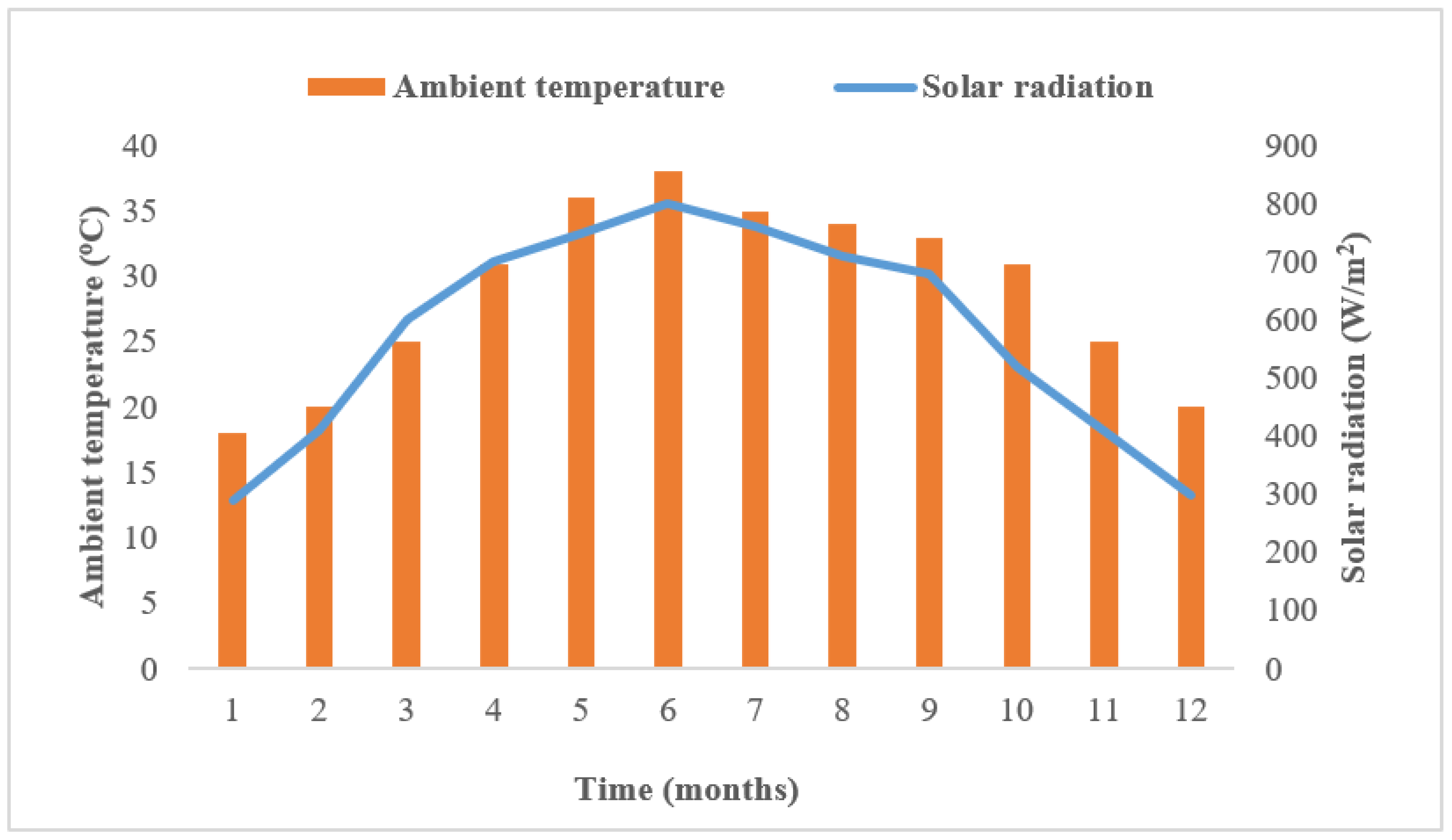
The present research made use of Lahore, Pakistan’s hourly climate data. Data for Lahore’s typical meteorological year (TMY) were produced using the Meteonorm program [36]. Both the average monthly temperature and the average amount of solar radiation are shown in Figure 2. Maximum solar radiation and ambient temperature are both seen to occur in June, whereas the minimums occur in January.

3. Modeling Based on Thermodynamics

3.1. Solar Radiation

The formula [22] was used to determine how much sunlight the solar collector’s sloping surface received. The tilt of the solar collectors was the same as Pakistan’s latitude at Lahore.
G t = ( G b + G d G b G h ) R b + I d ( 1 G b G h ) ( 1 + cos β 2 ) ( 1 + G b G h Sin 3 ( β 2 ) ) + G h ρ g ( 1 cos β 2 )

3.2. Thermal Solar Collectors

The solar ORC system with direct vapor production used evacuated flat plate collectors. At high working temperatures, the EFPCs are useful because of their high efficiency. They are helpful due to the fact that they are non-concentrating, non-tracking, and static. In addition, they employ both dispersed and direct radiation, which makes them advantageous in regions with limited sun resources [21]. A thermal gradient equation is often used to determine a solar collector’s thermal efficiency.
η c l ( T ) = η c l , 0 A G ( T T a m b ) B G ( T T a m b ) 2
The solar thermal collectors with an optical efficiency of 0.774 have a primary heat loss coefficient A of 0.376 Wm−2 °C−1 and an additional heat loss coefficient B of 0.006 Wm−2 °C−2 [19]. The collector’s performance can be impacted if fluid is subjected to a phase shift while in the thermal collection process. However, this effect was ignored in the present research. Because of this, two-phase fluid was acceptable for use in the solar collector. The efficiency of a single, commercially accessible unit with a surface area of between 1–2 m2 is often determined using the Equation (2). When hundreds of square meters are involved, the temperature differential between nearby solar collectors is negligible. This implies that the collector’s typical temperature may differ from one module to the next. The array of collectors contains an organic fluid in both its vapor and liquid states. Throughout the whole binary state, the average collector temperature remains stable. Thus, Equation (2) may be used to ascertain the collector efficiency. The temperature of the collector fluctuates depending on where it is in relation to the liquid. Equation (3) can be used to compute the collector’s surface area.
S l = T f , i T f , o m f C p , f ( T ) η c l ( T ) G d T
An approximate first-order calculation may be used to determine an organic fluid’s thermal heat capacity.
Using Equations (2)–(4) the solar collector area may be calculated by putting a 1 = A / G , a 2 = B / G
C p   ( T )   =   C p , 0   +   a   ( T     T 0 )
S l = m f c 2 G ( θ 2 θ 1 ) [ ( C p , a + α θ 1 ) ln ( T f , o T a m b θ 1 ) T f , i T a m b θ 1 + ( C p , a + α θ 2 ) ln θ 2 T f , i + T a m b θ 2 T f , o + T a m b ]
The arithmetic solutions to Equation (6) are, where, and. θ 1 and θ 2 when θ 1 < 0 , θ 2 > 0 .
η o a 1 θ a 2 θ 2 = 0
C p , a = C p , 0 + α ( T a m b T 0 )
The efficiency of solar thermal collectors in the liquid state may be calculated using
η c l , l = m f ( h l , o h l , i ) G S l
Using Equations (9) and (10), the efficiencies of solar collectors with organic fluid in the vapor state and the whole collector array are computed, respectively.
η c l , v = m f ( h b , o h b , i ) G S b
η c l = m f ( h b , o h l , i ) G ( S l + S b )

3.3. Thermal Storage Tank

Figure 3 illustrates the architecture of the PCM-filled double-pipe heat exchanger. As indicated in portion (a) of Figure 3, the multi-tubes are merged into the large cylinder shell. Moreover, as illustrated in portion (b) of Figure 3, each tube comprises of a mini-tube contained inside a bigger tube. PCM is injected into the larger cylinder while the organic fluid is pumped through the smaller cylinder. The length of each tube stays unchanged. The fluid tube’s diameter is maintained to be 10 times smaller than that of the PCM tube [35]. The PCM tank is estimated to have a capacity of 90 m3. The PCM tube and the containers outside surface need to be insulated. Depending on operational circumstances, the thermal storage tank runs in a discharging or charging mode. The transfer of heat between PCM and organic fluid is accomplished by convection. However, it is considered that heat transport inside PCM occurs by conduction. The organic fluid transfers heat to the PCM as it is charging. PCM’s melting point is reached when its temperature rises from its solid state. The PCM’s temperature stays constant during the remainder of the melting process. When the melting process is finished, the PCM transforms into a liquid state.
During the discharging phase, heat is transmitted from PCM to working fluid. By dissipating heat into the organic fluid, the PCM changes state from liquid to solid [37,38]. The PCM storage tank is modeled using the renowned Enthalpy approach. To create the mathematical model for heat transfer via PCM, the following inferences are drawn:
  • Conductive heat transmission is regarded as the PCM’s predominant mechanism;
  • One-dimensional heat transmission is considered;
  • During each condition, the thermophysical parameters of the PCM stay constant;
  • Natural convections may occur owing to density differences, which were disregarded by this model.
ρ H t = κ   p c m 2 T p c m y 2
where “H” represents the total volumetric enthalpy. It is the total of PCM’s latent and sensible heat at a certain temperature [39]. As a result, the Equation (12) allows for the determination of the total volumetric enthalpy of PCM at any given temperature.
H = T m T ρ p c m C p c m d T p c m + ρ p c m L F ( λ )
The PCM’s latent heat is correlated with its density and liquid fraction (“LF”), respectively [40]. The liquid fraction LF must be determined in order to determine the latent heat of the PCM. As a result, LF can be determined using the relation below.
L F = { 0           f o r             T p c m < T m           S o l i d   r e g i o n 1         f o r           T p c m > T m           L i q u i d   r e g i o n    
Whether a PCM is liquid or solid is indicated by its LF value. When LF equals 0, PCM is in the solid phase. However, if LF = 1, it is assumed that the PCM is in the liquid area. Furthermore, Equation (14) allows for the calculation of the PCM’s sensible enthalpy.
h ( T ) = T m T ρ p c m C p c m d T p c m
From Equations (11) and (13), the PCM enthalpy may be calculated as follows:
H = { ρ p c m C p c m ( T p c m T m )                                           f o r             T p c m < T m           S o l i d   r e g i o n ρ p c m C p c m ( T p c m T m ) + λ ρ p c m           f o r           T p c m > T m           L i q u i d   r e g i o n
If the PCM is in a solid area, as shown by Equation (15), it carries solely sensible heat. On the other hand, if the PCM is in a liquid phase, there is both latent and sensible heat available. With the help of Equation (16), we see that the PCM’s temperature, “Tpcm”, can be derived from the PCM’s volumetric enthalpy [29].
T p c m = { T m + H ρ p c m . C p c m f o r H < 0 T m f o r 0 < H < ρ p c m . λ T m + H ( ρ p c m . λ ) ρ p c m . C p c m f o r H > ρ p c m . λ
PCM’s latent heat is denoted by λ and density of PCM ρpcm is given by Equation (10). In order to determine one-dimensional heat flow inside the PCM could be rewritten as follows using Equations (12) and (13).
h t = y ( α h y ) ρ   p c m λ ( L F t )
In addition, as shown in Equation (18), the amount of heat retained by the PCM is calculated by multiplying the PCM’s total mass by the disparity in specific enthalpy between the PCM’s terminal and terminal nodes [27].
Q s t = M p c m ( h mx h i n )
In a similar fashion, discharge heat is determined by multiplying the specific enthalpy difference between the first and last nodes of the storage tank by the entire mass of the PCM, as per Equation (19).
Q r e l = M p c m ( h i n h m x )
Using Equation (20), the entire mass of PCM can be estimated.
M p c m = π ( r p c m 2 r f l u i d 2 ) × L p c m × ρ p c m
In this equation, the density is denoted by ρ , and r stands for the radius. Using the finite difference technique and the MATLAB simulation tool, an accurate model of the PCM storage tank was developed and then compared to experimental data published in academic journals. Afterwards, the PCM model was integrated with the solar ORC system. Table 1 displays the thermophysical characteristics of the PCMs employed in this investigation.

3.4. PCM Model Validation

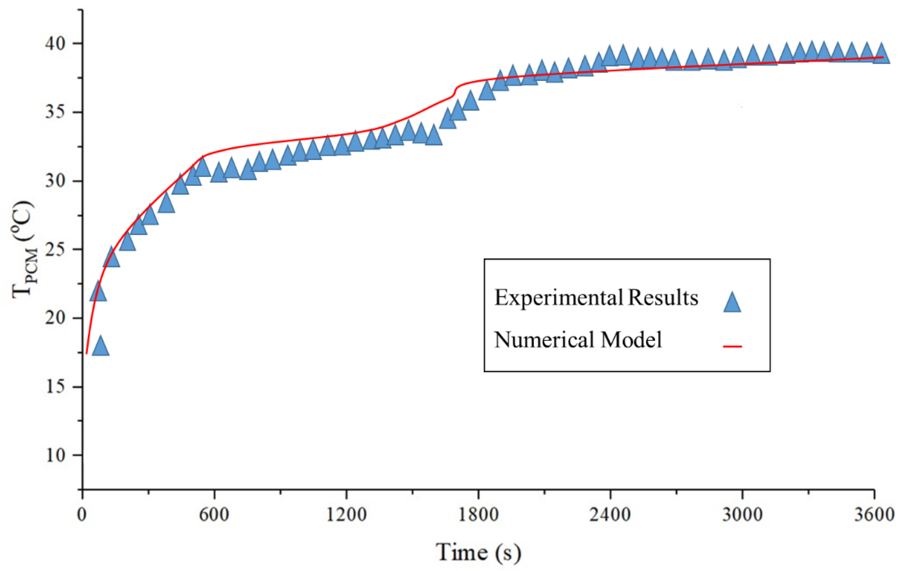
The current numerical model was experimentally validated by comparing the findings of the Lacriox [41] experiment with those of the numerical simulation. Two concentric tubes, one 0.0127 and the other 0.0258 mm in diameter, made up the unit’s storage capacity. Each tube was 1 m in length. The outside tube has superior insulation. PCM was used to fill the inter-tube spaces. Water was utilized to fill the inner tube so that it might serve as a heat exchanger (HTF). The heat transfer fluid maintained a constant mass flow rate of 0.0315 kg/s. The used PCM (n-octadecane) has a melting point of 28.2 °C. Comparing experimental outcomes to those anticipated by this model constitutes validation. Figure 4 demonstrates that the experimental and numerical findings are in excellent agreement. Table 2 displays the thermophysical characteristics of PCM n-octadecane.

3.5. Organic Rankine Cycle

Due to its cheap cost, simple technical requirements, and usefulness in low-to-medium temperature applications, the fundamental and subcritical ORC was investigated in this work. It was assumed that evaporation and condensation are isobaric processes, whereas expansion and pressurization are adiabatic. Table 3 lists the assumptions and operating conditions examined for this investigation.
Using Equations (21) and (22), the power created by the expander and the power utilized by the pump were examined, respectively.
w t = m f ( h t , i h t , o )
w p = m f ( h p , o h p , i )
The expander and pump isentropic efficiencies were obtained using Equations (23) and (24) respectively.
ε t = h t , i h t , o h t , i h t , o s
ε p = h p , o s h p , i h p , o h p , i
os represents the ideal thermodynamic process. To calculate how much energy is required to perform the heating operation of an ORC, the rise in enthalpy of the working fluid from the pump to the expander, multiplied by the mass flow rate of the organic fluid.
q = m ( h t , i h p , o )
As demonstrated in Equation (26), The efficiency of an ORC may be estimated by dividing the net power produced by the heat input.
η O R C = w t ε g w p q
The DVG solar ORC system’s overall system efficiency can be estimated using
η s y s = η O R C η c l

3.6. A Suitable Organic Fluid for the DVG Solar ORC System

Various parameters, including as flammability, toxicity, cycle efficiency, and different environmental issues (GWP and ODP), are used to identify the fluid that works well in the solar ORC system [7]. Choosing the appropriate organic fluid for a solar ORC system is a difficult and critical undertaking. In addition, the DVG solar ORC system becomes more sophisticated because of its constraints, such as its heightened sensitivity to environmental conditions, and increased operating pressure and temperature.
R123 is commonly acknowledged as a viable fluid used in organic Rankine cycle (ORC) devices at low temperatures; nonetheless, there is no perfect or optimal operating fluid. R123 has a fair condenser and evaporator pressure, is harmless to use, has no ODP, but has a GWP, enabling the seek for a low-temperature fluid with greater performance [11].

4. Results and Discussions

In this section, the outcomes of dynamic MATLAB simulations of solar ORC systems are shown, analyzed, and debated. A 1-h time step is used for the duration of the simulation. Lahore is selected as a reference point with coordinates of 31.5204° N and 74.3587° E. In order to assess the efficiency of a PCM-based DVG solar ORC system, year simulations are run. First, simulations are conducted for the coldest and warmest weeks of the year. On the coldest week, ambient temperature and solar radiation (G<400 W/m2) are quite low. Therefore, the energy provided by the solar collector array is insufficient to power the PCM storage tank. Under such conditions, the suggested system is inoperable. Therefore, the performance of the whole system on the week with the lowest temperature and solar radiation was not discussed in this study.
Then impact of three different types of PCMs on overall system efficiency and net power output were also analyzed and compared. Moreover, the amount of heat stored by PCM was also examined.

4.1. During the Warmest Week, PCM-Based DVG Solar ORC System’s Dynamic Performance

4.1.1. Changes in the Temperature of PCMs and the Amount of Solar Radiation over Time

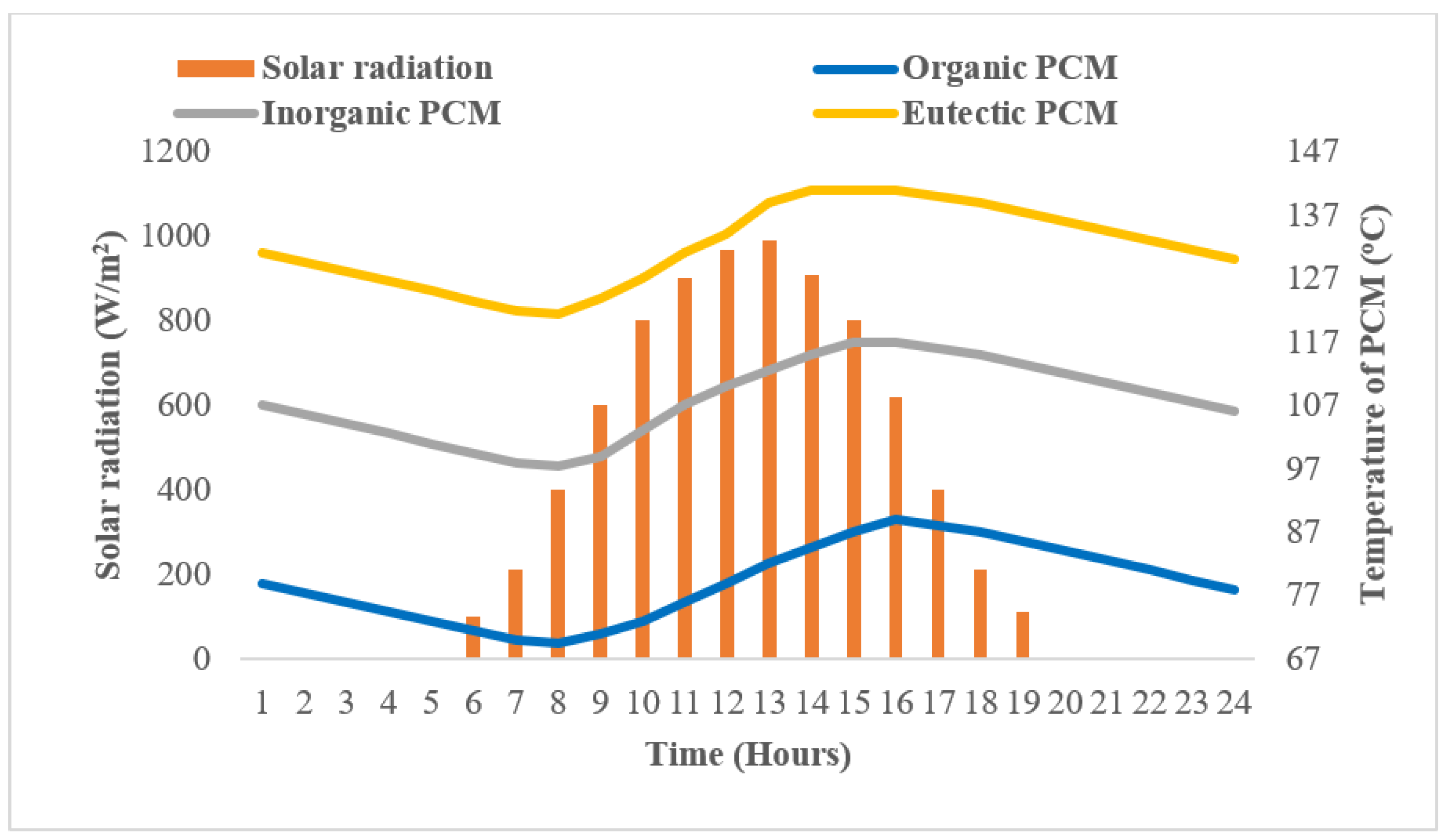
Three different types of PCMs were selected to compare the storage tank’s dynamic performance. Figure 5 depicts the evolution of PCMs solar radiation and temperature over time. The PCM’s initial temperature was set 10 °C below its melting point. The PCM temperature reduces until 8 a.m., then increases until 4 p.m., and then declines again till midnight. In addition, it was determined that PCM storage was adequate for the system to operate for a whole day.
Moreover, time required by eutectic, organic and inorganic PCM was found to be 6, 7 and 8 h, respectively, depending on the operational and boundary circumstances. This might be because of higher thermal conductivity of eutectic PCM in comparison with others.

4.1.2. Collector and ORC Efficiencies Variation over Time

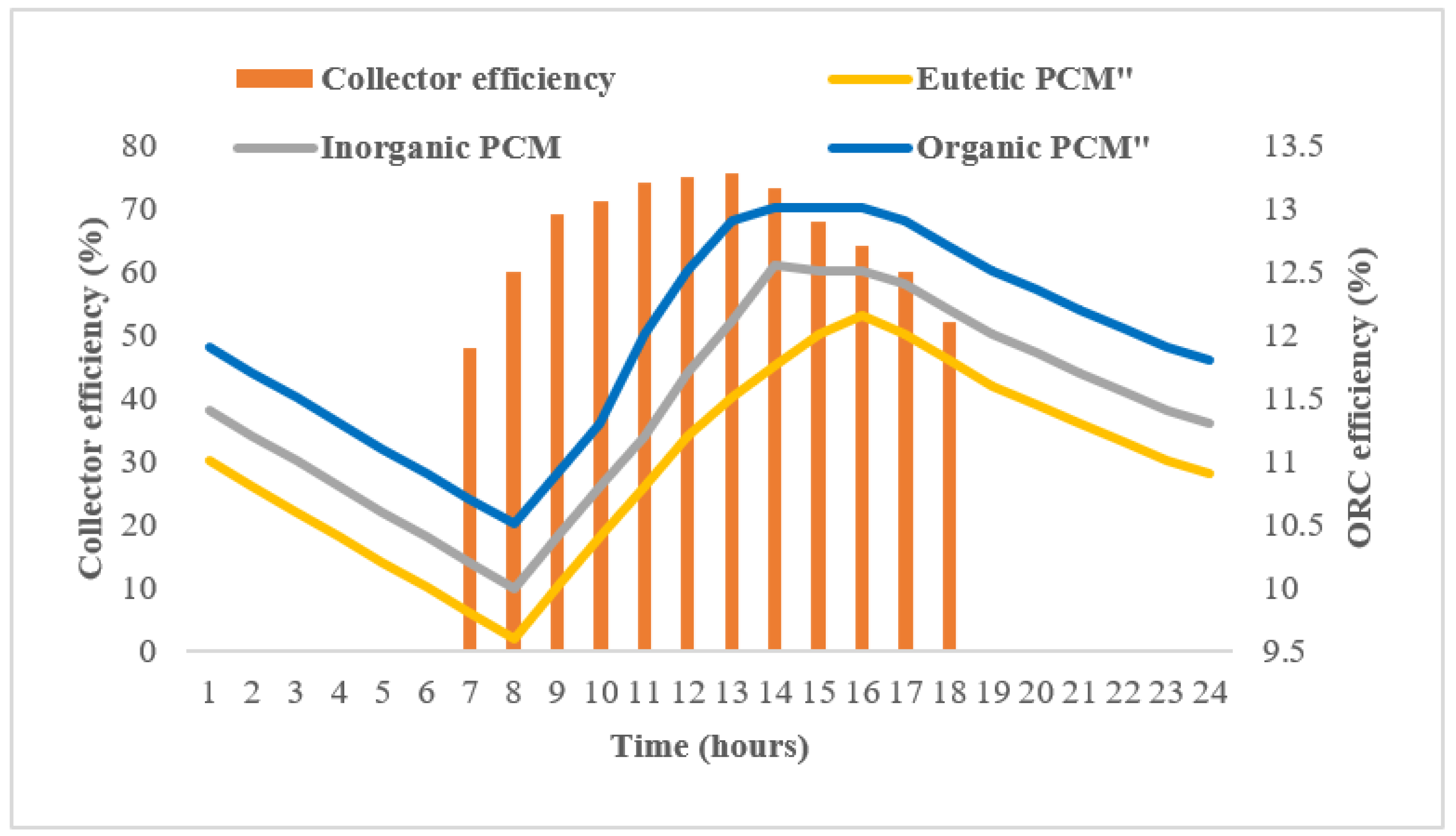
The characteristics that directly affect the system’s overall performance are the collector and ORC efficiency. Hence, it is essential to evaluate the effect of PCM on collector and ORC efficiency. Figure 6 depicts the variations in collector and ORC efficiency. The ORC efficiency was found to be in the 10% to 13% range. The efficiency of solar collectors, on the other hand, lies between 48% and 75%. As a result, the DVG solar ORC system is able to operate for 24 h straight.
Moreover, ORC efficiency exhibited by eutectic, organic and inorganic PCM was found to be directly related to their melting point temperature at given operating and boundary conditions. Hence, organic PCM showed higher ORC efficiency as compared to others.

4.2. Performanceof the System over the Month

4.2.1. Variation in Collector and ORC Efficiency on Annual Basis

The daily average monthly ORC efficiency and collector efficiency of three different PCMs are depicted in Figure 7. Observations revealed that both parameters (collector efficiency and ORC efficiency) climb and fall when solar radiation and ambient temperature increase and drop. The highest ORC efficiency and collector efficiency output are seen during the hottest month of June. In contrast, these levels are lowest in January, which is the chilliest month. It was demonstrated that ORC efficiency remains in the 6.5% to 13.5% range. On the other hand, the efficiency of solar collectors remains between 74% and 77.5% at given operating and boundary conditions.
ORC efficiency of the eutectic, organic, and inorganic PCM was found to be directly correlated with melting point temperature under specific boundary and operating conditions. In general, the ORC efficiency falls as the melting point temperature rises for a fixed evaporation temperature. Because of this, organic PCM exhibited a better ORC efficiency than other PCMs.

4.2.2. Variation in System Efficiency on Annual Basis

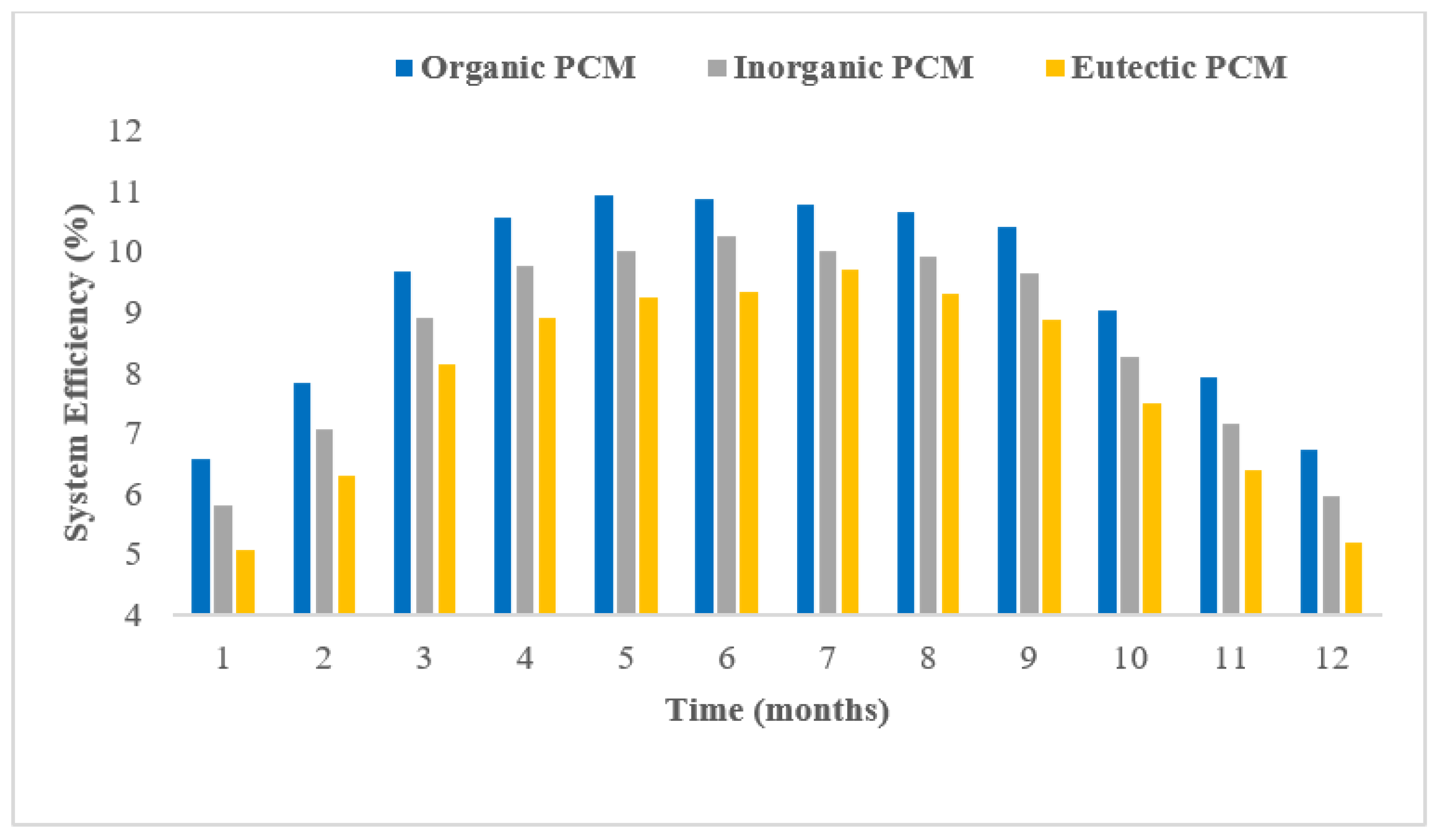
Figure 8 shows how three distinct types of PCMs’ total system efficiency changed on a daily average monthly basis. By comparing Figure 3 and Figure 8, it can be seen that the overall system efficiency increases and decreases when solar radiation and ambient temperature rises and declines. Consequently, system efficiency exhibited comparable behavior, as observed in a weekly simulation. The highest system efficiency was seen during the hottest month of June. In contrast, these levels were lowest in January, which is the coolest month. The overall system efficiency lies in the range of 4 to 11% at specific boundary and operating conditions.
Under specified operating and boundary conditions, eutectic, organic, and inorganic PCMs system efficiency was found to be directly associated with the melting point temperature. The overall system efficiency has shown decreasing trend with increase in melting point temperature. Due to this, organic PCM demonstrated superior system efficiency compared to other PCMs.

4.2.3. Variation in Net Power Output on Yearly Basis

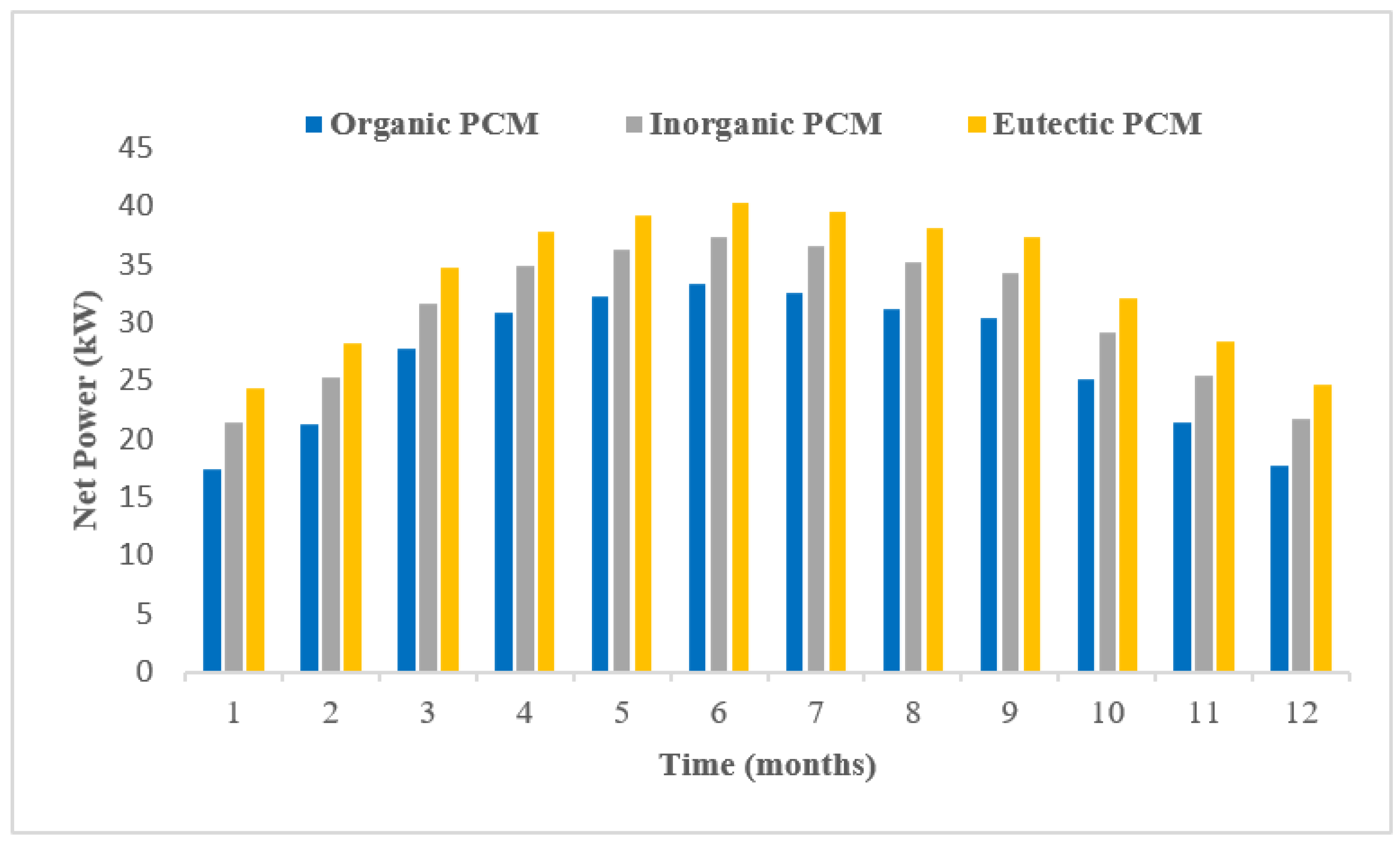
Figure 9 displays the daily average monthly change in the net power output of three distinct PCM types. Comparing Figure 3 and Figure 9 demonstrates that the net power output increases and decreases as solar radiation and ambient temperature increase and decrease, respectively. As demonstrated by a weekly simulation, the net power output has exhibited comparable behavior. During the hottest month of June, the net power output is at its peak. In contrast, these levels are lowest during the coldest month of January. Under specified operating and boundary circumstances, the net power output falls between 17.4 kW and 40.4 KW.
Under defined operating and boundary conditions, it was found that the net power output of eutectic, organic, and inorganic PCMs is linearly proportional to their melting point temperatures. As a result, the eutectic PCM has greater net power output compared to other PCMs.

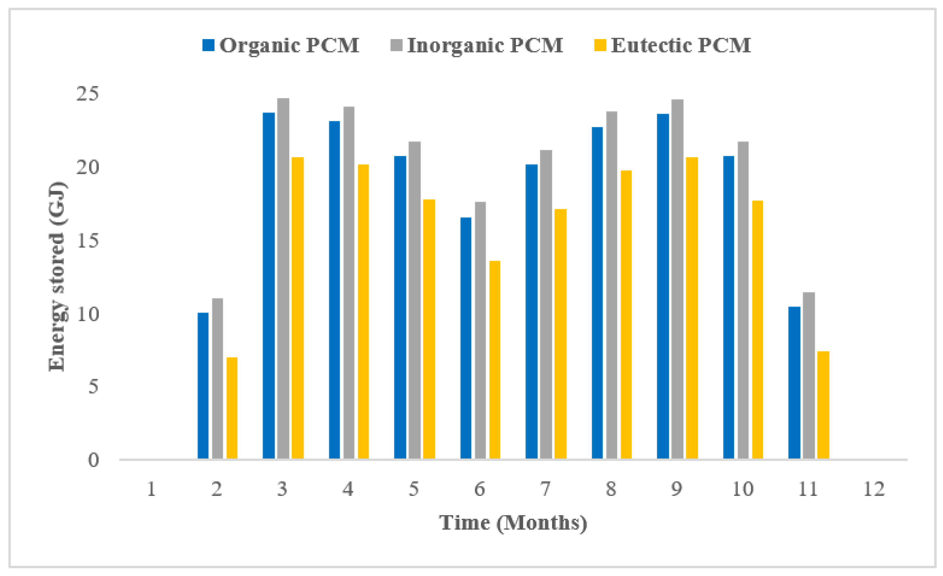
4.2.4. Variation Energy Stored on Annual Basis

One of the most important metrics by which PCM storage performance may be evaluated is the quantity of energy it can hold. The storage tank is constructed to operate at the PCM’s melting point. The entire quantity of energy retained by PCM, however, comprises both sensible and latent heat. Figure 10 displays the daily average monthly amount of energy conserved by PCM in the DVG solar ORC system. The amount of energy retained by PCM is independent of changes in solar radiation and ambient temperature, contrasting collector, ORC, and system efficiency. December and January have no energy stored, since solar radiation is so low during these months. Since the working fluid temperature does not rise beyond the PCM temperature during these months, there is no heat transfer between the two.
In June, solar light and accessible heat are at their peak, but the PCM stores very little energy. When solar radiation and ambient temperature are quite high, the organic fluid evaporation temperature of reaches near its critical point temperature. When the working fluid’s evaporation temperature gets close to its critical point temperature, the working fluid’s thermal conductivity drops considerably, which has further consequences on heat transmission between the PCM and the working fluid. If we take R123 as an example, at 2 MPa and 100 °C, its thermal conductivity is 0.068 Wm−1K−1, but at 180 °C, it drops to 0.0205 Wm−1K−1. Finally, R123’s thermal conductivity decreases more than three times from 100 to 180 °C (approaches its critical point temperature of 183.68 °C) as the evaporation temperature increases. As a consequence, the amount of energy that can be stored between R123 and PCM lowers dramatically.

5. Conclusions

A solar ORC system with direct vapor generation based on phase change materials was examined. Heat was transferred to the system via a set of evacuated flat plate collectors. The PCM storage tank was connected to the system for stable power production. To duplicate discharging and charging mode, the complete system was modeled in MATLAB. The duration of the simulation was maintained at one hour throughout the simulation process. Weekly, monthly, and yearly simulations were run to assess the efficacy of the PCM-based DVG solar ORC system.
The effects of three different kinds of PCMs (organic, Inorganic and eutectic PCMs) on collector, ORC, system efficiency, PCM temperature, net power output, and stored energy were analyzed on a weekly, monthly, and yearly basis.
The system efficiency decreased when melting point temperature moved closer to the critical point temperature of the working fluid under the given operating and boundary conditions. Conversely, the net power output increased with an increase in the melting point temperature of the PCM.
Each of the three chosen PCMs showed superior performance in some aspects of the performance assessment, but none of them have done so across the board. For example, organic PCM achieved the highest system efficiency (9.34%) among the chosen PCMs, while eutectic PCM had the highest net power production (33.8 kW), and the inorganic PCM stored a maximum of 20.18 MJ on an annual basis. Consequently, by adopting a more complicated control method and PCM storage, system performance can be enhanced even more.

Author Contributions

Conceptualization, J.Z.A.; methodology, J.Z.A., M.A. and Y.J.; writing—original draft preparation, J.Z.A. and Y.J.; revision and final editing, Y.F., G.P. and W.Q. All authors have read and agreed to the published version of the manuscript.

Funding

This research work has been supported by the Jiangsu provincial government research funding, China (2021K101B) and national postdoctoral science foundation of China. The work described in this paper was partially supported by the Research Grants Council of the Hong Kong Special Administrative Region, China (Project No.: UGC/IDS(R)24/20).

Institutional Review Board Statement

Not applicable.

Informed Consent Statement

Not applicable.

Data Availability Statement

Not applicable.

Conflicts of Interest

The authors declare no conflict of interest.

Nomenclature

Symbols
w t Work done by expander, W
w p Work done by pump, W
h t , i Enthalpy at expander inlet, kJ/kg
h t , o Enthalpy at expander outlet, kJ/kg
h t , o s Enthalpy of expander at ideal thermodynamic process, kJ/kg
m Working fluid mass flow rate, kg/s
ε t Efficiency of expander, %
ε p Efficiency of pump, %
η O R C Efficiency of organic Rankine cycle, %
Aarea, m2
Girradiation, W/m2
TTemperature of collector, °C
TcCritical temperature, °C
TaAmbient temperature, °C
c p Specific   heat ,   J / ( k g K )
T f , o Temperature of fluid at collector outlet, °C
T f , i Temperature of fluid at collector inlet, °C
S l Surface area of collector in liquid phase, m2
S b Surface area of collector in binary phase, m2
η c , l Efficiency of collector in liquid phase, %
η c , v Efficiency of collector in binary phase, %
h l , o Enthalpy at liquid phase outlet, kJ/kg
h l , i Enthalpy at liquid phase inlet, kJ/kg
h b , o Enthalpy at binary phase outlet, kJ/kg
h b , i Enthalpy at binary phase inlet, kJ/kg
m f Working fluid mass flow rate, kg/s
η c Efficiency of collector system, %
η o Maximum Efficiency, %
η s y s System thermal efficiency, %
λ Latent heat of the PCM, (J)
Abbreviations
GWPGlobal Warming Potential
ODPOzone Depletion Potential
ORCOrganic Rankine Cycle
DVGDirect vapor generation
FPCFlat plate collector
CPCCompound parabolic concentrator
ETCEvacuated tube collector
PTCParabolic trough concentrator
CHPCombined heat and power
HTFHeat transfer fluid
DSGdirect steam generation
CSPConcentrated solar power
PCMPhase change material
GGenerator
PPump
Subscript
ORCOrganic Rankine Cycle
OptOptimum
maxmaximum
SysSystem
ccritical
iinlet
ooutlet
0Reference state
mMelting point
evpevaporation

References

  1. Peng, S.; Hong, H.; Jin, H.; Wang, Z. An integrated solar thermal power system using intercooled gas turbine and Kalina cycle. Energy 2012, 44, 732–740. [Google Scholar] [CrossRef]
  2. Iqbal, M.A.; Rana, S.; Ahmadi, M.; Date, A.; Akbarzadeh, A. Experimental study on the prospect of low-temperature heat to power generation using Trilateral Flash Cycle (TFC). Appl. Therm. Eng. 2020, 172, 115139. [Google Scholar] [CrossRef]
  3. Chen, H.; Goswami, D.Y.; Stefanakos, E.K. A review of thermodynamic cycles and working fluids for the conversion of low-grade heat, Renew. Sustain. Energy Rev. 2010, 14, 3059–3067. [Google Scholar] [CrossRef]
  4. Imran, M.; Haglind, F.; Asim, M.; Alvi, J.Z. Recent research trends in organic Rankine cycle technology: A bibliometric approach, Renew. Sustain. Energy Rev. 2018, 81, 552–562. [Google Scholar] [CrossRef] [Green Version]
  5. Papadopoulos, A.I.; Stijepovic, M.; Linke, P. On the systematic design and selection of optimal working fluids for Organic Rankine Cycles. Appl. Therm. Eng. 2010, 30, 760–769. [Google Scholar] [CrossRef]
  6. Soliman, A.M.; Alharbi, A.G.; Eldean, M.A.S. Techno-economic optimization of a solar-wind hybrid system to power a large-scale reverse osmosis desalination plant. Sustainability 2021, 13, 11508. [Google Scholar] [CrossRef]
  7. Usman, M.; Imran, M.; Yang, Y.; Lee, D.H.; Park, B.-S. Thermo-Economic comparison of air-cooled and cooling tower based Organic Rankine cycle (ORC) with r245fa and r1233zde as candidate working fluids for different geographical climate conditions. Energy 2017, 123, 353–366. [Google Scholar] [CrossRef]
  8. Alvi, J.Z.; Imran, M.; Pei, G.; Li, J.; Gao, G.; Alvi, J. Thermodynamic comparison and dynamic simulation of direct and indirect solar organic Rankine cycle systems with PCM storage. Energy Procedia 2017, 129, 716–723. [Google Scholar] [CrossRef]
  9. Mahmoudi, S.M.S.; Sarabchi, N.; Yari, M.; Rosen, M.A. Exergy and exergoeconomic analyses of a combined power producing system including a proton exchange membrane fuel cell and an organic rankine cycle. Sustainability 2019, 44, 3264. [Google Scholar] [CrossRef] [Green Version]
  10. Xu, G.; Song, G.; Zhu, X.; Gao, W.; Li, H.; Quan, Y. Performance evaluation of a direct vapor generation supercritical ORC system driven by linear Fresnel reflector solar concentrator. Appl. Therm. Eng. 2015, 80, 196–204. [Google Scholar] [CrossRef]
  11. Wang, X.D.; Zhao, L.; Wang, J.L. Experimental investigation on the low-temperature solar Rankine cycle system using R245fa. Energy Convers. Manag. 2011, 52, 946–952. [Google Scholar] [CrossRef]
  12. Wang, J.L.; Zhao, L.; Wang, X.D. An experimental study on the recuperative low temperature solar Rankine cycle using R245fa. Appl. Energy. 2012, 94, 34–40. [Google Scholar] [CrossRef]
  13. Alvi, J.Z.; Feng, Y.; Wang, Q.; Imran, M.; Pei, G. Effect of working fluids on the performance of phase change material storage based direct vapor generation solar organic Rankine cycle system. Energy Rep. 2021, 7, 348–361. [Google Scholar] [CrossRef]
  14. Bu, X.B.; Li, H.S.; Wang, L.B. Performance analysis and working fluids selection of solar powered organic Rankine-vapor compression ice maker. Sol. Energy. 2013, 95, 271–278. [Google Scholar] [CrossRef]
  15. Wang, X.D.; Zhao, L.; Wang, J.L.; Zhang, W.Z.; Zhao, X.Z.; Wu, W. Performance evaluation of a low-temperature solar Rankine cycle system utilizing R245fa. Sol. Energy 2010, 84, 353–364. [Google Scholar] [CrossRef]
  16. Asim, M.; Kashif, F.; Umer, J.; Alvi, J.Z.; Imran, M.; Khan, S.; Zia, A.W.; Leung, M.K.H. Performanceassessment and working fluid selection for novel integrated vapor compression cycle and organic rankine cycle for ultra low grade waste heat recovery. Sustainability 2021, 13, 11592. [Google Scholar] [CrossRef]
  17. Osintsev, K.; Aliukov, S. ORC Technology Based on Advanced Li-Br Absorption Refrigerator with Solar Collectors and a Contact Heat Exchanger for Greenhouse Gas Capture. Sustainability 2022, 14, 5520. [Google Scholar] [CrossRef]
  18. Gang, P.; Jing, L.; Jie, J. Design and analysis of a novel low-temperature solar thermal electric system with two-stage collectors and heat storage units. Renew. Energy 2011, 36, 2324–2333. [Google Scholar] [CrossRef]
  19. Freeman, J.; Guarracino, I.; Kalogirou, S.A.; Markides, C.N. A small-scale solar organic Rankine cycle combined heat and power system with integrated thermal energy storage. Appl. Therm. Eng. 2017, 127, 1543–1554. [Google Scholar] [CrossRef]
  20. Manfrida, G.; Secchi, R.; Stańczyk, K. Modelling and simulation of phase change material latent heat storages applied to a solar-powered Organic Rankine Cycle. Appl. Energy 2016, 179, 378–388. [Google Scholar] [CrossRef]
  21. Tian, Y.; Zhao, C.Y. A review of solar collectors and thermal energy storage in solar thermal applications. Appl. Energy 2013, 104, 538–553. [Google Scholar] [CrossRef] [Green Version]
  22. Calise, F.; D’Accadia, M.D.; Vicidomini, M.; Scarpellino, M. Design and simulation of a prototype of a small-scale solar CHP system based on evacuated flat-plate solar collectors and Organic Rankine Cycle. Energy Convers. Manag. 2015, 90, 347–363. [Google Scholar] [CrossRef]
  23. Cinocca, A.; di Bartolomeo, M.; Cipollone, R.; Carapellucci, R. A Definitive Model of a Small-Scale Concentrated Solar Power Hybrid Plant Using Air as Heat Transfer Fluid with a Thermal Storage Section and ORC Plants for Energy Recovery. Energies 2020, 13, 4741. [Google Scholar] [CrossRef]
  24. Da Cunha, J.P.; Eames, P. Thermal energy storage for low and medium temperature applications using phase change materials—A review. Appl. Energy 2016, 177, 227–238. [Google Scholar] [CrossRef] [Green Version]
  25. Agyenim, F.; Hewitt, N.; Eames, P.; Smyth, M. A review of materials, heat transfer and phase change problem formulation for latent heat thermal energy storage systems (LHTESS). Renew. Sustain. Energy Rev. 2010, 14, 615–628. [Google Scholar] [CrossRef]
  26. Hasnain, S.M. Review on sustainable thermal energy storage technologies, Part I: Heat storage materials and techniques. Energy Convers. Manag. 1998, 39, 1127–1138. [Google Scholar] [CrossRef]
  27. Lizana, J.; Bordin, C.; Rajabloo, T. Integration of solar latent heat storage towards optimal small-scale combined heat and power generation by Organic Rankine Cycle. J. Energy Storage 2020, 29, 101367. [Google Scholar] [CrossRef]
  28. Abbasi, H.R.; Pourrahmani, H.; Yavarinasab, A.; Emadi, M.A.; Hoorfar, M. Exergoeconomic optimization of a solar driven system with reverse osmosis desalination unit and phase change material thermal energy storages. Energy Convers. Manag. 2019, 199, 112042. [Google Scholar] [CrossRef]
  29. Waqas, A.; Ji, J. Thermal management of conventional PV panel using PCM with movable shutters—A numerical study. Sol. Energy 2017, 158, 797–807. [Google Scholar] [CrossRef]
  30. Lakhani, S.; Raul, A.; Saha, S.K. Dynamic modelling of ORC-based solar thermal power plant integrated with multitube shell and tube latent heat thermal storage system. Appl. Therm. Eng. 2017, 123, 458–470. [Google Scholar] [CrossRef]
  31. Abbasi, H.R.; Pourrahmani, H. Multi-objective optimization and exergoeconomic analysis of a continuous solar-driven system with PCM for power, cooling and freshwater production. Energy Convers. Manag. 2020, 211, 112761. [Google Scholar] [CrossRef]
  32. Hoffmann, J.F.; Fasquelle, T.; Goetz, V.; Py, X. A thermocline thermal energy storage system with filler materials for concentrated solar power plants: Experimental data and numerical model sensitivity to different experimental tank scales. Appl. Therm. Eng. 2016, 100, 753–761. [Google Scholar] [CrossRef]
  33. Costa, S.-C.; Mahkamov, K.; Kenisarin, M.; Lynn, K.; Halimic, E.; Mullen, D. Solar Salt Latent Heat Thermal Storage for a Small Solar Organic Rankine Cycle Plant. In Proceedings of the ASME 2018 12th International Conference on Energy Sustainability collocated with the ASME 2018 Power Conference and the ASME 2018 Nuclear Forum, Lake Buena Vista, FL, USA, 24–28 June 2018. [Google Scholar]
  34. Costa, S.-C.; Mahkamov, K.; Kenisarin, M.; Ismail, M.; Lynn, K.; Halimic, E.; Mullen, D. Solar Salt Latent Heat Thermal Storage for a Small Solar Organic Rankine Cycle Plant. J. Energy Resour. Technol. 2020, 142, 31203. [Google Scholar] [CrossRef] [Green Version]
  35. Alvi, J.Z.; Feng, Y.; Wang, Q.; Imran, M. Modelling, simulation and comparison of phase change material storage. Appl. Therm. Eng. 2019, 170, 114780. [Google Scholar] [CrossRef]
  36. Meteonorm. Global Solar Radiation Database—METEONORM. 2015. Available online: https://meteonorm.com/en/typical-meteorological-years (accessed on 8 November 2022).
  37. Voller, V.R.; Cross, M.; Markatos, N.C. An enthalpy method for convection/diffusion phase change. Int. J. Numer. Methods Eng. 1987, 24, 271–284. [Google Scholar] [CrossRef]
  38. Günther, E.; Hiebler, S.; Mehling, H. Redlich, Enthalpy of Phase Change Materials as a Function of Temperature: Required Accuracy and Suitable Measurement Methods. Int. J. Thermophys. 2009, 30, 1257–1269. [Google Scholar] [CrossRef]
  39. Kuravi, S.; Trahan, J.; Goswami, D.Y.; Rahman, M.M.; Stefanakos, E.K. Thermal energy storage technologies and systems for concentrating solar power plants. Prog. Energy Combust. Sci. 2013, 39, 285–319. [Google Scholar] [CrossRef]
  40. Iasiello, M.; Braimakis, K.; Andreozzi, A.; Karellas, S. Thermal analysis of a Phase Change Material for a Solar Organic Rankine Cycle. J. Phys. Conf. Ser. 2017, 923, 12042. [Google Scholar] [CrossRef] [Green Version]
  41. Lacroix, M. Numerical simulation of a shell-and-tube latent heat thermal energy storage unit. Sol. Energy 1993, 50, 357–367. [Google Scholar] [CrossRef]
  42. Li, J.; Li, P.; Pei, G.; Alvi, J.Z.; Ji, J. Analysis of a novel solar electricity generation system using cascade Rankine cycle and steam screw expander. Appl. Energy 2016, 165, 627–638. [Google Scholar] [CrossRef]
Figure 1. The DVG solar ORC system layout diagram: (a) charging mode; and (b) discharging mode.
Sustainability 14 15296 g001
Figure 2. Climate information for Lahore, Pakistan (daily average monthly).
Sustainability 14 15296 g002
Figure 3. (a) PCM storage tank layout; and (b) basic component of PCM storage tank (mini-tube).
Sustainability 14 15296 g003
Figure 4. Lacriox [41] results vs. the results from the current numerical model.
Sustainability 14 15296 g004
Figure 5. Solar radiation received at the surface of the collector and PCM temperature with time.
Sustainability 14 15296 g005
Figure 6. Efficiency changes in the collector and ORC over time.
Sustainability 14 15296 g006
Figure 7. The change in efficiencies of collector and ORC efficiency over time on daily average monthly basis.
Sustainability 14 15296 g007
Figure 8. Variation in overall system efficiency over time on daily average monthly basis.
Sustainability 14 15296 g008
Figure 9. Variation in net power output over time on daily average monthly basis.
Sustainability 14 15296 g009
Figure 10. The changes in net power output over time on daily average monthly basis.
Sustainability 14 15296 g010
Table 1. Thermo-physical properties of PCMs employed in the present system [24].
Name of the PCMMgCl2.6H20Mg(NO3)2.6H2OKNO3-NaNO2
PCM categoryInorganicOrganicEutectic
Melting point temperature (°C)116.789141
Latent heat (kJ/kg)16014097
Thermal conductivity (W/m2-°C)both states (solid & liquid)0.70.580.65
Specific heat capacity (kJ/kg-°C)both states (solid & liquid)2.612.781.46
Table 2. Thermophysical characteristics of the Paraffin utilized by Lacriox [41].
Thermophysical PropertyValue
Melting point temperature (°C)28.2
Latent heat (kJ/kg)243.5
Density (kg/m3)Solid861
Liquid772
Thermal conductivity (W/m2-°C)Solid0.358
Liquid0.148
Specific heat capacity (kJ/kg-°C)Solid1.85
Liquid2.33
Table 3. The presumptions for the fundamental ORC.
ParameterValue
Isentropic expander efficiency [42]80%
Pump efficiency [7]60%
Generator efficiency85%
The condensation temperature30 °C
Publisher’s Note: MDPI stays neutral with regard to jurisdictional claims in published maps and institutional affiliations.