
A Comprehensive Review on the Sustainable Treatment of Textile Wastewater: Zero Liquid Discharge and Resource Recovery Perspectives

 ,
,  ,
,  ,
,  and
and 
Abstract
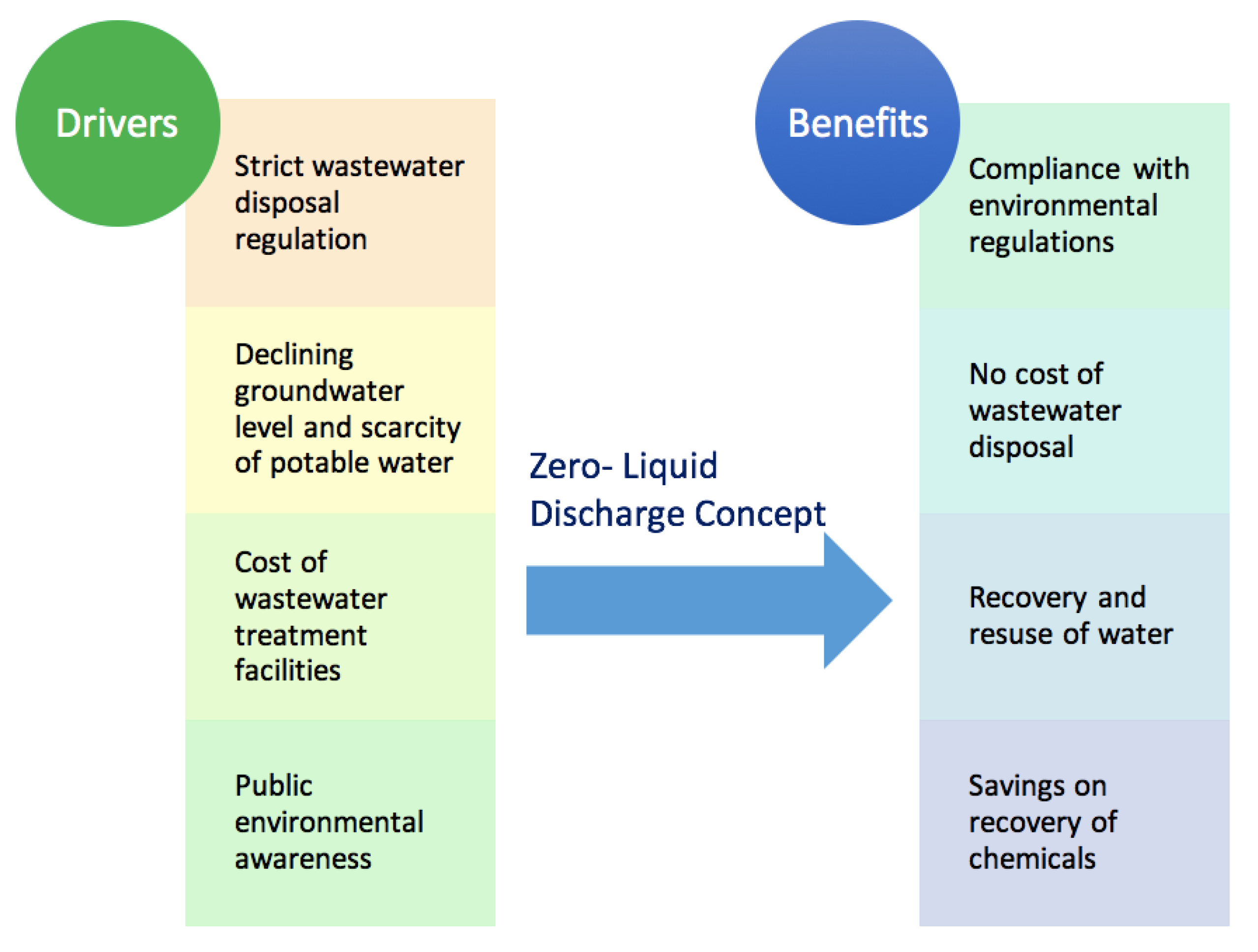
:1. Introduction
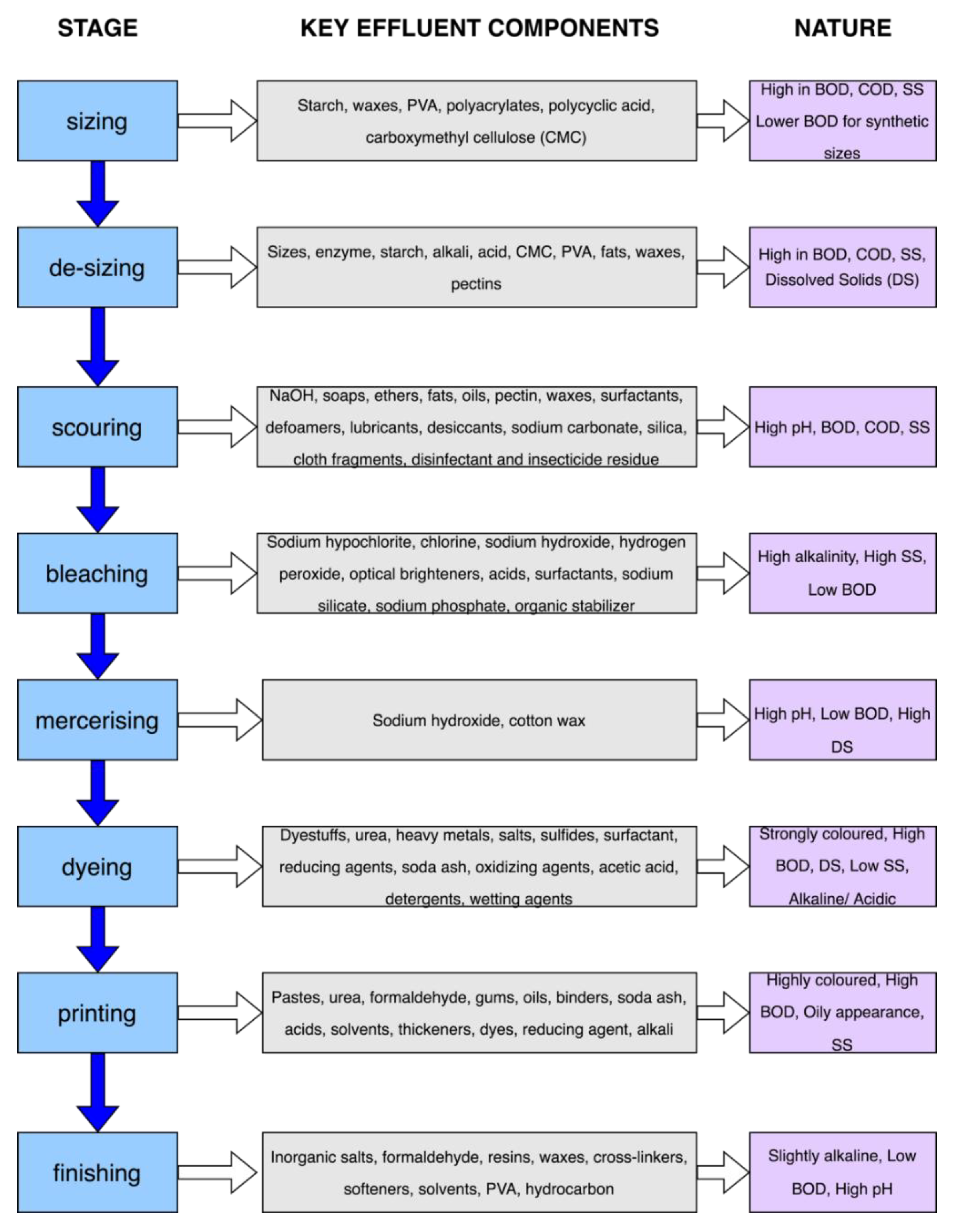
2. Stages of the Textile Processing Operation and Effluent Characteristics
3. Treatment Methods
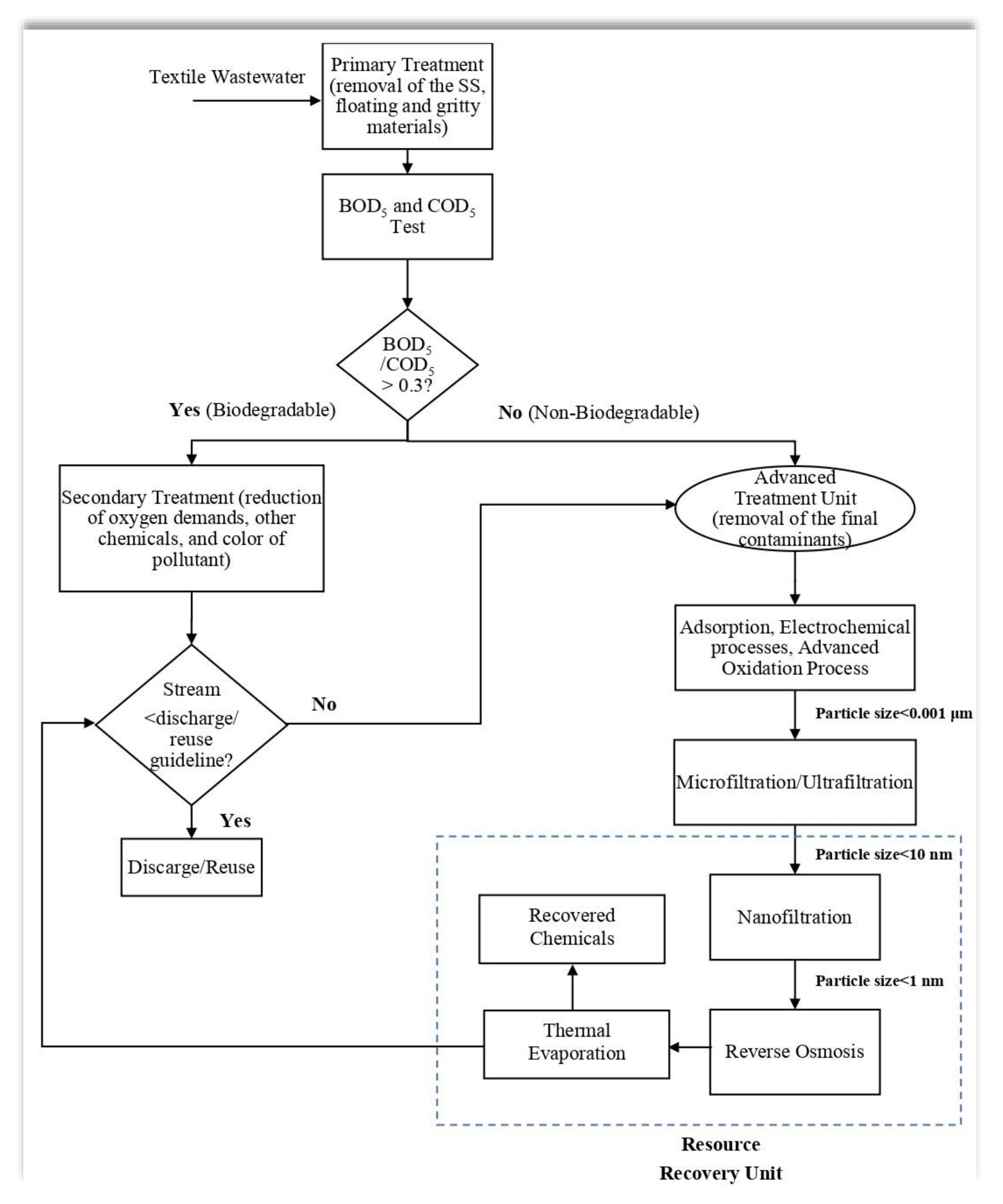
3.1. Primary Treatment
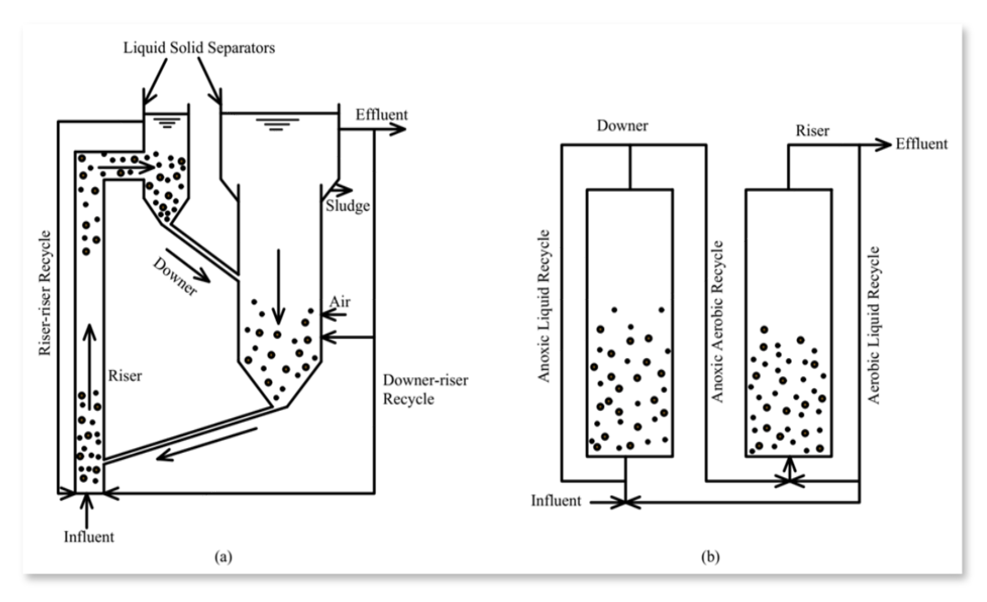
3.2. Secondary Treatment
3.3. Tertiary and Advanced Treatment
3.3.1. Electrochemical Processes
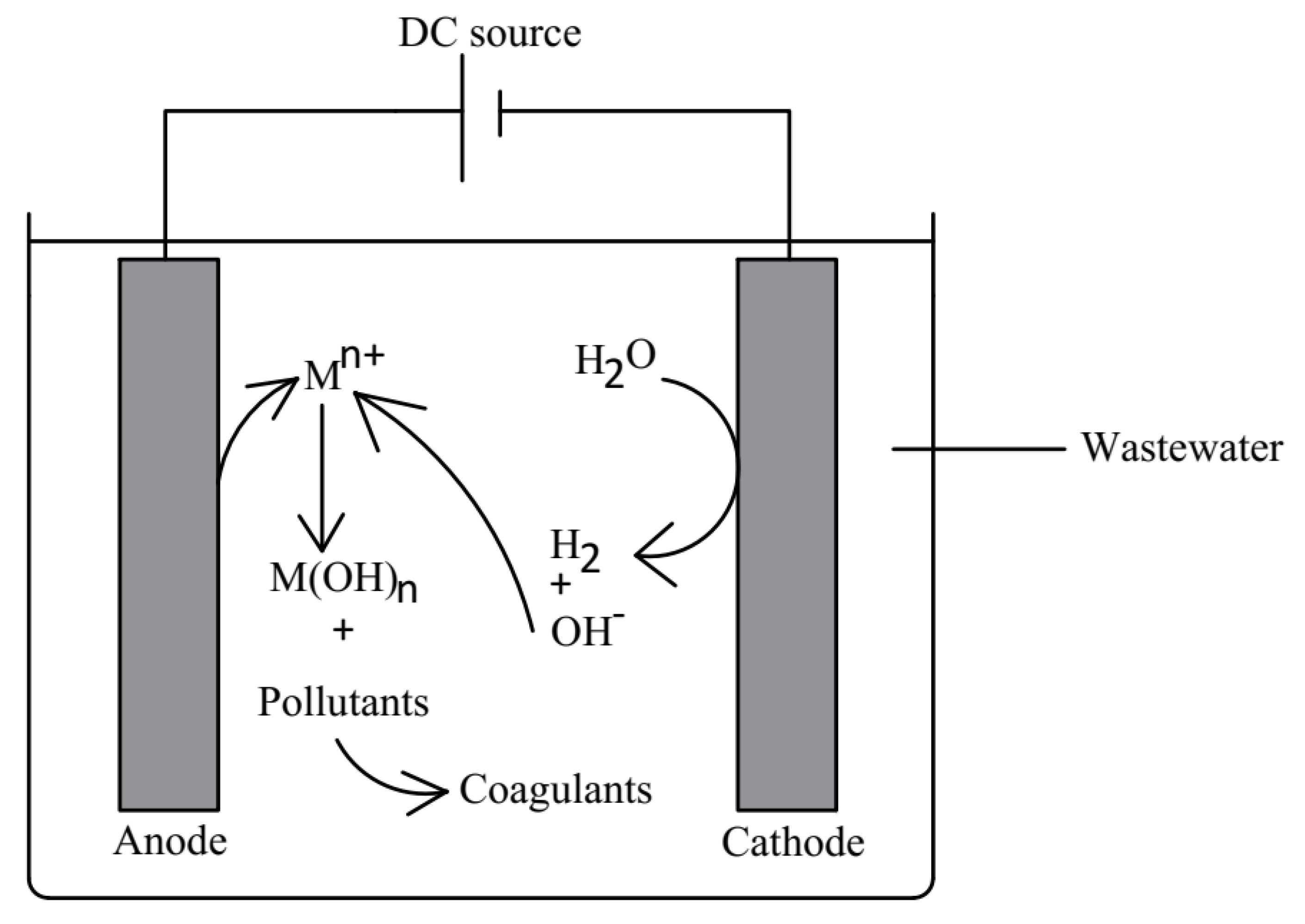
Electrocoagulation
- Anode half-cell reaction: M Mn+ + ne−
- Cathode half-cell reaction: 2H2O + 2e− 2OH− + H2
- Formation of metal hydroxide: Mn+ + nOH− M(OH)n
Photo-Assisted Electrochemical Method
- The water-splitting reaction: H2O + hυ O2 + H2
- Two half-cell reactions: 2H+ + H2O 2H+ + O2; 2H+ + 2e− H2
Electrochemical Reduction Method
Electrochemical Oxidation Method
- 2Cl− Cl2 + 2e−
- Cl2 (aq) + H2O Cl− + HClO
- Cl− + HClO H+ + ClO−
- Cl2 CO2 + H2O + Cl−
- Cl− + HClO CO2 + H2O + Cl−
- H+ + ClO− CO2 + H2O + Cl−
- H2O *OH + H+ + e−
- 2*OH H2O2
- H2O2 O2 + 2H+ + 2e−
- O2 + *O O3
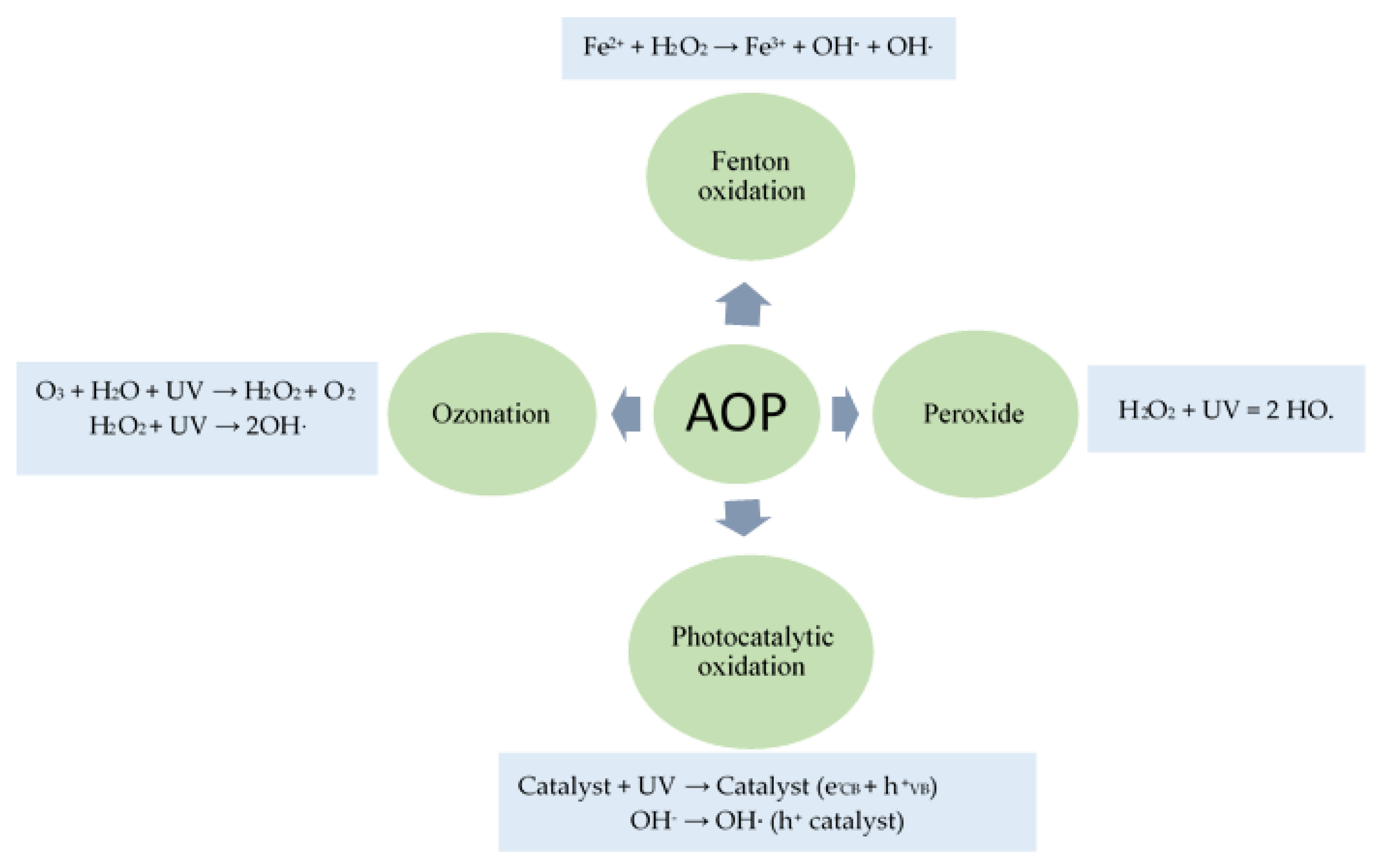
3.3.2. Advanced Oxidation Process
Fenton Oxidation
- Fe2+ + H2O2 → Fe3+ + OH− + OH.
- Fe3+ + H2O2 → Fe2+ + HOO. + H+
- OH. + H2O2 → HOO. + H2O
- HOO. + Fe3+ → Fe2+ + O2 + H+
- HOO. ↔ H+ + O2.−
- Org. + OH. → Org.. → … → CO2 + H2O
Peroxide (H2O2)
- H2O2 + UV = 2 HO.
- H2O2 + OH. → HOO. + H2O2
- H2O2 + HOO. → OH. + H2O
- OH. + OH. → H2O2
- HOO. + HOO. → H2O2 + O2
- OH. + HOO. → H2O + O2
- RX + OH. → Products
- RX + HOO. → Products
- 2NaOH + H2O2 + 6H2O → Na2O2 + 8H2O
- OH. + OH. → H2O2
- OH. + H2O2 → HOO. + H2O
- 2HOO. → H2O2 + O2.
- 2H2O2 + UV + COD → 2H2O + O2 + CODremoved
Ozonation
- The direct reaction by ozone molecules is more selective, slow reaction, favorable in acidic condition
- The indirect reaction by free radicals such as OH., HOO. etc., less selective, favorable in basic condition
- With the increase in initial dye concentration, OH. radical reaches the saturation level
- More inorganic anions are produced from a higher initial concentration of dye, so available OH. for degradation of organics is reduced
- O3 + H2O + UV → H2O2 + O2
- H2O2 + UV → 2OH.
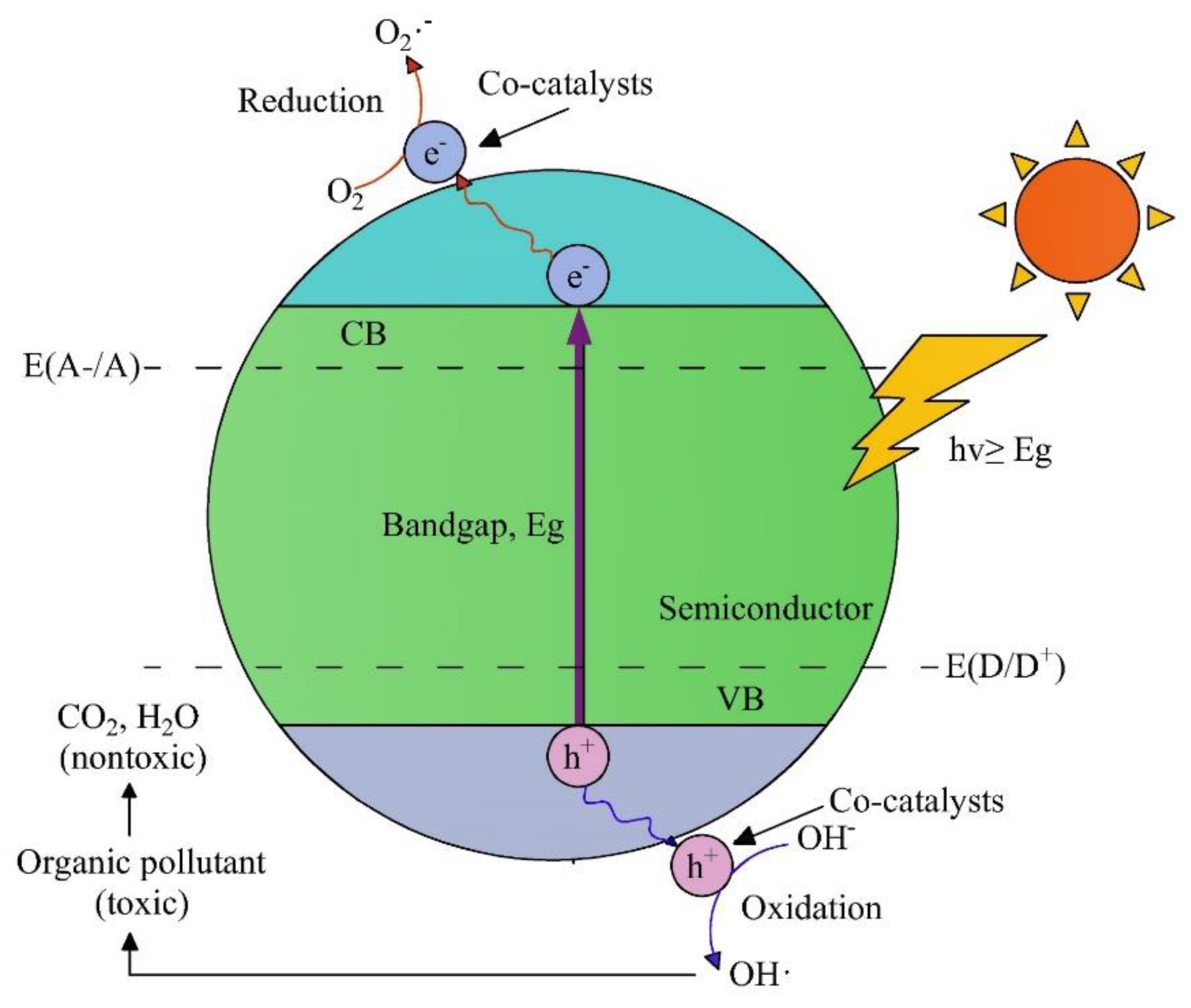
Photocatalytic Oxidation
- Catalyst + UV → Catalyst (e−CB + h+VB)
- D → D+ [co- catalyst is catalyst (h+VB)]
- A → A− [co-catalyst is a catalyst (e−CB)]
- TiO2 + UV → e−CB + h+VB
- TiO2 (OH.) + H2O + H+ → TiO2(OH.) + H+
- TiO2(OH.) + R → TiO2(OH.) + RO + H+ + e−
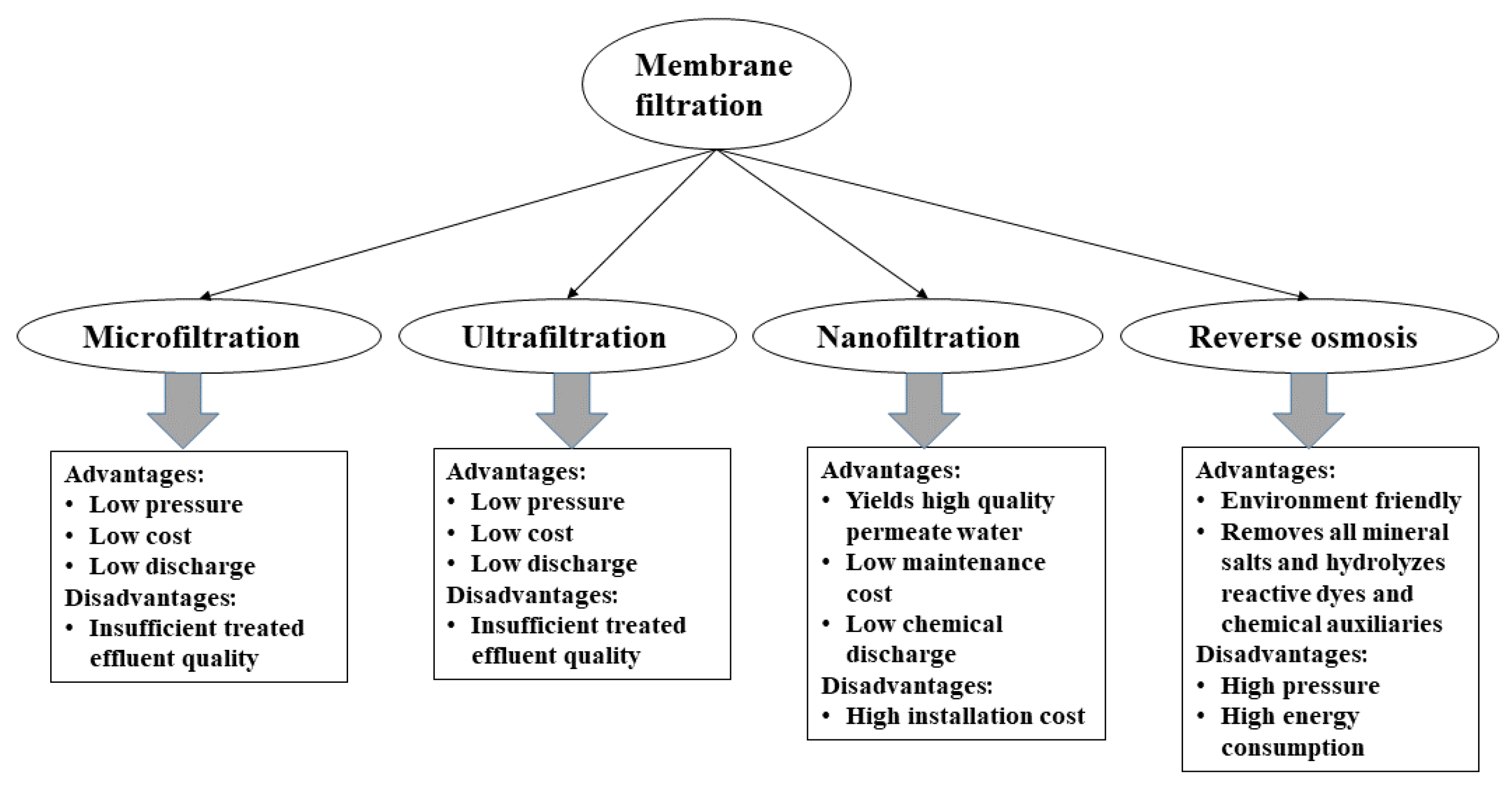
3.3.3. Membrane Filtration
Microfiltration
Ultrafiltration
Nanofiltration
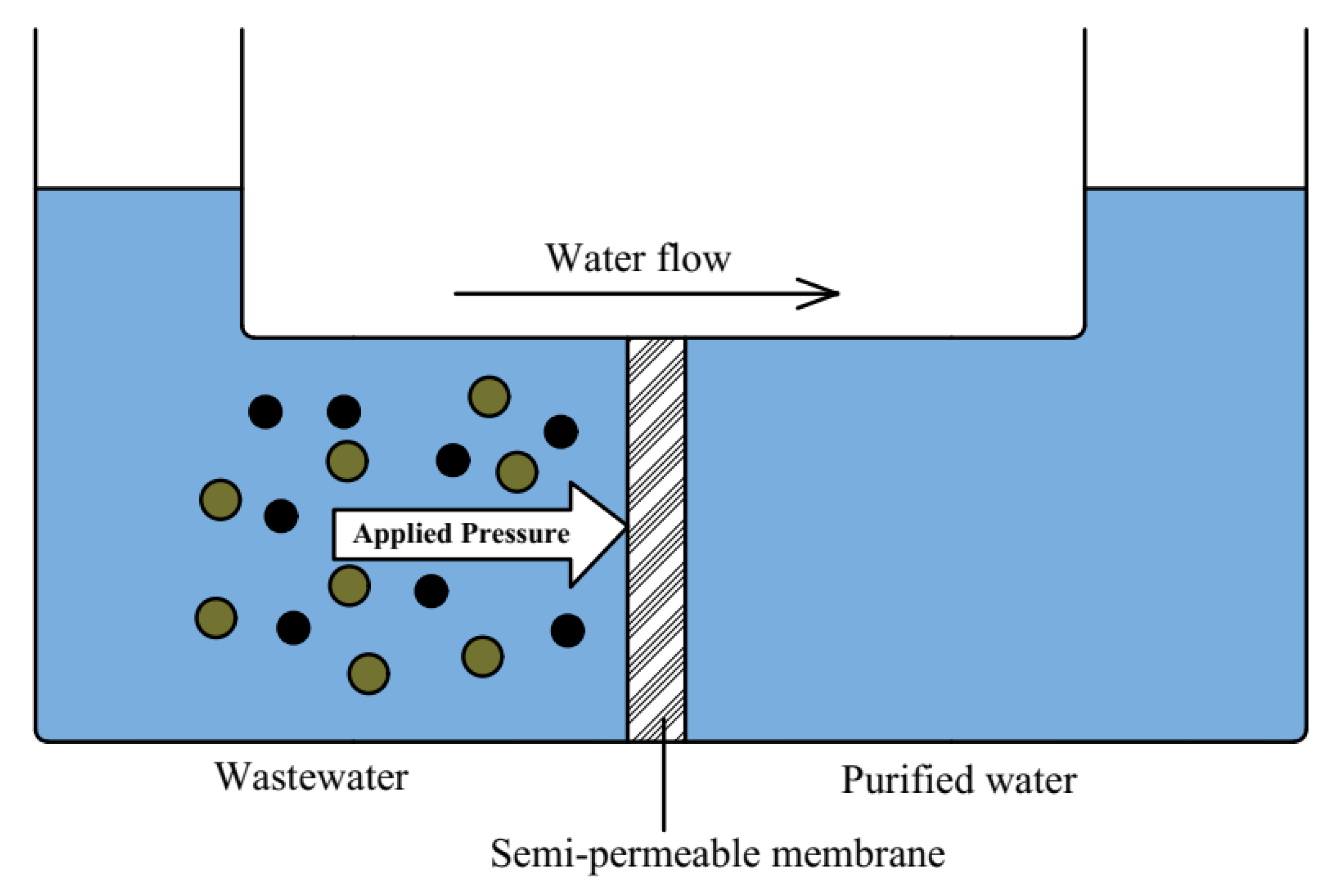
Reverse Osmosis
4. Road towards ZLD: Resource Recovery from Wastewater
4.1. Dye/Salt Recovery
4.2. Caustic Recovery
5. Conclusions
- Track water consumption at each stage of the production process (remember, you can’t improve what you don’t measure)
- Identify opportunities for water and resource recovery from each stage, considering the various ZLD techniques available
- Set a baseline for current performance and also set key performance indicators (KPI) to measure future performance
- Aim for continuous performance improvements
Author Contributions
Funding
Institutional Review Board Statement
Informed Consent Statement
Data Availability Statement
Conflicts of Interest
References
- Grant, S.B.; Saphores, J.-D.; Feldman, D.L.; Hamilton, A.J.; Fletcher, T.D.; Cook, P.L.M.; Stewardson, M.; Sanders, B.F.; Levin, L.A.; Ambrose, R.F.; et al. Taking the “Waste” Out of “Wastewater” for Human Water Security and Ecosystem Sustainability. Science 2012, 337, 681–686. [Google Scholar] [CrossRef] [PubMed] [Green Version]
- Vörösmarty, C.J.; McIntyre, P.B.; Gessner, M.O.; Dudgeon, D.; Prusevich, A.; Green, P.; Glidden, S.; Bunn, S.E.; Sullivan, C.A.; Liermann, C.R.; et al. Global threats to human water security and river biodiversity. Nature 2010, 467, 555–561. [Google Scholar] [CrossRef] [PubMed] [Green Version]
- Tong, T.; Elimelech, M. The Global Rise of Zero Liquid Discharge for Wastewater Management: Drivers, Technologies, and Future Directions. Environ. Sci. Technol. 2016, 50, 6846–6855. [Google Scholar] [CrossRef] [PubMed]
- Pervez, M.N.; Balakrishnan, M.; Hasan, S.W.; Choo, K.-H.; Zhao, Y.; Cai, Y.; Zarra, T.; Belgiorno, V.; Naddeo, V. A critical review on nanomaterials membrane bioreactor (NMs-MBR) for wastewater treatment. NPJ Clean. Water 2020, 3, 43. [Google Scholar] [CrossRef]
- Holkar, C.R.; Jadhav, A.J.; Pinjari, D.V.; Mahamuni, N.M.; Pandit, A.B. A critical review on textile wastewater treatments: Possible approaches. J. Environ. Manag. 2016, 182, 351–366. [Google Scholar] [CrossRef] [PubMed]
- Hussain, T.; Wahab, A. A critical review of the current water conservation practices in textile wet processing. J. Clean. Prod. 2018, 198, 806–819. [Google Scholar] [CrossRef]
- Schwarzenbach, R.P.; Egli, T.; Hofstetter, T.B.; von Gunten, U.; Wehrli, B. Global Water Pollution and Human Health. Annu. Rev. Environ. Resour. 2010, 35, 109–136. [Google Scholar] [CrossRef]
- Agarwal, S.; Singh, A.P. Performance evaluation of textile wastewater treatment techniques using sustainability index: An integrated fuzzy approach of assessment. J. Clean. Prod. 2022, 337, 130384. [Google Scholar] [CrossRef]
- Madhav, S.; Ahamad, A.; Singh, P.; Mishra, P.K. A review of textile industry: Wet processing, environmental impacts, and effluent treatment methods. Environ. Qual. Manag. 2018, 27, 31–41. [Google Scholar] [CrossRef]
- Lofrano, G.; Brown, J. Wastewater management through the ages: A history of mankind. Sci. Total Environ. 2010, 408, 5254–5264. [Google Scholar] [CrossRef]
- Eslamian, S.; Eslamian, F.A. Handbook of Drought and Water Scarcity: Management of Drought and Water Scarcity; CRC Press: Boca Raton, FL, USA, 2017. [Google Scholar]
- Lema, J.M.; Martinez, S.S. Innovative Wastewater Treatment & Resource Recovery Technologies: Impacts on Energy, Economy and Environment; IWA Publishing: London, UK, 2017. [Google Scholar]
- Voulvoulis, N. Water reuse from a circular economy perspective and potential risks from an unregulated approach. Curr. Opin. Environ. Sci. Health 2018, 2, 32–45. [Google Scholar] [CrossRef]
- Chequer, F.D.; De Oliveira, G.R.; Ferraz, E.A.; Cardoso, J.C.; Zanoni, M.B.; De Oliveira, D.P. Chapter 6—Textile Dyes: Dyeing Process and Environmental Impact. In Eco-Friendly Textile Dyeing and Finishing; Melih, G., Ed.; IntechOpen: Rijeka, Croatia, 2013. [Google Scholar]
- Gao, B.; Huang, X.; Jiang, T.; Pervez, M.N.; Zhu, W.; Hassan, M.M.; Cai, Y.; Naddeo, V. Sustainable dyeing of ramie fiber with ternary reactive dye mixtures in liquid ammonia. RSC Adv. 2022, 12, 19253–19264. [Google Scholar] [CrossRef] [PubMed]
- Yaseen, D.A.; Scholz, M. Treatment of synthetic textile wastewater containing dye mixtures with microcosms. Environ. Sci. Pollut. Res. 2018, 25, 1980–1997. [Google Scholar] [CrossRef] [PubMed] [Green Version]
- Lin, J.; Ye, W.; Huang, J.; Ricard, B.; Baltaru, M.-C.; Greydanus, B.; Balta, S.; Shen, J.; Vlad, M.; Sotto, A.; et al. Toward Resource Recovery from Textile Wastewater: Dye Extraction, Water and Base/Acid Regeneration Using a Hybrid NF-BMED Process. ACS Sustain. Chem. Eng. 2015, 3, 1993–2001. [Google Scholar] [CrossRef]
- Kesari, K.K.; Soni, R.; Jamal, Q.M.S.; Tripathi, P.; Lal, J.A.; Jha, N.K.; Siddiqui, M.H.; Kumar, P.; Tripathi, V.; Ruokolainen, J. Wastewater Treatment and Reuse: A Review of its Applications and Health Implications. Water Air Soil Pollut. 2021, 232, 208. [Google Scholar] [CrossRef]
- Wang, X.; Jiang, J.; Gao, W. Reviewing textile wastewater produced by industries: Characteristics, environmental impacts, and treatment strategies. Water Sci. Technol. 2022, 85, 2076–2096. [Google Scholar] [CrossRef]
- Ibrahim, Y.; Banat, F.; Naddeo, V.; Hasan, S.W. Numerical modeling of an integrated OMBR-NF hybrid system for simultaneous wastewater reclamation and brine management. Euro-Mediterr. J. Environ. Integr. 2019, 4, 23. [Google Scholar] [CrossRef]
- Muhammad, Y.; Lee, W. Zero-liquid discharge (ZLD) technology for resource recovery from wastewater: A review. Sci. Total Environ. 2019, 681, 551–563. [Google Scholar] [CrossRef]
- Lin, J.; Lin, F.; Chen, X.; Ye, W.; Li, X.; Zeng, H.; Van der Bruggen, B. Sustainable Management of Textile Wastewater: A Hybrid Tight Ultrafiltration/Bipolar-Membrane Electrodialysis Process for Resource Recovery and Zero Liquid Discharge. Ind. Eng. Chem. Res. 2019, 58, 11003–11012. [Google Scholar] [CrossRef]
- Date, M.; Patyal, V.; Jaspal, D.; Malviya, A.; Khare, K. Zero liquid discharge technology for recovery, reuse, and reclamation of wastewater: A critical review. J. Water Process Eng. 2022, 49, 103129. [Google Scholar] [CrossRef]
- Altınay, A.D.; Yazagan, A.; Koseoglu-Imer, D.Y.; Keskinler, B.; Koyuncu, I. Membrane Concentrate Management Model of Biologically Pre-treated Textile Wastewater for Zero-Liquid Discharge. Water Air Soil Pollut. 2022, 233, 303. [Google Scholar] [CrossRef]
- Ricky, R.; Shanthakumar, S.; Ganapathy, G.P.; Chiampo, F. Zero Liquid Discharge System for the Tannery Industry–An Overview of Sustainable Approaches. Recycling 2022, 7, 31. [Google Scholar] [CrossRef]
- Siddique, K.; Rizwan, M.; Shahid, M.J.; Ali, S.; Ahmad, R.; Rizvi, H. Textile Wastewater Treatment Options: A Critical Review. In Enhancing Cleanup of Environmental Pollutants: Volume 2: Non-Biological Approaches; Anjum, N.A., Gill, S.S., Tuteja, N., Eds.; Springer International Publishing: Cham, Switzerland, 2017; pp. 183–207. [Google Scholar]
- Bisschops, I.; Spanjers, H. Literature review on textile wastewater characterisation. Environ. Technol. 2003, 24, 1399–1411. [Google Scholar] [CrossRef] [PubMed]
- Yaseen, D.A.; Scholz, M. Textile dye wastewater characteristics and constituents of synthetic effluents: A critical review. Int. J. Environ. Sci. Technol. 2019, 16, 1193–1226. [Google Scholar] [CrossRef] [Green Version]
- Ul-Haq, N.; Nasir, H. Cleaner production technologies in desizing of cotton fabric. J. Text. Inst. 2012, 103, 304–310. [Google Scholar] [CrossRef]
- Tanapongpipat, A.; Khamman, C.; Pruksathorm, K.; Hunsom, M. Process modification in the scouring process of textile industry. J. Clean. Prod. 2008, 16, 152–158. [Google Scholar] [CrossRef]
- Li, Q.; Zhao, X.; Quan, H.; Zhou, Y. Establishing an energy-saving scouring/bleaching one-step process for cotton/spandex fabric using UVA-assisted irradiation. RSC Adv. 2022, 12, 9404–9415. [Google Scholar] [CrossRef]
- Inamdar, U.Y.; Pervez, N.; Navik, R.G.; Peng, X.; Cai, Y. Low-temperature bleaching of cotton fabric by activated peroxide system. Emerg. Mater. Res. 2017, 6, 387–395. [Google Scholar] [CrossRef]
- Abdel-Halim, E.S.; Al-Deyab, S.S. Low temperature bleaching of cotton cellulose using peracetic acid. Carbohydr. Polym. 2011, 86, 988–994. [Google Scholar] [CrossRef]
- Wahab, A.; Hussain, T.; Ashraf, M. Water conservation in garment bleaching using aerosol technology. Text. Res. J. 2022, 92, 4629–4638. [Google Scholar] [CrossRef]
- Zhang, Y.; Shao, S.; Yu, W.; Yang, F.; Xu, X. Study on recycling alkali from the wastewater of textile mercerization process by nanofiltration. Ieri Procedia 2014, 9, 71–76. [Google Scholar] [CrossRef] [Green Version]
- Uddin, F. Environmental hazard in textile dyeing wastewater from local textile industry. Cellulose 2021, 28, 10715–10739. [Google Scholar] [CrossRef]
- Samsami, S.; Mohamadizaniani, M.; Sarrafzadeh, M.-H.; Rene, E.R.; Firoozbahr, M. Recent advances in the treatment of dye-containing wastewater from textile industries: Overview and perspectives. Process Saf. Environ. Prot. 2020, 143, 138–163. [Google Scholar] [CrossRef]
- Correia, V.M.; Stephenson, T.; Judd, S.J. Characterisation of textile wastewaters—A review. Environ. Technol. 1994, 15, 917–929. [Google Scholar] [CrossRef]
- Natarajan, P.; Karmegam, P.M.; Madasamy, J.; Somasundaram, S.; Ganesan, S. Effective treatment of domestic sewage to reuse in textile dyeing and catalytic treatment of generated dye wastewater. Int. J. Environ. Sci. Technol. 2022. [Google Scholar] [CrossRef]
- Vasconcelos, M.W.; Gonçalves, S.; de Oliveira, E.C.; Rubert, S.; de Castilhos Ghisi, N. Textile effluent toxicity trend: A scientometric review. J. Clean. Prod. 2022, 366, 132756. [Google Scholar] [CrossRef]
- Periyasamy, A.P.; Ramamoorthy, S.K.; Rwawiire, S.; Zhao, Y. Sustainable Wastewater Treatment Methods for Textile Industry. In Sustainable Innovations in Apparel Production; Muthu, S.S., Ed.; Springer Singapore: Singapore, 2018; pp. 21–87. [Google Scholar]
- Ahmed, M.A. Reduction of Textile Industrial Waste water Pollution. Gezira J. Eng. Appl. Sci. 2018, 10, 1–12. [Google Scholar]
- Savin, I.-I.; Butnaru, R. Wastewater characteristics in textile finishing mills. Environ. Eng. Manag. J. (EEMJ) 2008, 7, 859–864. [Google Scholar] [CrossRef]
- Zaharia, C.; Suteu, D. Chapter 3—Textile Organic Dyes—Characteristics, Polluting Effects and Separation/Elimination Procedures from Industrial Effluents—A Critical Overview. In Organic Pollutants Ten Years after the Stockholm Convention; Tomasz, P., Aleksandra, M.-S., Eds.; IntechOpen: Rijeka, Croatia, 2012. [Google Scholar]
- Ministry of Environment and Forest, Bangladesh. Guide for Assessment of Effluent Treatment Plants; Ministry of Environment and Forest, Bangladesh: Dhaka, Bangladesh, 2008; p. 79.
- Yukseler, H.; Uzal, N.; Sahinkaya, E.; Kitis, M.; Dilek, F.B.; Yetis, U. Analysis of the best available techniques for wastewaters from a denim manufacturing textile mill. J. Environ. Manag. 2017, 203, 1118–1125. [Google Scholar] [CrossRef]
- Katheresan, V.; Kansedo, J.; Lau, S.Y. Efficiency of various recent wastewater dye removal methods: A review. J. Environ. Chem. Eng. 2018, 6, 4676–4697. [Google Scholar] [CrossRef]
- Rai, H.S.; Bhattacharyya, M.S.; Singh, J.; Bansal, T.; Vats, P.; Banerjee, U. Removal of dyes from the effluent of textile and dyestuff manufacturing industry: A review of emerging techniques with reference to biological treatment. Crit. Rev. Environ. Sci. Technol. 2005, 35, 219–238. [Google Scholar] [CrossRef]
- Senthil Kumar, P.; Saravanan, A. Sustainable wastewater treatments in textile sector. In Sustainable Fibres and Textiles; Muthu, S.S., Ed.; Woodhead Publishing: Sawston, UK, 2017; pp. 323–346. [Google Scholar]
- Mostafa, M. Waste water treatment in textile Industries-the concept and current removal technologies. J. Biodivers. Environ. Sci. 2015, 7, 501–525. [Google Scholar]
- Ghaly, A.; Ananthashankar, R.; Alhattab, M.; Ramakrishnan, V. Production, characterization and treatment of textile effluents: A critical review. J. Chem. Eng. Process Technol. 2014, 5, 1–19. [Google Scholar]
- Asia, I.; Oladoja, N.; Bamuza-Pemu, E. Treatment of textile sludge using anaerobic technology. Afr. J. Biotechnol. 2006, 5, 1678–1683. [Google Scholar]
- Goel, R.K.; Flora, J.R.V.; Chen, J.P. Flow Equalization and Neutralization. In Physicochemical Treatment Processes; Wang, L.K., Hung, Y.-T., Shammas, N.K., Eds.; Humana Press: Totowa, NJ, USA, 2005; pp. 21–45. [Google Scholar]
- Liu, D.H.; Lipták, B.G. Wastewater Treatment; CRC Press: Boca Raton, FL, USA, 2020. [Google Scholar]
- Babu, B.R.; Parande, A.; Raghu, S.; Kumar, T.P. Cotton textile processing: Waste generation and effluent treatment. J. Cotton Sci. 2007, 11, 141–153. [Google Scholar]
- Hassan, M.A.; Li, T.P.; Noor, Z.Z. Coagulation and flocculation treatment of wastewater in textile industry using chitosan. J. Chem. Nat. Resour. Eng. 2009, 4, 43–53. [Google Scholar]
- Arulmathi, P.; Jeyaprabha, C.; Sivasankar, P.; Rajkumar, V. Treatment of Textile Wastewater by Coagulation–Flocculation Process Using Gossypium herbaceum and Polyaniline Coagulants. CLEAN–Soil Air Water 2019, 47, 1800464. [Google Scholar] [CrossRef]
- Tripathy, T.; De, B.R. Flocculation: A new way to treat the waste water. J. Phys. Sci. 2006, 10, 93–127. [Google Scholar]
- Asif, M.B.; Majeed, N.; Iftekhar, S.; Habib, R.; Fida, S.; Tabraiz, S. Chemically enhanced primary treatment of textile effluent using alum sludge and chitosan. Desalin. Water Treat. 2016, 57, 7280–7286. [Google Scholar] [CrossRef]
- Samer, M. Biological and chemical wastewater treatment processes. Wastewater Treat. Eng. 2015, 150, 212. [Google Scholar]
- Ulson de Souza, A.A.; Brandão, H.L.; Zamporlini, I.M.; Soares, H.M.; Guelli Ulson de Souza, S.M.d.A. Application of a fluidized bed bioreactor for cod reduction in textile industry effluents. Resour. Conserv. Recycl. 2008, 52, 511–521. [Google Scholar] [CrossRef]
- Kuppusamy, S.; Sethurajan, M.; Kadarkarai, M.; Aruliah, R. Biodecolourization of textile dyes by novel, indigenous Pseudomonas stutzeri MN1 and Acinetobacter baumannii MN3. J. Environ. Chem. Eng. 2017, 5, 716–724. [Google Scholar] [CrossRef]
- Haq, I.; Raj, A.; Markandeya. Biodegradation of Azure-B dye by Serratia liquefaciens and its validation by phytotoxicity, genotoxicity and cytotoxicity studies. Chemosphere 2018, 196, 58–68. [Google Scholar] [CrossRef] [PubMed]
- Padmanaban, V.C.; Geed, S.R.; Achary, A.; Singh, R.S. Kinetic studies on degradation of Reactive Red 120 dye in immobilized packed bed reactor by Bacillus cohnii RAPT1. Bioresour. Technol. 2016, 213, 39–43. [Google Scholar] [CrossRef]
- Khan, S.S.; Arunarani, A.; Chandran, P. Biodegradation of Basic Violet 3 and Acid Blue 93 by Pseudomonas putida. CLEAN–Soil Air Water 2015, 43, 67–72. [Google Scholar] [CrossRef]
- Aruna, B.; Silviya, L.R.; Kumar, E.S.; Rani, P.R.; Prasad, D.V.; VijayaLakshmi, D. Decolorization of Acid Blue 25 dye by individual and mixed bacterial consortium isolated from textile effluents. Int. J. Curr. Microbiol. Appl. Sci. 2015, 4, 1015–1024. [Google Scholar]
- Sinha, A.; Lulu, S.; Vino, S.; Banerjee, S.; Acharjee, S.; Osborne, W.J. Degradation of reactive green dye and textile effluent by Candida sp. VITJASS isolated from wetland paddy rhizosphere soil. J. Environ. Chem. Eng. 2018, 6, 5150–5159. [Google Scholar] [CrossRef]
- Bankole, P.O.; Adekunle, A.A.; Govindwar, S.P. Enhanced decolorization and biodegradation of acid red 88 dye by newly isolated fungus, Achaetomium strumarium. J. Environ. Chem. Eng. 2018, 6, 1589–1600. [Google Scholar] [CrossRef]
- Ashrafi, S.D.; Rezaei, S.; Forootanfar, H.; Mahvi, A.H.; Faramarzi, M.A. The enzymatic decolorization and detoxification of synthetic dyes by the laccase from a soil-isolated ascomycete, Paraconiothyrium variabile. Int. Biodeterior. Biodegrad. 2013, 85, 173–181. [Google Scholar] [CrossRef]
- Bankole, P.O.; Adekunle, A.A.; Obidi, O.F.; Chandanshive, V.V.; Govindwar, S.P. Biodegradation and detoxification of Scarlet RR dye by a newly isolated filamentous fungus, Peyronellaea prosopidis. Sustain. Environ. Res. 2018, 28, 214–222. [Google Scholar] [CrossRef]
- Gao, T.; Qin, D.; Zuo, S.; Peng, Y.; Xu, J.; Yu, B.; Song, H.; Dong, J. Decolorization and detoxification of triphenylmethane dyes by isolated endophytic fungus, Bjerkandera adusta SWUSI4 under non-nutritive conditions. Bioresour. Bioprocess. 2020, 7, 53. [Google Scholar] [CrossRef]
- Ishchi, T.; Sibi, G. Azo dye degradation by Chlorella vulgaris: Optimization and kinetics. Int. J. Biol. Chem. 2020, 14, 1–7. [Google Scholar] [CrossRef] [Green Version]
- El-Sheekh, M.M.; Gharieb, M.M.; Abou-El-Souod, G.W. Biodegradation of dyes by some green algae and cyanobacteria. Int. Biodeterior. Biodegrad. 2009, 63, 699–704. [Google Scholar] [CrossRef]
- Khataee, A.; Dehghan, G.; Zarei, M.; Fallah, S.; Niaei, G.; Atazadeh, I. Degradation of an azo dye using the green macroalga Enteromorpha sp. Chem. Ecol. 2013, 29, 221–233. [Google Scholar] [CrossRef]
- Wang, Z.; Xue, M.; Huang, K.; Liu, Z. Textile dyeing wastewater treatment. Adv. Treat. Text. Effl. 2011, 5, 91–116. [Google Scholar]
- Mullai, P.; Yogeswari, M.K.; Vishali, S.; Tejas Namboodiri, M.M.; Gebrewold, B.D.; Rene, E.R.; Pakshirajan, K. Aerobic Treatment of Effluents From Textile Industry. In Current Developments in Biotechnology and Bioengineering; Lee, D.-J., Jegatheesan, V., Ngo, H.H., Hallenbeck, P.C., Pandey, A., Eds.; Elsevier: Amsterdam, The Netherlands, 2017; pp. 3–34. [Google Scholar]
- Alsubih, M.; El Morabet, R.; Khan, R.A.; Khan, N.A.; Khan, A.R.; Sharma, G. Performance evaluation of aerobic fluidized bed bioreactor coupled with tube-settler for hospital wastewater treatment. J. Environ. Chem. Eng. 2021, 9, 105896. [Google Scholar] [CrossRef]
- Ochieng, A.; Odiyo, J.O.; Mutsago, M. Biological treatment of mixed industrial wastewaters in a fluidised bed reactor. J. Hazard. Mater. 2003, 96, 79–90. [Google Scholar] [CrossRef]
- Kunii, D.; Levenspiel, O. Fluidization Engineering; Butterworth-Heinemann: Oxford, UK, 1991. [Google Scholar]
- Andalib, M.; Nakhla, G.; Zhu, J. Biological Nutrient Removal Using a Novel Laboratory-Scale Twin Fluidized-Bed Bioreactor. Chem. Eng. Technol. 2010, 33, 1125–1136. [Google Scholar] [CrossRef]
- Nelson, M.J.; Nakhla, G.; Zhu, J. Fluidized-Bed Bioreactor Applications for Biological Wastewater Treatment: A Review of Research and Developments. Engineering 2017, 3, 330–342. [Google Scholar] [CrossRef]
- Mizyed, A. Review on Application of Rotating Biological Contactor in Removal of Various Pollutants From Effluent. Tech. BioChemMed 2021, 2, 41–61. [Google Scholar]
- Ghodeif, K. Baseline Assessment Study for Wastewater Treatment Plant for Al Gozayyera Village, West Kantara City, Ismailia Governorate, Egypt. In Network of Demonstration Activities for Sustainable Integrated Wastewater Treatment and Reuse in the Mediterranean; SWIM Sustain Water MED: Cairo, Egypt, 2013. [Google Scholar]
- Albahnasawi, A.; Agir, H.; Cicerali, M.F.; Özdoğan, N.; Gurbulak, E.; Yildirim, M.; Eyvaz, M.; Yuksel, E. Performance of aerobic sequential batch reactor in the treatment of textile wastewaters. Int. J. Environ. Sci. Technol. 2022. [Google Scholar] [CrossRef]
- Khan, N.A.; Khan, S.U.; Islam, D.T.; Ahmed, S.; Farooqi, I.H.; Isa, M.H.; Hussain, A.; Changani, F.; Dhingra, A. Performance evaluation of column-SBR in paper and pulp wastewater treatment: Optimization and bio-kinetics. Desalin. Water Treat. 2019, 156, 204–219. [Google Scholar] [CrossRef] [Green Version]
- Ogleni, N.; Damar Arifoglu, Y.; Ileri, R. Microbiological and Performance Evaluation of Sequencing Batch Reactor for Textile Wastewater Treatment. Water Environ. Res. 2012, 84, 346–353. [Google Scholar] [PubMed]
- Aziz, S.Q.; Aziz, H.A.; Mojiri, A.; Bashir, M.J.; Amr, S.S.A. Landfill leachate treatment using sequencing batch reactor (SBR) process: Limitation of operational parameters and performance. Int. J. Sci. Res. Knowl. 2013, 1, 34–43. [Google Scholar] [CrossRef]
- Song, W.; Xie, B.; Huang, S.; Zhao, F.; Shi, X. Aerobic membrane bioreactors for industrial wastewater treatment. In Current Developments in Biotechnology and Bioengineering; Ng, H.Y., Ng, T.C.A., Ngo, H.H., Mannina, G., Pandey, A., Eds.; Elsevier: Amsterdam, The Netherlands, 2020; pp. 129–145. [Google Scholar]
- Spagni, A.; Casu, S.; Grilli, S. Decolourisation of textile wastewater in a submerged anaerobic membrane bioreactor. Bioresour. Technol. 2012, 117, 180–185. [Google Scholar] [CrossRef]
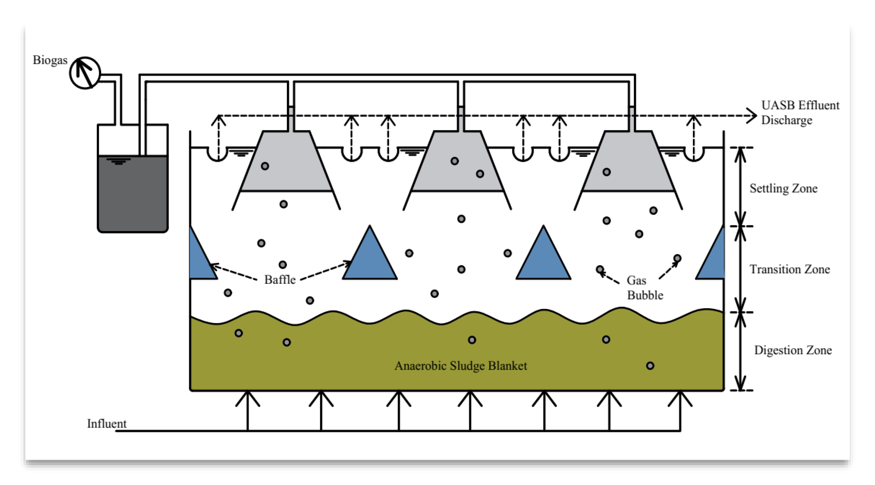
- Rajagopal, R.; Choudhury, M.R.; Anwar, N.; Goyette, B.; Rahaman, M.S. Influence of Pre-Hydrolysis on Sewage Treatment in an Up-Flow Anaerobic Sludge BLANKET (UASB) Reactor: A Review. Water 2019, 11, 372. [Google Scholar] [CrossRef] [Green Version]
- Pererva, Y.; Miller, C.D.; Sims, R.C. Approaches in Design of Laboratory-Scale UASB Reactors. Processes 2020, 8, 734. [Google Scholar] [CrossRef]
- de Almeida, R.; de Souza Guimarães, C. Up-Flow Anaerobic Sludge Blanket Reactors in Dye Removal: Mechanisms, Influence Factors, and Performance. In Biological Approaches in Dye-Containing Wastewater; Khadir, A., Muthu, S.S., Eds.; Springer Singapore: Singapore, 2022; Volume 1, pp. 201–227. [Google Scholar]
- Ozdemir, S.; Cirik, K.; Akman, D.; Sahinkaya, E.; Cinar, O. Treatment of azo dye-containing synthetic textile dye effluent using sulfidogenic anaerobic baffled reactor. Bioresour. Technol. 2013, 146, 135–143. [Google Scholar] [CrossRef]
- Ali, H. Biodegradation of Synthetic Dyes—A Review. Water Air Soil Pollut. 2010, 213, 251–273. [Google Scholar] [CrossRef]
- Afroze, S.; Sen, T.K. A Review on Heavy Metal Ions and Dye Adsorption from Water by Agricultural Solid Waste Adsorbents. Water Air Soil Pollut. 2018, 229, 225. [Google Scholar] [CrossRef]
- Hossain, M.Y.; Zhu, W.; Pervez, M.N.; Yang, X.; Sarker, S.; Hassan, M.M.; Hoque, M.I.U.; Naddeo, V.; Cai, Y. Adsorption, kinetics, and thermodynamic studies of cacao husk extracts in waterless sustainable dyeing of cotton fabric. Cellulose 2021, 28, 2521–2536. [Google Scholar] [CrossRef]
- Othman, N.H.; Alias, N.H.; Shahruddin, M.Z.; Abu Bakar, N.F.; Nik Him, N.R.; Lau, W.J. Adsorption kinetics of methylene blue dyes onto magnetic graphene oxide. J. Environ. Chem. Eng. 2018, 6, 2803–2811. [Google Scholar] [CrossRef]
- Sakil, M.; Nahid, P.M.; Faridul, H.K.M.; Abu, T.M.; Hui-Hong, L. In situ synthesis of green AgNPs on ramie fabric with functional and catalytic properties. Emerg. Mater. Res. 2019, 8, 623–633. [Google Scholar]
- Xia, M.; Chen, Z.; Li, Y.; Li, C.; Ahmad, N.M.; Cheema, W.A.; Zhu, S. Removal of Hg(ii) in aqueous solutions through physical and chemical adsorption principles. RSC Adv. 2019, 9, 20941–20953. [Google Scholar] [CrossRef] [PubMed] [Green Version]
- Gupta, N.; Kushwaha, A.K.; Chattopadhyaya, M.C. Application of potato (Solanum tuberosum) plant wastes for the removal of methylene blue and malachite green dye from aqueous solution. Arab. J. Chem. 2016, 9, S707–S716. [Google Scholar] [CrossRef] [Green Version]
- Balarak, D.; Zafariyan, M.; Igwegbe, C.A.; Onyechi, K.K.; Ighalo, J.O. Adsorption of Acid Blue 92 Dye from Aqueous Solutions by Single-Walled Carbon Nanotubes: Isothermal, Kinetic, and Thermodynamic Studies. Environ. Process. 2021, 8, 869–888. [Google Scholar] [CrossRef]
- Gapusan, R.B.; Balela, M.D.L. Adsorption of anionic methyl orange dye and lead(II) heavy metal ion by polyaniline-kapok fiber nanocomposite. Mater. Chem. Phys. 2020, 243, 122682. [Google Scholar] [CrossRef]
- Elsherif, K.; El-Dali, A.; Alkarewi, A.; Ewlad-Ahmed, A.; Treban, A. Adsorption of crystal violet dye onto olive leaves powder: Equilibrium and kinetic studies. Chem. Int. 2021, 7, 79–89. [Google Scholar]
- Jahan, N.; Roy, H.; Reaz, A.H.; Arshi, S.; Rahman, E.; Firoz, S.H.; Islam, M.S. A comparative study on sorption behavior of graphene oxide and reduced graphene oxide towards methylene blue. Case Stud. Chem. Environ. Eng. 2022, 6, 100239. [Google Scholar] [CrossRef]
- Cherdchoo, W.; Nithettham, S.; Charoenpanich, J. Removal of Cr(VI) from synthetic wastewater by adsorption onto coffee ground and mixed waste tea. Chemosphere 2019, 221, 758–767. [Google Scholar] [CrossRef]
- Pavithra, S.; Thandapani, G.; Sugashini, S.; Sudha, P.N.; Alkhamis, H.H.; Alrefaei, A.F.; Almutairi, M.H. Batch adsorption studies on surface tailored chitosan/orange peel hydrogel composite for the removal of Cr(VI) and Cu(II) ions from synthetic wastewater. Chemosphere 2021, 271, 129415. [Google Scholar] [CrossRef] [PubMed]
- Qu, J.; Meng, X.; Jiang, X.; You, H.; Wang, P.; Ye, X. Enhanced removal of Cd(II) from water using sulfur-functionalized rice husk: Characterization, adsorptive performance and mechanism exploration. J. Clean. Prod. 2018, 183, 880–886. [Google Scholar] [CrossRef]
- Sala, M.; Gutiérrez-Bouzán, M.C. Electrochemical Techniques in Textile Processes and Wastewater Treatment. Int. J. Photoenergy 2012, 2012, 629103. [Google Scholar] [CrossRef]
- Bazrafshan, E.; Mahvi, A.H.; Zazouli, M.a. Textile Wastewater Treatment by Electrocoagulation Process using Aluminum Electrodes. Iran. J. Health Sci. 2014, 2, 16–29. [Google Scholar] [CrossRef] [Green Version]
- Mahmoodi, N.M.; Dalvand, A. Treatment of colored textile wastewater containing acid dye using electrocoagulation process. Desalin. Water Treat. 2013, 51, 5959–5964. [Google Scholar] [CrossRef]
- Kamaraj, R.; Ganesan, P.; Vasudevan, S. Removal of lead from aqueous solutions by electrocoagulation: Isotherm, kinetics and thermodynamic studies. Int. J. Environ. Sci. Technol. 2015, 12, 683–692. [Google Scholar] [CrossRef] [Green Version]
- Vasudevan, S.; Lakshmi, J.; Sozhan, G. Electrocoagulation Studies on the Removal of Copper from Water Using Mild Steel Electrode. Water Environ. Res. 2012, 84, 209–219. [Google Scholar] [CrossRef]
- Solano, A.M.S.; Garcia-Segura, S.; Martínez-Huitle, C.A.; Brillas, E. Degradation of acidic aqueous solutions of the diazo dye Congo Red by photo-assisted electrochemical processes based on Fenton’s reaction chemistry. Appl. Catal. B: Environ. 2015, 168–169, 559–571. [Google Scholar] [CrossRef]
- Umukoro, E.H.; Peleyeju, M.G.; Ngila, J.C.; Arotiba, O.A. Towards wastewater treatment: Photo-assisted electrochemical degradation of 2-nitrophenol and orange II dye at a tungsten trioxide-exfoliated graphite composite electrode. Chem. Eng. J. 2017, 317, 290–301. [Google Scholar] [CrossRef]
- Sánchez-Sánchez, A.; Tejocote-Pérez, M.; Fuentes-Rivas, R.M.; Linares-Hernández, I.; Martínez-Miranda, V.; Fonseca-Montes de Oca, R.M.G. Treatment of a Textile Effluent by Electrochemical Oxidation and Coupled System Electooxidation—Salix babylonica. Int. J. Photoenergy 2018, 2018, 3147923. [Google Scholar] [CrossRef] [Green Version]
- Rajkumar, K.; Muthukumar, M. Optimization of electro-oxidation process for the treatment of Reactive Orange 107 using response surface methodology. Environ. Sci. Pollut. Res. 2012, 19, 148–160. [Google Scholar] [CrossRef] [PubMed]
- Kazeminezhad, I.; Mosivand, S. Elimination of copper and nickel from wastewater by electrooxidation method. J. Magn. Magn. Mater. 2017, 422, 84–92. [Google Scholar] [CrossRef] [Green Version]
- Najafpoor, A.A.; Davoudi, M.; Rahmanpour Salmani, E. Decolorization of synthetic textile wastewater using electrochemical cell divided by cellulosic separator. J. Environ. Health Sci. Eng. 2017, 15, 11. [Google Scholar] [CrossRef] [PubMed]
- Sriram, S.; Nambi, I.M.; Chetty, R. Electrochemical reduction of hexavalent chromium on titania nanotubes with urea as an anolyte additive. Electrochim. Acta 2018, 284, 427–435. [Google Scholar] [CrossRef]
- Barrera-Díaz, C.E.; Balderas-Hernández, P.; Bilyeu, B. Electrocoagulation: Fundamentals and Prospectives. In Electrochemical Water and Wastewater Treatment; Martínez-Huitle, C.A., Rodrigo, M.A., Scialdone, O., Eds.; Butterworth-Heinemann: Oxford, UK, 2018; pp. 61–76. [Google Scholar]
- Tahreen, A.; Jami, M.S.; Ali, F. Role of electrocoagulation in wastewater treatment: A developmental review. J. Water Process Eng. 2020, 37, 101440. [Google Scholar] [CrossRef]
- Tyagi, N.; Mathur, S.; Kumar, D. Electrocoagulation process for textile wastewater treatment in continuous upflow reactor. J. Sci. Ind. Res. 2014, 73, 195–198. [Google Scholar]
- dos Santos, E.V.; Scialdone, O. Photo-Electrochemical Technologies for Removing Organic Compounds in Wastewater. In Electrochemical Water and Wastewater Treatment; Martínez-Huitle, C.A., Rodrigo, M.A., Scialdone, O., Eds.; Butterworth-Heinemann: Oxford, UK, 2018; pp. 239–266. [Google Scholar]
- Chiu, Y.-H.; Lai, T.-H.; Kuo, M.-Y.; Hsieh, P.-Y.; Hsu, Y.-J. Photoelectrochemical cells for solar hydrogen production: Challenges and opportunities. APL Mater. 2019, 7, 080901. [Google Scholar] [CrossRef] [Green Version]
- Divyapriya, G.; Singh, S.; Martínez-Huitle, C.A.; Scaria, J.; Karim, A.V.; Nidheesh, P.V. Treatment of real wastewater by photoelectrochemical methods: An overview. Chemosphere 2021, 276, 130188. [Google Scholar] [CrossRef]
- Alves, P.A.; Malpass, G.R.P.; Johansen, H.D.; Azevedo, E.B.; Gomes, L.M.; Vilela, W.F.D.; Motheo, A.J. Photo-assisted electrochemical degradation of real textile wastewater. Water Sci. Technol. 2010, 61, 491–498. [Google Scholar] [CrossRef]
- Sala, M.; López-Grimau, V.; Gutiérrez-Bouzán, C. Photoassisted Electrochemical Treatment of Azo and Phtalocyanine Reactive Dyes in the Presence of Surfactants. Materials 2016, 9, 211. [Google Scholar] [CrossRef] [Green Version]
- Mousset, E.; Doudrick, K. A review of electrochemical reduction processes to treat oxidized contaminants in water. Curr. Opin. Electrochem. 2020, 22, 221–227. [Google Scholar] [CrossRef]
- Garcia-Segura, S.; Ocon, J.D.; Chong, M.N. Electrochemical oxidation remediation of real wastewater effluents—A review. Process Saf. Environ. Prot. 2018, 113, 48–67. [Google Scholar] [CrossRef]
- Särkkä, H.; Bhatnagar, A.; Sillanpää, M. Recent developments of electro-oxidation in water treatment—A review. J. Electroanal. Chem. 2015, 754, 46–56. [Google Scholar] [CrossRef]
- Wantoputri, N.I.; Helmy, Q.; Notodarmojo, S. Textile Wastewater Post Treatment Using Ozonation. J. Presipitasi: Media Komun. Dan Pengemb. Tek. Lingkung. 2021, 18, 56–63. [Google Scholar] [CrossRef]
- Ledakowicz, S.; Bilinska, L.; Zylla, R. Application of Fenton’s reagent in the textile wastewater treatment under industrial conditions. Ecol. Chem. Eng. 2012, 19, 163. [Google Scholar] [CrossRef] [Green Version]
- Rizzo, L. Bioassays as a tool for evaluating advanced oxidation processes in water and wastewater treatment. Water Res. 2011, 45, 4311–4340. [Google Scholar] [CrossRef]
- Maniakova, G.; Kowalska, K.; Murgolo, S.; Mascolo, G.; Libralato, G.; Lofrano, G.; Sacco, O.; Guida, M.; Rizzo, L. Comparison between heterogeneous and homogeneous solar driven advanced oxidation processes for urban wastewater treatment: Pharmaceuticals removal and toxicity. Sep. Purif. Technol. 2020, 236, 116249. [Google Scholar] [CrossRef]
- Sharma, A.; Ahmad, J.; Flora, S.J.S. Application of advanced oxidation processes and toxicity assessment of transformation products. Environ. Res. 2018, 167, 223–233. [Google Scholar] [CrossRef]
- von Gunten, U.; Salhi, E.; Schmidt, C.K.; Arnold, W.A. Kinetics and Mechanisms of N-Nitrosodimethylamine Formation upon Ozonation of N,N-Dimethylsulfamide-Containing Waters: Bromide Catalysis. Environ. Sci. Technol. 2010, 44, 5762–5768. [Google Scholar] [CrossRef]
- Kurokawa, Y.; Maekawa, A.; Takahashi, M.; Hayashi, Y. Toxicity and carcinogenicity of potassium bromate—A new renal carcinogen. Environ. Health Perspect. 1990, 87, 309–335. [Google Scholar]
- Qutob, M.; Hussein, M.A.; Alamry, K.A.; Rafatullah, M. A review on the degradation of acetaminophen by advanced oxidation process: Pathway, by-products, biotoxicity, and density functional theory calculation. RSC Adv. 2022, 12, 18373–18396. [Google Scholar] [CrossRef] [PubMed]
- Ilhan, F.; Ulucan-Altuntas, K.; Dogan, C.; Kurt, U. Treatability of raw textile wastewater using Fenton process and its comparison with chemical coagulation. Desalin. Water Treat 2019, 162, 142–148. [Google Scholar] [CrossRef]
- Pervez, M.N.; Ma, S.; Huang, S.; Naddeo, V.; Zhao, Y. Photo-Fenton Degradation of Ciprofloxacin by Novel Graphene Quantum Dots/α-FeOOH Nanocomposites for the Production of Safe Drinking Water from Surface Water. Water 2022, 14, 2260. [Google Scholar]
- Pervez, M.N.; Fu, D.; Wang, X.; Bao, Q.; Yu, T.; Naddeo, V.; Tian, H.; Cao, C.; Zhao, Y. A bifunctional α-FeOOH@GCA nanocomposite for enhanced adsorption of arsenic and photo Fenton-like catalytic conversion of As(III). Environ. Technol. Innov. 2021, 22, 101437. [Google Scholar] [CrossRef]
- Patil, A.D.; Raut, P. Treatment of textile wastewater by Fenton’s process as a Advanced Oxidation Process. IOSR J. Environ. Sci. Toxicol. Food. Technol 2014, 8, 29–32. [Google Scholar] [CrossRef]
- Ramos, M.D.N.; Santana, C.S.; Velloso, C.C.V.; da Silva, A.H.M.; Magalhães, F.; Aguiar, A. A review on the treatment of textile industry effluents through Fenton processes. Process Saf. Environ. Prot. 2021, 155, 366–386. [Google Scholar] [CrossRef]
- Asghar, A.; Abdul Raman, A.A.; Wan Daud, W.M.A. Advanced oxidation processes for in-situ production of hydrogen peroxide/hydroxyl radical for textile wastewater treatment: A review. J. Clean. Prod. 2015, 87, 826–838. [Google Scholar] [CrossRef] [Green Version]
- Deng, Y.; Zhao, R. Advanced Oxidation Processes (AOPs) in Wastewater Treatment. Curr. Pollut. Rep. 2015, 1, 167–176. [Google Scholar] [CrossRef] [Green Version]
- Amin, H.; Amer, A.; Fecky, A.; Ibrahim, I. Treatment of textile waste water using H2O2/UV system. Physicochem. Probl. Miner. Process. 2008, 42, 17–28. [Google Scholar]
- Al-Kdasi, A.; Idris, A.; Saed, K.; Guan, C.T. Treatment of textile wastewater by advanced oxidation processes—A review. Glob. Nest: Int. J. 2004, 6, 222–230. [Google Scholar]
- Kalra, S.S.; Mohan, S.; Sinha, A.; Singh, G. Advanced oxidation processes for treatment of textile and dye wastewater: A review. In Proceedings of the 2nd International Conference on Environmental Science and Development, Singapore, 26–28 February 2011; IACSIT Press: Singapore, 2011; pp. 271–275. [Google Scholar]
- Sarto, S.; Paesal, P.; Tanyong, I.B.; Laksmana, W.T.; Prasetya, A.; Ariyanto, T. Catalytic Degradation of Textile Wastewater Effluent by Peroxide Oxidation Assisted by UV Light Irradiation. Catalysts 2019, 9, 509. [Google Scholar] [CrossRef] [Green Version]
- Zhou, H.; Smith, D.W. Advanced technologies in water and wastewater treatment. J. Environ. Eng. Sci. 2002, 1, 247–264. [Google Scholar] [CrossRef] [Green Version]
- Sevimli, M.F.; Sarikaya, H.Z. Ozone treatment of textile effluents and dyes: Effect of applied ozone dose, pH and dye concentration. J. Chem. Technol. Biotechnol. 2002, 77, 842–850. [Google Scholar] [CrossRef]
- Shriram, B.; Kanmani, S. Ozonation of textile dyeing wastewater—A review. Cent. Environ. Stud. Anna Univ. 2014, 15, 46–50. [Google Scholar]
- Sillanpää, M.E.T.; Agustiono Kurniawan, T.; Lo, W. Degradation of chelating agents in aqueous solution using advanced oxidation process (AOP). Chemosphere 2011, 83, 1443–1460. [Google Scholar] [CrossRef] [PubMed]
- Staehelin, J.; Hoigne, J. Decomposition of ozone in water: Rate of initiation by hydroxide ions and hydrogen peroxide. Environ. Sci. Technol. 1982, 16, 676–681. [Google Scholar] [CrossRef]
- Miichi, T.; Hayashi, N.; Ihara, S.; Satoh, S.; Yamabe, C. Generation of Radicals using Discharge inside Bubbles in Water for Water Treatment. Ozone: Sci. Eng. 2002, 24, 471–477. [Google Scholar] [CrossRef]
- Chen, Y.-d.; Duan, X.; Zhou, X.; Wang, R.; Wang, S.; Ren, N.; Ho, S.-H. Advanced oxidation processes for water disinfection: Features, mechanisms and prospects. Chem. Eng. J. 2021, 409, 128207. [Google Scholar] [CrossRef]
- Turchi, C.S.; Ollis, D.F. Photocatalytic degradation of organic water contaminants: Mechanisms involving hydroxyl radical attack. J. Catal. 1990, 122, 178–192. [Google Scholar] [CrossRef]
- Donkadokula, N.Y.; Kola, A.K.; Naz, I.; Saroj, D. A review on advanced physico-chemical and biological textile dye wastewater treatment techniques. Rev. Environ. Sci. Bio/Technol. 2020, 19, 543–560. [Google Scholar] [CrossRef]
- Gaya, U.I.; Abdullah, A.H.; Zainal, Z.; Hussein, M.Z. Photocatalytic degradation of 2, 4-dichlorophenol in irradiated aqueous ZnO suspension. Int. J. Chem. 2010, 2, 180. [Google Scholar] [CrossRef]
- Cheng, K.; Cai, Z.; Fu, J.; Sun, X.; Sun, W.; Chen, L.; Zhang, D.; Liu, W. Synergistic adsorption of Cu(II) and photocatalytic degradation of phenanthrene by a jaboticaba-like TiO2/titanate nanotube composite: An experimental and theoretical study. Chem. Eng. J. 2019, 358, 1155–1165. [Google Scholar] [CrossRef]
- Starling, M.C.V.M.; Castro, L.A.S.; Marcelino, R.B.P.; Leão, M.M.D.; Amorim, C.C. Optimized treatment conditions for textile wastewater reuse using photocatalytic processes under UV and visible light sources. Environ. Sci. Pollut. Res. 2017, 24, 6222–6232. [Google Scholar] [CrossRef] [PubMed]
- Rahimi, S.; Poormohammadi, A.; Salmani, B.; Ahmadian, M.; Rezaei, M. Comparing the photocatalytic process efficiency using batch and tubular reactors in removal of methylene blue dye and COD from simulated textile wastewater. J. Water Reuse Desalin. 2016, 6, 574–582. [Google Scholar] [CrossRef] [Green Version]
- Vaez, M.; Zarringhalam Moghaddam, A.; Alijani, S. Optimization and Modeling of Photocatalytic Degradation of Azo Dye Using a Response Surface Methodology (RSM) Based on the Central Composite Design with Immobilized Titania Nanoparticles. Ind. Eng. Chem. Res. 2012, 51, 4199–4207. [Google Scholar] [CrossRef]
- Yang, Y.; Bian, Z. Oxygen doping through oxidation causes the main active substance in g-C3N4 photocatalysis to change from holes to singlet oxygen. Sci. Total Environ. 2021, 753, 141908. [Google Scholar] [CrossRef]
- Sadhanala, H.K.; Senapati, S.; Harika, K.V.; Nanda, K.K.; Gedanken, A. Green synthesis of MoS2 nanoflowers for efficient degradation of methylene blue and crystal violet dyes under natural sun light conditions. New J. Chem. 2018, 42, 14318–14324. [Google Scholar] [CrossRef]
- Shahzad, K.; Tahir, M.B.; Sagir, M.; Kabli, M.R. Role of CuCo2S4 in Z-scheme MoSe2/BiVO4 composite for efficient photocatalytic reduction of heavy metals. Ceram. Int. 2019, 45, 23225–23232. [Google Scholar] [CrossRef]
- Gang, R.; Xu, L.; Xia, Y.; Cai, J.; Zhang, L.; Wang, S.; Li, R. Fabrication of MoS2 QDs/ZnO nanosheet 0D/2D heterojunction photocatalysts for organic dyes and gaseous heavy metal removal. J. Colloid Interface Sci. 2020, 579, 853–861. [Google Scholar] [CrossRef]
- Al-Sherbini, A.-S.A.; Ghannam, H.E.A.; El-Ghanam, G.M.A.; El-Ella, A.A.; Youssef, A.M. Utilization of chitosan/Ag bionanocomposites as eco-friendly photocatalytic reactor for Bactericidal effect and heavy metals removal. Heliyon 2019, 5, e01980. [Google Scholar] [CrossRef] [Green Version]
- Singaravadivel, C.; Vanitha, M.; Balasubramanian, N. Photo and Electrocatalytic Treatment of Textile Wastewater and Its Comparison. J. Electrochem. Sci. Technol 2012, 3, 44–49. [Google Scholar] [CrossRef]
- Suhadolnik, L.; Pohar, A.; Novak, U.; Likozar, B.; Mihelič, A.; Čeh, M. Continuous photocatalytic, electrocatalytic and photo-electrocatalytic degradation of a reactive textile dye for wastewater-treatment processes: Batch, microreactor and scaled-up operation. J. Ind. Eng. Chem. 2019, 72, 178–188. [Google Scholar] [CrossRef]
- Qian, W.; Xu, S.; Zhang, X.; Li, C.; Yang, W.; Bowen, C.R.; Yang, Y. Differences and Similarities of Photocatalysis and Electrocatalysis in Two-Dimensional Nanomaterials: Strategies, Traps, Applications and Challenges. Nano-Micro Lett. 2021, 13, 156. [Google Scholar] [CrossRef] [PubMed]
- Liu, Z.; Xu, X.; Fang, J.; Zhu, X.; Li, B. Synergistic Degradation of Eosin Y by Photocatalysis and Electrocatalysis in UV Irradiated Solution Containing Hybrid BiOCl/TiO2 Particles. Water Air Soil Pollut. 2012, 223, 2783–2798. [Google Scholar] [CrossRef]
- Bazrafshan, E.; Mohammadi, L.; Ansari-Moghaddam, A.; Mahvi, A.H. Heavy metals removal from aqueous environments by electrocoagulation process– a systematic review. J. Environ. Health Sci. Eng. 2015, 13, 74. [Google Scholar] [CrossRef] [Green Version]
- Zhang, Y.; Shaad, K.; Vollmer, D.; Ma, C. Treatment of Textile Wastewater Using Advanced Oxidation Processes—A Critical Review. Water 2021, 13, 3515. [Google Scholar] [CrossRef]
- Obotey Ezugbe, E.; Rathilal, S. Membrane Technologies in Wastewater Treatment: A Review. Membranes 2020, 10, 89. [Google Scholar] [CrossRef]
- Strathmann, H.; Giorno, L.; Drioli, E. Introduction to Membrane Science and Technology; Wiley-VCH: Weinheim, Germany, 2011; Volume 544. [Google Scholar]
- El Harfi, A. Remediation of dyes in textile effluent by membrane based treatment techniques: A critical review. Maghrebian J. Pure Appl. Sci. 2017, 3, 1–8. [Google Scholar]
- Van der Bruggen, B.; Vandecasteele, C.; Van Gestel, T.; Doyen, W.; Leysen, R. A review of pressure-driven membrane processes in wastewater treatment and drinking water production. Environ. Prog. 2003, 22, 46–56. [Google Scholar] [CrossRef]
- Pervez, M.N.; Mishu, M.R.; Stylios, G.K.; Hasan, S.W.; Zhao, Y.; Cai, Y.; Zarra, T.; Belgiorno, V.; Naddeo, V. Sustainable Treatment of Food Industry Wastewater Using Membrane Technology: A Short Review. Water 2021, 13, 3450. [Google Scholar] [CrossRef]
- Figoli, A.; Criscuoli, A. Sustainable Membrane Technology for Water and Wastewater Treatment; Springer: Berlin/Heidelberg, Germany, 2017. [Google Scholar]
- Cui, Z.; Jiang, Y.; Field, R. Fundamentals of pressure-driven membrane separation processes. In Membrane Technology; Elsevier: Amsterdam, The Netherlands, 2010; pp. 1–18. [Google Scholar]
- Saini, P.; Bulasara, V.K.; Reddy, A.S. Performance of a new ceramic microfiltration membrane based on kaolin in textile industry wastewater treatment. Chem. Eng. Commun. 2019, 206, 227–236. [Google Scholar] [CrossRef]
- Hamden, M.B.; Bouaziz, J. Preparation and characterization of tubular cermet membrane for microfiltration separation: Application to the treatment of textile wastewater. Comptes Rendus. Chim. 2021, 24, 135–146. [Google Scholar] [CrossRef]
- Homem, N.C.; de Camargo Lima Beluci, N.; Amorim, S.; Reis, R.; Vieira, A.M.S.; Vieira, M.F.; Bergamasco, R.; Amorim, M.T.P. Surface modification of a polyethersulfone microfiltration membrane with graphene oxide for reactive dyes removal. Appl. Surf. Sci. 2019, 486, 499–507. [Google Scholar] [CrossRef]
- Jiang, M.; Ye, K.; Deng, J.; Lin, J.; Ye, W.; Zhao, S.; Van der Bruggen, B. Conventional Ultrafiltration As Effective Strategy for Dye/Salt Fractionation in Textile Wastewater Treatment. Environ. Sci. Technol. 2018, 52, 10698–10708. [Google Scholar] [CrossRef]
- Sierra-Solache, R.E.; Muro, C.; Maciel, A.; Illescas, J.; Díaz, M.C.; Carbajal-Franco, G.; Hernández, O.A. Water recovery from textile wastewater treatment by encapsulated cells of Phanerochaete chrysosporium and ultrafiltration system. Biologia 2020, 75, 1717–1729. [Google Scholar] [CrossRef]
- Chollom, M.N.; Rathilal, S.; Alfa, D.; Pillay, V. The applicability of nanofiltration for the treatment and reuse of textile reactive dye effluent. Water Sa 2015, 41, 398–405. [Google Scholar] [CrossRef] [Green Version]
- Lafi, R.; Gzara, L.; Lajimi, R.H.; Hafiane, A. Treatment of textile wastewater by a hybrid ultrafiltration/electrodialysis process. Chem. Eng. Process.-Process Intensif. 2018, 132, 105–113. [Google Scholar] [CrossRef]
- Karisma, D.; Febrianto, G.; Mangindaan, D. Removal of dyes from textile wastewater by using nanofiltration polyetherimide membrane. IOP Conf. Ser. Earth Environ. Sci. 2017, 109, 012012. [Google Scholar] [CrossRef]
- Ellouze, E.; Tahri, N.; Amar, R.B. Enhancement of textile wastewater treatment process using Nanofiltration. Desalination 2012, 286, 16–23. [Google Scholar] [CrossRef]
- Cinperi, N.C.; Ozturk, E.; Yigit, N.O.; Kitis, M. Treatment of woolen textile wastewater using membrane bioreactor, nanofiltration and reverse osmosis for reuse in production processes. J. Clean. Prod. 2019, 223, 837–848. [Google Scholar] [CrossRef]
- Cetinkaya, A.Y.; Bilgili, L. Life Cycle Comparison of Membrane Capacitive Deionization and Reverse Osmosis Membrane for Textile Wastewater Treatment. Water Air Soil Pollut. 2019, 230, 149. [Google Scholar] [CrossRef]
- Abid, M.F.; Zablouk, M.A.; Abid-Alameer, A.M. Experimental study of dye removal from industrial wastewater by membrane technologies of reverse osmosis and nanofiltration. Iran. J. Environ. Health Sci. Eng. 2012, 9, 17. [Google Scholar] [CrossRef] [PubMed] [Green Version]
- Tavangar, T.; Karimi, M.; Rezakazemi, M.; Reddy, K.R.; Aminabhavi, T.M. Textile waste, dyes/inorganic salts separation of cerium oxide-loaded loose nanofiltration polyethersulfone membranes. Chem. Eng. J. 2020, 385, 123787. [Google Scholar] [CrossRef]
- Lin, J.; Ye, W.; Baltaru, M.-C.; Tang, Y.P.; Bernstein, N.J.; Gao, P.; Balta, S.; Vlad, M.; Volodin, A.; Sotto, A.; et al. Tight ultrafiltration membranes for enhanced separation of dyes and Na2SO4 during textile wastewater treatment. J. Membr. Sci. 2016, 514, 217–228. [Google Scholar] [CrossRef]
- Chen, P.; Ma, X.; Zhong, Z.; Zhang, F.; Xing, W.; Fan, Y. Performance of ceramic nanofiltration membrane for desalination of dye solutions containing NaCl and Na2SO4. Desalination 2017, 404, 102–111. [Google Scholar] [CrossRef]
- Ma, X.; Chen, P.; Zhou, M.; Zhong, Z.; Zhang, F.; Xing, W. Tight Ultrafiltration Ceramic Membrane for Separation of Dyes and Mixed Salts (both NaCl/Na2SO4) in Textile Wastewater Treatment. Ind. Eng. Chem. Res. 2017, 56, 7070–7079. [Google Scholar] [CrossRef]
- Nadeem, K.; Guyer, G.T.; Keskinler, B.; Dizge, N. Investigation of segregated wastewater streams reusability with membrane process for textile industry. J. Clean. Prod. 2019, 228, 1437–1445. [Google Scholar] [CrossRef]
- Yang, J.-M.; Park, C.-H.; Cho, J.-K.; Kim, S.-Y. Recovery of Caustic Soda in Textile Mercerization by Combined Membrane Filtration. J. Korean Soc. Environ. Eng. 2008, 30, 1273–1280. [Google Scholar]
- Tunç, M.S.; Yılmaz, L.; Yetiş, Ü.; Çulfaz-Emecen, P.Z. Purification and Concentration of Caustic Mercerization Wastewater by Membrane Processes and Evaporation for Reuse. Sep. Sci. Technol. 2014, 49, 1968–1977. [Google Scholar] [CrossRef]
- Ağtaş, M.; Yılmaz, Ö.; Dilaver, M.; Alp, K.; Koyuncu, İ. Pilot-scale ceramic ultrafiltration/nanofiltration membrane system application for caustic recovery and reuse in textile sector. Environ. Sci. Pollut. Res. 2021, 28, 41029–41038. [Google Scholar] [CrossRef]
- Varol, C.; Uzal, N.; Dilek, F.B.; Kitis, M.; Yetis, U. Recovery of caustic from mercerizing wastewaters of a denim textile mill. Desalin. Water Treat. 2015, 53, 3418–3426. [Google Scholar] [CrossRef]
- Choe, E.K.; Son, E.J.; Lee, B.S.; Jeong, S.H.; Shin, H.C.; Choi, J.S. NF process for the recovery of caustic soda and concentration of disodium terephthalate from alkaline wastewater from polyester fabrics. Desalination 2005, 186, 29–37. [Google Scholar] [CrossRef]
- Ahmad, N.N.R.; Ang, W.L.; Teow, Y.H.; Mohammad, A.W.; Hilal, N. Nanofiltration membrane processes for water recycling, reuse and product recovery within various industries: A review. J. Water Process Eng. 2022, 45, 102478. [Google Scholar] [CrossRef]
- Majewska-Nowak, K.M. Application of ceramic membranes for the separation of dye particles. Desalination 2010, 254, 185–191. [Google Scholar] [CrossRef]
- Schönberger, H.; Schäfer, T. Best Available Techniques in Textile Industry; Federal Environmental Agency: Berlin, Germany, 2003. [Google Scholar]
- Yang, J.; Park, C.; Lee, D.; Kim, S. Recovery of caustic soda in textile mercerization by combined membrane filtration. In Technical Proceedings of the 2007 Cleantech Conference and Trade Show; CRC Press: Boca Raton, FL, USA, 2007; pp. 99–102. [Google Scholar]
- Barredo-Damas, S.; Alcaina-Miranda, M.I.; Bes-Piá, A.; Iborra-Clar, M.I.; Iborra-Clar, A.; Mendoza-Roca, J.A. Ceramic membrane behavior in textile wastewater ultrafiltration. Desalination 2010, 250, 623–628. [Google Scholar] [CrossRef]
- Schlesinger, R.; Götzinger, G.; Sixta, H.; Friedl, A.; Harasek, M. Evaluation of alkali resistant nanofiltration membranes for the separation of hemicellulose from concentrated alkaline process liquors. Desalination 2006, 192, 303–314. [Google Scholar] [CrossRef]


| Wet Processing Stages | ||||||||
|---|---|---|---|---|---|---|---|---|
| Sizing | De-Sizing | Scouring | Bleaching | Mercerizing | Dyeing | Printing | Ref | |
| pH | 7–9.5 | 5.83–8 | 10–13 | 6–11.6 | 5.5–14 | 5–12.5 | 4–9 | [27,41,42,43,44,45] |
| COD (mg/L) | - | 4600–15,000 | 1470–8000 | 1149–13,500 | 100–2688.5 | 1100–4600 | 785–49,170 | [27,41,42,43,44,45] |
| BOD (mg/L) | 600–2500 | 4400–5060 | 100–2900 | 50–1700 | 20–300 | 10–1800 | 400–1800 | [27,41,42,43,44,45] |
| Sulfate (mg/L) | - | - | 68.5 | 76.3 | - | 224.9–758.7 | - | [42] |
| Chloride (mg/L) | - | - | 342.4 | 90–516 | 199.5 | 213.3–26,000 | - | [27,42,43] |
| Copper (mg/L) | - | - | - | - | - | 0.38–0.43 | - | [42] |
| Chromium (mg/L) | - | - | - | - | - | 0.39–1.23 | - | [42] |
| TDS (mg/L) | - | 8700–10,200 | 6323 | 2400–22,000 | 5000–12,000 | 35,000 | 2000 | [27,41] |
| TS (mg/L) | - | 76,000–32,000 | 7600–17,400 | 2300–14,400 | 600–1900 | 500–50,000 | 2500 | [27,41,44] |
| TSS (mg/L) | - | 400–4000 | - | 288.5 | 105.2 | 499.4 | 125–9500 | [27,43] |
| SS (mg/L) | 240–260 | 200–270 | 55 | 420–6500 | 2200 | 26,000 | 15,000–20,000 | [41] |
| NO3− (mg/L) | - | - | - | 5.54 | 9.4 | 6.06 | - | [41,43] |
| NH4+ (mg/L) | - | - | - | 8.0 | 8.53 | 14.34 | 20–370 | [27,43] |
| H2S (mg/L) | - | - | - | 5.44 | 1.31 | 1.62 | - | [43] |
| Dyes | Name of Strain | Types of Microorganism Culture | Experiment Condition | Removal (%) | Ref | |||
|---|---|---|---|---|---|---|---|---|
| IDC ** (mg/L) | pH | Temp.** (°C) | Incubation Period (h) | |||||
| Congo Red | Acinetobacter baumannii MN3 | Bacteria | 100 | 8 | 37 | 5 h | 89 | [62] |
| Azure-B | Serratia liquefaciens | 100 | 7.6 | 30 | 48 h | >90 | [63] | |
| Reactive red 120 | Bacillus cohnii RAPT1 | 200 | 8 | 35 | 4 h | ~100 | [64] | |
| Acid blue 93, and basic violet 3 | Pseudomonas putida MTCC 4910 | 50 | 6–7 | 37–45 | 48 h | ~100 | [65] | |
| Acid blue 25 | Bacillus sp1 | 300 | 8 | 37 | 48 h | 74 | [66] | |
| Reactive green | Candida sp. VITJASS | Fungus | 100 | 7 | 30 | 4 days | 84 | [67] |
| Acid Red 88 | Achaetomium strumarium | 10 | 4 | 40 | 4 days | 99 | [68] | |
| Acid Red 18 | Paraconiothyrium variabile | 100 | 5 | 40 | 15 min | 97 | [69] | |
| Scarlet RR | Peyronellaea prosopidis | 10 | 6 | 35 | 5 days | 90 | [70] | |
| Malachite Green | Bjerkandera adusta SWUSI4 | 50 | 5 | 26–30 | 24 h | >90 | [71] | |
| Reactive Black 5 | Chlorella vulgaris | Algae | 200 | 5 | 40 | 10 days | 80 | [72] |
| Methyl Red | Nostoc lincki | 20 | 7 | 24–26 | 7 days | ~82 | [73] | |
| Basic Red 46 | Enteromorpha sp. | 15 | 1 | 25 | 5 h | 83.45 | [74] | |
| Basic Fuschin | Oscillatoria rubescens | 5 | 7 | 24–26 | 7 days | ~95 | [73] | |
| Direct Blue 71 | Chlorella vulgaris | 300 | 8 | 40 | 10 days | 78 | [72] | |
| Name of the Aerobic Reactor | Rotating Biological Reactor | Sequencing Batch Reactor | Membrane Bioreactors | Fluidized-Bed Bioreactors |
|---|---|---|---|---|
| Description | Attached is the growth biofilm system | Suspended growth batch bioreactor | Suspended growth bioreactor | Suspended/attached growth bioreactor |
| Advantage |
|
|
|
|
| Disadvantage |
|
|
|
|
| Application |
|
|
|
|
| References | [76,82,83] | [84,85,86,87] | [12,76,88] | [61,76,77,78] |
| Dye/Heavy Metal | Adsorbent | Experimental Condition | Percent Removal (%) | Mechanism Involved | Adsorption Model | Ref | ||||||
|---|---|---|---|---|---|---|---|---|---|---|---|---|
| pH | Adsorbent Dose (g/L) | IDC (mg/L) | Maximum Adsorption Capacity, qm (mg/g) | Contact Time | Temp. (℃) | Kinetic Model | Isotherm Model | |||||
| Malachite green | Potato leave powder | 7 | 2 | 10 | 33.3 | 33 min | 30 | 75 | - | Pseudo-second-order | Freundlich | [100] |
| Acid blue 92 | Carbon nanotube | 3–11 | 0.01–0.21 | 10–200 | 86.91 | 75 min | 60 | 99.4 | hydrogen bonds, dipole-dipole bonds, London dispersion interactions, π-π interactions, hydrophobic effect | Pseudo-second-order | Langmuir | [101] |
| Methyl Orange (MO) | Polyaniline-kapok fiber nanocomposite | 6 | 1–2 | 200 | 136.75 | 24 h | 25 | - | electrostatic interaction | Pseudo-second-order | Langmuir | [102] |
| Crystal violet (CV) dye | Olive leaves powder | 7.5 | 2 | 50 | 181.1 | 20 min | 25 | 99.2 | electrostatic interaction | Pseudo-second-order | Langmuir | [103] |
| Methylene Blue | Reduced graphene oxide | 7 | 0.1–0.25 | 350 | 2000 | 7 h | 25 | 93.47 | π-π interactions, hydrogen bonds, electrostatic interaction | Pseudo-second-order | Langmuir | [104] |
| Chromium (Cr) | Mixed waste tea | 2 | 2 | 10–30 | 94.34 | 180 min | 30–50 | ~100 | - | Pseudo-second-order | Freundlich | [105] |
| Iron (Fe) | Activated carbon from cocoa pod | 6.4 | 1–6 | 25–150 | 37.45 | 180 min | 30 | 99.19 | electrostatic interaction, van der Waal’s force | Pseudo-second-order | Langmuir | [105] |
| Copper (Cu) | Chitosan/orange peel hydrogel composite | 5 | 40 | 100 | 116.64 | 360 min | 28 | 82.47 | electrostatic interaction, sharing of electrons | Pseudo-second-order | Freundlich | [106] |
| Cadmium (Cd) | Rice husk | 3–7 | 0.1–0.7 | 10–250 | 137.16 | 120 min | 15 | 93.73 | ion exchange and chelation | Pseudo-second-order | Langmuir | [107] |
| Lead (Pb) | Polyaniline-kapok fiber nanocomposite | 6 | 1–2 | 200 | 63.60 | 24 h | 25 | - | ion exchange and electrostatic interaction | Pseudo-second-order | Langmuir | [102] |
| Dye/Heavy Metal | Electrochemical Method | Electrodes | Concentration (mg/L) | Time (min) | Current Density (mA/cm2) | pH | Percent Removal (%) | Ref |
|---|---|---|---|---|---|---|---|---|
| Basic Red 18 | Electrocoagulation | Al-Al | 50 | 60 | - | 7 | 97.7 | [109] |
| Acid Red 73 | Electrocoagulation | Al-SS | 25 | 60 | 16 | 7 | 99 | [110] |
| Lead (Pb) | Electrocoagulation | Fe-Fe | 2 | - | 8 | 7 | 99.3 | [111] |
| Copper II | Electrocoagulation | Fe-Fe | 250 | - | 0.2–2.5 | 8.95 | 96 | [112] |
| Congo Red | Photo-assisted electrochemical | Pt-air diffusion | 181 | 240 | 100 | 3 | ~100 | [113] |
| 2-nitrophenol and orange II | Photo-assisted electrochemical | WO3-EG (EG- exfoliate graphite) | 20,30 | 180, 120 | 10 | 5.5 | 82, 95 | [114] |
| Indigo blue | Electrochemical oxidation | Boron doped diamond | - | 300 | 3.5 | 5.23 | 60.83 | [115] |
| Reactive orange 107 | Electrochemical oxidation | Graphite | - | 16 | 34.96 | 9.4 | 98 | [116] |
| Copper, Nickel | Electrochemical oxidation | Fe-Fe | - | 60 | - | 4.5 | 80,100 | [117] |
| Reactive red 120 | Electrochemical reduction | Graphite-SS | 200 | 30 | - | - | 32.38 | [118] |
| Cr (VI) | Electrochemical reduction | Ti/TNT-Pt | 100 | 15 | - | - | 97 | [119] |
| Dye/ Heavy Metal | Photocatalyst | Experimental Condition | Percent Removal (%) | Ref |
|---|---|---|---|---|
| Phenanthrene dye | Cu2+, TiO2/TiNTs | i. 200 µg/L, ii. 25 ± 0.5 °C, iii. 300 mL, iv. 4 h v. Cu2+: 20 mg/L, TiO2: 0.5 g/L, vi. 5 ± 0.2 | 93.2% | [160] |
| DOC & color | Fe2+/H2O2 | ii. 25 °C, iii. 0.9 L, iv. 120 min, v. 4 ppm Fe2+, 100 ppm H2O2, vi. 3 | 98% & 100% | [161] |
| Methylene Blue dye & COD | TiO2 | i. 60 mg/L, iii. 1 L(batch), 81.2 cm3 (tubular), iv. 60 min, v. 1.2 mg/L, vi. 7 | Dye: 100% (batch), 93% (tubular), COD: 42.2% (batch), 47.8% (tubular) | [162] |
| Acid Red 73 dye | TiO2 coated sackcloth fibre | i. 25 mg/L, iii. 1 L, v. H2O2 0.5 mg/L vi. 3 | 92.24% | [163] |
| Rhodamine B dye | OxCN2 | i. 20 mg/L, ii. 25 °C, iv. 120 min, v. 30 mg, vi. natural | 93.88% | [164] |
| Crystal Violet dye | MoS2NFs | i. 100 mL, iv. 40 min, v. 20 mg, vi. natural | 99.3% | [165] |
| Cadmium (Cd) | CuCo2S4 modified Z-scheme MoSe2/BiVO4 | i. 3.14 g/L Cd2+, 4.84 g/L Fe3+, iv. 210 min, v. 0.5 mg, vi. 9 | Above 90% | [166] |
| Rhodamine B dye, Mercury (Hg) | MoS2/ZnO | i. Rh B 10 mg/L, iv. RhB 50 min, Hg 60 min, v. 25 mg for RhB, 0.1 g for Hg, vi. natural | RhB 95%, Hg 99.8% | [167] |
| Cu, Pb, Cd | Chitosan/Ag nanocomposites | i. 200 ppm, ii. 25 °C, iv. 250 min, v. 0.64%, vi. 5.5–6.5, | Cu 97%, Pb 88%, Cd 89% | [168] |
| Membrane Filtration Method | Type of Wastewater | Membrane Specifications and Applied Conditions | Removal (%) | Ref |
|---|---|---|---|---|
| Microfiltration | Textile dye-bath effluent |
| TSS—100% COD—25% TDS—31% BOD—39% Turbidity—21% Sulfates—34% Chlorides—33% Color—26% | [182] |
| Real textile wastewater |
| Turbidity—98% COD—95% | [183] | |
| Textile dye |
| Dye- (35.4–96.1)% | [184] | |
| Ultrafiltration | Textile wastewater with dye/salt mixture |
| Desalination—99.84% Dye—97.47% | [185] |
| Red and blue colored textile wastewater |
| COD—90% Color—100% | [186] | |
| Textile dye-bath effluent |
| Color—17% COD—52% TOC—32% TSS—64% Turbidity—82% | [187] | |
| Primary treated textile wastewater |
| COD—54.4% TDS—19.5% Conductivity- 42.4% Turbidity- 93% | [188] | |
| Nanofiltration | Textile dye-bath effluent |
| SR90: COD—93% TSS—94.5% Turbidity—94% Color—87% NR90: COD—94% TSS—96% Turbidity—94% Color—98% | [187] |
| Textile dye wastewater |
| Dye—81% | [189] | |
| Real textile wastewater |
| COD—57% Color—100% Salinity—30% | [190] | |
| Reverse osmosis | Real textile wastewater |
| Salt—97.1% Turbidity—98.5% Color—85.1% | [191] |
| Real textile wastewater |
| COD—96.3% | [192] | |
| Textile dye |
| Acid red—97.2% Reactive black—99.58% Reactive blue—99.9% | [193] |
| Resource Recovery Method | Removal % | Pros | Cons | Ref |
|---|---|---|---|---|
| Dye/ Salt recovery methods | ||||
| Hollow-fiber loose polyethersulfone NF membrane | -Congo red was found to be rejected by the membrane at a rate of 99.9% -More than 93% of NaCl salt was reported to be permeable | High fractionation efficiency of dye/salt combinations is achievable | In terms of thermal stability, chemical resistance, mechanical strength and permeability, polymeric membranes discussed are inferior to ceramic membranes. | [168] |
| Poly(ether sulfone) (PES) loose NF nanocomposite membranes | The following series of aqueous salt solutions were shown to have low rejection rates: MgSO4 (4.1%) is higher than Na2SO3 (3.3%), MgCl2 (1.8%), and NaCl (1.2%) | Significant rejection of NF membranes to divalent salts achieved | [194] | |
| Nanofiltration DL membrane with a negative surface | 97.5% Na2SO4 and 99.99% dye retained in feed | Significant retention of both salt and dye achieved | [194] | |
| PES membrane with a tight ultrafiltration MWCO of 4700 Da | Anion dyes such as Direct Red 80, Direct Red 23, Congo Red, and Reactive Blue 2 show a rejection rate of over 98.9% and a desalination rate of up to 98% | Significant retention of both salt and dye achieved | [195] | |
| Ceramic nano-filtration membrane with an MWCO of 900 Da | -Able to retain greater than 99% of the dye -Retained less than 10% of NaCl and less than 20% of the Na2SO4 | Significant retention of dye achieved but not of salt | Several of these methods have only been tried out on a small-scale basis. Therefore, further pilot-scale implementations in the textile sector are required to evaluate full-scale performance and feasibility | [196] |
| Tight ultrafiltration (t-UF) ceramic membranes with TiO2/ZrO2 skin layer with a mean pore size of 1.16 nm on porous Al2O3 support | Higher rejection of dye molecules (>98%), and lower rejection of NaCl (10%) and Na2SO4 (30%) | Compared to DK polymeric membranes, t-UF ceramic membranes exhibit higher permeability and higher rejection of dye molecules | [197] | |
| UP005+ NF200+ NF90 | -Rejected 99.4 percent of color, 99.1 percent of COD, and 43.2 percent of the conductivity | Investigated different UF and NF membrane configurations, both in parallel and in series | [198] | |
| Caustic recovery methods | ||||
| Combination membrane design of ceramic membrane (first step) and polymeric membrane (second step) | 91.3% recovery of sodium hydroxide from the process | Significant retention of sodium hydroxide achieved | -Nano-filtration membranes are prone to easy fouling, which may lead to reduced penetration efficiency -Typical polymeric NF membranes can only be used with feed that has a very low NaOH content (0.1–0.4%) -Much of this research has only been conducted on a small scale in a lab | [199] |
| Two-step membrane separation procedure: MF with 0.2-m pore size + UF with 100 kDa pore size and then using UF with 10 kDa pore size + NF with 200 Da pore size | - No NaOH was lost during the pre-treatment phase -Between 12% and 17% of the NaOH was retained during the second stage | Significant retention of sodium hydroxide achieved | [200] | |
| UF-NF integrated process | Able to recover at least 50% of the sodium | Installing NF after UF treatment has been shown to improve pollutant removal and caustic recovery efficiency compared to using UF alone | [201] | |
| Tight UF membrane (GR95PP, Alfalaval) and three NF membranes | -Recovered around 98–100% of the NaOH in the feed | NP010 NF is the best option | [202] | |
| SelRo (MPT-34) NF membranes | NaOH recovery rate of 84% was achieved | Significant retention of sodium hydroxide achieved | [203] | |
| UF membrane, an NF membrane, and a hybrid UF/NF membrane | At least 50% recovery was achieved in each instance | Significant retention of sodium hydroxide achieved for all configurations | [201] | |
Publisher’s Note: MDPI stays neutral with regard to jurisdictional claims in published maps and institutional affiliations. |
© 2022 by the authors. Licensee MDPI, Basel, Switzerland. This article is an open access article distributed under the terms and conditions of the Creative Commons Attribution (CC BY) license (https://creativecommons.org/licenses/by/4.0/).
Share and Cite
Jahan, N.; Tahmid, M.; Shoronika, A.Z.; Fariha, A.; Roy, H.; Pervez, M.N.; Cai, Y.; Naddeo, V.; Islam, M.S. A Comprehensive Review on the Sustainable Treatment of Textile Wastewater: Zero Liquid Discharge and Resource Recovery Perspectives. Sustainability 2022, 14, 15398. https://doi.org/10.3390/su142215398
Jahan N, Tahmid M, Shoronika AZ, Fariha A, Roy H, Pervez MN, Cai Y, Naddeo V, Islam MS. A Comprehensive Review on the Sustainable Treatment of Textile Wastewater: Zero Liquid Discharge and Resource Recovery Perspectives. Sustainability. 2022; 14(22):15398. https://doi.org/10.3390/su142215398
Chicago/Turabian StyleJahan, Nusrat, Mohammed Tahmid, Afrina Zaman Shoronika, Athkia Fariha, Hridoy Roy, Md. Nahid Pervez, Yingjie Cai, Vincenzo Naddeo, and Md. Shahinoor Islam. 2022. "A Comprehensive Review on the Sustainable Treatment of Textile Wastewater: Zero Liquid Discharge and Resource Recovery Perspectives" Sustainability 14, no. 22: 15398. https://doi.org/10.3390/su142215398
APA StyleJahan, N., Tahmid, M., Shoronika, A. Z., Fariha, A., Roy, H., Pervez, M. N., Cai, Y., Naddeo, V., & Islam, M. S. (2022). A Comprehensive Review on the Sustainable Treatment of Textile Wastewater: Zero Liquid Discharge and Resource Recovery Perspectives. Sustainability, 14(22), 15398. https://doi.org/10.3390/su142215398