Article

Bond Performance of CFRP/Steel Double Strap Joint at Elevated Temperatures

1
WISDRI City Construction Engineering & Research Incorporation Ltd., Wuhan 430223, China
2
School of Civil Engineering, Wuhan University, Wuhan 430070, China
3
School of Civil Engineering and Architecture, Wuhan University of Technology, Wuhan 430072, China
*
Author to whom correspondence should be addressed.
Sustainability 2022, 14(23), 15537; https://doi.org/10.3390/su142315537
Submission received: 17 September 2022 / Revised: 16 November 2022 / Accepted: 16 November 2022 / Published: 22 November 2022

Abstract

:
Carbon fiber-reinforced polymer (CFRP) has been used widely in the strengthening of steel structures. Steel/CFRP systems being subjected to elevated temperatures is realistic in summer climate events in many countries, which leads to the degradation of the bond performance between CFRP and steel. Therefore, it is critical to study the bond behavior of the CFRP/steel system under elevated temperature. This paper investigates the mechanical performance of CFRP/steel adhesively bonded double strap joints under different temperatures. Thirty CFRP/steel double strap joints were tested to failure under temperatures between 10 °C and 90 °C. It was found that the joint failure mode changed from adherend failure to debonding failure as the temperature was approaching glass transition temperatures. In addition, the ultimate load and joint stiffness decreased significantly under temperatures near to and higher than glass transition temperatures. Based on the experimental results, a model is proposed to predict the bond stress of the CFRP/steel under different temperatures.

1. Introduction

The use of externally bonded fiber-reinforced polymer (FRP) composites in strengthening and retrofitting of existing steel structures has received considerable attention due to their excellent properties, such as high strength-to-weight ratio, excellent durability performance, and flexibility in adapting to field configurations [1]. Existing research has shown that the bond behavior between FRP and steel is critical for the effectiveness of strengthening [2,3,4,5,6].
Steel/FRP systems are inevitably subjected to elevated temperatures in summer climate events in many countries [7]. The adhesive generally has glass transition temperatures (Tg) of between 40 °C and 70 °C [8]. The glass transition displays “softening” of the adhesive as it changes from a glassy to a rubbery state, but this does not occur at a single temperature, and the stiffness and strength of the adhesive may decrease considerably before Tg is reached [9,10]. Thus, for a steel structure strengthened with FRP composites under elevated temperatures, not only do the FRP composites in such structures degrade at elevated temperatures, but also the adhesive layer between FRP composites and steel is at risk.
Research on the elevated temperature performance of FRP strengthening has been conducted at the “hot” temperatures that occur during fire [11] and at “warm” temperatures [12,13,14,15,16,17,18,19]. Al-Shawaf et al. [7] reported that when the temperature exceeds 60 °C, the residual strength of adhesively bonded steel/CFRP double strap joints was about 22% of their initial strength measured under ambient conditions. Nguyen et al. [20] investigated the mechanical performance of steel/CFRP adhesively bonded double strap joints at elevated temperatures around the glass transition temperature (Tg, 42 °C) of the adhesive. The results showed that the joint failure mode changed from adherend failure to debonding failure as the temperature was approaching Tg. In addition, the ultimate load and joint stiffness decreased significantly at temperatures near to and higher than Tg. It can be concluded that the mechanical performance of steel/CFRP double strap joints subjected to elevated temperatures may be largely dominated by that of the adhesive. Chandrathilaka et al. [21] tested eighty-two CFRP/steel double strap joints under elevated temperature. The test results showed a similar trend of reductions in the bond strength, Poisson’s ratio, and elastic modulus of CFRP/steel joints with exposure to elevated temperatures. Reductions of more than 50% in the Poisson’s ratio, elastic modulus, and bond strength were noted when the bond line temperature exceeded Tg + 15 °C.
In this paper, steel/CFRP double strap joints are examined under temperatures between 10 °C and 90 °C. The effective bond length at different temperatures was identified by testing specimens with varying bond lengths. The temperature dependence of joint stiffness and strength was evaluated by comparing those properties with the values at room temperature. Based on kinetic modeling of the glass transition of the structural adhesive, its temperature-dependent mechanical properties are described. By incorporating them into the Hart-Smith model, a mechanism-based model was developed to characterize the mechanical behavior of steel/CFRP joints subjected to elevated temperatures, including the effective bond length, joint strength, and stiffness. The modeling results compare well with the experimental data presented in this paper. In addition, this paper also examines the change of failure mode for steel/CFRP joints at elevated temperatures.

2. Experimental Program

There were two series of tests in the experimental program, namely, material tests and CFRP/steel double strap joint tests. Tensile tests were conducted to explore the effects of temperature on the material properties of CFRP plates and epoxy adhesive. CFRP/steel double strap joint tests were carried out to study the interface bond behavior between CFRP plates and steel plates under elevated temperatures. Both tests were conducted under elevated temperatures from 10 °C to 90 °C.

2.1. Material Properties

Three materials were involved in the test program: carbon fiber-reinforced polymer (CFRP) plates, epoxy adhesive, and steel plates. Pultruded unidirectional CFRP plates with a nominal thickness of 1.20 mm were used in the present study. The tensile strength and tensile modulus were 2540 MPa and 170 GPa, respectively, measured according to Chinese code GB/T 3354-1999 [22]. The two-part epoxy adhesive had a nominal tensile strength of 42 MPa and a tensile modulus of 4900 MPa according to the manufacturer; the adhesive shear modulus and the shear strength were 1000 MPa and 25 MPa, respectively, also provided by the manufacturer. The glass transition temperature was found to be 45 °C for the same adhesive used in [23]. The steel plate had a thickness of 4.5 mm. The steel elastic modulus was 205 GPa, and the yield stress and ultimate stress were determined as 281 MPa and 422 MPa, respectively, from standard tension coupon tests in accordance with Chinese code GB/T 228-2002 [24].

2.2. Material Testing of CFRP Plates under Elevated Temperatures

A schematic view of the CFRP plates coupon adopted in this study is shown in Figure 1. A total of 30 specimens were fabricated, as shown in Figure 2a, and cured at ambient temperature for 2 weeks. Aluminum tabs were glued at both ends of the specimen to reduce the stress concentration and distribute the force uniformly to the CFRP specimens. These tabs were sand-blasted and cleaned with acetone, a thin layer of adhesive was applied on their surface, and then they were attached at both ends of the CFRP plates on both sides.
Strain gauges with a working temperature of −30~120 °C were mounted at the middle of the CFRP plate specimens to measure the strain, as shown in Figure 2b. These specimens were divided into five equal groups and tested under different temperatures (see Table 1).
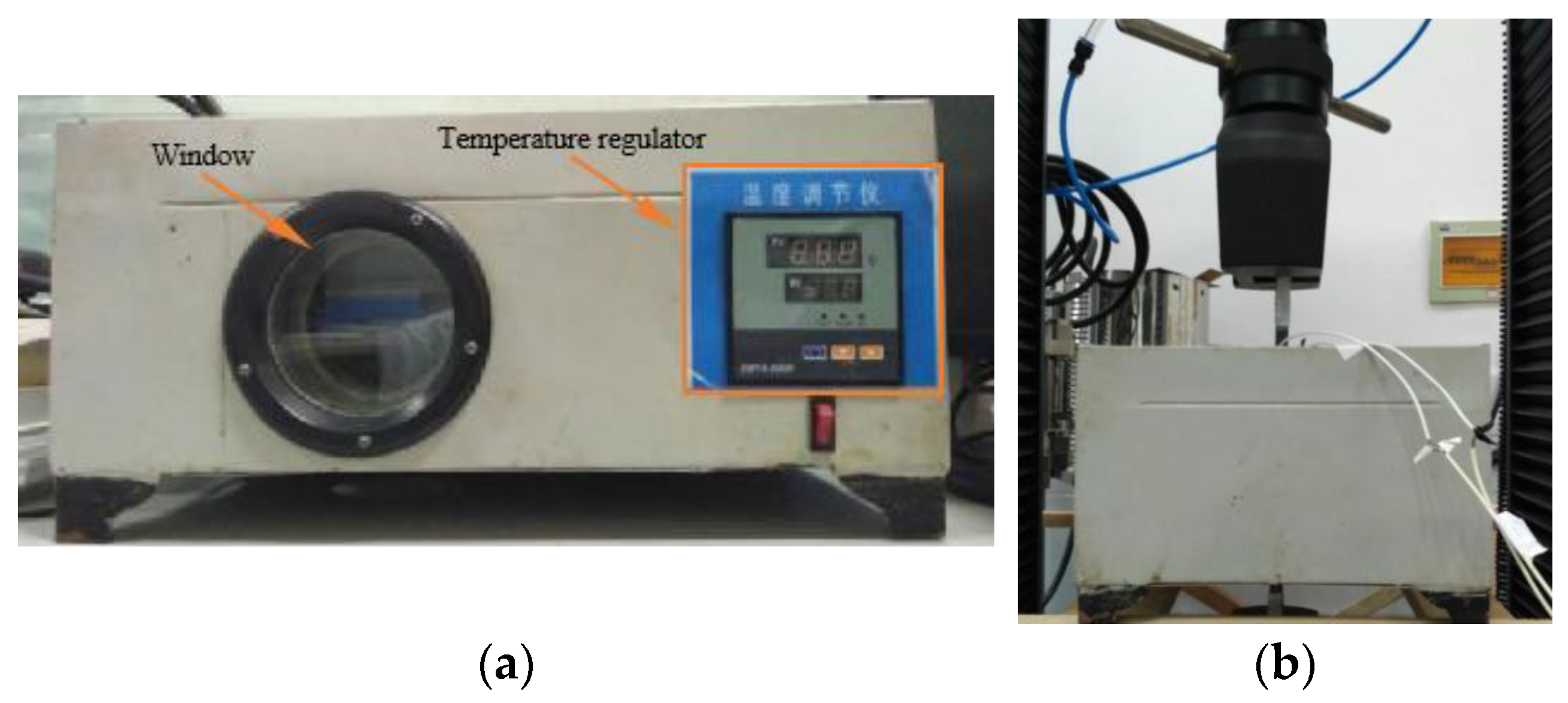
The specimens were tested in a temperature chamber (see Figure 3a). To ensure the saturation of the entire specimen was maintained at the specified target temperature, the temperature chamber was fixed to the testing machine. The specimen went through the chamber and was then clamped (see Figure 3b). After a thermal soaking process of 20 min, the specimens were tested under tension to failure at a constant displacement rate of 2 mm/min using a 300 kN universal hydraulic testing machine.

2.3. Material Testing of Epoxy Adhesive under Elevated Temperatures

A schematic view of the epoxy adhesive adopted in this study is shown in Figure 4, where the geometry is defined according to GB/T 2567-2008 [25]. All adhesive coupons used for tensile tests were made by pouring a homogeneous mixture into plexiglass molds and curing for 1 week at ambient temperature, as shown in Figure 5. These coupons were divided into five groups and tested under different temperatures (see Table 2).

2.4. Bond Testing of CFRP/Steel Double Strap Joint under Elevated Temperatures

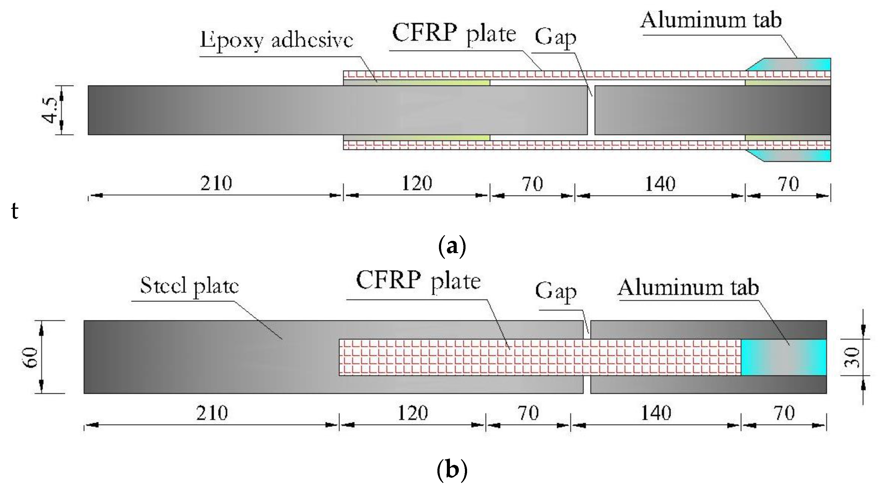
Figure 6 shows the details of the CFRP/steel double strap joint, which includes the internal steel plate, the external CFRP plate, and the adhesive layer in between. The surfaces of the steel plates were sand-blasted and cleaned with acetone to remove grease, oil, and rust. Each steel/CFRP double strap joint was fabricated from two steel plates joined together by CFRP plates. The joints were formed using a wet lay-up method with an adhesive layer thickness ranging from 0.5 to 0.6 mm. All coupons were cured for two weeks under room temperature. A total of 30 coupons were divided into five groups and tested with exposure to 10, 30, 50, 70, and 90 °C, as shown in Table 3.
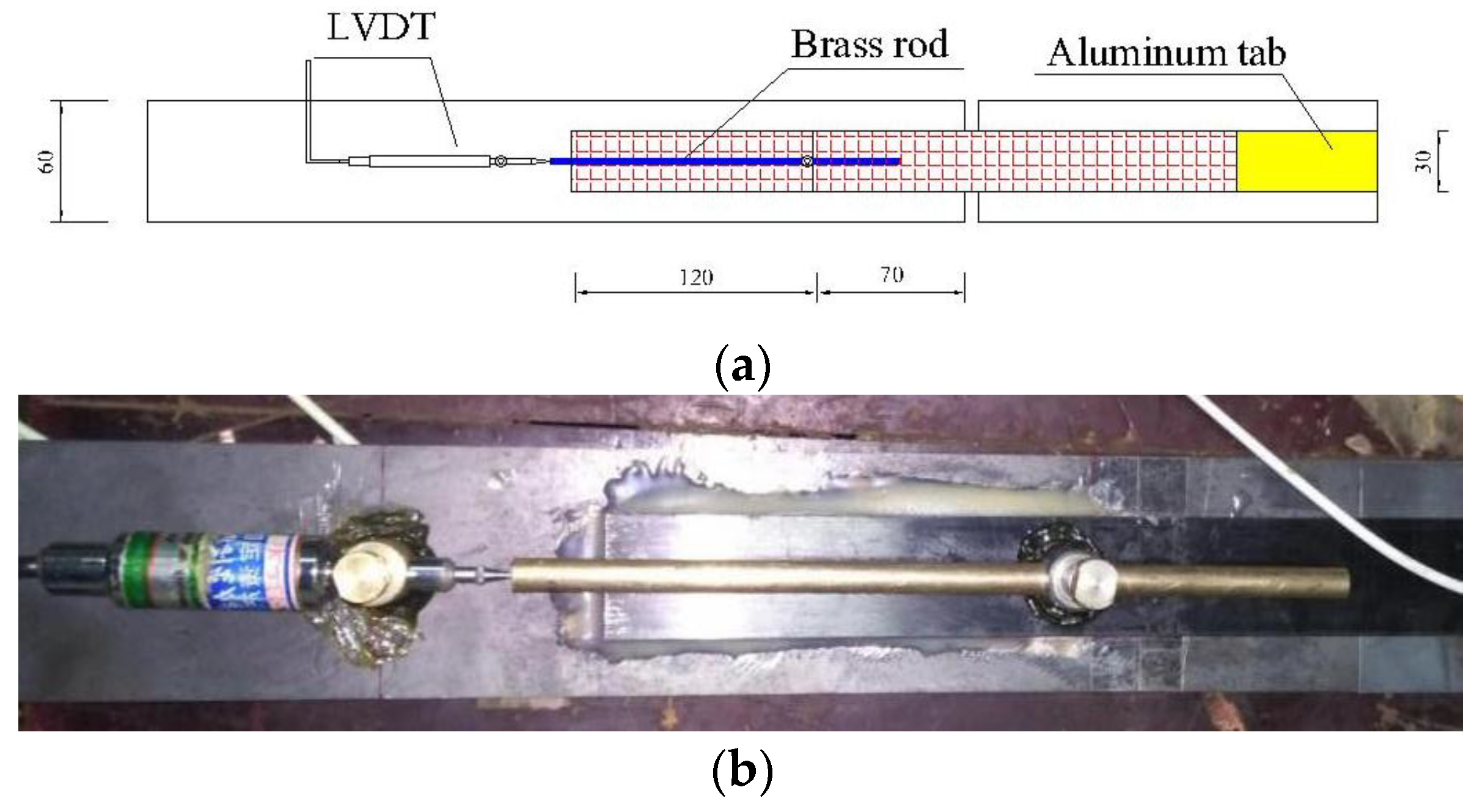
Strain gauges with a working temperature of −30~120 °C were mounted on the top surface of the CFRP plates, as shown in Figure 7. The strain gauges at the extreme locations were bonded at 5 mm from the CFRP loaded end and 15 mm from the CFRP free end. The remaining intermediate gauges were spaced 20 mm apart. A data logger was used to collect the axial strains developed throughout the CFRP plates during the test. As shown in Figure 8, a brass rod was adopted due to its low linear expansion coefficient (1.65 × 10⁻⁵/°C), and the difference between the displacement of the CFRP at the loaded end and the displacement of the steel plate at the point where the brass rod was fixed was calculated. Then, the slip between the loaded end of the CFRP and the steel plates was determined by subtracting the deformation of the steel plates from the measured values.

3. Experimental Results and Discussion

3.1. Effect of Elevated Temperatures on the Properties of CFRP Plates

The test observations and the failure mode changed with different temperatures. For the coupons at 10 °C and 30 °C, several sounds due to the rupture of carbon fibers could be heard when the coupons were very close to failure. When the temperature was 50 °C, more sounds could be heard before failure. As for the coupons exposed to 70 °C and 90 °C, sounds could be heard when the load reached 80~85% of the ultimate load.
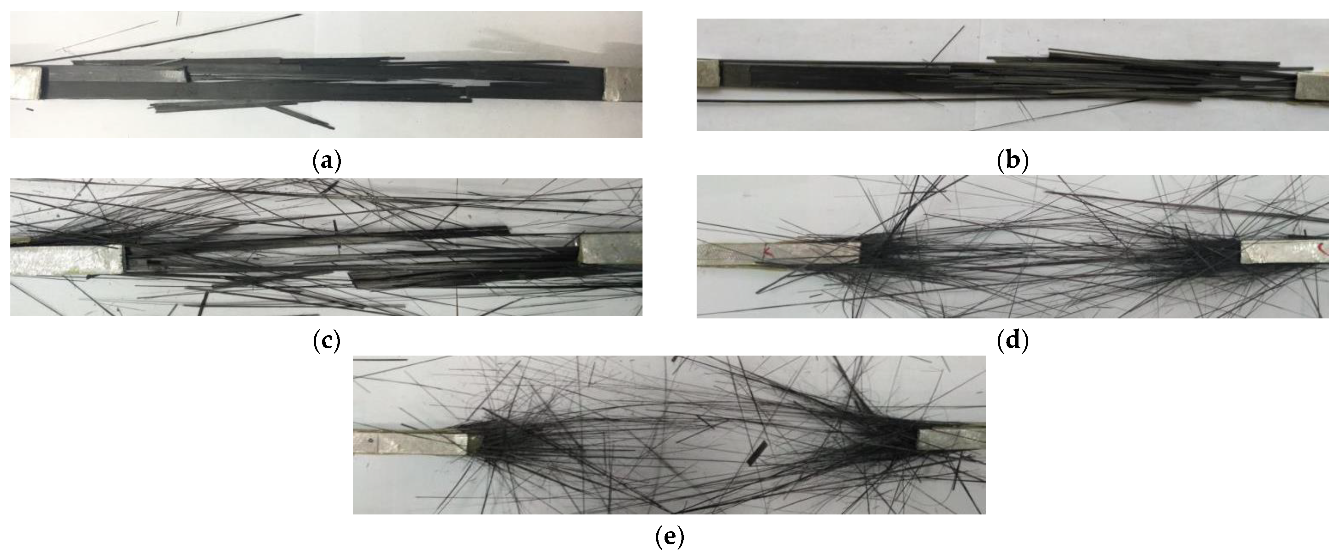
Figure 9 shows the failure modes of the CFRP plate coupons at different temperatures. From Figure 9a,b, it can be seen that the CFRP plates at 10 °C and 30 °C ruptured with several hanks. When the temperatures were 70 °C and 90 °C, the CFRP plates seemed to be separated into a number of CFRP bundles and ruptured explosively, as shown in Figure 9d,e, respectively. These different phenomena can be explained as follows: With the increase in temperature, the epoxy adhesive gradually softened and the shear strength decreased. Consequently, the epoxy adhesive gradually failed to transfer the load between the carbon fibers, and the carbon fibers were stretched until they ruptured and separated.
The test results of CFRP plate coupons are summarized in Table 1. Figure 10 shows the effect of elevated temperature on the properties of CFRP plates in terms of tensile strength. When the temperature increased from 10 °C to 30 °C, the tensile strength and modulus had no change. However, compared with the tensile strength at 30 °C, the ultimate strength of the coupons at 50 °C, 70 °C, and 90 °C decreased by 5.50%, 8.68%, and 9.01%, respectively. The modulus of the CFRP plates experienced a very slight decrease when the temperature increased from 10 °C to 90 °C.

3.2. Effect of Elevated Temperatures on the Properties of Epoxy Adhesive

The epoxy adhesive coupons under different temperatures all ruptured in the middle range, as shown in Figure 11. The difference was that the coupons at higher temperatures experienced a much larger deformation due to softening.
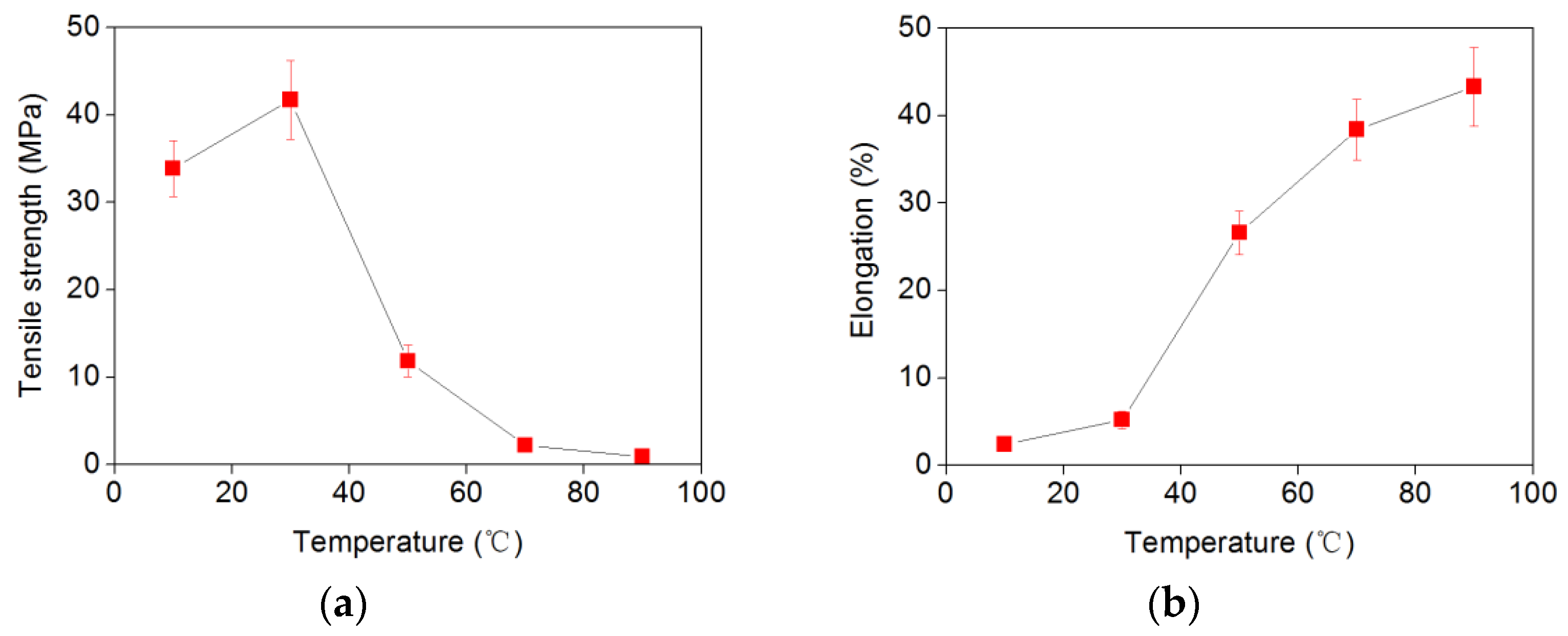
The test results are summarized in Table 2. When the temperature exceeded 50 °C, the modulus of the epoxy adhesive was not measured due to softening and creep. The effects of temperature on the tensile strength and elongation of the epoxy adhesive are shown in Figure 12.
When the temperature increased from 10 °C to 30 °C, there was an obvious increase in the tensile strength. However, with a further increase in temperature, the tensile strength had a sharp decrease, being close to 0 MPa at 90 °C. As for the elongation, there was a slight increase when the temperature was below 30 °C, beyond which the elongation increased significantly. This indicated that the glass transition temperature of the epoxy adhesive was lower than 50 °C.

3.3. Effect of Elevated Temperatures on the Properties of CFRP/Steel Double Strap Joint

3.3.1. Failure Mode

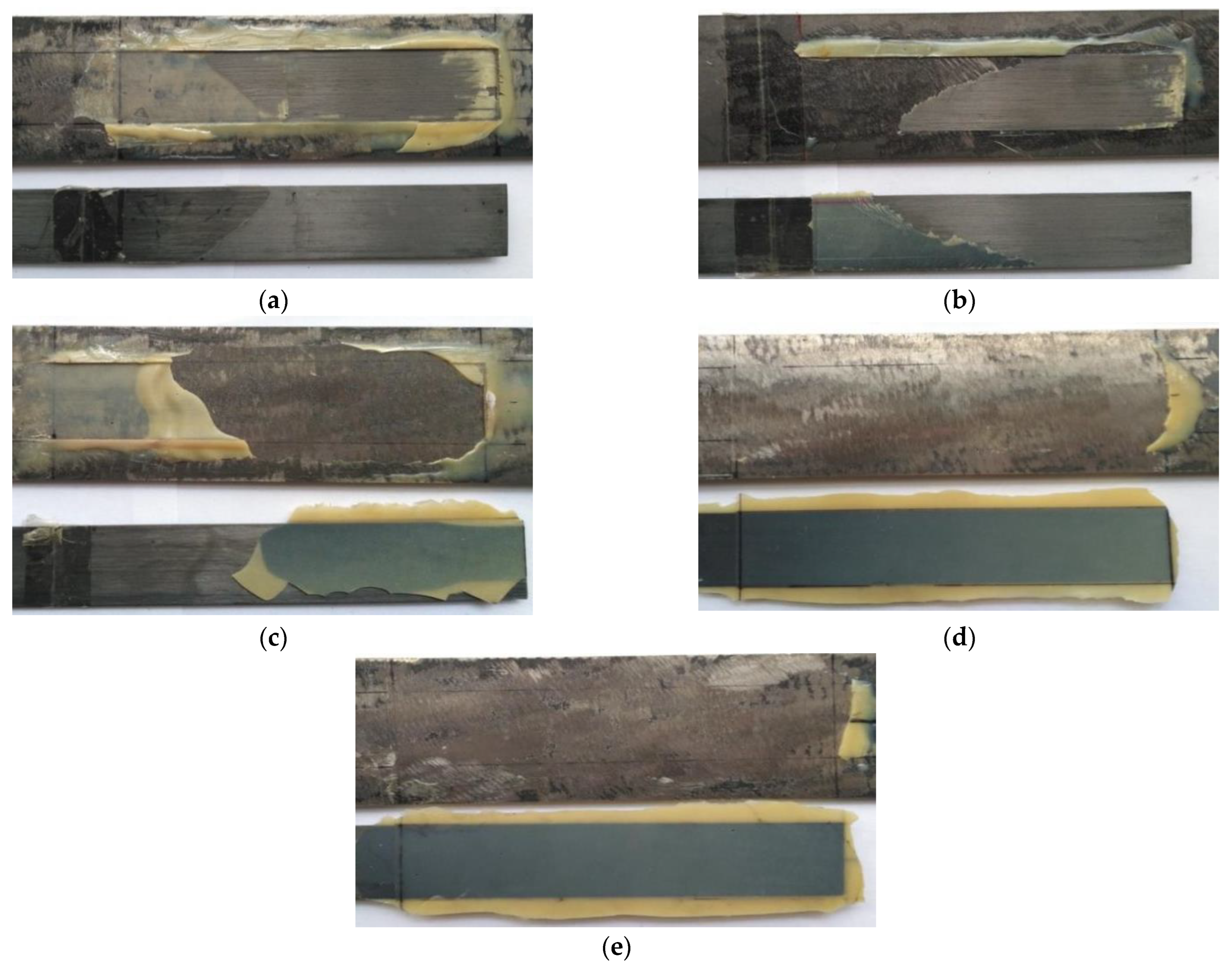
The failure mode of the steel/CFRP double strap joints was categorized into six modes: (a) steel and adhesive interface debonding, (b) adhesive layer failure (cohesive failure), (c) CFRP and adhesive interface debonding, (d) CFRP delamination, (e) CFRP tensile rupture, and (f) steel yielding. Failure modes are shown in Figure 13. At 10 °C, the CFRP plate was entirely separated from the steel plate and there were small amounts of carbon fibers attached to the steel surface, as seen in Figure 13a, i.e., joints failed mainly in mode (c). When temperature increased to 30 °C, the failure of these joints can be defined as mode (d)—CFRP delamination, as shown in Figure 13b. When temperature increased to 50 °C, the joints failed in mode (b), with part of the adhesive attached to the steel plate and part of the adhesive attached to the CFRP plate, as shown in Figure 13c. For the joints at 70 °C and 90 °C, they failed due to debonding between the steel and adhesive, as shown in Figure 13d,e.

3.3.2. Joint Stiffness

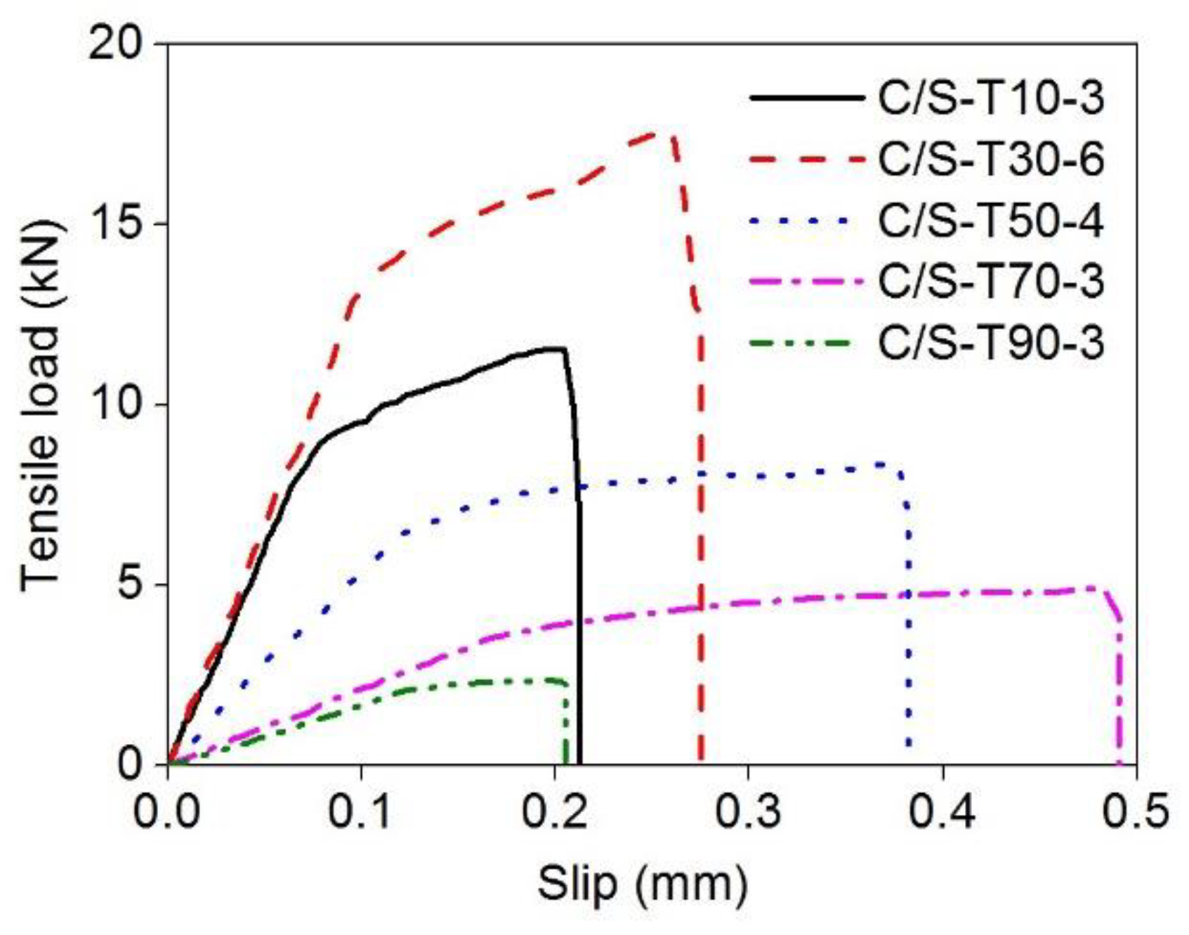
Figure 14 shows the relationship between tensile load and joint displacement for the specimens at different temperatures. Apparently, these curves include two linear stages, and the slope of the first stage is much steeper than that of the second one, after which the load suddenly reduces to zero. In Figure 14, the slope of the curves is found to increase slightly when the temperature increases from 10 °C to 30 °C, and then decrease when the temperature increases from 30 °C to 50 °C and higher values. This indicates that joint stiffness increased first and then decreased with temperature. This stiffness reduction was caused by the stiffness degradation of the adhesive layer, being the weakest link under temperature effects. The values of slip at the ultimate load increase with the increase in temperature.
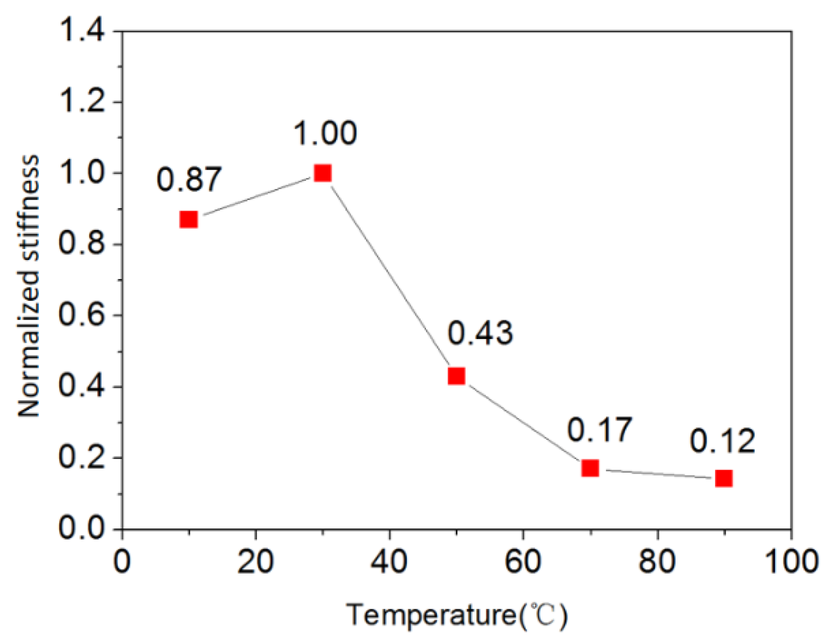
The stiffness of each joint at different temperatures was normalized to that at 30 °C, i.e., dividing the slope of the load displacement curve at different temperatures by that at 30 °C, as shown in Figure 15. A much faster decrease can be observed when the temperature increases from 30 °C to 50 °C. The joint stiffness is reduced by 57% when the temperature increases from 30 °C to 50 °C. This is because when the temperature is around or above the glass transition, the shear modulus and the elastic modulus both degrade with the same trend. The degradation of stiffness shown in Figure 15 is mainly caused by the shear deformation of the adhesive layer.
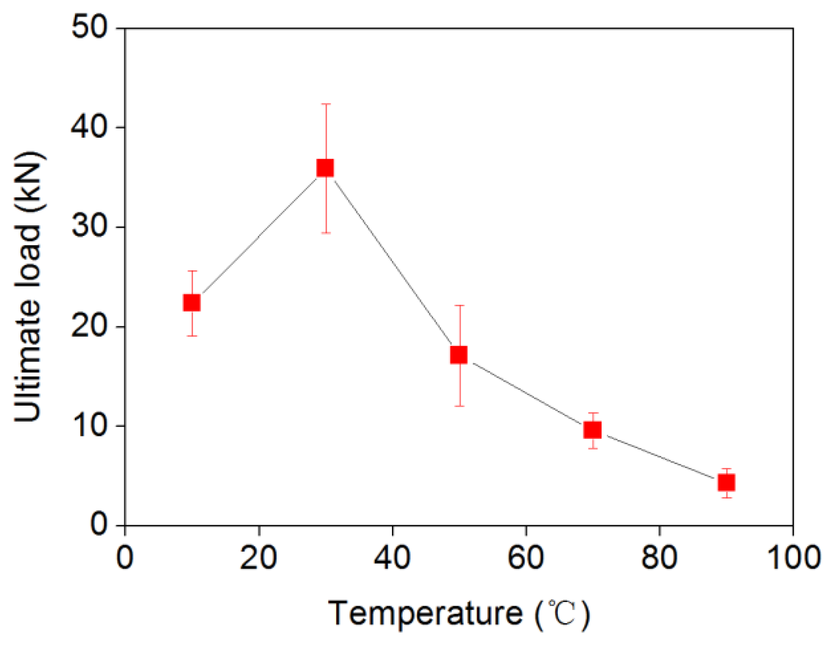
The ultimate tensile load of the joint under different temperatures is shown in Figure 16, in which the values are given as an average load of the six specimens in each group. Apparently, the ultimate tensile load increased first and then decreased sharply with the increase in temperature. The CFRP/steel double strap joints at 30 °C obtained the highest value (36 kN). When the temperature increased to 50 °C, the ultimate load experienced a 52.1% reduction compared with that at 30 °C. At 70 °C and 90 °C, the ultimate load dropped by 71% and 88%, respectively.

3.3.3. Strain Distribution

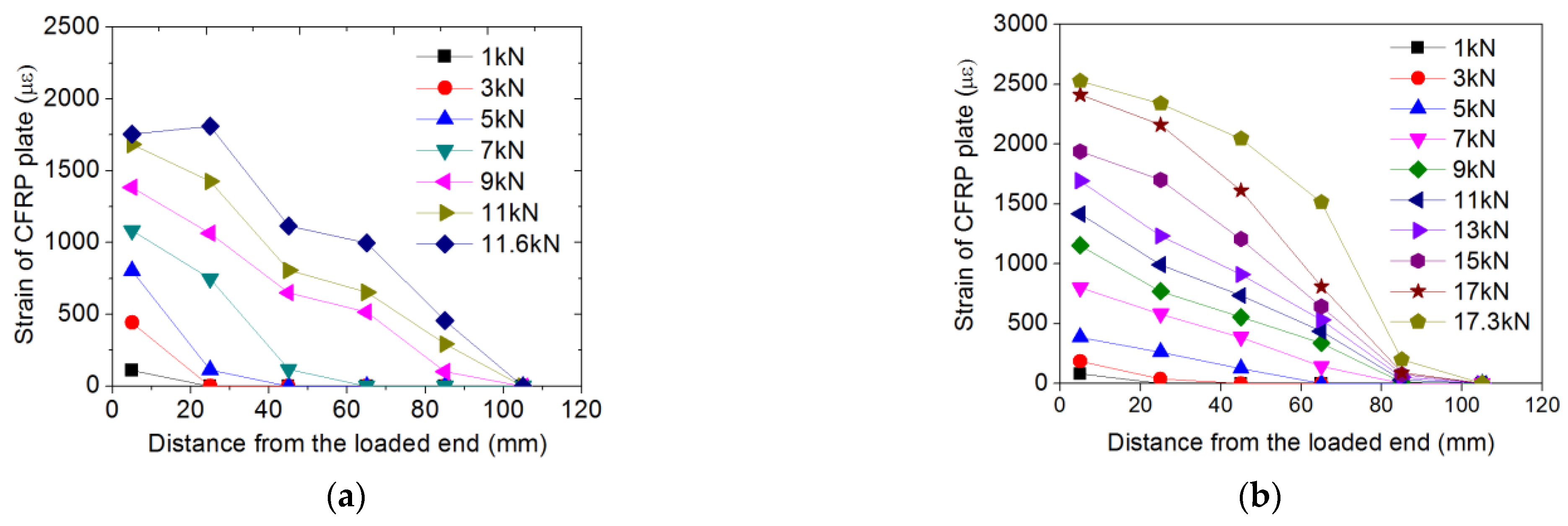
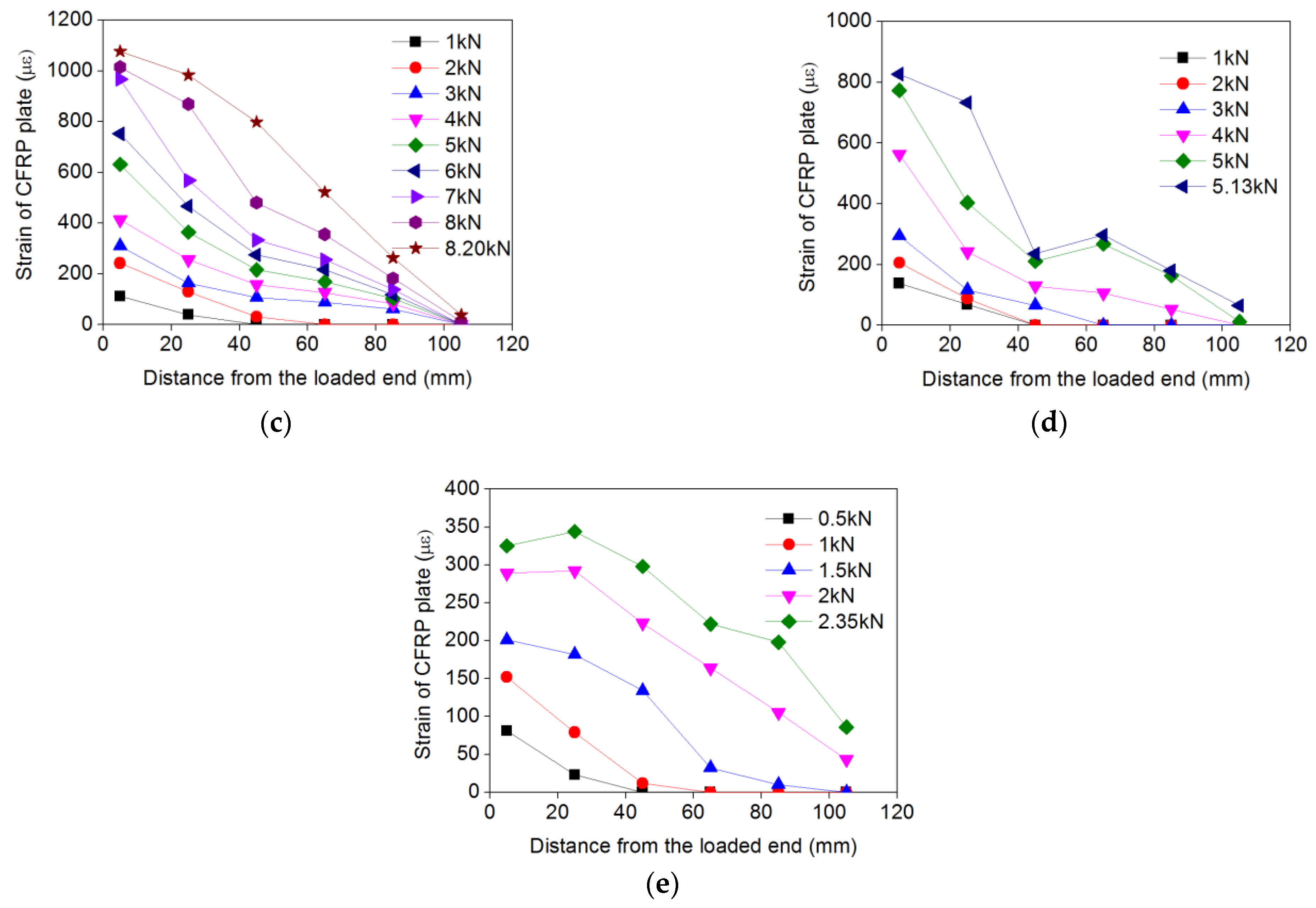
The strain distribution of the CFRP plate at different load levels is presented in Figure 17. The strain of the CFRP plate decreased with the increase in distance from the loaded end. With the increase in tensile load, the load was gradually transferred towards the free end. For the specimens at 10 and 30 °C, the strains at the ultimate load were still zero; this means that the effective bond length was less than 115 mm and more than 85 mm. However, for the specimens at 70 and 90 °C, the strains at the ultimate load were higher than zero, which indicates that the effective bond length was more than 115 mm. Thus, it can be concluded that the effective bond length increased with temperature. In addition, the strain in the CFRP plate decreased significantly with elevated temperature.

3.3.4. Bond–Slip Curves

To predict the bond stress at any point along the CFRP plate, the applied tensile load and the slip at the loaded end are used to calculate the bond stress–slip by Dai et al. [26]. According to [26], at any location of a bond interface under the boundary condition of zero free end slip, there exists a unique τs relationship and a unique relationship between the strain of FRP sheets and interfacial slip. The relationship between the strain in the CFRP plate at any point and the slip at this point can be expressed as follows.
ε = f(s)
where ε is the strain of the CFRP plate at any point and s is the slip between CFRP plate and steel plate at the corresponding point.
The first derivation with respect to x of Equation (1) is
d ε d x = d f ( s ) d s d s d x = d f ( s ) d s f ( s )
For FRP–steel interfaces, the interfacial bond stress at any point is
τ = E f t f d ε d x = E f t f d f ( s ) d s f ( s )
where τ is the bond stress, and Ef and tf are the elastic modulus and the thickness of the CFRP plate, respectively.
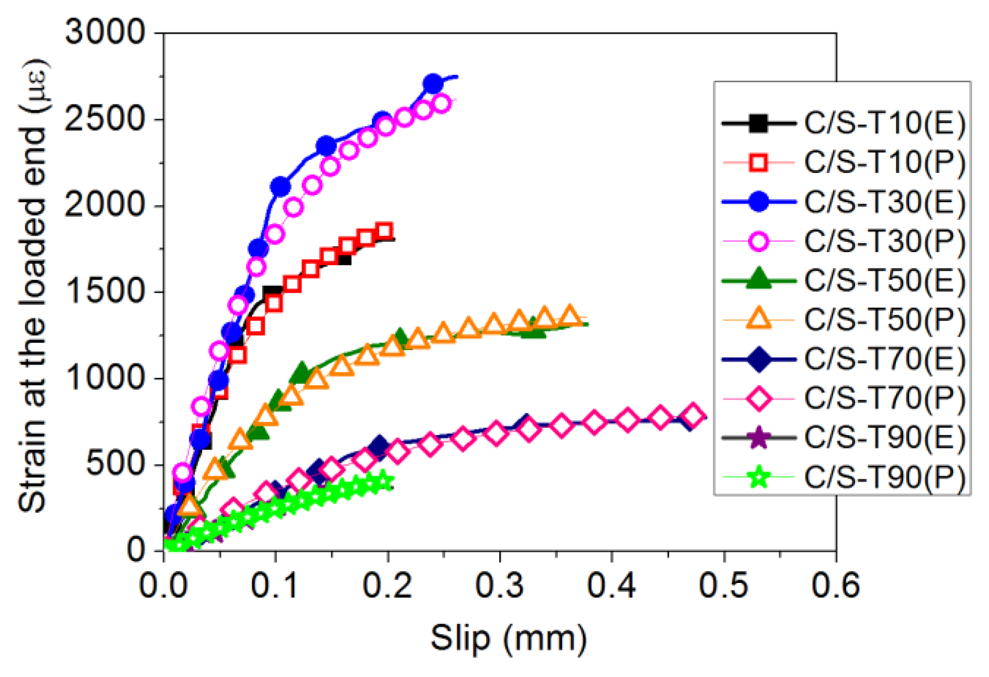
Figure 18 shows relationships between the strain of the CFRP plate and the interfacial slip at the loaded end of the CFRP plate–steel plate concrete interface. It is found that the exponential expression (see Equation (4)) can fit the experimental results very well, as shown in Figure 18.
ε = f(s) = A(1 − exp(1 − Bs))
where A and B are coefficients based on the experimental results, as listed in Table 4.
The bond stress–slip relationship can be obtained as follows:
τ T = A T 2 B T E f t f e ( B T s ) ( 1 e B T s )
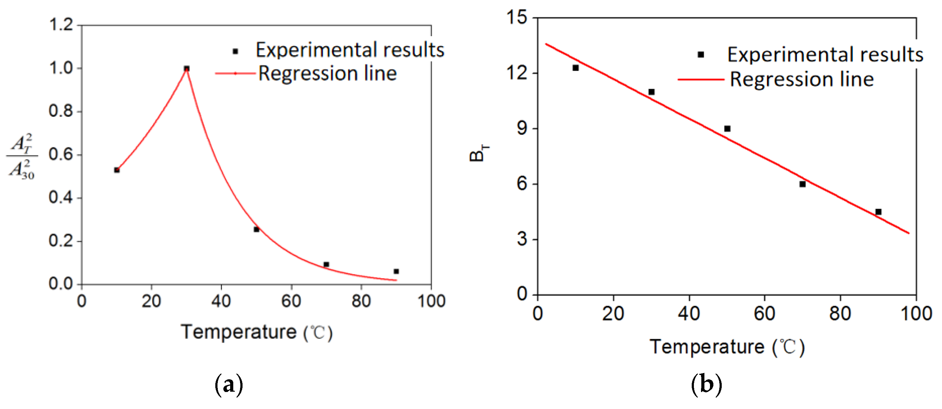
The relationship between the values of A and B and the temperature is shown in Figure 19 and can be expressed as follows.
A T 2 A 30 2 = e K ( T 30 )
B T = 0.107 T + 13.83
where τT is the bond stress considering the elevated temperatures, AT and BT are the coefficients considering the elevated temperatures based on the experimental results, K = 0.0317, if 10 T < 30 ; K = 0.0643, if 30 T 90 .

4. Conclusions

This paper presents an experimental study on bonding properties between CFRP plates and steel plates to assess the effects of temperature on the bond behavior, including bond strength, stiffness, FRP strain distribution, and failure modes. Based on these results, the following conclusions can be drawn:
(1)
Elevated temperatures had a slight effect on the mechanical performance of CFRP plates. The tensile strength had no change from 10 to 30 °C, while it decreased slightly from 30 to 90 °C. The modulus of the CFRP plates experienced a very slight decrease when the temperature increased from 10 to 90 °C.
(2)
The mechanical properties of epoxy adhesive were sensitive to temperature. The tensile strength increased from 10 to 30 °C, but had a significant decrease from 30 to 90 °C, while the elongation increased when the temperature was below 30 °C, beyond which the elongation increased significantly.
(3)
Elevated temperatures had a pronounced effect on the mechanical performance of CFRP/steel double strap joints. Both the bond strength and stiffness increased from 10 to 30 °C, while they decreased from 30 to 90 °C.
(4)
The specimens under 10 °C showed an adhesive/steel interface debonding, whereas most specimens under 30 and 50 °C showed a mixed failure mode. When the temperature increased from 70 to 90 °C, the failure mode changed to adhesive/steel interface debonding.
(5)
The FRP strain distributions in the overlapping area at different levels of load were measured. The effective bond length increased with temperature. In addition, the strains in the CFRP plate decreased significantly with elevated temperature.
(6)
A predictive formula considering elevated temperatures is proposed based on the test results, and the predictions agree well with the test results.

Author Contributions

Conceptualization, N.L.; methodology, N.L.; formal analysis, Y.L. and C.L.; investigation, Y.L. and W.C.; resources, C.L. and W.C.; data curation, C.L.; writing—original draft preparation, Y.L.; writing—review and editing, N.L.; project administration, N.L. All authors have read and agreed to the published version of the manuscript.

Funding

This research was funded by the National Natural Science Foundation of China (no. 52008321).

Institutional Review Board Statement

Not applicable.

Informed Consent Statement

Not applicable.

Data Availability Statement

Data are contained within the article. They are also available on request from the main and the corresponding authors.

Conflicts of Interest

The authors declare no conflict of interest.

References

  1. Teng, J.G.; Yu, T.; Fernando, D. Strengthening of steel structures with fiber-reinforced polymer composites. J. Constr. Steel Res. 2012, 78, 131–143. [Google Scholar] [CrossRef]
  2. Tafsirojjamana, T.; Dogar, A.U.R.; Liu, Y.; Manalo, A.; Thambiratnam, D.P. Performance and design of steel structures reinforced with FRP composites: A state-of-the-art review. Eng. Fail. Anal. 2022, 138, 106371. [Google Scholar] [CrossRef]
  3. Zheng, Z.H.; Du, Y.S.; Chen, Z.H.; Li, S.Y.; Niu, J.Q. Experimental and theoretical studies of FRP-Steel composite plate under static tensile loading. Constr. Build. Mater. 2021, 271, 121501. [Google Scholar] [CrossRef]
  4. Zeng, J.J.; Gao, W.Y.; Feng, L.F. Interfacial behavior and debonding failures of full-scale CFRP-strengthened H-section steel beams. Compos. Struct. 2018, 201, 540–552. [Google Scholar] [CrossRef]
  5. Akbar, I.; Oehlers, D.J.; Ali, M.S.M. Derivation of the bond–slip characteristics for FRP plated steel members. J. Constr. Steel Res 2010, 66, 1047–1056. [Google Scholar] [CrossRef]
  6. Fawzia, S.; Zhao, X.L.; Al-Mahaidi, R. Bond-slip models for double strap joints strengthened by CFRP. Compos. Struct. 2010, 92, 2137. [Google Scholar] [CrossRef] [Green Version]
  7. Al-Shawaf, A.; Al-Mahaidi, R.; Zhao, X.L. Effect of elevated temperature on bond behaviour of high modulus CFRP/steel double-strap joints. Aust. J. Struct. Eng. 2009, 10, 63–74. [Google Scholar] [CrossRef]
  8. ACI 440.2R-08; Guide for the Design and Construction of Externally Bonded FRP Systems for Strengthening Concrete Structures. American Concrete Institute Rep.: Farmington Hills, MI, USA, 2008.
  9. Bai, Y.; Keller, T. Effects of thermal loading history on structural adhesive modulus across glass transition. Constr. Build. Mater. 2011, 25, 2162–2168. [Google Scholar] [CrossRef]
  10. Michels, J.; Widmann, R.; Czaderski, C.; Allahvirdizadeh, R.; Motavalli, M. Glass transition evaluation of commercially available epoxy resins used for civil engineering applications. Compos. Part B Eng. 2015, 77, 484–493. [Google Scholar] [CrossRef]
  11. Kodur, V.K.R.; Bisby, L.A.; Green, M.F. Preliminary guidance for the design of FRP-strengthened concrete members exposed to fire. J. Fire Prot. Eng. 2007, 17, 5–26. [Google Scholar] [CrossRef]
  12. Porter, M.L.; Harries, K. Future directions for research in FRP composites in concrete construction. J. Compos. Constr. 2007, 11, 252–257. [Google Scholar] [CrossRef]
  13. Heshmati, M.; Haghani, R.; Al-Emrani, M. Durability of bonded FRP-to-steel joints: Effects of moisture, de-icing salt solution, temperature and FRP type. Compos. Part B Eng. 2017, 119, 153–167. [Google Scholar] [CrossRef] [Green Version]
  14. Stratford, T.J.; Bisby, L.A. Effect of Warm Temperatures on Externally Bonded FRP Strengthening. J. Compos. Constr. 2016, 16, 235–244. [Google Scholar] [CrossRef] [Green Version]
  15. Guo, D.; Zhou, H.; Wang, H.P.; Dai, J.G. Effect of temperature variation on the plate-end debonding of FRP-strengthened steel beams: Coupled mixed-mode cohesive zone modeling. Eng. Fract. Mech. 2022, 270, 108583. [Google Scholar] [CrossRef]
  16. Dong, K.; Hao, J.W.; Li, P.; Zhong, C.Q. A nonlinear analytical model for predicting bond behavior of FRP-to-concrete/steel substrate joints subjected to temperature variations. Constr. Build. Mater. 2022, 320, 126225. [Google Scholar] [CrossRef]
  17. Yao, M.X.; Zhu, D.J.; Yao, Y.M.; Zhang, H.A.; Mobasher, B. Experimental study on basalt FRP/steel single-lap joints under different loading rates and temperatures. Compos. Struct. 2016, 145, 68–79. [Google Scholar] [CrossRef]
  18. Teng, R.; Guo, Y.; Wang, H.; Zhao, Z.; Wang, X. Experimental study of bending interface characteristics of CFRP-strengthened long-span steel main beams at different temperatures. Eng. Struct. 2021, 235, 111932. [Google Scholar] [CrossRef]
  19. Zhou, H.; Fernando, D.; Torero, J.L.; Torres, J.P.; Maluk, C.; Emberley, R. Bond Behavior of CFRP-to-Steel Bonded Joints at Mild Temperatures: Experimental Study. J. Compos. Constr. 2020, 24, 04020070. [Google Scholar] [CrossRef]
  20. Nguyen, T.C.; Bai, Y.; Zhao, X.L.; Al-Mahaidi, R. Mechanical characterization of steel/CFRP double strap joints at elevated temperatures. Compos. Struct. 2011, 93, 1604–1612. [Google Scholar] [CrossRef]
  21. Chandrathilaka, E.R.K.; Gamage, J.C.P.H.; Fawzia, S. Mechanical characterization of CFRP/steel bond cured and tested at elevated temperature. Compos. Struct. 2019, 207, 471–477. [Google Scholar] [CrossRef]
  22. GB/T 3354-1999; Test Method for Tensile Properties of Oriented Fiber Reinforced Plastics. National Standard of the People’s Republic of China: Beijing, China, 1999.
  23. Li, X.J. Study on the Basic Mechanical Properties and Durabilities of FRP-Steel Composites Material. Ph.D. Thesis, Wuhan University, Wuhan, China, 2014. [Google Scholar]
  24. GB/T 228-2002; Metallic Materials-Tensile Testing at Ambient Temperature. National Standard of the People’s Republic of China: Beijing, China, 2002.
  25. GB/T 2567-2008; Test Methods for Properties of Resin Casting Body. National Standard of the People’s Republic of China: Beijing, China, 2008.
  26. Dai, J.G.; Ueda, T.; Sato, Y. Development of the nonlinear bond stress-slip model of fiber reinforced plastics sheet-concrete interfaces with a simple method. J. Compos. Constr. 2005, 9, 52–62. [Google Scholar] [CrossRef]
Figure 1. Schematic view of CFRP plate coupon: (a) front view; (b) side view (unit: mm).
Sustainability 14 15537 g001
Figure 2. Photographs of the coupons: (a) CFRP plate coupon; (b) location of strain gauge.
Sustainability 14 15537 g002
Figure 3. Test setup: (a) temperature chamber; (b) test setup.
Sustainability 14 15537 g003
Figure 4. Schematic view of epoxy adhesive coupon (unit: mm).
Sustainability 14 15537 g004
Figure 5. Photographs of the adhesive specimens: (a) plexiglass mold; (b) adhesive coupons.
Sustainability 14 15537 g005
Figure 6. Schematic view of CFRP/steel double strap joint: (a) front view; (b) side view (unit: mm).
Sustainability 14 15537 g006
Figure 7. The arrangement of the strain gauges in CFRP/steel double strap joint: (a) schema; (b) photograph (unit: mm).
Sustainability 14 15537 g007
Figure 8. The arrangement of the LVDT in CFRP/steel double strap joint: (a) schema; (b) photograph (unit: mm).
Sustainability 14 15537 g008
Figure 9. Failure mode of CFRP plate under different temperatures: (a) C-T10; (b) C-T30; (c) C-T50; (d) C-T70; (e) C-T90.
Sustainability 14 15537 g009
Figure 10. The effect of temperature on properties of CFRP plate: (a) tensile strength; (b) modulus.
Sustainability 14 15537 g010
Figure 11. Failure mode of the epoxy adhesive coupon under tension.
Sustainability 14 15537 g011
Figure 12. The effect of elevated temperature on the properties of epoxy adhesive: (a) tensile strength; (b) elongation.
Sustainability 14 15537 g012
Figure 13. Failure modes of CFRP/steel double strap joints under different temperatures: (a) C/S–T10-5; (b) C/S–T30-2; (c) C/S–T50-2; (d) C/S–T70-5; (e) C/S–T90-6.
Sustainability 14 15537 g013
Figure 14. Typical tensile load vs. displacement curves for CFRP/steel double strap joints at different temperatures.
Sustainability 14 15537 g014
Figure 15. Normalized stiffness for CFRP/steel double strap joints.
Sustainability 14 15537 g015
Figure 16. Effect of temperature on the ultimate load of CFRP/steel double strap joints.
Sustainability 14 15537 g016
Figure 17. CFRP strain distribution at different loads: (a) C/S–T10-2; (b) C/S–T30-3; (c) C/S–T50-4; (d) C/S–T70-1; (e) C/S–T90-3.
Sustainability 14 15537 g017aSustainability 14 15537 g017b
Figure 18. Comparison between the experimental results and prediction in terms of strain–slip curves (E: experimental results; P: predictions).
Sustainability 14 15537 g018
Figure 19. Regression line: (a) AT and T; (b) BT and T.
Sustainability 14 15537 g019
Table 1. Details of the CFRP plates and the test results.
Specimen
ID
Number of
Specimens
Temperature
(°C)
Ultimate Load (kN)Tensile Strength
(MPa)
Elastic Modulus
(GPa)
Elongation (%)
C-T1061049.482748177.241.55
C-T3063049.572754177.451.54
C-T5065046.762597176.361.47
C-T7067045.282515176.031.43
C-T9069045.022501175.651.41
Note: The specimens were named C(CFRP)-working temperature.
Table 2. Details of the adhesive coupons and the test results.
Specimen
ID
Number of SpecimensTemperature
(°C)
Ultimate Load (N)Tensile Strength
(MPa)
Elastic Modulus
(MPa)
Elongation
(%)
A-T10610135433.8547882.4
A-T30630166941.7250525.2
A-T5065047411.8526.6
A-T70670892.2338.4
A-T90690380.9543.3
Note: The specimens were named A(adhesive)-working temperature.
Table 3. Details of CFRP/steel double strap joint and test results.
Specimen IDTemperature
(°C)
Ultimate Load (kN)Average Value
(kN)
123456
C/S-T101024.023.222.915.925.222.722.35
C/S-T303024.342.534.640.638.634.735.92
C/S-T505020.515.724.916.410.115.217.13
C/S-T707010.211.9.810.16.88.59.58
C/S-T90902.43.84.76.23.05.54.28
Note: The specimens were named C/S (CFRP/steel double strap joint)-working temperature.
Table 4. Coefficients A and B.
Specimen IDTemperature (°C)AB (mm−1)R2
C/S-T10100.00202712.5890.988
C/S-T30300.00278410.8860.951
C/S-T50500.0014118.8490.984
C/S-T70700.0008535.4790.982
C/S-T90900.0006904.5890.969
Publisher’s Note: MDPI stays neutral with regard to jurisdictional claims in published maps and institutional affiliations.