Article

Buck-Boost-Integrated, Dual-Active Bridge-Based Four-Port Interface for Hybrid Energy Systems

by
Anees Vettuparambil
1,
Praveen Raveendran Nair Prasannakumari
2,*,
Walied Alharbi
3,*,
Abdullah S. Bin Humayd
4 and
Ahmed Bilal Awan
5
1
Department of Electrical and Electronics, Halcon Systems LLC., Abu Dhabi 59911, United Arab Emirates
2
Department of Electrical Engineering, College of Engineering, Majmaah University, Al Majmaah 11952, Saudi Arabia
3
Department of Electrical Engineering, College of Engineering, Imam Mohammad Ibn Saud Islamic University, Riyadh 11564, Saudi Arabia
4
Department of Electrical Engineering, Umm Al-Qura University, Makkah 21421, Saudi Arabia
5
Department of Electrical and Computer Engineering, College of Engineering and Information Technology, Ajman University, Ajman 20550, United Arab Emirates
*
Authors to whom correspondence should be addressed.
Sustainability 2022, 14(23), 15555; https://doi.org/10.3390/su142315555
Submission received: 24 September 2022 / Revised: 12 November 2022 / Accepted: 16 November 2022 / Published: 23 November 2022

Abstract

:
A power electronic interface using four ports to interconnect the solar photovoltaic panels, wind generator, battery, and DC microgrid is proposed in this paper. The proposed converter employs a two-winding transformer to interface 380 V of the DC microgrid with all the other three ports, namely, the solar port, wind port, and battery port, which have relatively low nominal voltages. However, the power transfer from solar and wind ports to the battery port bypasses this transformer, thus reducing the potential power losses in the transformer. Furthermore, the maximum and minimum values of the voltage range in which the converter can tap maximum power from solar and wind sources are not constrained by the battery voltage, thus improving the power extraction capability of the multiport converter. The controller for the multiport converter has been developed for extracting the maximum power from renewable sources and to control the charging current of the battery. The simulated response of the converter was studied using the MATLAB/Simulink platform. The simulated response confirms the operation of the converter.

1. Introduction

Electricity is an inescapable resource for the functioning of the modern world. A major part of the world’s electrical energy is produced from fossil fuels and from other conventional energy sources, such as nuclear- or hydroelectric-based power plants, etc. This dependency on the aforementioned sources of energy is a major bottleneck for sustainable development. Since fossil and nuclear fuels are non-renewable sources, their availability cannot be ensured indefinitely. Furthermore, the emission from these fuels is the major contributor to greenhouse gases and other airborne pollutants. These emissions lead to global warming and changes in climatic cycles, and pose a health risk for living beings. In addition, fossil and nuclear fuel deposits are concentrated in only a few locations in the world, and the potential sites for large hydroelectric power plants are limited. Hence, the accessibility of energy from conventional sources is highly constrained.
The generation of electricity from conventional sources is economically viable only if it is produced by setting up large power plants and is distributed through an interconnected power grid. However, many remote localities in the world either do not have access to the electric power grid, or the available grid is unreliable.
The aforementioned issues with conventional energy sources have led researchers to explore the generation of electric energy from renewable energy sources (RESs) such as wind, small hydroelectric plants, solar photovoltaic systems, etc. Furthermore, the generating stations of the RESs can be located near the load centers. This makes RESs a sustainable, locally available, and reliable replacement for conventional energy sources.
The main limitation of the RES system is its intermittency, which leads to the reduced reliability of the electric supply. This reliability is improved when diverse RESs are employed together in a single system. Even then, a continuous power supply cannot be ensured in the system. For improving the reliability of power in a RES-based system, the RESs are operated in conjunction with an energy storage system (ESS). The most generally preferred ESS is the rechargeable battery. Therefore, the generation and storage of electrical energy can be localized in a small geographical area where the electrical loads are located. An electrical network comprising RESs, an ESS, and the local loads are made to operate as a single system. These types of systems have become popular over the years, and are known as microgrids [1,2].
The microgrid can be designed to operate either in alternating current (AC), direct current (DC), or a hybrid of AC and DC. Most of the RESs and ESSs operate in DC supply, whereas all the modern electric loads either operate in DC or have a DC level in their power conversion stages. Hence, DC microgrids are reported to have a higher operating efficiency than AC microgrids for domestic power supply applications [3]. Furthermore, DC supplies are less prone to power quality issues, such as harmonics, phase imbalance, and frequency variation [4]. Therefore, the DC microgrid has become popular over the years, and the widely accepted voltage level for a DC microgrid is 380 V [5].
In order to control the operation of RESs and ESSs, power electronic converters have to be employed between them and the microgrid. These interfaces can be either a set of individual converters or a single multi-port converter (MPC). Between these two options, a multiport system is more advantageous compared to multiple individual converters, due to the reduced number of components, a reduction in converters in the overall power-flow path, and simplicity in implementing a centralized control [6].
Many of the MPCs reported in the literature, such as [7,8,9], have low voltage gain. Therefore, these MPCs cannot be utilized in applications wherein the nominal voltage of the photovoltaic panel and battery is significantly different from 380 V. Depending upon the type of coupling between the ports, high-gain MPCs can be broadly classified into two categories. They are (i) inductor/capacitor-coupled MPCs, and (ii) transformer-coupled MPCs.
In inductor/capacitor-coupled MPCs, the high voltage gain is achieved through either coupled inductors or capacitor-based couplings. The operating principle of the inductor-coupled MPC reported by the authors of [10] is similar to that of a fly-back converter. In order to operate such converters at higher power levels, a significant amount of energy is required to be stored in the magnetic field of the coupled inductor. This requirement makes the design of the coupled inductor a complex task. MPCs that have capacitive coupling employ a capacitive network that acts as a voltage multiplier [11]. Hence, the voltage gain between the ports can be enhanced by increasing the number of stages of the voltage multiplier. At higher power levels, the current flowing through the capacitors increases, but commercially available capacitors do not have a higher current capacity. Therefore, their application is limited to low power levels.
MPCs having a high voltage gain and the capacity to handle high power are realized by employing transformer coupling [12,13,14,15]. The turns ratio of the transformer dictates the voltage gain between the ports. The transformer is operated at a high frequency to reduce its size. In order to achieve transformer coupling among the various ports of an MPC, either a full-bridge converter [16] or a dual active bridge (DAB) converter [17] is employed as its building block.
The quad active bridge (QAB)-based MPC reported by the authors of [18] has four ports, and these ports are coupled through a four-winding transformer. All the ports of this converter have a bidirectional power-flow capability. A triple active bridge (TAB)-based four-port MPC is reported by the authors of [19]. In these types of MPC, a multi-winding transformer is interfaced with either half-bridge [20] or full-bridge [21] converter topologies, which generate high-frequency AC voltages. These types of MPCs are termed multi-winding transformer-couple MPCs. The voltage levels of the RESs and the battery are comparable and, hence, a high-gain stage between them is unnecessary. In addition, in the case of a multi-winding transformer-coupled MPC, the power transfer between the ports for RESs and the battery port is achieved through the transformer. This decreases the overall efficiency.
The power loss that occurs in the case of multi-winding transformer-coupled MPCs during the power flow from the RESs to the battery port can be eliminated by employing a two-winding transformer-coupled MPC [22,23,24,25,26]. These MPCs utilize DAB converters, wherein one of the active bridges of the DAB is modified to incorporate an additional port. This modified bridge of the DAB converter regulates the voltage of these additional ports and also generates a high-frequency AC voltage across the transformer winding. This dual functionality of the bridge might result in the saturation of the transformer, due to DC voltage appearing across the transformer winding. This possibility is eliminated by using a half-bridge topology for the active bridge in the MPCs, as reported in previous works [22,23]. The usage of half-bridge topology restricts the application of this type of MPC for high-power applications as the RMS value of the capacitor current increases with the power delivered. The two-winding transformer-coupled MPCs reported in earlier works [24,25] employ additional switches to introduce a free-wheeling state in the switching cycle, to eliminate the possibility of transformer saturation. This scheme requires additional active switches, which increases the cost. In the two-winding transformer-coupled MPCs reported by the authors of [26], a full-bridge topology is used on both sides of the transformer, and the possibility of saturation of the transformer is eliminated by suitably modifying the switching strategy. However, these MPCs have a boost type of coupling between the RESs and the battery. Hence the operating voltage of the RESs should be higher than the battery voltage.
It can be concluded from the previously described literature survey that the following topics present a research gap in the area of MPC-interfacing solar panel, wind, and battery systems with a DC microgrid.
(a)
Series connections of solar PV modules and of batteries are required to match their operating voltage to the voltage level of the AC microgrid if low-gain MPCs are employed.
(b)
Inductor/capacitor-coupled high-gain MPCs are not suitable for high-power applications.
(c)
In the case of multi-winding transformer-coupled MPCs, the solar port and the battery port, as well as the wind port and battery ports, are coupled through the transformer. This decreases the efficiency.
(d)
In some of the MPCs reported in the literature, the voltage range for which the PV module and wind system can be operated is limited by the battery voltage.
In order to address the aforementioned disadvantages of the power electronic interfaces reported in the literature, a novel four-port interface is proposed in this paper by integrating buck-boost topology into a dual active bridge. The first and second ports are intended to extract renewable energy from a photovoltaic panel and wind generator; these ports are termed solar and wind ports, respectively. The remaining two ports are intended as an interface between a battery storage system and a DC microgrid; these two ports are termed the battery port and DC port, respectively. These two ports are configured with bi-directional power-flow capability.
The DC port of the proposed MPC has a two-winding transformer-based high-voltage gain with respect to the operating voltages of all the other ports. This functionality allows the solar, wind, and battery ports to operate at a lower voltage, while the DC port is connected with a 380 V DC microgrid. However, this two-winding transformer coupling is not present in the power flow path between the solar, wind, and battery ports. This reduces the power loss that occurs while charging the battery with solar and wind power. Furthermore, neither the maximum nor minimum values of the solar port and wind port voltages are constrained by the battery voltage. This increases the range in which the maximum power can be extracted from the respective sources.
The circuit description and switching analysis of the proposed four-port interface are described in Section 2. The mathematical model of the system is developed in Section 3, and the control structure is presented in Section 4. A simulation model of the proposed four-port interface is developed, and the dynamic behavior of the system is investigated for various conditions. The simulated results are discussed in Section 5.

2. The Four-Port Interface

The circuit diagram of the four-port interface for the solar photovoltaic panel, wind generator, battery, and 380 V microgrid is depicted in Figure 1. There are eight IGBT switches that are organized to form two IGBT bridges. One bridge is connected to the primary side, while the second bridge is connected to the secondary side of a two-winding transformer. The active bridge at the primary side of the transformer is composed of switches S1, S2, S3, and S4, and this bridge is connected to the solar, wind, and battery ports through two inductors, Lpv and Lw. The IGBT switches, S5, S6, S7, and S8 form the secondary side bridge. The DC-link of this bridge acts as the DC port of the MPC at which the 380 V DC microgrid is interfaced.
The switching frequencies of all the IGBTs present in the MPC are selected to be equal and are represented as Fs in the switching-time diagram provided in Figure 2. Any two IGBTs connected in a series to form a leg, such as S1 and S2, are switched in a complementary fashion. That means that when S1 is ON, S2 is set at OFF, and vice versa. Similarly, when S3 is ON, S4 is set at OFF, and vice versa. The complementary operation of switches is applicable to the switches present on the secondary side of the transformer as well. Among those switches, when S5 is ON, S6 is set at OFF, and vice versa. Similarly, when S7 is ON, S8 is set at OFF, and vice versa. The total time period in which a switch is set at ON, as a ratio of the total switching time period, is termed its duty ratio. The duty ratio of S1 is represented as DPV and that of S3 as Dw. The phase angle between the switching sequences of S3 and S1 is 180°, as shown in the switching-time diagram detailed in Figure 2.
When S1 is ON, the voltage across the inductor Lpv is the solar port voltage, Vpv, and when S1 is OFF, this voltage is Vb, the battery voltage. As illustrated in Figure 2, the switch S1 is ON for the D1Ts duration and is OFF for the (1 − D1)Ts duration. By applying the principle of volt–sec balance across Lpv:
V p v D p v T s = V b ( 1 D p v ) T s   .
By rearranging Equation (1), a relationship is developed for the operating voltage of the solar port, as provided in Equation (2). Similarly, by applying the volt–sec balance principle for the inductor, Lw, the relation for the operating voltage of the wind port, Vw, is derived, as given in Equation (3):
V p v = V b 1 D p v D p v
V w = V b 1 D w D w   .
From these two equations, it can be concluded that the solar port voltage and wind port voltage can be controlled by varying the duty ratios, Dpv and Dw, respectively. The relations further reveal that both the solar and wind ports can operate with a voltage from below Vb to above Vb.
In addition to controlling the solar and wind port voltages, the aforementioned switching action of the primary-side bridge generates an AC voltage, vab, across the primary side of the transformer, as depicted in Figure 2. The IGBT bridge connected to the secondary winding is switched as a conventional square wave inverter by operating the switches at a 0.5 duty ratio. Hence, a high-frequency AC voltage, vpq, is generated at the secondary side of the transformer. The switching action of bridges at the primary and secondary sides of the transformer is phase-shifted by an angle of φ, as shown in Figure 2. The equivalent circuit of a transformer for such an operation is shown in Figure 3.
In this equivalent circuit, only the total leakage inductance of the transformer referred to its primary side, Lp is considered, while all other components are neglected. From this circuit, the average power, Ptr, that is transferred from the primary to the secondary side of the transformer and, hence, to the DC port, is derived as given in Equation (4), where n is the number of turns present in the secondary winding of the transformer, as a ratio of the number of turns in the primary winding. In Equation (4), Vab1 and Vpq1 are the fundamental components of primary and secondary side voltages; hence, Ptr accounts only for the power transferred due to the fundamental components. The power transferred due to higher-order harmonics in transformer voltage is neglected, due to the square wave nature of the voltages; furthermore, the leakage inductance offers higher impedance for higher-order harmonics.
P t r = V a b 1 V p q 1 2 π n F s L p s i n ( φ )
From Equation (4), it is clear that the power drawn from, or fed to, the DC port can be varied by controlling the value of φ. This control can either be used to control the DC port current directly, or it can be employed to control the battery current indirectly. Since battery current control is more important than the DC port current control, the control system is designed using the latter method, as described in the next section. Once the solar power and wind power are regulated to the maximum value using duty-ration control, the battery power is controlled via a phase-shift control; then, the balance power is compensated by drawing appropriate power from the DC microgrid through the DC port.

3. Mathematical Modeling

A mathematical model of the converter is necessary to systematically analyze the dynamic behavior of the system and, thereby, to design its closed-loop controllers. The conventional modeling of power electronic circuits, involving the averaging of state variables over a switching cycle, cannot be implemented for the proposed interface as this averaging always results in zero transformer current. Furthermore, the modeling method proposed by the authors of [27] for a DAB converter cannot be implemented in the proposed four-port interface since transformer currents follow unrelated trajectories during the different half-cycles. Therefore, a modeling technique involving the average value of DC variables and the fundamental component of AC variables [28,29] is employed; this technique is called the first component approximation (FCA) method.
To make the modeling process simpler, both the solar and wind ports are assumed to have the same nominal voltage and power rating, so that the following assumptions can be made.
v p v = v w = v r
D p v = D w = d
C p v = C w = C r
L p v = L w = L
i L p v = i L w = i l
The combined renewable port, with an operating voltage of vr, is modeled using the Thévenin method [30], with a voltage of Vth and a resistance of Rth. The inductors Lpv and Lw are assumed to have the same resistances, RL. The total winding resistance of the transformer referred to as its primary is taken as Rp.
Each power electronic switch, Sn, of the MPC is modeled by a time-varying switching function, sn(t), which is given by:
s n ( t ) = { 1 , w h e n t h e s w i t c h i s O N 0 , w h e n t h e s w i t c h i s O F F   .
The circuit equations of the MPC can be expressed in terms of switching functions, as follows.
C r d v r d t = V t h V r R t h s 1 ( i L p v + i t r ) s 3 ( i L w i t r ) L p v d i L p v d t = s 1 v r s 2 V b R L i L p v L w d i L w d t = s 3 v r s 4 V b R L i L w L p d i L p d t = ( s 1 s 3 ) ( V b + v r ) 1 n ( s 5 s 7 ) V d c R p i p C d c d v d c d t = V g v d c R g + 1 n ( s 5 s 7 ) i p
These dynamic equations are piecewise linear. They are converted to a linear form by expressing the state variables and the switching functions in terms of their complex Fourier components. A periodic function, x(t), is represented in complex Fourier form as:
x ( t ) = k = i = x k e j k ω s t
where ωs = 2π/Ts and x k is the kth co-efficient of the Fourier series expansion of x(t), which is described by the relation:
x k = 1 T s x ( t ) e j k ω s t = x k R + x k I
where x k R and x k I   are the real and imaginary parts of x k . In the FCA method [28], only the zeroth and first components of the state variable and the switching functions are considered.
The Fourier coefficients of the switching functions are:
s 1 0 = s 3 0 = d s 2 0 = s 4 0 = 1 d s 1 s 3 1 R = s i n ( 2 π d ) π s 1 s 3 1 I = c o s ( 2 π d ) 1 π s 5 s 7 1 R = 2 s i n ( ϕ ) π s 5 s 7 1 I = 2 c o s ( ϕ ) π
According to the authors of [28], the derivative and product of the complex Fourier components are given by:
d d t x k ( t ) = d d t x k j ω s k x k ( t ) x y 0 = x 0 y 0 + 2 ( x 1 R y 1 R + x 1 I y 1 I ) x y 1 R = x 0 y 1 R + x 1 R y 0 x y 1 I = x 0 y 1 I + x 1 I y 0   .
The dynamic equations for the zeroth component of vr, iL, and vdc, and that for the fundamental component of itr are derived by substituting Equations (14) and (15) into Equation (11). The large-signal model is thereby derived as:
X L S ˙ = A L S X L S + B L S U L S
where:
X L S = [ v r 0 i L 0 i p 1 R i p 1 I v d c 0 ]
A L S = [ 1 R t h C r d C r 2 s i n ( 2 π d ) π C r 2 1 2 c o s ( 2 π d ) π C r 0 2 d L R L L 0 0 0 s i n ( 2 π d ) π L p 0 R t L p 2 π T s 2 s i n ( ϕ ) n π L p c o s ( 2 π d ) 1 π L p 0 2 π T s R t L p 2 c o s ( ϕ ) n π L p 0 0 4 s i n ( ϕ ) n π C d c 4 c o s ( ϕ ) n π C d c 1 R g C d c ]
B L S = [ 1 R t h C r 0 0 0 2 ( 1 d ) L 0 0 s i n ( 2 π d ) π L p 0 0 c o s ( 2 π d ) 1 π L p 0 0 0 V g R g C d c ]
U L S = [ 1 R t h C g 0 0 0 2 ( 1 d ) L 0 0 s i n ( 2 π d ) π L p 0 0 c o s ( 2 π d ) 1 π L p 0 0 0 1 R g C d c ]   .
The small signal model of the system is obtained by introducing a small perturbation in the control variables at their operating points, such that:
d = D + d ˜
φ = Φ + φ ˜   .
The corresponding perturbation in each state variable, x k , is considered as:
x k = X + x ˜ k .  
Using Equations (21)–(23) in Equation (16) results in a non-linear equation, which is linearized using the assumptions made in Equations (24)–(26):
x ˜ k y ˜ = 0
s i n ( 2 π d ˜ ) = 2 π d ˜
c o s ( 2 π d ˜ ) = 0
where y can be any of the control variables, d and φ.
The resulting equations found after applying the approximations provided in Equations (23)–(25) contain the large signal and the small signal terms. The small signal terms on both sides of the equation are equated, to develop a small signal model in the form of:
X ˙ = A X + B U
where:
X = [ v r ˜ 0 ι L ˜ 0 ι p ˜ 1 R ι p ˜ 1 I v d c ˜ 0 ]
A = [ 1 R t h C r D C r 2 s i n ( 2 π D ) π C r 2 1 2 c o s ( 2 π D ) π C r 0 2 D L R L L 0 0 0 s i n ( 2 π D ) π L p 0 R t L p 2 π T s 2 s i n ( Φ ) n π L p c o s ( 2 π D ) 1 π L p 0 2 π T s R t L p 2 c o s ( Φ ) n π L p 0 0 4 s i n ( Φ ) n π C d c 4 c o s ( Φ ) n π C d c 1 R g C d c ]  
B = [ I r C r 0 2 ( V b + V r ) L 0 2 ( V b + V r ) c o s ( 2 π D ) π L p 4 V d c c o s ( Φ ) n π L p 2 ( V b + V r ) s i n ( 2 π D ) π L p 4 V d c s i n ( Φ ) n π L p 0 I d c n C d c ]  
U = [ d ˜ φ ˜ ]   .
The transfer functions of the system, H(s), can be developed from the state-space equation in Equation (27), using the formula H(s) = (sI − A)−1B. However, the expression of H(s) is not derived here since the order of the state matrix is five. The transfer functions and, thereby, the controllers are computed using user-friendly tools that are available in MATLAB.

4. Control Systems

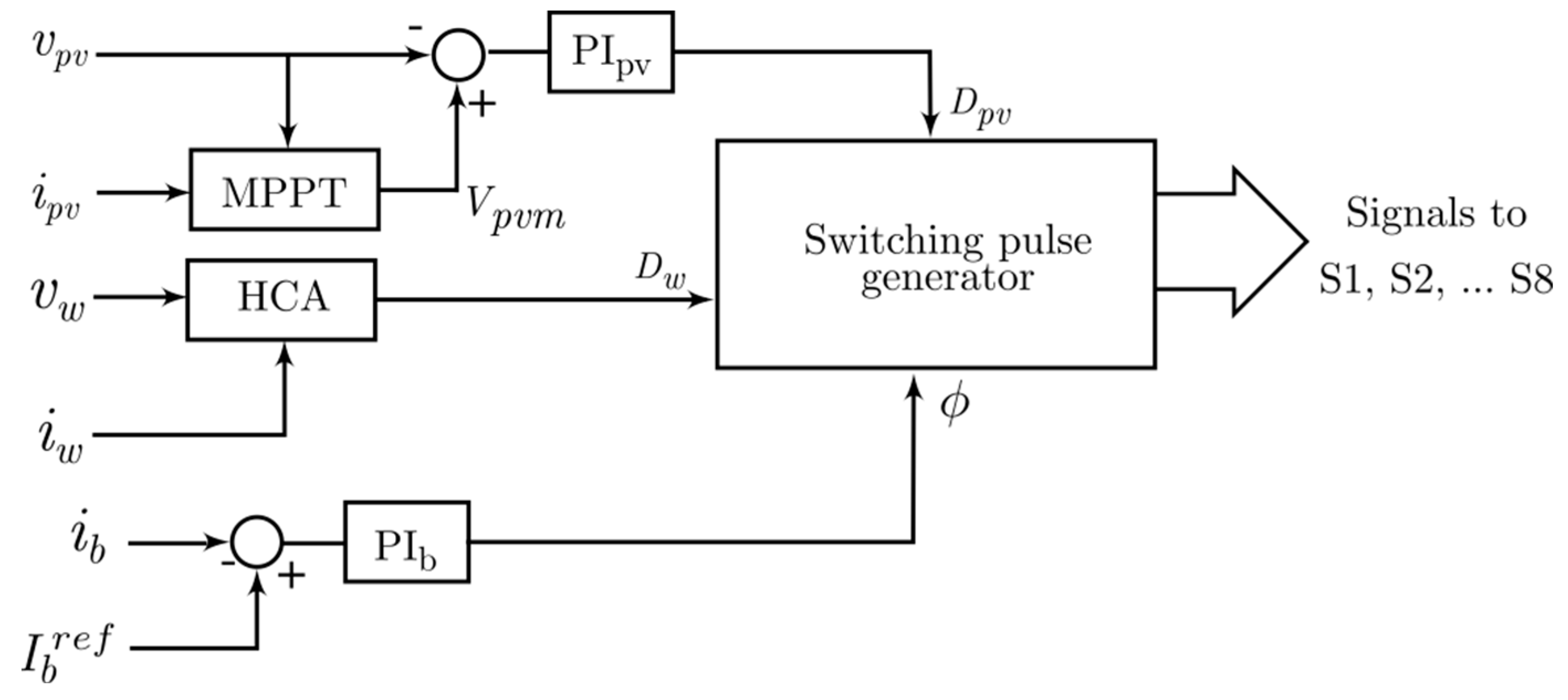
The schematic structure of the control system developed for the proposed MPC is based on PI controllers [31,32] and is depicted in Figure 4. The objectives of the developed control structure are to extract the maximum power from the photovoltaic panel, as well as the wind generator, and to control the battery current. The measured voltage and current, ipv, of the PV module is fed to a solar MPPT algorithm, which is realized using the incremental conductance method. This MPPT block provides the voltage corresponding to the maximum solar power, Vpvm. The voltages Vpvm and Vpv are compared, and their error is amplified using a PI controller, PIpv, which generates the required duty ratio, Dpv.
The maximum power extraction from the wind generator is carried out by employing the Hill-Climbing System (HCS) described in [33]. This system is fed with the voltage and current, vw and iw of the wind port, and directly provides the required duty ratio, Dw as output. The battery current regulation is achieved through phase-shift control where the battery current, Ib is compared with the battery current reference Ibref, and the error is fed to a PI controller, PIb. This PI controller provides the required phase shift angle, Φ. The values of Dpv, Dw, and Φ are fed to a switching signal generator, and accordingly, the switching pulses for all the switches present in the MPC are generated.

5. Simulated Results and Discussion

A simulation model of a renewable energy system based on the proposed MPC is developed in the MATLAB/Simulink platform. A 500 Wp solar panel and 550 Wp wind generator are connected to the MPC. The important parameters employed in the simulated model are provided in Table 1. The simulated model is investigated for changes in the operating environments of the photovoltaic panel and wind turbine, as well as for variations in Ibref.
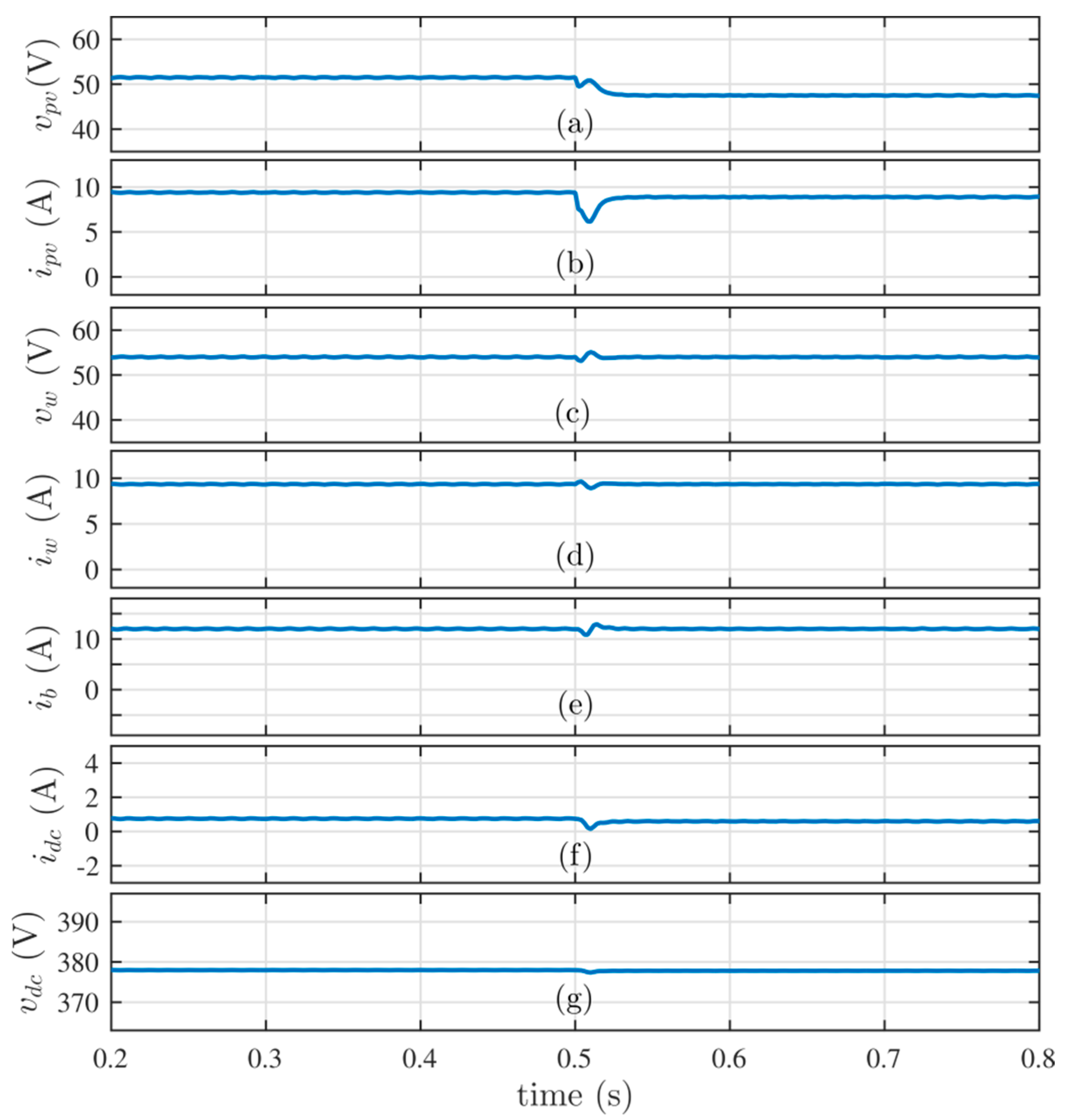
The simulated responses of the system to changes in the environmental conditions of the photovoltaic panel are shown in Figure 5. Initially, the solar panel is subjected to a 25 °C temperature and 1000 W/m2 of solar irradiance. The wind speed is set to 13 knots, while the battery current reference is set to 12 A. It can be seen from the simulated response that the rated power is being extracted from the solar panel and wind generator, while the battery is charged with the set reference. The charging of the battery at this rate leads to a condition where the battery power is less than the power extracted from the renewable sources functioning in the aforementioned environmental conditions. It can be seen from the voltage and current waveforms shown in Figure 5 that the excess power is fed to the grid by having a positive current, idc, at the DC port. At 0.5 s, the operating temperature of the solar panel is increased from 25 °C to 45 °C. From the simulated response shown in Figure 5, it can be seen that the operating voltage of the solar port shifts to a new maximum power point. The reduction in solar power is balanced by reducing the power fed to the microgrid, while the operation of the battery and wind ports is not affected by the variation in temperature of the solar panel.
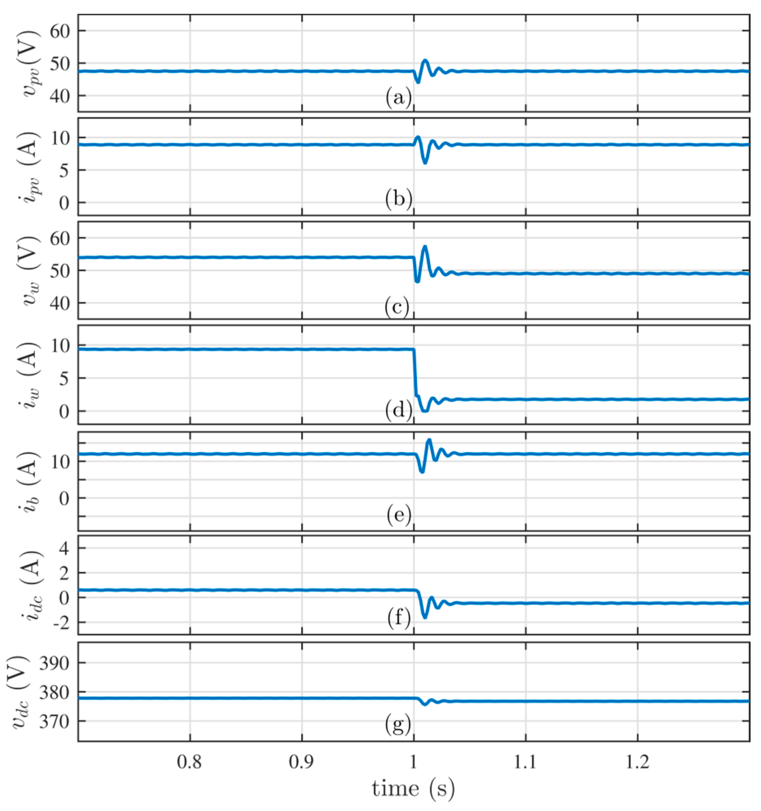
The wind speed is changed from 13 knots to 2 knots at 1 s, and the simulated response of the system is provided in Figure 6. The reduction in wind speed reflects a substantial reduction in the power extracted from the wind generator. However, the operating points of the solar and battery ports are not changed. The decrease in wind power results in a power deficiency condition where the required battery power for its charging at the set reference rate is greater, compared to the total renewable power generated. This power deficiency is compensated for by drawing power from the microgrid through the DC port by reversing the direction of the DC port current, idc.
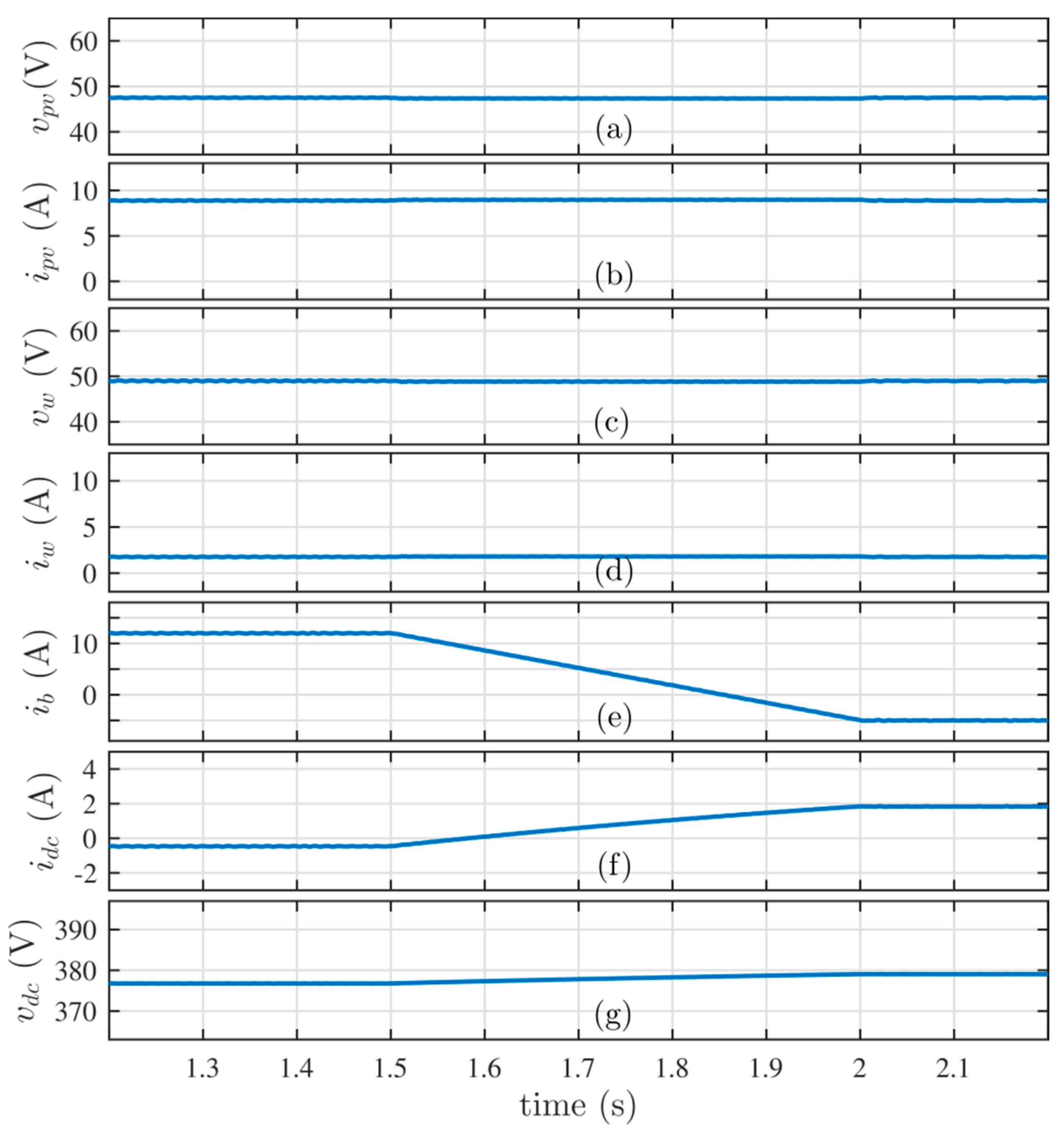
The resultant current and voltage waveforms when Ibref is decreased from 12 A to −5 A in a ramp function from 1 s to 1.5 s are shown in Figure 7. It is evident from the simulation results that the developed control system is capable of regulating the charging rate of the battery current to its set value, along with keeping the operating points of the wind and solar ports at the maximum power points. The negative value of the battery current implies that the battery is discharging. This discharging power, along with the power extracted from renewable sources, is fed to the microgrid, having a positive value of idc.

6. Conclusions

A single-transformer-coupled four-port power electronic interface is presented. These four ports are present in the converter integrating solar and wind energy with a DC microgrid, along with a battery-based energy backup. The DC microgrid will have a relatively higher voltage compared to the operating voltages of the solar, wind, and battery ports, thanks to the high-frequency transformer that is present in the MPC. However, this transformer does not take part in the operations for charging the battery using solar and wind power. This helps to reduce the power loss in the transformer. The solar and wind ports can then have lower as well as higher operating voltages, compared to the battery port. This enhances the range at which the maximum power can be extracted from the respective sources. Along with proposing an MPC having the aforementioned advantages, this paper further contributes regarding other aspects of the MPC, as indicated below:
  • The operation of the MPC is analyzed for various switching intervals, and steady-state relationships for its voltages and power are formulated;
  • A large-signal as well as a small-signal mathematical model of the system has been developed, using the first component approximation method;
  • A control structure is developed to meet the multiple requirements of the system, such as extracting the maximum power from renewable sources and regulating the charging current of the battery;
  • A simulation study is carried out using the MATLAB/Simulink platform, by employing the controller that was designed using the small-signal model.
The simulated results satisfactorily validate the operation of the proposed MPC, including the opportunity for dynamic changes in the system.

Author Contributions

Conceptualization, A.V. and P.R.N.P.; methodology, A.V.; software, P.R.N.P. and W.A.; validation, A.V. and P.R.N.P.; formal analysis, A.V., P.R.N.P. and A.B.A.; investigation, A.V., P.R.N.P. and A.S.B.H.; resources, P.R.N.P., W.A., and A.S.B.H.; data curation, A.V. and P.R.N.P.; writing—original draft preparation, A.V.; writing—review and editing, A.V. and P.R.N.P.; visualization, A.S.B.H. and A.B.A.; supervision, P.R.N.P.; project administration, W.A.; funding acquisition, P.R.N.P., W.A. and A.B.A. All authors have read and agreed to the published version of the manuscript.

Funding

This research was funded by the Ministry of Education of Saudi Arabia, grant number IFP-2020-01, and the APC was funded through IFP-2020-01.

Institutional Review Board Statement

Since this study does not involve humans or animals, there is no need for an Institutional Review Board Statement and its approval number.

Informed Consent Statement

Since this study is not involving humans or animals, there is no need for a Consent Statement.

Data Availability Statement

Not applicable.

Acknowledgments

The Ministry of Education of Saudi Arabia has supported this research work under Grant IFP-2020-01.

Conflicts of Interest

The authors declare no conflict of interest.

Symbols and Abbreviations

ALS, AState matrices in state space representations
BLS, BInput matrices in state space representations
Cpv, CwCapacitors at the input side
CdcCapacitor at the output side
DABDual active bridge
D, Dpv, DwDuty cycles of the primary side switches
ESSEnergy storage systems
FCAFirst component approximation
FsSwitching frequency
HCAHill–Climp algorithm
IGBTInsulated gate bipolar transistor
ipvCurrent from the solar panel
iwCurrent from the wind turbine
iLpv, iLwInductor current
ipTransformer primary current
LpTotal leakage inductance of the transformer referred to the primary
Lpv, Lw, LInductors in the MPC
MPCMulti-port converter
MPPTMaximum power point tracking
nThe turns ratio of the transformer
PIpv, PIwPI controllers
ΦPhase-shift angle between primary and secondary voltage of the transformer
QABQuad active bridge
RESRenewable energy sources
sxSwitching function of switch x
TsTime period of the switching operation
ULS, UInput vectors in state space representations
VbBattery voltage
VpvOperating voltage of the PV panel
VpvmPV voltage corresponding to maximum power
VwOperating voltage of the wind turbine
XLS, XState vectors in state space representations

References

  1. Lasseter, R.H. Microgrids. In Proceedings of the 2002 IEEE Power Engineering Society Winter Meeting, Conference Proceedings, New York, NY, USA, 27–31 January 2002; Volume 1, pp. 305–308. [Google Scholar]
  2. Guerrero, J.M.; Vasquez, J.C.; Matas, J.; de Vicuna, L.G.; Castilla, M. Hierarchical control of droop-controlled ac and dc microgrids—A general approach toward standardization. IEEE Trans. Ind. Electron. 2011, 58, 158–172. [Google Scholar] [CrossRef]
  3. Lee, P.-W.; Lee, Y.-Z.; Lin, B.-T. Power distribution systems for future homes. In Proceedings of the IEEE 1999 International Conference on Power Electronics and Drive Systems, Hong Kong, China, 27–29 July 1999; Volume 2, pp. 1140–1146. [Google Scholar]
  4. Anand, S.; Fernandes, B.G. Optimal voltage level for dc microgrids. In Proceedings of the IECON 2010—36th Annual Conference on IEEE Industrial Electronics Society, Glendale, AZ, USA, 7–10 November 2010; pp. 3034–3039. [Google Scholar]
  5. Decuir, J.; Michael, P. IEEE Draft Standard for DC Microgrids for Rural and Remote Electricity Access Applications. In Proceedings of the 2017 IEEE Conference on Technologies for Sustainability, Phoenix, AZ, USA, 12–14 November 2020; pp. 1–46. [Google Scholar]
  6. Bhattacharjee, A.K.; Kutkut, N.; Batarseh, I. Review of Multiport Converters for Solar and Energy Storage Integration. IEEE Trans. Power Electron. 2019, 34, 1431–1445. [Google Scholar] [CrossRef]
  7. Wu, H.; Xing, Y.; Xia, Y.; Sun, K. A family of non-isolated threeport converters for stand-alone renewable power system. In Proceedings of the IECON 2011—37th Annual Conference of the IEEE Industrial Electronics Society, Melbourne, Australia, 7–10 November 2011; pp. 1030–1035. [Google Scholar]
  8. Ding, S.; Wu, H.; Xing, Y.; Fang, Y.; Ma, X. Topology and control of a family of non-isolated three-port DC-DC converters with a bidirectional cell. In Proceedings of the 2013 Twenty-Eighth Annual IEEE Applied Power Electronics Conference and Exposition, Long Beach, CA, USA, 17–21 March 2013; pp. 1089–1094. [Google Scholar]
  9. Tomas-Manez, K.; Anthon, A.; Zhang, Z.; Ouyang, Z.; Franke, T. High efficiency non-isolated three port DC-DC converter for PV-battery systems. In Proceedings of the 2016 IEEE 8th International Power Electronics and Motion Control Conference (IPEMC-ECCE Asia), Hefei, China, 22–26 May 2016; pp. 1806–1812. [Google Scholar]
  10. Chen, Y.M.; Huang, A.Q.; Yu, X. A High Step-Up Three-Port DC-DC Converter for Stand-Alone PV/Battery Power Systems. IEEE Trans. Power Electron. 2013, 28, 5049–5062. [Google Scholar] [CrossRef]
  11. Prabhala, V.A.K.; Fajri, P.; Gouribhatla, V.S.P.; Baddipadiga, B.P.; Ferdowsi, M. A DC–DC Converter With High Voltage Gain and Two Input Boost Stages. IEEE Trans. Power Electron. 2016, 31, 4206–4215. [Google Scholar] [CrossRef]
  12. Zhao, C.; Kolar, J.W. A novel three-phase three-port UPS employing a single high-frequency isolation transformer. In Proceedings of the 2004 IEEE 35th Annual Power Electronics Specialists Conference, Aachen, Germany, 20–25 June 2004; Volume 6, pp. 4135–4141. [Google Scholar]
  13. Itoh, K.; Ishigaki, M.; Yanagizawa, N.; Tomura, S.; Umeno, T. Analysis and Design of a Multiport Converter Using a Magnetic Coupling Inductor Technique. IEEE Trans. Ind. Appl. 2015, 51, 1713–1721. [Google Scholar] [CrossRef]
  14. Wu, H.; Chen, R.; Zhang, J.; Xing, Y.; Hu, H.; Ge, H. A Family of Three-Port Half- Bridge Converters for a Stand-Alone Renewable Power System. IEEE Trans. Power Electron. 2011, 26, 2697–2706. [Google Scholar] [CrossRef]
  15. Wu, H.; Sun, K.; Chen, R.; Hu, H.; Xing, Y. Full-Bridge Three-Port Converters WithWide Input Voltage Range for Renewable Power Systems. IEEE Trans. Power Electron. 2012, 27, 3965–3974. [Google Scholar] [CrossRef]
  16. Zhu, H.; Zhang, D.; Athab, H.S.; Wu, B.; Gu, Y. PV Isolated Three-Port Converter and Energy-Balancing Control Method for PV-Battery Power Supply Applications. IEEE Trans. Ind. Electron. 2015, 62, 3595–3606. [Google Scholar] [CrossRef]
  17. Kheraluwala, M.N.; Gascoigne, R.W.; Divan, D.M.; Baumann, E.D. Performance characterization of a high-power dual active bridge DC-to-DC converter. IEEE Trans. Ind. Appl. 1992, 28, 1294–1301. [Google Scholar] [CrossRef]
  18. Vishal, M.J.; Nair, A.C.; Fernandes, B.G. Quad-Active-Bridge DC-DC Converter based on-board Power Electronic Interface for Electric Vehicle. In Proceedings of the 2018 IEEE International Conference on Power Electronics, Drives and Energy Systems (PEDES), Chennai, India, 18–21 December 2018; pp. 1–6. [Google Scholar]
  19. Anees, V.P.; Biswas, I.; Chatterjee, K.; Kastha, D.; Bajpai, P. Isolated Multiport Converter for Solar PV Systems and Energy Storage Systems for DC Microgrid. In Proceedings of the 2018 15th IEEE India Council International Conference (INDICON), Coimbatore, India, 16–18 December 2018; pp. 1–6. [Google Scholar]
  20. Wang, L.; Wang, Z.; Li, H. Asymmetrical Duty Cycle Control and Decoupled Power Flow Design of a Three-port Bidirectional DC-DC Converter for Fuel Cell Vehicle Application. IEEE Trans. Power Electron. 2012, 27, 891–904. [Google Scholar] [CrossRef]
  21. Tao, H.; Kotsopoulos, A.; Duarte, J.L.; Hendrix, M.A.M. Transformer-Coupled Multiport ZVS Bidirectional DC–DC Converter With Wide Input Range. IEEE Trans. Power Electron. 2008, 23, 771–781. [Google Scholar] [CrossRef]
  22. Debnath, D.; Chatterjee, K. Two-Stage Solar Photovoltaic-Based Stand-Alone Scheme Having Battery as Energy Storage Element for Rural Deployment. IEEE Trans. Ind. Electron. 2015, 62, 4148–4157. [Google Scholar] [CrossRef]
  23. Su, G.J.; Peng, F.Z. A low cost, triple-voltage bus DC-DC converter for automotive applications. In Proceedings of the 20th Applied Power Electronics Conference and Exposition (APEC-2005), Austin, TX, USA, 6–10 March 2005; Volume 2, pp. 1015–1021. [Google Scholar]
  24. Su, G.J.; Tang, L. A Multiphase, Modular, Bidirectional, Triple-Voltage DC-DC Converter for Hybrid and Fuel Cell Vehicle Power Systems. IEEE Trans. Power Electron. 2008, 23, 3035–3304. [Google Scholar]
  25. Al-Atrash, H.; Tian, F.; Batarseh, I. Tri-Modal Half-Bridge Converter Topology for Three-Port Interface. IEEE Trans. Power Electron. 2007, 22, 341–345. [Google Scholar] [CrossRef]
  26. Ding, Z.; Yang, C.; Zhang, Z.; Wang, C.; Xie, S. A Novel Soft-Switching Multiport Bidirectional DC–DC Converter for Hybrid Energy Storage System. IEEE Trans. Power Electron. 2014, 29, 1595–1609. [Google Scholar] [CrossRef]
  27. Demetriades, G.D. On Small-Signal Analysis and Control of the Single and the Dual-Active Bridge Topologies. Ph.D. Dissertation, KTH Royal Institute of Technology Stockholm, Stockholm, Sweden, 2005. [Google Scholar]
  28. Sanders, S.R.; Noworolski, J.M.; Liu, X.Z.; Verghese, G.C. Generalized averaging method for power conversion circuits. IEEE Trans. Power Electron. 1991, 6, 251–259. [Google Scholar] [CrossRef] [Green Version]
  29. Emadi, A. Modeling and analysis of multiconverter DC power electronic systems using the generalized state-space averaging method. IEEE Trans. Ind. Electron. 2004, 51, 661–668. [Google Scholar] [CrossRef]
  30. Chatterjee, A.; Keyhani, A. Thevenin’s equivalent of photovoltaic source models for MPPT and power grid studies. In Proceedings of the 2011 IEEE Power and Energy Society General Meeting, Detroit, MI, USA, 24–28 July 2011; pp. 1–7. [Google Scholar]
  31. Vallejos, W.D.P. Standalone photovoltaic system, using a single stage boost DC/AC power inverter controlled by a double loop control. In Proceedings of the 2017 IEEE PES Innovative Smart Grid Technologies Conference-Latin America (ISGT Latin America), Quito, Ecuador, 20–22 September 2017; pp. 1–6. [Google Scholar] [CrossRef]
  32. Lema, M.; Pavon, W.; Ortiz, L.; Asiedu-Asante, A.B.; Simani, S. Controller Coordination Strategy for DC Microgrid Using Distributed Predictive Control Improving Voltage Stability. Energies 2022, 15, 5442. [Google Scholar] [CrossRef]
  33. Koutroulis, E.; Kalaitzakis, K. Design of a maximum power tracking system for wind-energy-conversion applications. IEEE Trans. Ind. Electron. 2006, 53, 486–494. [Google Scholar] [CrossRef]
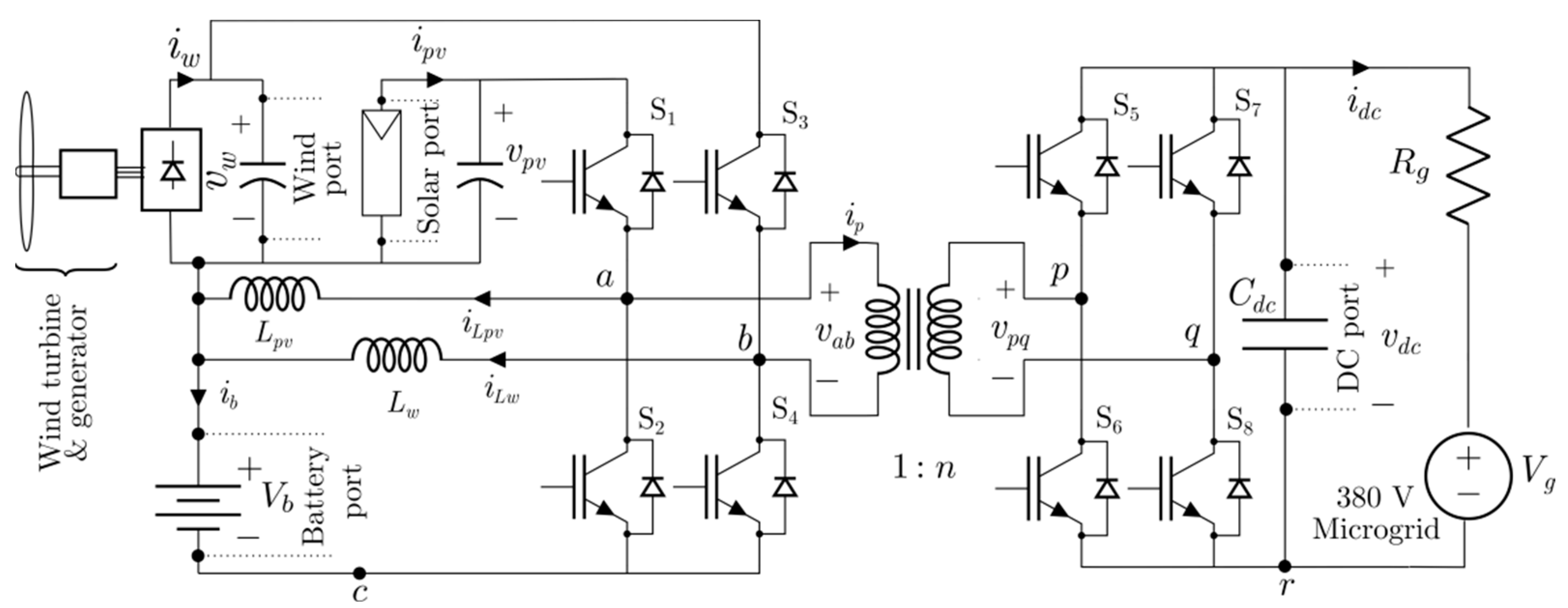
Figure 1. Circuit diagram of the proposed MPC.
Sustainability 14 15555 g001
Figure 2. Waveforms of the key currents and voltages of the MPC during a switching cycle.
Sustainability 14 15555 g002
Figure 3. Equivalent circuit of the transformer present in the MPC.
Sustainability 14 15555 g003
Figure 4. Control structure developed for the MPC.
Sustainability 14 15555 g004
Figure 5. Results of the simulated system when the temperature of the photovoltaic panel is increased at 0.5 s. (a) Solar port voltage, in Volts. (b) Solar port current, in Amperes. (c) Wind port voltage, in Volts. (d) Wind port current, in Amperes. (e) Battery port charging rate, in Amperes. (f) Current fed to the microgrid, in Amperes. (g) DC port voltage, in Volts.
Sustainability 14 15555 g005
Figure 6. Simulated response of the system for a reduction in wind speed at 1 s. (a) Solar port voltage, in Volts. (b) Solar port current, in Amperes. (c) Wind port voltage, in Volts. (d) Wind port current, in Amperes. (e) Battery port charging rate, in Amperes. (f) Current fed to the microgrid, in Amperes. (g) DC port voltage, in Volts.
Sustainability 14 15555 g006
Figure 7. Simulation results for the decrease in battery charging rate from 12 A to −5 A, during the time interval from 1.5 s to 2 s. (a) Solar port voltage, in Volts. (b) Solar port current, in Amperes. (c) Wind port voltage, in Volts. (d) Wind port current, in Amperes. (e) Battery port charging rate, in Amperes. (f) Current fed to the microgrid, in Amperes. (g) DC port voltage, in Volts.
Sustainability 14 15555 g007
Table 1. Values of the parameters employed in the simulation model.
ParameterValue
Fs15 kHz
Cpv, Cw0.4 mF
Lpv, Lw1 mH
Battery voltage48 V
Vpvm at STC51.5 V
Vw at peak power53.2 V
Cdc0.08 mF
Lp40 µH
Publisher’s Note: MDPI stays neutral with regard to jurisdictional claims in published maps and institutional affiliations.