Article

Numerical Simulation Study on Mechanical Characteristics and Width Optimization of Narrow Coal Pillar in Gob-Side Coal Seam Tunnel

1
College of Safety Science and Engineering, Xi’an University of Science and Technology, Xi’an 710054, China
2
Key Laboratory of Western Mine Exploitation and Hazard Prevention Ministry of Education, Xi’an University of Science and Technology, Xi’an 710054, China
3
Xinjiang Coal Science Research Institute, Urumqi 830091, China
4
State Key Laboratory of Gas Disaster Monitoring and Emergency Technology, Chongqing Research Institute, China Coal Technology and Engineering Group, Chongqing 400037, China
*
Author to whom correspondence should be addressed.
Sustainability 2022, 14(23), 16014; https://doi.org/10.3390/su142316014
Submission received: 14 October 2022 / Revised: 10 November 2022 / Accepted: 17 November 2022 / Published: 30 November 2022
(This article belongs to the Collection Mine Hazards Identification, Prevention and Control)

Abstract

:
To investigate the influence of coal pillar width on the stress variation of narrow coal pillar (NCP) in the gob-side tunnel in an inclined thick coal seam, theoretical analysis, numerical modeling, and field monitoring are performed to determine the optimal width of the narrow coal pillars in inclined coal seams. The mechanical characteristics of the NCP for varying widths were investigated. Furthermore, vertical and horizontal stress were calculated for various widths of the NCP. The results revealed that with the rise in the width, the vertical stress initially increased dramatically and then stabilized, whereas the mean horizontal stress increased gradually. The mathematical relation between stress and NCP widths was represented by two fitting equations. The evolution process of the plastic zone in the NCP under various widths and the damage form of various widths were obtained; that is, when the width was small, the position of the roadway near the shoulder corner of NCP was inclined to the top of NCP. The field monitoring data revealed that the optimum NCP width was 4 m. This NCP width could stabilize the roadway and improve the loss prevention of the NCP at the gob-side tunnel of similar mines.

1. Introduction

Coal energy occupies the main position in the Chinese energy structure. With the increase of mining years, the reserves of horizontal coal seams and gently inclined coal seams are dramatically reduced. At present, the focus of mining in China is gradually shifting to inclined coal seams [1,2]. The main reasons for the low recovery rate of coal resources are the limitation of mining technology and the unreasonable width of the protective coal pillar, which causes great waste of coal resources. In addition, compared with the gently inclined coal seam, the inclined coal seam is often accompanied by complex geological conditions, which is easy to cause problems such as roof stress concentration, rock burst, serious roadway deformation, and a more serious waste of coal resources [3,4,5]. In order to solve these problems, domestic and foreign scholars have carried out a lot of research on the theory and technology of narrow coal pillar retention to improve the resource recovery rate.
In view of the characteristics of the NCP size, position, stress change, and the corresponding roadway support technology, researchers conducted in-depth and extensive research using various methods [6,7,8,9]. Wu et al. [10] studied the characteristics of deformation and stress distribution of the NCP under advanced abutment pressure, and the results showed an acceleration in the deep zone of the NCP is larger than that in the shallow zone. Wang et al. [11] found that with the decrease in the distance between the monitoring region and the working area, the shape of the vertical stress core area of the NCP changed from an ellipse to a rectangle. Yang et al. [12] performed a conversion of the double-yield constitutive model, and the results revealed that increasing the NCP size could result in a gradual transformation of the peak stress from the solid coal side to the NCP side. Bai et al. [13] further established the roof destruction criteria and studied the roof bending deformation behavior model. Qi et al. [14] provided a method to support the steadiness of the roadway by using the roof fracture and collapse filling effect, which successfully solved the large deformation problem of the roadway in the process of excavation and panel retreat. Moreover, Some scholars [15,16,17] established models of fracture mechanics and elastic-plastic mechanics to study the stress distribution of strip pillars and the displacement and stress distribution of small pillars in a horizontal coal seam, which provided a theoretical foundation for the NCP stability and control technology of adjoining rock.
In recent years, with the development of DEM models and computational resources, DEMs have been used by scholars to study the crack/damage behavior of the coal pillar [18,19,20]. Zhu et al. [21] used PFC to study the deformation characteristics, failure behavior, and stress distribution of the combined support column (CSP) of the residual coal pillar and filling body, and evaluated its stability. Fu et al. [22] revealed the influence of axial load width and direct roof thickness on the failure mechanism of a notched roof in chamber-pillar mining through experimental tests and numerical simulation. Sarfarazi et al. [23] studied the influence of non-persistent joints and holes on the failure behavior of rock pillars under the uniaxial compression test by using the discrete element method, which provides a reference and method for studying the failure mode strength of NCP in gob-side entry tunnel. Fan et al. [24] and Wang et al. [25] studied the NCP widths of the gob-side tunnel in a horizontal coal seam and established a numerical model for revealing the damage characteristic of the NCP. Fan et al. [26] investigated the weak adjoining rock roadways under substantial mining deformation and established a creep model of anchored adjoining rocks. Zhang et al. [27] combined the support control technique and non-symmetrical control technique for evaluating the gob-side tunnel.
In summary, the current research primarily concentrates on the stability of adjoining rocks and the determination of NCP width along the empty lane driving in horizontal coal seams and gently inclined coal seam. However, the research on the stability and stress features of NCP along the empty lane driving in inclined thick coal seam has not received much attention. Therefore, this paper takes the (4–5) 06 work-face of Liuhuanggou coal mine in Xinjiang as the research object, analyzes the stress and plastic zone variation law under different NCP sizes in inclined thick coal layer, determines the rational NCP width and the key supporting parameters for the gob-side tunnel in an inclined thick coal seam, and verifies the experimental results by field engineering practice, so as to provide guidance for greatly reducing the waste of coal resources and effectively avoiding the disasters caused by in-situ stress, as well as realize the underground safety production and the material and energy saving.

2. Engineering Background

The (4–5) 06 working area of the Liuhuanggou coal mine in Xinjiang province is principally mined in the 4–5 # coal seam in the middle of the lower section of the Xishanyao Formation. The burial depth of the 4–5 # coal seam is 300–600 m, while the burial depth of the gob-side tunnel is 490 m. The mean thickness is 6.15 m, and the dip angle of the coal seam is 24–26°. The direct roof is dominated by thick carbonaceous mudstone (1.35 m) and thick fine sandstone (2.89 m). The basic roof is dominated by siltstone (17.39 m). The rock strata are greyish-white blocks and fine parallel joints, and the upper and middle parts are silt, fine sandstone and mudstone. The floor belongs to argillaceous siltstone (1.85 m). (4–5) 06 working area is 20 m away from the boundary of the minefield, while the east is the protective coal pillar of the auxiliary inclined shaft, the north is the solid coal without mining, and the south is (4–5) 04 gob.
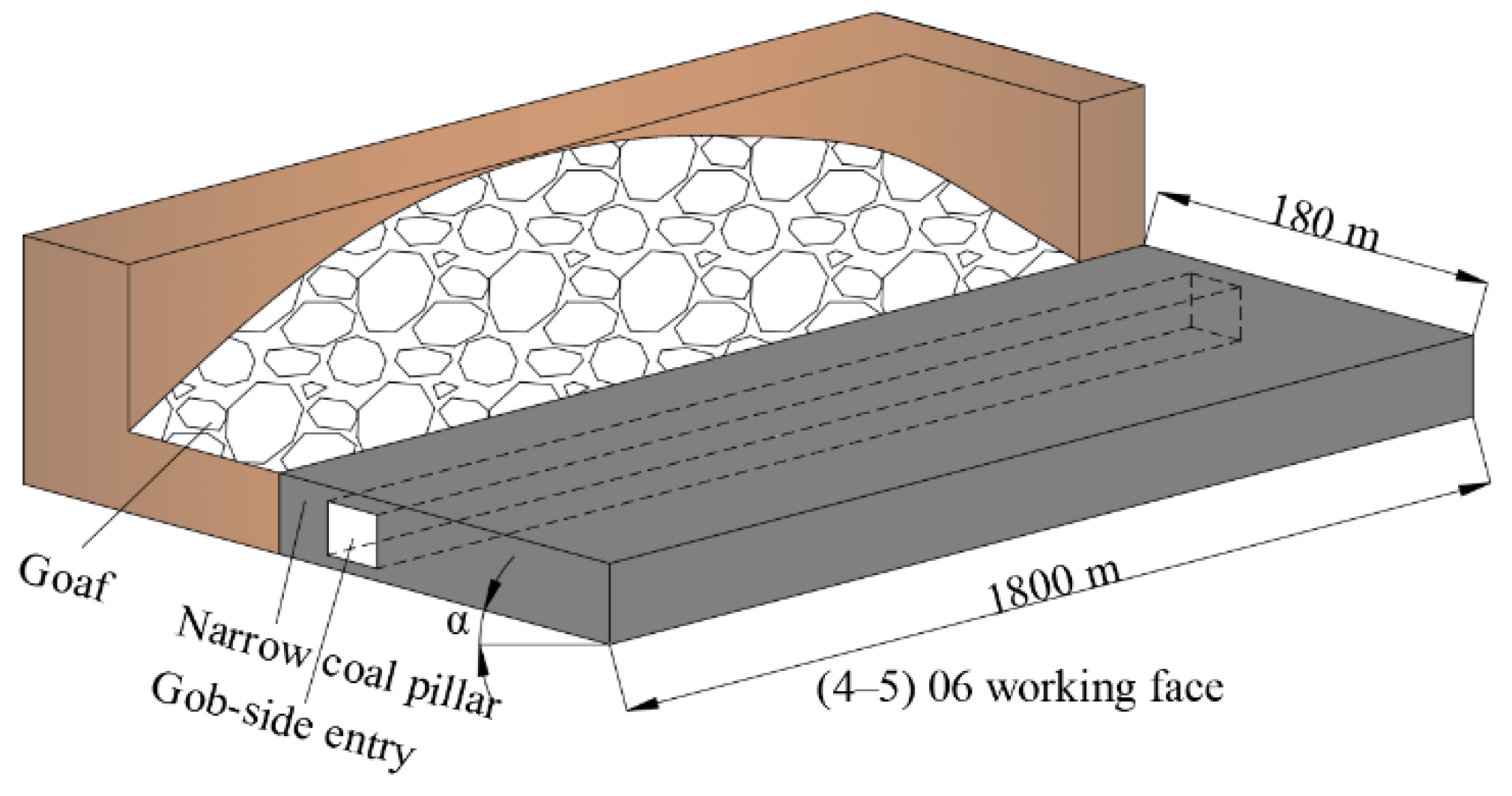
As shown in Figure 1, (4–5) 06 working area inclined length is 180 m, and the strike length is 1850 m. The working area takes once mining full height retreat stoping method. The spatial representation of the gob-side tunnel arrangement in the (4–5) 06 working area is illustrated in Figure 2. The RMT–150C rock mechanics test (Figure 3) was performed on coal and rock to determine the strength of the experimental work face and the lithology parameters of the top and bottom coal seam 4 (Table 1).

3. Experimental

3.1. Analysis of Stress Distribution in Narrow Coal Pillars

The coal seam dip angle and mining thickness are large, and the falling rock refuse and residual floating coal accumulate on the side of the NCP, resulting in lateral pressure on the NCP. Excavating the roadway changes the coal and rock layers, and the state of stress equilibrium will be changed due to both lateral and vertical pressures being acted on the tunnel. To obtain the optimal NCP width (x in Figure 4), the following assumptions are made:
  • The coal body is a homogeneous continuum.
  • The coal strength is the highest in the case of the plain strain.
  • The coal body damaged by shear effects is in accordance with the Mohr–Coulomb criterion [28].
To analyze the stress of adjoining rock of the NCP, a mechanical model of the gob-side tunnel in a thick layer is established, as expressed in Figure 4. In Figure 4, q1 denotes normal pressure on the top of a coal body, MPa; σB annotates the lateral pinching pressure of the key block B, MPa; q2 represents the lateral pressure of the overburden rock on the coal wall in gob area, MPa; θ annotates the rotation angle of the key rock B, °; α expresses the inclination angle of coal layer, °; X0 denotes the distance from the point of the maximum vertical pressure to the coal wall of the gob, m; x indicates the NCP width, m.
Equation (1) can be obtained by solving the stress balance equation at the yield zone interface as below:
{ σ x x + τ xy y + X = 0   ( x   direction ) σ y y + τ xy x + Y = 0   ( y   direction ) τ xy = ( C 0 + σ y tan φ )
where X and Y represent the volumetric force of the coal in the x and y directions in the limit equilibrium zone, MPa; C0 denotes the cohesion force at the interface between the coal layer, roof, and floor, MPa; σx refers to the horizontal stress in the limit equilibrium zone, MPa; σy refers to the vertical stress in the limit equilibrium zone, MPa; τxy expresses the shear stress at the interface between roof and floor, MPa; φ indicates the angle of internal friction between coal layer and rock mass of roof and floor, °.
The solution to the stress point at any point in the limit equilibrium zone is expressed as below [29]:
{ τ xy = { [ 1 A ( P x + γ x 0 sin α ) + 2 C 0 m γ sin α 2 tan φ ] e m A γ cos α 2 tan 2 φ 2 A + 2 tan φ m A + ( 2 tan 2 φ m A γ cos α ) γ tan φ + C 0 σ y = [ 1 A ( P x + γ x 0 sin α ) + 2 C 0 m γ sin α 2 tan φ ] e m A γ cos α 2 tan 2 φ 2 A + 2 tan φ m A + ( 2 tan 2 φ m A γ cos α ) γ
where A represents the constant of lateral pressure; Px denotes the support resistance of the coal, MPa; γ annotates the mean bulk density of the overburden, kN/m3; m refers to the thickness of coal layer, m; α denotes the inclination angle of coal layer, °.
Considering the effect of the coal seam inclination angle and the gob area, the horizontal distance X0 is expressed as follows:
X 0 = m A 2 tan φ ln [ A ( K γ H cos α tan φ + m γ sin α ) A ( 2 C 0 + m γ sin α ) + 2 P x tan φ ]
where K indicates the lateral bearing pressure concentration factor.
Based on elastic-plastic limit equilibrium theory, the optimal NCP width is expressed as follows [30]:
x = ( Z 3 + Z 2 + Z 1 )
Z 1 = m A 2 tan φ ln [ k γ H + C 0 tan φ C 0 tan φ + P x A ]
where Z1 denotes the width of the plastic region in the NCP; Z2 denotes the side bolt’s effective length in the NCP along the empty roadway: 1.2 m. Considering the stability of the NCP, Z3 denotes the coal pillars stability coefficient considering the large thickness of the coal seam (assumed to be 0.2 (Z1 + Z2)); m annotates the thickness of the coal layer: 6.15 m; H refers to the depth of tunnel: 490 m; A represents the constant of lateral pressure: 1.2; K indicates the lateral bearing pressure concentration factor: 2.5; φ denotes the angle of internal friction between the coal layer and rock mass of roof and floor: 12°; C0 represents the cohesion force: 6 MPa; γ expresses the mean bulk density of the overburden: 20 kN/m3; Px refers to the support resistance of coal: 0.3 MPa; and k denotes the safety factor: 1.15–1.45. The parameters are substituted in Equations (3)–(5) to obtain x (4.5 m) and X0 (10 m).

3.2. Establishment of the Numerical Model

(1) Model establishment
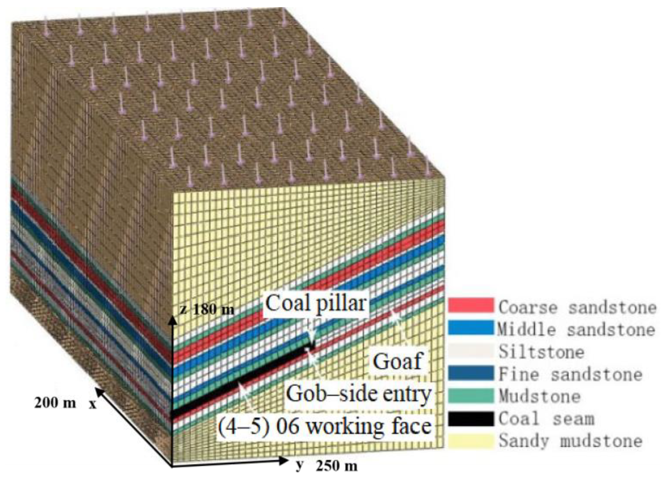
According to the layout of (4–5) 06 working face, a three-dimensional excavation numerical model is established by using ABAQUS4.0 numerical calculation software to analyze the stability of coal pillar and gob-side entry and the variation characteristics of surrounding rock stress under different pillar widths.
The model is established as shown in Figure 5. The model dimension (length × width × height) is determined to be 200 m × 250 m × 180 m, and the dip angle of the coal seam is 25°. In order to eliminate the influence of the boundary effect on the tunneling process of the gob-side tunnel, a 50 m protection boundary is set at both ends of the coal seam strike. The simulated mining length is 100 m, and the simulated dimension (width × height) of (4–5) 06 gob-side tunnel is 4.5 m × 4 m. The initial ground stress was balanced through the initial analysis step calculation.
(2) Mesh subdivision and boundary condition setting
Model boundary conditions are calculated by determining the overburden weight. Based on the actual mining depth of 290 m, a vertical pressure of 106 MPa is applied on the top of the model. The bottom and the four sides were considered to be fixed ends, and the initial ground stress was balanced through the initial analysis step calculation. Finally, the model is meshed, in which the method of over-densification is used to make the mesh density around the coal seam reach 1.
(3) Calculation method and mining scheme
The material failure in the model satisfies the Mohr–Coulomb criterion, and the asymmetric solver method is used for the convergence of the calculation results. The simulation calculation refers to the borehole histogram of the Liuhuanggou coal mine and some laboratory test results, as shown in Table 1.
The numerical analysis of the model was performed in two steps. The first step was gob excavation, and the second step was gob-side tunnel excavation. According to the theoretical width of NPC and the distance from the peak abutment pressure of NPC to the coal wall in goaf, the design scheme of the coal pillar width of 3, 4, 5, 6, 7, 8, 9, 10, 15, 20 m was selected to study the stress variation law of coal pillars with different widths.

4. Results and Discussion

4.1. Vertical Stress Distribution

NCP widths of 3, 4, 5, 6, 7, 8, 9, 10, 15, and 20 m were investigated at a yield zone width of X0 and the NCP width of x (Figure 4). The vertical stress values formed under various NCP widths during roadway excavation are illustrated in Figure 6.
Excavation of the gob-side tunnel changed the stress of the rock masses around the gob area, and a new stress balance state was reached.
The results of numerical analysis, that is, the relation between vertical stress and NCP widths, are illustrated in Figure 7.
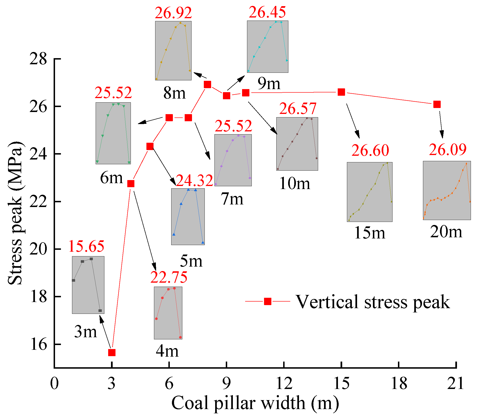
When the NCP width was 3 m, the vertical peak stress was only 15.6 MPa, which was explicitly lower than the primal rock stress. The NCP promptly collapsed under the load because of the absence of a stable bearing area. When the width was 4 m, the stress reached its peak point of 22.8 MPa, and an effective bearing area was formed. The vertical stress was focused at the center of the NCP and was symmetrically distributed. When the width was between 5 and 10 m, the vertical maximum stress increased with the rise in the width. The peak stress position was gradually offset from the center position in the NCP. When the width was 8 m, it reached a maximum of 27 MPa and subsequently stabilized. When the width was between 15 and 20 m, the vertical stress gradually exhibited an asymmetric distribution, and the vertical stress shifted toward the adjacent gob.

4.2. Horizontal Stress Distribution

During the excavation of the roadway, because of the influence of the weight of the overburden and the coal seam pitch, the magnitude, and direction of the force generated by the horizontal force on the NCP changed. The horizontal stress distribution curves on the right side of the NCP under various widths of the gob-side tunnel were determined through numerical calculations (Figure 8).
The following observations were made regarding the horizontal stress distributions for various widths of the NCP:
  • When the width of the NCP increased, the force at both ends of the NCP became more uniform. Therefore, the mean horizontal stress increased. In the NCP, the stress at the bottom was greater than the stress at the top, and the horizontal stress at the two ends was greater than intermediate horizontal stress.
  • The horizontal stress of the NCP first decreased from the bottom to the top and then increased. In the NCP, from the bottom up to one-third of the NCP, horizontal stress alleviated linearly; from one-third to two-thirds length of the NCP, horizontal stress remained unchanged. From two-thirds up to the top, the horizontal stress tended to enhance linearly.

4.3. Vertical Displacement of the Roof of Adjoining Rock

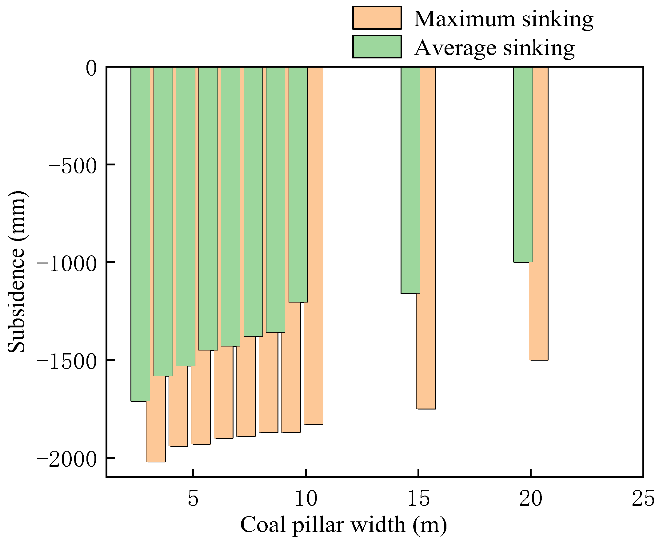
To obtain the deformation characteristics of adjoining rock of NCP, two rows of displacement measuring lines were arranged at the roof of the NCP model and 5 m above it, and 10 displacement measuring points were set in each row. The vertical offset of the roof on the adjoining rock is displayed in Figure 9. The deformation of the adjoining rock varied with the NCP widths. Therefore, the NCP width was critical for controlling the stress and deformation of adjoining rock.
When the width of the NCP increased, subsidence occurred for the roof plate. The maximum subsidence occurred when the width was 3 m, but the supporting conditions of the roadway were limited. When the width was 4–10 m, the roadway subsidence varied between 1200 and 1600 mm, which was in the controllable range. Even though the width of the NCP was between 15 and 20 m, the NCP was subjected to high vertical stress (Figure 7), and the subsidence of the roof was not salient.

4.4. Deformation Distribution of Narrow Coal Pillars in the Plastic Zone

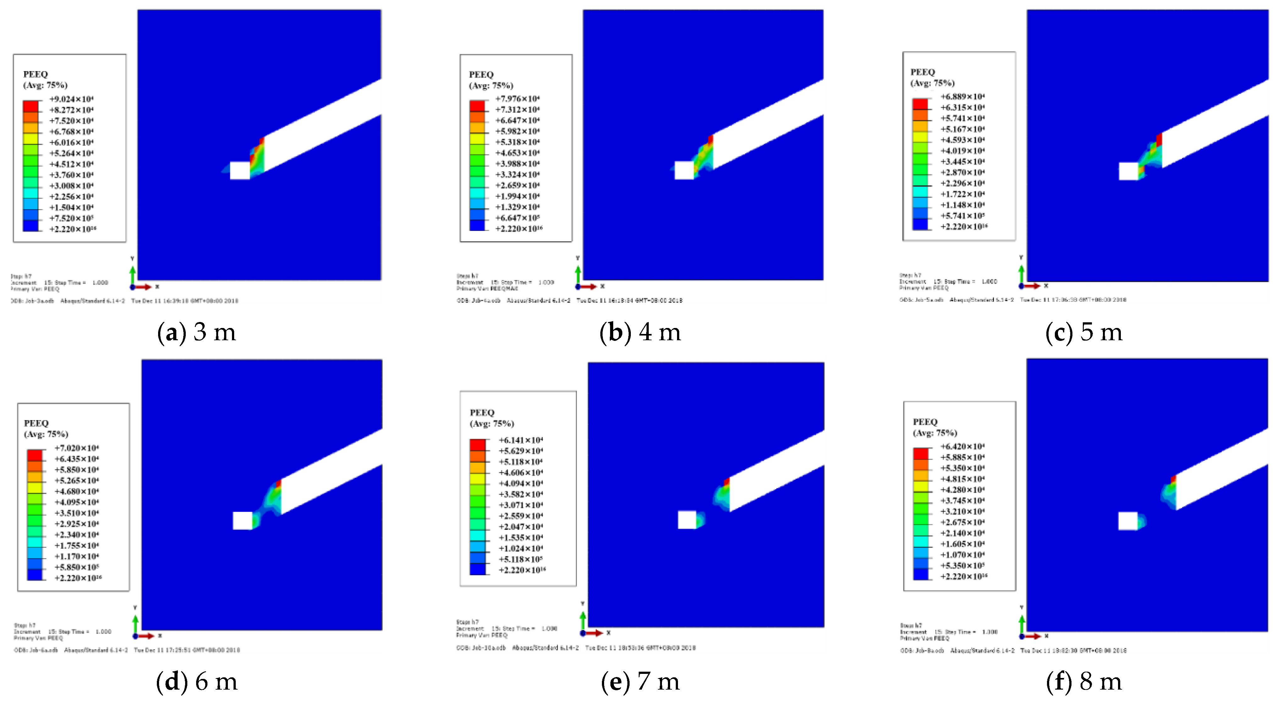
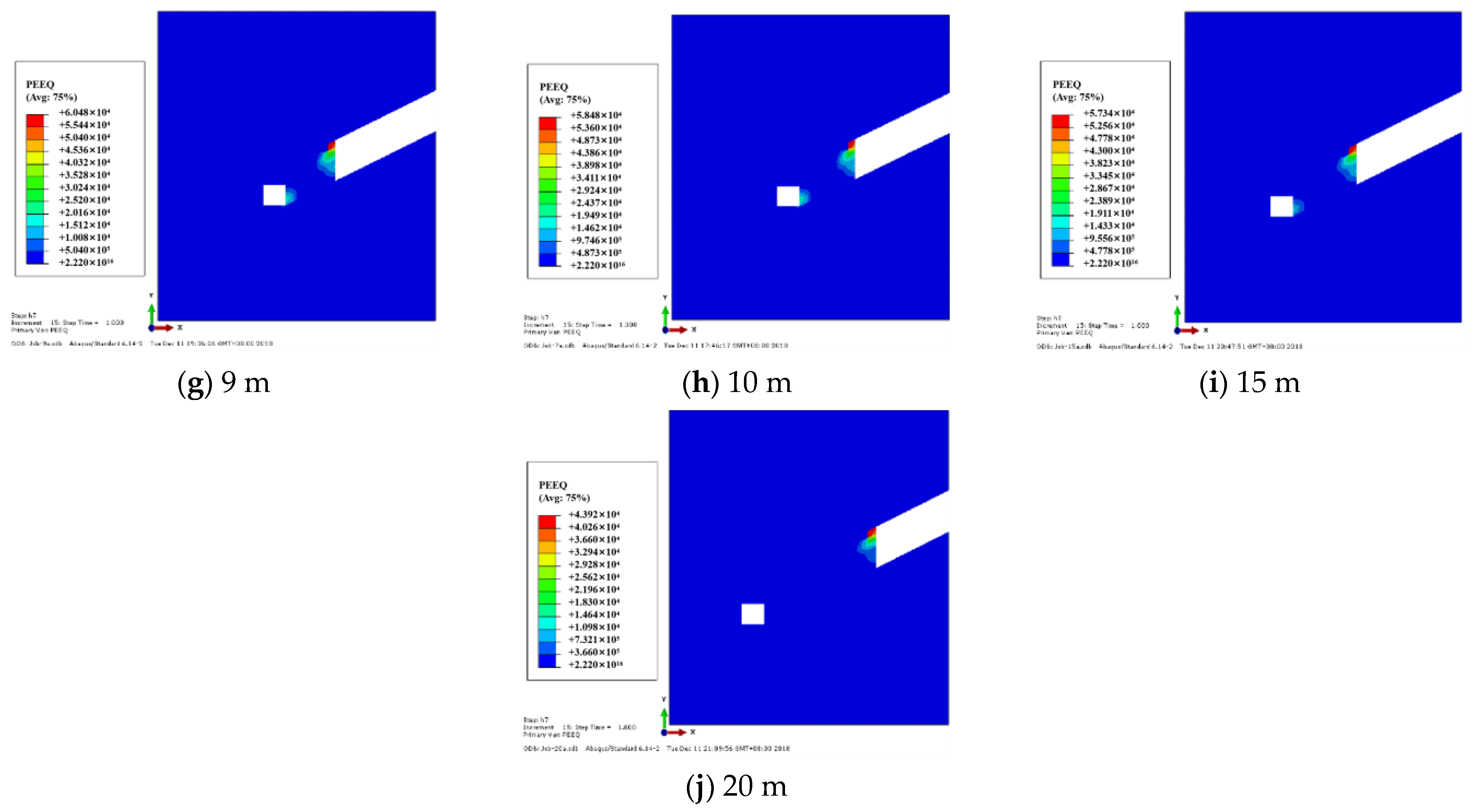
The gob-side tunnel destroyed the lateral stress equilibrium state of the gob, and the NCP was affected by the vertical stress and horizontal stress of the upper strata and the key rock block B (Figure 4). The stress-focused area was formed at the shoulder angle of the roadway, which made the coal pillars easy to break. In the inclined thick coal seam, the plastic zone in the NCP increased with its width, and under the combined action of shear and tensile, it was continuously distributed from the inclination to both sides of the NCP. Therefore, it was necessary to accurately grasp the failure scope and distribution characteristics of the coal pillar’s plastic zone so as to provide a foundation for the selection of critical parameters of roadway support.
Through the numerical calculation of stress distribution characteristics in NCP and adjoining rock during gob-side tunnel driving, the distribution characteristics of the plastic zone in NCP with various widths were obtained, as demonstrated in Figure 10. The graph showed that when the NCP width was 3 m, the upper end of the NCP was seriously damaged. The plastic zone formed by the NCP near the upper end of the gob and the shoulder angle of the roadway runs through the whole NCP, which made the NCP have no stable bearing area. When the NCP width was 4 m, the stress of the plastic zone tended to transfer to the bottom plate, which reduced the stress of adjoining rock and the deformation of NCP. When the NCP width was 5 m, the plastic zone near the gob expanded, indicating that the stress intensity of coal pillars increased. When the NCP width was 6 m, due to the gradual decrease of the plastic zone in the center of the NCP, the stress of the NCP transferred to the two sides, and the roadway support pressure was increased. When the NCP width was 7 m, the plastic zone appeared completely discontinuous area, and the two sides were still dominated by shear failure. When the NCP width was 8–20 m, with the width increased, the range of plastic zone near the NCP side of the roadway shoulder angle gradually shifted to the lower end of the roadway, and the stress transferred to the roof and floor roadway. The deformation of the adjoining rock was mainly a shear and tensile failure, and the adjoining rock was in a high-stress state.
Therefore, considering the resource recovery rate and roadway support pressure, the NCP width of 4 m was the most reasonable.

5. Coal Pillars Stress and Deformation Analysis

5.1. Vertical Stress of the Coal Pillars for Various Widths

The NCP width had an evident effect on the variation law of NCP vertical stress. To analyze the association between the NCP widths and the variation of NCP vertical stress, the variation association between the peak value of vertical stress and the size of NCP was plotted in Figure 11.
The interrelation between the peak value of NCP vertical stress and the widths in Figure 11 was fitted to obtain the relationship shown in Equation (6), and the fitting degree R2 was 0.986. The peak vertical stress increased when the width increased. Apparently, the increase in the width was not favorable for roadway support during mining activities. According to the previous analysis, 3 m NCP had no load-carrying capacity. When the NCP width was greater than or equal to 3 m, its bearing capacity was unknown. Thus, the optimal economic width was 4 m.
σ v = 26.524 24.99 1 + e x i 1.64 1.34
where σv denotes the vertical peak stress of the NCP, xi expresses the width of various NCPs (3, 4, 5, 6, 7, 8, 9, 10, 15, and 20 m).

5.2. Horizontal Stress of Coal Pillars for Varying Widths

The horizontal stress of the NCP for various NCP widths was calculated from previous numerical analysis. The horizontal stress distribution for various NCP widths is displayed in Figure 12.
The interrelation between the mean horizontal stress and the widths in Figure 12 was fitted to obtain the connection shown in Equation (7), and the fitting degree R2 was 0.971. The equation revealed that the horizontal stress increased logarithmically when the width increased. As mentioned, a 3 m wide NCP was the starting point and basic design for analysis. Thus, 3-m width can not be selected as the optimal width. As depicted in Figure 10, when the NCP width was 4 m, the mean horizontal stress was the least, and the force had a limited effect on the NCP during mining activities. Therefore, the 4-m wide NCP was selected to evaluate if it was a suitable option for the support of roadway mining by using the following expression:
σ H = 1.131 ln ( 12.2884 ln x i )
where σH is the horizontal peak stress of the NCP; xi is the width of different NCPs (3, 4, 5, 6, 7, 8, 9, 10, 15, and 20 m).

6. Case Study

6.1. Determining the Width of the Narrow Coal Pillars

Figure 11 and Figure 12 indicate that 4 m NCP width is the ideal width because the mean vertical stress and horizontal stress are minima. Furthermore, when the width was 4 m, its distribution range of the plastic zone and its overall stability exhibited superior properties to that of other widths. Therefore, a 4 m NCP width was selected to design the gob-side tunnel in the (4–5) 06 work face of the Liuhuanggou coal mine in Xinjiang province.

6.2. Anchor Rod and Cable Stress Monitoring

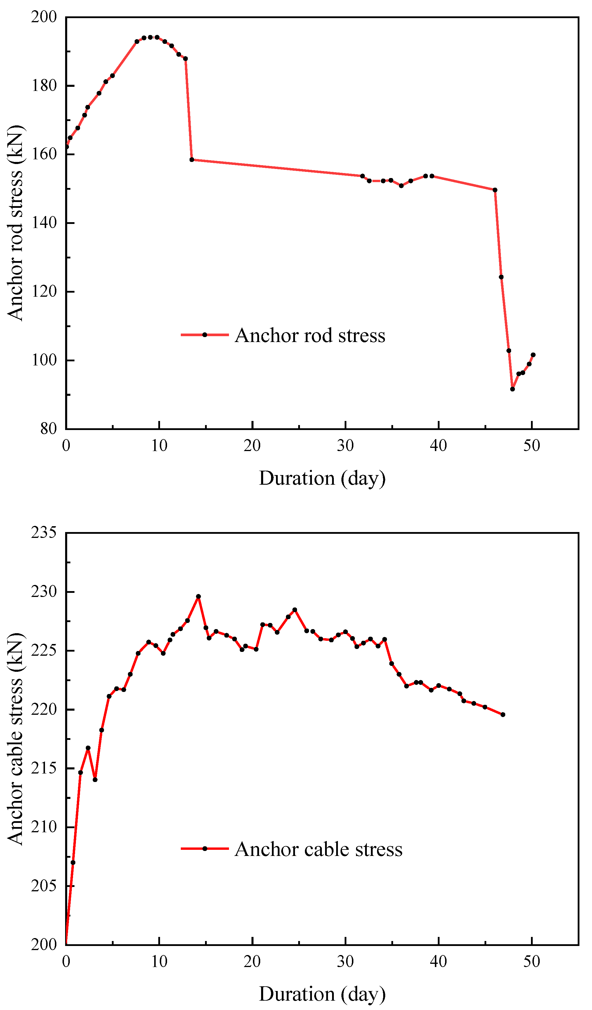
The monitoring of the anchoring force of the anchor rod and cable is shown in Figure 13. Due to the low bearing capacity of the NCP, the anchor rod of the solid coal side and the roof anchor cable were generally subjected to high stress. The pressure of the overlying strata was mainly borne by the solid coal side. The load of the anchor rod varied between 110–200 kN, and the load of the anchor cable varied between 200–230 kN. The specific parameters of the KMG 500 anchor rod of the solid coal side are shown in Table 2. When the anchor rod with a diameter of 20 mm was used, some of the anchor rods were broken, while the anchor cable with a diameter of 22 mm and a strength level of 1860 had an ultimate load of 448.6 kN and still possessed a large bearing space.
In summary, the anchor rod and cable of the roof and both sides in the gob-side tunnel born greater pressure, and some of the anchor rods at the solid coal side corner were broken, while the anchor cable still had a large bearing space. In the geological structure and watering section, the adjoining rock of the roadway was seriously deformed, and it was necessary to strengthen the support in this section and improve the bearing performance of the corner anchorage.

6.3. Observation

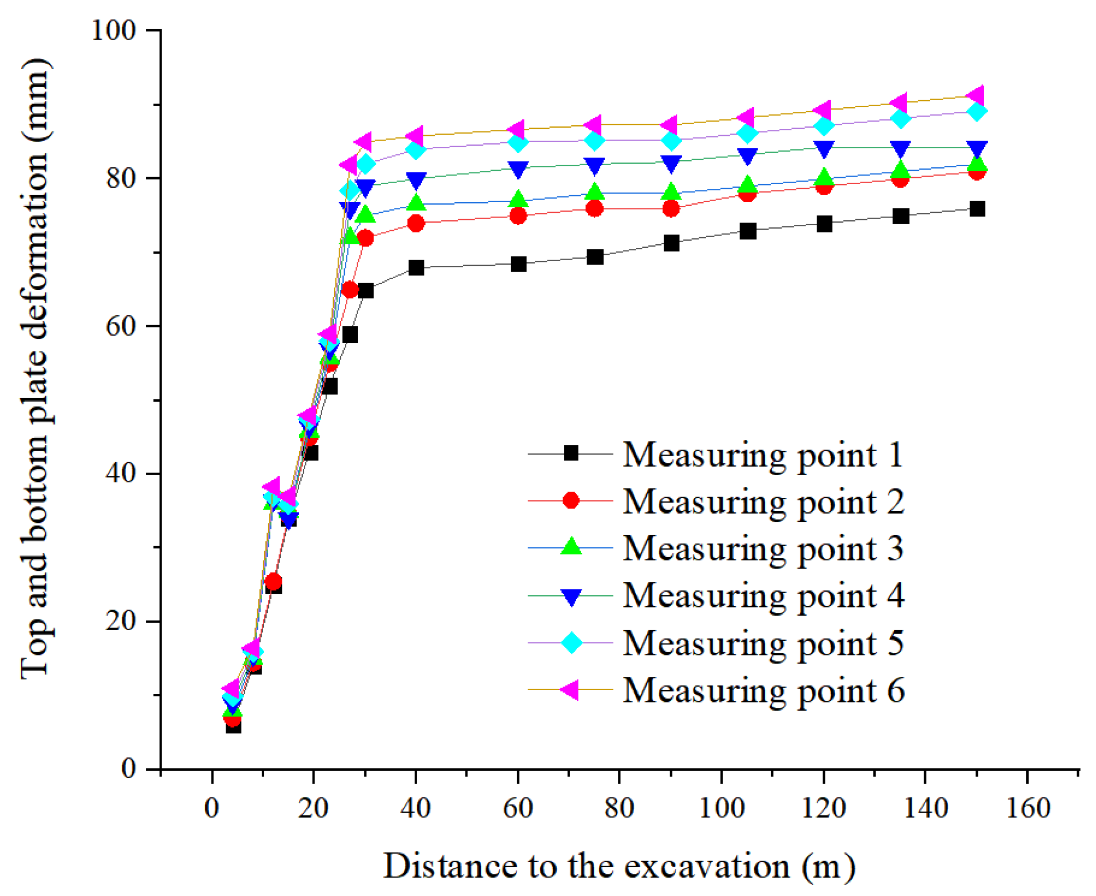
The deformation and stress distribution of the adjoining rock with the NCP on the (4–5) 06 work face were measured on-site. The cross-point method was used to construct a hole 28 mm in diameter and 400 mm in length along the vertical direction of the roof and floor as well as the horizontal direction of both sides. The wooden piles 29 mm in diameter and 400 mm in length were inserted into the hole. The curved measuring nails were installed at the roof, and the flat head measuring nails were installed at the floor. The arrangement of measuring points is listed in Table 3. The time-varying deformation of the roof and two-side are recorded, as demonstrated in Figure 14 and Figure 15.
As demonstrated in Figure 14 and Figure 15, when the NCP width was 4 m, during roadway excavation, the maximum subsidence of the roadway roof was 85 mm, and the maximum displacement on both sides of the roadway was 105 mm. During the stable period of roadway, the roof subsidence and the two-side displacement increased slightly. The maximum roof subsidence was 91.3 mm, and the maximum two-side displacement was 112.3 mm. After that, the roof subsidence and the two-side displacement remained basically unchanged, indicating that 4 m pillars of roadway protection could meet the requirements of the gob-side tunnel in an inclined coal seam.

7. Conclusions

The three primary conclusions of this study are made as below:
  • In the NCP of an inclined coal seam, the vertical stress increases first and then decreases, and the horizontal stress decreases first and then increases from bottom to top. With the rising of the NCP width, the peak values of vertical stress and horizontal stress increase in logarithmic function form. The quantitative relationship between pillar size and peak stress is obtained by fitting.
  • Through the numerical simulation method, the relationship between the NCP width in an inclined coal seam and the stress distribution, the plastic zone distribution, and the peak stress are calculated, respectively. Combined with the measured values of the deformation and stress distribution of the adjoining rock, the optimal dimension mathematical model of the NCP is verified. Therefore, the optimal width of the NCP in the (4–5) 06 fully mechanized caving face is 4 m.
  • The NCP of an inclined coal seam is in the form of oblique cutting failure, and it is necessary to strengthen the support of the roadway shoulder corner. The anchor rod and cable support system designed according to the theoretical and numerical calculation results can provide higher support strength and stiffness, which can effectively control the NCP from slipping to the inside of the roadway, prevent the serious deformation of NCP, meet the support requirements of adjoining rock of gob-side tunnel in (4–5) 06 working face, and ensure the overall stability of the roadway.

Author Contributions

Conceptualization, P.Z.; methodology, S.L.; data curation, W.Z. and Z.C.; writing—original draft preparation, W.Z.; investigation, Y.L. and C.C.; writing—review and editing, Y.S.; resources, Y.J. and F.L.; funding acquisition, Z.W. and J.L. All authors have read and agreed to the published version of the manuscript.

Funding

This research was funded by National Natural Science Foundation Grants of China (51974237, 51704228), the Basic Research on National Natural Science Foundation key project of China (51734007), and the Innovation guidance project of Chongqing Research Institute, China Coal Technology and Engineering Group in 2019 (2019YBXM46).

Institutional Review Board Statement

Not applicable.

Informed Consent Statement

Not applicable.

Data Availability Statement

Data are available on request due to privacy restrictions.

Conflicts of Interest

The authors declare no conflict of interest.

References

  1. Yuan, L. Research progress of mining response and disaster prevention and control in deep coal mine. J. China Coal Soc. 2021, 46, 716–725. (In Chinese) [Google Scholar]
  2. Xie, H.P.; Wang, J.H.; Wang, G.F.; Ren, H.W.; Liu, J.Z.; Ge, S.R.; Zhou, H.W.; Wu, G.; Ren, S. New ideas of coal revolution and layout of coal science and technology development. J. China Coal Soc. 2018, 43, 1187–1197. (In Chinese) [Google Scholar]
  3. Wang, J.; Jiang, J.Q.; Li, G.B.; Hu, H. Exploration and numerical analysis of failure characteristic of coal pillar under great mining height longwall influence. Geotech. Geol. Eng. 2016, 34, 689–702. [Google Scholar] [CrossRef]
  4. Liu, S.F.; Wan, Z.J.; Zhang, Y.; Lu, S.F.; Ta, X.P.; Wu, Z.P. Research on evaluation and control technology of coal pillar stability based on the fracture digitization method. Measurement 2020, 158, 107713. [Google Scholar] [CrossRef]
  5. Dai, J.J.; Shan, P.F.; Zhou, Q. Study on intelligent identification method of coal pillar stability in fully mechanized caving face of thick coal seam. Energies 2020, 13, 305. [Google Scholar] [CrossRef] [Green Version]
  6. Wu, H.; Wang, X.K.; Wang, W.J.; Peng, G.; Zhang, Z.Z. Deformation characteristics and mechanism of deep subsize coal pillar of the tilted stratum. Energy Sci. Eng. 2020, 8, 544–561. [Google Scholar] [CrossRef]
  7. Qi, J.D.; Chai, J.; Zhang, J.Z. Numerical simulation on stress distribution of the inclined coal seam under different pillar width. Adv. Mater. Res. 2014, 977, 374–377. [Google Scholar] [CrossRef]
  8. Jaiswal, A.; Shrivastva, B.K. Numerical simulation of coal pillar strength. Int. J. Rock Mech. Min. Sci. 2008, 46, 779–788. [Google Scholar] [CrossRef]
  9. Zhang, Z.Z.; Deng, M.; Wang, X.Y.; Yu, W.J.; Zhang, F.; Dao, V.D. Field and numerical investigations on the lower coal seam entry failure analysis under the remnant pillar. Eng. Fail. Anal. 2020, 115, 104638. [Google Scholar] [CrossRef]
  10. Wu, H.; Zhang, N.; Wang, W.J.; Zhao, Y.; Cao, P. Characteristics of deformation and stress distribution of small coal pillars under leading abutment pressure. Int. J. Min. Sci. Technol. 2015, 25, 921–926. [Google Scholar] [CrossRef]
  11. Wang, B.N.; Dang, F.N.; Gu, S.C.; Huang, R.B.; Miao, Y.P.; Chao, W. Method for determining the width of protective coal pillar in the pre-driven longwall recovery room considering main roof failure form. Int. J. Rock. Mech. Min. Sci. 2020, 130, 104340. [Google Scholar] [CrossRef]
  12. Yang, R.S.; Zhu, Y.; Li, Y.L.; Li, W.Y.; Lin, H. Coal pillar size design and surrounding rock control techniques in deep longwall entry. Arabian J. Geosci. 2020, 13, 453. [Google Scholar] [CrossRef]
  13. Bai, J.-B.; Shen, W.-L.; Guo, G.-L.; Wang, X.-Y.; Yu, Y. Roof deformation, failure characteristics, and preventive techniques of gob-side entry driving heading adjacent to the advancing working face. Rock Mech. Rock Eng. 2015, 48, 2447–2458. [Google Scholar] [CrossRef]
  14. Qi, F.Z.; Ma, Z.G.; Yang, D.W.; Li, N.; Li, B.; Wang, Z.L.; Ma, W.X. Stability control mechanism of high-stress roadway surrounding rock by roof fracturing and rock mass filling. Adv. Civil Eng. 2021, 2021, 317–334. [Google Scholar] [CrossRef]
  15. Zhao, Y.-M.; Feng, X.-T.; Jiang, Q.; Han, Y.; Zhou, Y.-Y.; Guo, H.-G.; Kou, Y.-Y.; Shi, Y.-E. Large deformation control of deep roadways in fractured hard rock based on cracking-restraint method. Rock Mech. Rock Eng. 2021, 54, 2559–2580. [Google Scholar] [CrossRef]
  16. Wu, X.-Y.; Jiang, L.-S.; Xu, X.-G.; Guo, T.; Zhang, P.-P.; Huang, W.-P. Numerical analysis of deformation and failure characteristics of deep roadway surrounding rock under static-dynamic coupling stress. J. Cent. South Univ. 2021, 28, 543–555. [Google Scholar] [CrossRef]
  17. Li, Z.L.; Wang, L.G.; Lu, Y.L.; Li, W.S.; Wang, K. Effect of principal stress rotation on the stability of a roadway constructed in half-coal-rock stratum and its control technology. Arabian J. Geosci. 2021, 14, 292–303. [Google Scholar] [CrossRef]
  18. Xu, B.; Li, Y.; Wang, S.; Lu, B. Study on the strength characteristics and failure characteristics of the composite load-bearing structure in the cemented filling field. Constr. Build. Mater. 2022, 330, 127242. [Google Scholar] [CrossRef]
  19. Ji, S.T.; Karlovšek, J. Calibration and uniqueness analysis of microparameters for DEM cohesive granular material. Int. J. Min. Sci. Technol. 2022, 32, 121–136. [Google Scholar] [CrossRef]
  20. Ji, S.T.; Karlovšek, J. Optimized differential evolution algorithm for solving DEM material calibration problem. Eng. Comput. 2022, 1–16. [Google Scholar] [CrossRef]
  21. Zhu, X.J.; Guo, G.L.; Liu, H.; Peng, X.; Yang, X.Y. Stability analysis of the composite support pillar in backfill-strip mining using particle flow simulation method. Environ. Earth Sci. 2022, 81, 124. [Google Scholar] [CrossRef]
  22. Fu, J.W.; Haeri, H.; Sarfarazi, V.; Babanouri, N.; Rezaei, A.; Manesh, M.O.; Bahrami, R.; Marji, M.F. Effects of axial loading width and immediate roof thickness on the failure mechanism of a notched roof in room and pillar mining: Experimental test and numerical simulation. Rock Mech. Rock Eng. 2022, 1–27. [Google Scholar] [CrossRef]
  23. Sarfarazi, V.; Abharian, S.; Ghorbani, A. Physical test and PFC modelling of rock pillar failure containing two neighboring joints and one hole. Smart Struct. Syst. 2021, 27, 123–137. [Google Scholar]
  24. Fan, N.; Wang, J.R.; Zhang, B. Reasonable width of segment pillar of fully-mechanized caving face in inclined extra-thick coal seam. Geotech. Geol. Eng. 2020, 38, 4189–4200. [Google Scholar] [CrossRef]
  25. Wang, Q.; Gao, H.K.; Jiang, B.; Li, S.; He, M.; Wang, D.; Lu, W.; Qin, Q.; Gao, S.; Yu, H.C. Research on reasonable coal pillar width of roadway driven along goaf in deep mine. Arabian J. Geosci. 2017, 10, 466–483. [Google Scholar] [CrossRef]
  26. Fan, L.; Wang, W.J.; Yuan, C.; Peng, W.Q. Research on large deformation mechanism of deep roadway with dynamic pressure. Energy Sci. Eng. 2020, 8, 3348–3364. [Google Scholar] [CrossRef]
  27. Zhang, Y.; Wan, Z.J.; Li, F.C.; Zhou, C.B.; Zhang, B.; Feng, G.; Chengtan, Z. Stability of coal pillar in gob-side entry driving under unstable overlying strata and its coupling support control technique. Int. J. Min. Sci. Technol. 2013, 23, 193–199. [Google Scholar] [CrossRef]
  28. Wojciechowski, W. A note on the differences between Drucker-Prager and Mohr-Coulomb shear strength criteria. Stud. Geotech. Mech. 2018, 40, 163–169. [Google Scholar] [CrossRef] [Green Version]
  29. Loboda, V.; Gerge, I.; Khodanen, T.; Mykhail, O. A crack between orthotropic materials with a shear yield zone at the crack tip. Math. Prob. Eng. 2019, 2019, 9723089. [Google Scholar] [CrossRef]
  30. Zhang, K.X.; Jiang, Y.D.; Zhang, Z.B. Determination of reasonable width of narrow coal pillars along goaf in large coal pillars. J. Min. Saf. Eng. 2014, 31, 255–262. (In Chinese) [Google Scholar]
Figure 1. (4–5) 06 working face layout diagram.
Sustainability 14 16014 g001
Figure 2. Schematic of the spatial position of the gob-side tunnel.
Sustainability 14 16014 g002
Figure 3. The RMT–150C rock mechanics test.
Sustainability 14 16014 g003
Figure 4. Schematic of the rock structure adjoining the NCP.
Sustainability 14 16014 g004
Figure 5. Three-dimensional numerical model.
Sustainability 14 16014 g005
Figure 6. Vertical stress distribution of the NCP of various sizes.
Sustainability 14 16014 g006aSustainability 14 16014 g006b
Figure 7. Vertical stress distribution curves of the NCP of various widths.
Sustainability 14 16014 g007
Figure 8. Horizontal stress distribution curves with the NCP widths of 3, 4, 5, 6, 7, 8, 9, 10, 15, and 20 m.
Sustainability 14 16014 g008
Figure 9. Vertical displacement of the roof of the adjoining rock with respect to the coal pillar width.
Sustainability 14 16014 g009
Figure 10. Cloud distribution of the plastic zone with the NCP widths of 3, 4, 5, 6, 7, 8, 9, 10, 15, and 20 m.
Sustainability 14 16014 g010aSustainability 14 16014 g010b
Figure 11. Vertical stress peak change versus the NCP width.
Sustainability 14 16014 g011
Figure 12. Horizontal stress distribution with the NCP widths of 3, 4, 5, 6, 7, 8, 9, 10, 15, and 20 m.
Sustainability 14 16014 g012
Figure 13. Anchor rod and cable stress monitoring of rock surrounding the roadway versus duration.
Sustainability 14 16014 g013
Figure 14. Deformation curves for six measuring points.
Sustainability 14 16014 g014
Figure 15. Top and bottom plate deformation curve for six measuring points.
Sustainability 14 16014 g015
Table 1. 4–5# Roof and floor rock parameters.
PositionLithologyγ
(kN/m3)
E
(MPa)
Poisson
(p)
C0
(MPa)
Dilatancy Angle (°)Internal Friction Angle (°)Tensile Strength
(MPa)
RoofMudstone20.820,0190.190.938310.67
Middle sandstone26.650,4300.282.2710310.85
Fine sandstone26.243,0200.261.9310310.56
Siltstone20.034,7390.251.312350.87
Coal seamCoal14.614,1420.270.728200.53
Bottom plateCoarse sandstone26.456,7670.271.388340.34
Sandy mudstone26.456,7670.271.388340.34
Table 2. Selected parameters for anchors and anchor cables.
SelectionTypeDistance between Anchors (mm)Diameter (mm)Length (mm)Resin Roll Anchoring
AnchorsKMG500800222200MSCK2370
Anchor cablesKMG8001600227300MSCK2335
Table 3. Measuring point design.
Measuring Point123456
Distance from heading face (m)20040060080010001200
Publisher’s Note: MDPI stays neutral with regard to jurisdictional claims in published maps and institutional affiliations.