Abstract
In Indonesia, the adoption of the underground coal mining method is discussed to extend coal production. However, the geological conditions in Indonesia are very weak. In particular, the mechanical properties of the immediate roof/floor in shallow depths are weaker than those of coal. Therefore, the control measures to maintain stability around the developing area should be discussed for safe longwall mining operations. This study discusses the design of safety pillar width in longwall mining under weak geological conditions by using FLAC3D. The study reveals that the conventional equations for the determination of the pillar width, i.e., Obert-Duvall, Holland-Gaddy, and Bieniawski equations, can be adopted to maintain the stability of the pillar itself but are not suitable for the stability of the longwall face because of the influence of the extracted neighboring panels. Additionally, the increase of the pillar width can significantly reduce the fracture zone around the longwall face. Also, increasing the setting load of the powered support can slightly improve the stability. In the pillar design, both the pillar strength and the stability of the longwall face under weak geological conditions need to be considered.
1. Introduction
Indonesia is one of the world’s leading coal-producing countries. Most of the coal is produced by surface mining. Coal production in Indonesia was approximately 275 million tons in 2010, 461 million tons in 2015, and 613 million tons in 2021, with production increasing each year. Demand for coal in Indonesia is also increasing. The energy mix of Indonesia for coal is projected to increase by 10% of the country’s total energy mix from 2011 to 2025 [1]. However, factors such as increasing stripping ratio, protected areas, urban structures/urban infrastructural developments, and agricultural activities will limit the amount of coal that can be extracted. The transition of mining from surface mining to underground mining is being considered to extend/enhance coal production. Longwall mining is a typical underground coal mining method with a high production rate. However, the guidelines for a longwall mining operation in other countries with major coal mining operations are not applicable to Indonesia. This is mainly because, comparatively, the geotechnical conditions of coal and the surrounding strata in Indonesia are much poorer. Therefore, it is necessary to conduct research on stability control of underground longwall mining under weak geological conditions in Indonesia. Brady and Brown indicate that the main measures of longwall mining methods are classified into four categories: longwall face stability control, stability of the main roadway and gate entry, stability of the chain or rib pillar, and backfilling at the goaf area [2]. The pillar is important for protecting the unmined panel from the influence of mined panel though excessive pillar design causes decreases in recovery rate. Therefore, various studies have been conducted on pillar design. Hsiung and Peng conducted a three-dimensional stress analysis of a pillar design for a coal mine in the U.S. As a result, they proposed a chart diagram that could determine the appropriate pillar width based on several factors, including the uniaxial compressive strength of coal, panel length, and panel width [3]. Sinha and Walton used borehole pressure cell (BPC) data obtained from mines in the western United States to better assess the process of stress redistribution in the coal mine during mining [4]. Klemetti et al. studied the extent and magnitude of the abutment loading experienced due to the extraction of the longwall panels in a coal mine. The result of the numerical analysis showed that the increase in load during longwall panel extraction was negligible [5]. Yang et al. studied pillar design by combining numerical simulation and field test results from the Zhaozhuang coal mine located in Changzhi City, Shanxi Province, China. The results indicated that the peak stress moves to the pillar side as the pillar width increases. The study also noted that peak stress is greatly affected by coal extraction near the goaf [6]. Based on numerical analysis and field data, Qian et al. studied the appropriate pillar design for stabilizing goaf-side entry driving in the Guqiao Coal Mine, China. As a result, they found that the support schemes, if introduced at the goaf-side entry driving, could effectively suppress the deformation of the surrounding rock mass [7]. Moreover, Ghosh et al. conducted an analysis of chain pillars in multi-seam longwall mining panels in coal mines in India [8]. However, these studies were conducted on coal mines with relatively high-strength geotechnical conditions. In a study on longwall mining under weak geological conditions, Yu et al. monitored the Tashan coal mine in Shanxi, China, to evaluate the performance of coal pillars under a weak roof that had been degraded by igneous rock intrusions [9]. Xu et al. used numerical simulations to determine pillar stress in a coal mine with weak and tilted conditions [10]. Indonesian strata are composed of sandstone, clay, shale, and other sediments typically found in deltaic and shallow-water depositional environments. The rock strengths measured in these strata are much lower than the rock strengths of most coal mines in the world [11]. In the past, coal mining using the longwall mining method was conducted in the Ombilin, Fajar Bumi Sakti, and Kitadin Embalut coal mines. All of these mines have since closed due to accidents related to ground stability [12,13]. Several studies have been conducted on the stability of longwall face and gate entry in the coal mines studied in this research [14,15]. Putri conducted a study on appropriate pillar strength equations based on data from the Air Laya coal mine in Indonesia. The study stated that the Bieniawski equation and Obert-Duvall equation were appropriate [16]. However, not only the pillar stability but also the influence on the longwall coal face should be considered in Indonesia because the strength of the surrounding rock is weaker than the strength of the coal seam in shallow depths. Therefore, it is necessary to investigate the influence of the pillar design on the stability of the pillar and the longwall face. The purpose of this study is to investigate the effect of the weak immediate roof and floor strata on pillar and longwall face stability by numerical analysis using FLAC3D. The main objective is to obtain design guidelines for pillars under poor geological conditions in Indonesia.
2. Numerical Model
2.1. Global Model Description
The coal mine under study is located in the Kutai basin of East Kalimantan province. The coal seam in the study area is a monocline structure with a maximum dip of 13°. The mining area is composed of a series of parallel panels consisting of one working face, two entries, and one pillar between the panels. Panel sizes range from 130 m to 150 m in width and 500 m to 1000 m in length. The gate entry is 3 m wide by 5 m high, and the roof is supported at 1 m spacing by steel arches with a maximum yield strength of 540 MPa. A numerical model was created in FLAC3D based on actual field conditions. Figure 1 shows the numerical model used in this study. The model consists of panels 1 and 2 and a pillar between those panels. A half-section model is created for the enclosed area by the red dotted line. The overburden depth is 100 m. The thickness of the coal seam is 3 m. The dimensions of one panel are 150 m for the panel width and 200 m for the panel length. For our half-section model, the size of the panel width is 75 m, half of the 150 m. The pillar widths are 3 m, 5 m, 7 m, 10 m, 15 m, 20 m, and 30 m to examine how different pillar widths affect pillar stability and longwall face stability. When studying the progressive failure of a rock mass using a numerical model, it is necessary to estimate the post-failure characteristics of the rock mass. Hoek and Brown divided rock mass into three categories: very good-quality rock mass, average-quality rock mass, and very poor-quality rock mass. They described the general mechanical properties and post-failure. The elastoplastic model is suitable when the rock mass is weak. This is appropriate for the coal mine in this study, where the rock mass is classified as a very poor-quality rock mass [17]. Therefore, an elastoplastic model with the Mohr-Coulomb failure criterion is adopted in this study. The narrow mesh size is adopted around the coal seam. The mesh becomes wider away from the coal seam to reduce the computational volume. The mesh size in the area near the coal seam is 0.25 m × 0.25 m × 0.25 m. The stress ratio is 1.0. The boundary conditions are as follows: the surface is free, the bottom is fixed in the vertical direction, and the side plane is locked in the horizontal direction. Table 1 shows the input properties of the model, where Claystone is the immediate roof/floor rock of the coal mine in this study. These properties were obtained from the laboratory results of core samples from the actual site.
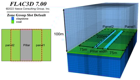
Figure 1.
Overview of numerical model.

Table 1.
Mechanical properties of rock.
2.2. Modeling of Goaf
One method of modeling the goaf is to replace both the excavated panel and the caved zone above it with a softer material after the panel has been excavated. The goaf is modeled by assigning the properties of the goaf, as shown in Figure 2. The height of the caved zone can be estimated by using Equation (1) [18,19].
where is the height of caved zone (m), is mining height (m), and , are strata lithology coefficients. In this coal mine, the mining height is 3 m, and the uniaxial compressive strength of the claystone is 4.84 MPa. According to Table 2, the immediate roof/floor rock is classified as weak, meaning that the values of and are respectively 6.2 and 32. Based on these values, the height of the caved zone is calculated to be 5.93 m.
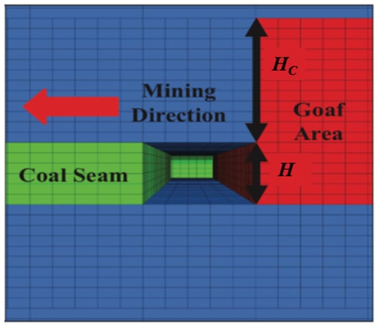
Figure 2.
Model of the goaf.
Table 2.
Rock mass classification and values of and .
2.3. Modeling of Steel Arch and Powered Support
The steel arch of the gate entry and the powered support of the longwall face is modeled using beam elements. Table 3 shows the properties of the steel arch and powered support, and Figure 3 shows the overview of the model. The setting load of the powered support is modeled by applying a load to the top and bottom of the longwall face. Based on the standards for the powered support used in the coal mine under study, the setting load is varied to 6000 kN, 8000 kN, and 10,000 kN [14]. The floor of the longwall face is applied with a load that considers these setting loads and the weight of the powered support.
Table 3.
Material properties of steel arch and powered support.
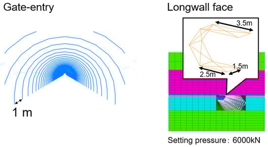
Figure 3.
Model overview of steel arch and powered support.
2.4. Model Validation
Model validation is an important step in the numerical study to assess the validity of the modeling in representing the/actual field conditions. Trial panels have been mined in the Kutai basin of East Kalimantan province, which is the second-largest coalfield in Indonesia. However, sufficient data on the panel extraction stage could not be obtained because mining was difficult due to the poor geological condition in Indonesia. Therefore, the model was validated by comparing the displacement of gate entry during the gate entry excavation stage. The overburden depth and coal thickness of the trial panel are the same as those in the analytical model. During gate entry excavation, the displacement of the roof was measured by using a telltale (strata extensometer). To discuss the validity of the model, the analysis results are compared with the in-situ displacement data of the roof set in the center of the gate entry. Figure 4 shows the results of the comparison between the analytical results and the in-situ monitoring data. The horizontal axis shows the number of days since the gate entry is excavated and the number of calculation steps. The vertical axis shows the roof displacement of the gate entry. The green line in the figure shows the field data, and the blue line shows the analysis results. The in-situ monitoring data show the relationship between the number of days since the gate entry is excavated and the roof displacement. On the other hand, the analytical results show the relationship between the simulation step and the roof displacement. The horizontal axis is different for the results of in-situ monitoring data and the analysis results. There is no method to convert this simulation step to an actual time for comparison. Therefore, some deviations are observed from those curves. However, the simulation results are intended to illustrate the state of the model at equilibrium. The roof displacement in the field is also approximately constant at equilibrium. The roof displacement is 7 mm in the field data and 6.6 mm in the analytical results, which are approximately the same values, comparing the results after 7 October 2019, when the stresses are considered to have converged. Therefore, it can be concluded that the validation of the numerical model is confirmed.
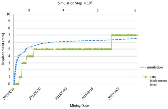
Figure 4.
Comparison of field data and analysis results.
3. Result and Discussion
The coal pillar has an important role to minimize the influence of previous panel extraction. Therefore, the pillar design must consider the stability of the pillar itself and the influence of the neighboring panel extraction on the stability of the longwall face. This study has put into consideration the following factors: pillar stability using the safety factor, the effect of pillar width on the stability of the longwall face, and the influence of the strength of the immediate roof/floor rock on the stability around the pillar.
3.1. Pillar Design Based on Safety Factor
The safety factor is a critical guideline in pillar design. It refers to the ratio of pillar strength to the pillar load. In this study, in order to discuss pillar stability using the factor of safety, the vertical stresses in the pillars were examined. It is known from previous studies that the stress is highest near the center of the panel when the panel is fully excavated. It is also known that the stress in the pillars increases near the longwall face during panel extraction [3]. Therefore, this study focused on the stress distribution in the coal seam along the yellow dotted line when panel 2 is excavated up to a distance of 100 m (Figure 5). All of panel 1 is excavated.
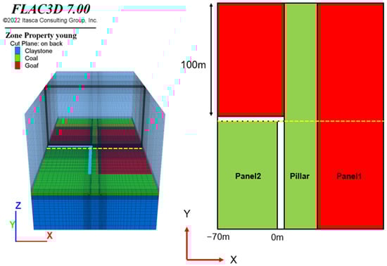
Figure 5.
Mining condition and measurement point.
Figure 6 shows the stress distribution around the pillar at different pillar widths. In this figure, the horizontal axis shows the distance from the gate entry, and the vertical axis shows the vertical stress in the coal seam. Each line shows the results for each pillar width. The peak stress measurement in the pillar near the gate entry was 13.75 MPa for a pillar width of 5 m, 11.46 MPa for a pillar width of 10 m, and 8.05 MPa for a pillar width of 30 m. The stress in the pillar was noted to decrease with increasing pillar width. The stress distribution for the pillar with a width of 3 m differs from that of the other pillar widths. This is attributed to the yielding of the entire pillar. The peak stresses of the panels were as follows: 19.96 MPa for a pillar width of 3 m, 16.22 MPa for a pillar width of 10 m, and 14.50 MPa for a pillar width of 30 m. The stress in the panel also decreased with increasing pillar width. These results suggest that the influence of mined-out panels can be reduced by increasing pillar width.
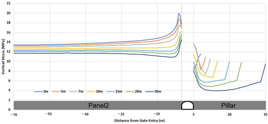
Figure 6.
The stress distribution around the pillar.
The stress distribution of the coal seam along the yellow dotted line in Figure 7 was also investigated. Figure 8 shows the stress distribution in front of the longwall face. In this figure, the horizontal axis shows the distance from the longwall face, and the vertical axis shows the vertical stress. Each line shows the results for each pillar width. At a distance of 5 m from the longwall face, the measurements for the vertical stresses were 12.01 MPa for a 3 m pillar width, 8.19 MPa for a 10 m pillar width, and 5.97 MPa for a 30 m pillar width. At a distance of 45 m from the longwall face, the vertical stress readings indicated 7.62 MPa for a 3 m pillar width, 5.86 MPa for a 10 m pillar width, and 4.34 MPa for a 30 m pillar width. This result indicates that the stresses in the pillar become smaller as the pillar width increases, regardless of the distance from the longwall face. At a distance of 45 m from the longwall face, the difference in vertical stress between the pillar width of 3 m and 30 m is 3.28 MPa, but near the face, the difference in vertical stress between the pillar width of 3 m and 30 m is 8.26 MPa. The difference in the stresses in the pillar width near the mining face was thus noted to be significant. These results suggest that increasing the pillar width is effective in improving the stability of the longwall face near the pillar. The stress peaks near the longwall face indicate that additional support is necessary near the longwall face.
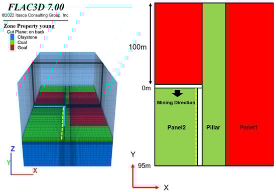
Figure 7.
The Stress measurement point in front of the longwall face.
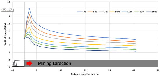
Figure 8.
The Stress measurement point in front of the longwall face.
The safety factor obtained from the pillar strength ratio to the pillar load can be calculated as shown in Equation (2) [3].
where is the safety factor, is UCS of coal (MPa), is stress in the pillar (MPa) and A is the cross-section area of the pillar (m2). The cross-section area of the pillar is the area enclosed by the dotted line shown below in Figure 9.
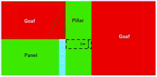
Figure 9.
The cross-section area of the pillar.
It is known that the strength of the pillar increases with the pillar’s width-to-height ratio. In this study, the pillar’s strength is calculated using the following existing three equations since there is no data available on pillar strength equations for coal mines in Indonesia [16].
- Obert-Duvall equation
- Holland-Gaddy equation
- Bieniawski equation
Table 4.
Relationship between pillar width and the safety factor of a pillar.
3.2. Pillar Design Based on the Stability of Longwall Face
One of the main purposes of pillars is to minimize the influence of the previous panel extraction on the gate entry and the longwall face of the unmined panel. This study examined the effects of pillar width and the setting load of the powered support on the stability of the longwall face. In order to investigate the influence of the excavated panel, great consideration was placed on the failure zone. In particular, that of the longwall face near the gate entry when only panel 1 is excavated up to a distance of 100 m and when panel 2 is also excavated to a similar distance of 100 m after the complete extraction of panel 1, as shown in Figure 10.
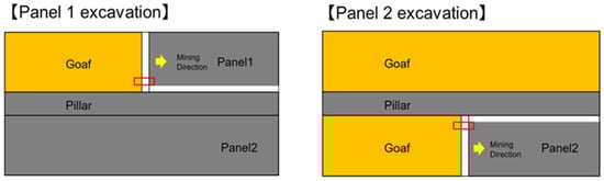
Figure 10.
The failure zone measurement points on the longwall face.
First, the impact of the excavated panels was examined. Figure 11 shows the failure zones around the longwall face in panel 1 excavation and panel 2 excavation. The red areas in the figure indicate areas where shear failure is likely to occur, and the orange areas indicate locations that are most susceptible to both shear and tensile failures. When panel 1 is excavated, the fracture area is approximately the same regardless of the pillar width. This is because the excavation conditions are the same regardless of the pillar width. When panel 2 is excavated, the failure zone around the longwall face increases for all pillar widths. The failure zone extending from the goaf also increased, suggesting that the influence of stress redistribution in the goaf area extended to the roof of the longwall face. These results indicate that the stability of the longwall face is affected by the excavated panel. Therefore, the appropriate pillar design is necessary to reduce the influence of the excavated panels.
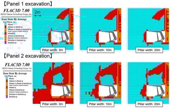
Figure 11.
The effect of the excavated panel on the failure zone around the longwall face.
Figure 12 shows the effects of pillar width and setting load on the failure zone of the longwall face. A comparison of the effect of pillar width on longwall face stability shows that the failure zone decreases as the pillar width increases. In the case of a pillar width of 3 m, the wide range of the longwall face’s roof and floor show the yield condition. In the case of a pillar width of 10 m, the failure zone of the roof is significantly reduced, but the entire floor fails. In the case of the pillar width of 20 m, the failure area decreases in the range where the load is applied by the powered support on both the roof and floor. The failure zone is reduced in the roof and floor when the setting loads increase. When the setting load is 6000 kN in the case of a pillar width of 20 m, the entire floor shows yield condition. On the other hand, when the setting load is 8000 kN or 10,000 kN, the failure zone decreases around the center of the floor. It is observed that the increase in setting load reduces the failure zone at the roof and floor, but the effect is limited compared to the rise in pillar width. This fact means that increasing the pillar width to improve the stability of the face would provide benefits such as a safer workspace and improved movement of the powered supports. The previous section clarified that for stability, a pillar requires more than 10 m of width, especially when the focus is on the pillar strength only. A pillar width of 10 m would result in complete failure. This would inhibit proper movement of the powered support. However, a pillar width of more than 10 m should be discussed if focus is on the stability of the face because there are still large failure zones around the roof and the floor below the support. The effect of the setting load on the stability of the longwall face around the pillar is limited because the failure area around the face almost does not change even when the setting load is increased. On the other hand, when the pillar width increases to 20 m, the failure area significantly decreases regardless of the setting load. The reduction of the failure zone when the pillar width increases is very large compared to the reduction of the failure zone when the setting load increases, indicating that the pillar design has a greater effect on the stability of the longwall face near the pillar than the setting load.
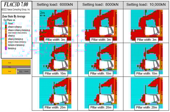
Figure 12.
The effects of pillar width and setting load on the stability of the longwall face.
3.3. Influence of Immediate Roof/Floor Rock Strength on Pillar Design
The previous two studies discussed pillar design under weak geological conditions in Indonesia. This section examined the influence of the strength of the immediate roof/floor rock on the pillar design. The mechanical properties of claystone were assigned as shown in Table 5 [22]. The properties of the claystone 2 of the immediate roof/floor rock were referred from another coal mine. Hoek and Brown classified rock masses into three categories (very good-quality rock mass, average-quality rock mass, and very poor-quality rock mass) and presented the general mechanical properties of each rock mass [17]. Based on this classification, the immediate roof/floor rock having the mechanical properties shown in Table 1 and Table 5 were categorized as very poor-quality rock mass and average-quality rock mass, respectively.
Table 5.
The mechanical properties of the immediate roof/floor rock [22].
Figure 13 shows the failure zone around the longwall face during Panel 2 excavation under the different rock mass strengths. In both cases, the pillar width is 10 m, and the setting load is 6000 kN. The immediate roof/floor of the longwall face failed in 4.84 MPa of the claystone, although the failure zone around the longwall face is limited to 29.2 MPa of the claystone. In the case where the strength of the immediate roof/floor rock is stronger than that of the coal, the longwall face is stable even if the pillar is designed based on the strength of the pillar only. However, under conditions where the strength of the immediate roof/floor rock is weaker than that of the coal, there are notable influences on stability around the longwall face if the pillar is designed to meet the required safety factor based on the strength of the pillar alone. Therefore, it is necessary to consider not only the strength of the pillar but also the stability of the longwall face when designing a pillar, more so when the immediate roof/floor rock is weaker than the strength of the coal.
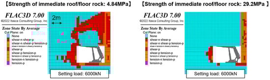
Figure 13.
The effect of immediate roof/floor strength on stability around the longwall face.
4. Conclusions
This study investigated the stability of pillars in underground longwall coal mines under weak geological conditions by using FLAC3D. This study can therefore put forth the following knowledge:
- The stress acting on the pillar is reduced with increasing pillar width. The vertical stress in the pillar showed 13.75 MPa for a 5 m pillar width, 11.46 MPa for a 10 m pillar width, and 8.05 MPa for a 30 m pillar width.
- When the pillar width is 10 m, the safety factors for the pillar, when applying the Obert-Duvall, Holland-Gaddy, and Bieniawski equations, are 1.51, 1.82, and 1.83, respectively. It means that a pillar width of 10 m or more is needed if the required safety factor is in the range of 1.5~2.0.
- The increased pillar width significantly improves the stability of the roof and floor of the panel adjacent to the extracted panel. In the case of a pillar width of 10 m, the failure zone of the roof is reduced dramatically, but the entire floor fails. In the case of the pillar width of 20 m, the failure area decreases in the range where the load was applied by the powered support on both the roof and floor.
- There is a slight stability improvement due to the powered support setting load. The design of the pillar width has a more significant impact on improving the stability of the longwall face.
- Pillar design should consider the influence of the extracted neighboring panels on longwall face stability if the immediate roof/floor rock is weaker than the coal seam.
Author Contributions
H.H. and T.S. conceived the idea of this study. H.H. and P.M. developed the numerical analysis plan and conducted the numerical analysis. U.B. contributed to the interpretation of the results. H.H. and A.H. drafted the original manuscript. H.S. and J.O. supervised the conduct of this study. All authors have read and agreed to the published version of the manuscript.
Funding
JSPS KAKENHI Grant Number JP22K05005.
Institutional Review Board Statement
Not applicable.
Informed Consent Statement
Not applicable.
Data Availability Statement
The data used to support the findings of this study are available from the corresponding author upon request.
Acknowledgments
The authors also express sincere thanks to the mining company in Indonesia for permission to conduct the fieldwork, providing information, data, and samples for the current research. This work was supported by JSPS KAKENHI Grant Number JP22K05005.
Conflicts of Interest
The authors declare no conflict of interest.
References
- Agus, C.A.; Farida, L.; Anton, B.P.; Vony, M.S.; Imam, G.A.; Dini, A.; Herlina, Y. Handbook of Energy and Economic Statistic of Indonesia; Kementerian ESDM RI: Jakarta, Indonesia, 2019. [Google Scholar]
- Brady, B.; Brown, E. Longwall and Caving Mining Methods Rock Mechanics for Underground Mining; Springer: Berlin/Heidelberg, Germany, 2007; pp. 430–483. [Google Scholar]
- Hsiung, S.M.; Syd, S.P. Chain pillar design for US longwall panels. Min. Sci. Technol. 1985, 2, 279–305. [Google Scholar] [CrossRef]
- Sinha, S.; Walton, G. Investigation of longwall headgate stress distribution with an emphasis on pillar behavior. Int. J. Rock Mech. Min. Sci. 2019, 121, 104049. [Google Scholar] [CrossRef]
- Klemetti, T.M.; Van Dyke, M.A.; Tulu, I.B.; Tuncay, D. A case study of the stability of a non-typical bleeder entry system at a US longwall mine. Int. J. Min. Sci. Technol. 2020, 30, 25–31. [Google Scholar] [CrossRef] [PubMed]
- Yang, R.; Zhu, Y.; Li, Y.; Li, W.; Lin, H. Coal pillar size design and surrounding rock control techniques in deep longwall entry. Arab. J. Geosci. 2020, 13, 1–14. [Google Scholar] [CrossRef]
- Qian, D.; Zhang, N.; Shimada, H.; Wang, C.; Sasaoka, T.; Zhang, N. Stability of goaf-side entry driving in 800-m-deep island longwall coal face in underground coal mine. Arab. J. Geosci. 2016, 9, 1–28. [Google Scholar] [CrossRef]
- Ghosh, N.; Agrawal, H.; Singh, S.K.; Banerjee, G. Optimum chain pillar design at the deepest multi-seam longwall workings in India. Min. Metall. Explor. 2020, 37, 651–664. [Google Scholar] [CrossRef]
- Yu, B.; Zhang, Z.; Kuang, T.; Liu, J. Stress changes and deformation monitoring of longwall coal pillars located in weak ground. Rock Mech. Rock Eng. 2016, 49, 3293–3305. [Google Scholar] [CrossRef]
- Xu, Q.; Bai, J.B.; Yan, S.; Wang, R.; Wu, S. Numerical study on soft coal pillar stability in an island longwall panel. Adv. Civ. Eng. 2021, 2021, 8831778. [Google Scholar] [CrossRef]
- Sasaoka, T.; Takamoto, H.; Shimada, H.; Oya, J.; Hamanaka, A.; Matsui, K. Surface subsidence due to underground mining operation under weak geological condition in Indonesia. J. Rock Mech. Geotech. Eng. 2015, 7, 337–344. [Google Scholar] [CrossRef]
- Matsui, K.; Shimada, H.; Furukawa, H.; Kramadibrata, S.; Anwar, H. Ground control problems and roadheader drivage at Ombilin coal mine, Indonesia. In Proceedings of the 18th International Mining Congress and Exhibition of Turkey-IMCET, Antalya, Turkey, 10–13 June 2003. [Google Scholar]
- Sasaoka, T.; Shimada, H.; Lin, N.Z.; Takamoto, H.; Matsui, K.; Kramadibrata, S.; Sulistianto, B. Geotechnical issues in the application of rock bolting technology for the development of underground coal mines in Indonesia. Int. J. Min. Reclam. Environ. 2014, 28, 150–172. [Google Scholar] [CrossRef]
- Mao, P.; Hashikawa, H.; Sasaoka, T.; Shimada, H.; Wan, Z.; Hamanaka, A.; Oya, J. Numerical Investigation of Roof Stability in Longwall Face Developed in Shallow Depth under Weak Geological Conditions. Sustainability 2022, 14, 1036. [Google Scholar] [CrossRef]
- Sasaoka, T.; Mao, P.; Shimada, H.; Hamanaka, A.; Oya, J. Numerical analysis of longwall gate-entry stability under weak geological condition: A case study of an Indonesian coal mine. Energies 2020, 13, 4710. [Google Scholar] [CrossRef]
- Putri, R.H.K. Coal Pillar Strength Formula in Indonesian coal mines. J. Earth Mar. Technol. (JEMT) 2020, 1, 20–24. [Google Scholar] [CrossRef]
- Hoek, E.; Brown, E.T. Practical estimates of rock mass strength. Int. J. Rock Mech. Min. Sci. 1997, 34, 1165–1186. [Google Scholar] [CrossRef]
- Yavuz, H. An estimation method for cover pressure re-establishment distance and pressure distribution in the goaf of longwall coal mines. Int. J. Rock Mech. Min. Sci. 2004, 41, 193–205. [Google Scholar] [CrossRef]
- Cheng, Y.; Wang, J.A.; Xie, G.X.; Wei, W.B. Three-dimensional analysis of coal barrier pillars in tailgate area adjacent to the fully mechanized top caving mining face. Int. J. Rock Mech. Min. Sci. 2010, 47, 1372–1383. [Google Scholar] [CrossRef]
- Salamon, M.D.; Munro, A.H. A study of the strength of coal pillars. J. S. Afr. Inst. Min. Metall. 1967, 68, 55–67. [Google Scholar]
- Bieniawski, Z.T. Rock Mechanics Design in Mining and Tunneling; U.S. Department of Energy Office of Scientific and Technical Information: Oak Ridge, TN, USA, 1984; pp. 183–216. [Google Scholar]
- Unver, B.A.H.T.I.Y.A.R.; Yasitli, N.E. Modelling of strata movement with a special reference to caving mechanism in thick seam coal mining. Int. J. Coal Geol. 2006, 66, 227–252. [Google Scholar] [CrossRef]


Publisher’s Note: MDPI stays neutral with regard to jurisdictional claims in published maps and institutional affiliations. |
© 2022 by the authors. Licensee MDPI, Basel, Switzerland. This article is an open access article distributed under the terms and conditions of the Creative Commons Attribution (CC BY) license (https://creativecommons.org/licenses/by/4.0/).