Article

A Modified Multi-Level Inverter System for Grid-Tied DES Applications

1
Department of Electrical Engineering, University of Engineering and Technology, Lahore 54890, Pakistan
2
School of Electrical and Electronic Engineering, University College Dublin, D04 V1W8 Dublin, Ireland
3
Energy Processes Environment and Electrical Systems Unit, National Engineering School of Gabes, University of Gabes, Gabes 6072, Tunisia
4
Department of Electrical Power and Machines, Faculty of Engineering, Alexandria University, Alexandria 21544, Egypt
5
Faculty of Electronics Microsystems and Photonics, Wroclaw University of Science and Technology, 50-370 Wroclaw, Poland
6
Department of Electrical Engineering, Wroclaw University of Science and Technology, 50-370 Wroclaw, Poland
7
Department of Electrical Power Engineering, Faculty of Electrical Engineering and Computer Science, VSB-Technical University of Ostrava, 708-00 Ostrava, Czech Republic
*
Authors to whom correspondence should be addressed.
Sustainability 2022, 14(24), 16545; https://doi.org/10.3390/su142416545
Submission received: 16 October 2022 / Revised: 28 November 2022 / Accepted: 7 December 2022 / Published: 9 December 2022
(This article belongs to the Section Resources and Sustainable Utilization)

Abstract

:
Energy harvesting from renewable energy sources is trending in the world due to inventions in modern technology. This paper proposes a grid-tied single-phase modified W-type 81-level inverter. Inverter design equations to calculate various parameters, such as the number of voltage levels and the number of DC power sources, along with the feedback controller equations, are developed to integrate the proposed topology with an electric power grid. The modeling of the control system for the proposed topology is carried out in the synchronously rotating reference frame for single-phase systems. The PWM generation part of the proposed inverter system makes use of the binary search nearest level algorithm to efficiently track the grid voltage signal. The proposed system integrates the inverter with the grid without the need for an output filter. The efficiency analysis shows that the proposed system delivers active and reactive power to the grid with an efficiency of around 90% and a THD of 1.04%. The voltage and current waveforms for the dynamic active and reactive power flow reveal that the proposed system exhibits a good transient and steady-state response. The overall system is simulated in MATLAB/Simulink and the results are verified using a hardware implementation of the prototype circuit.

1. Introduction

Renewable energy sources have reshaped modern electrical distribution systems and smart grids. Renewable energy sources, especially photovoltaic (PV) systems, are emerging as an essential part of most electric power systems. In the past few years, the development of green energy-based electric power systems has been occurring exponentially. Researchers are trying to find new and efficient ways to integrate renewable energy sources with power grids to restructure them into smart grids. The fundamental and most demanding part of the grid integration of renewable energy sources is an inverter. There are various types of inverters existing in the world that vary from simple H-bridge square wave types to multilevel inverters (MLIs) [1,2].
The next generation of two-level H-bridge inverters is pulse width modulation (PWM)-type inverters that utilize high-frequency PWM techniques. The main disadvantage of PWM-type inverters is that they have more switching losses due to high-frequency operation and are less efficient [3]. The grid integration of PWM-type inverters also requires a high weight and size of harmonic elimination filters to comply with grid requirements and standards. Moreover, for medium- and high-power applications, high-power rating switches are required which may not be readily available or become quite expensive. To overcome the problems associated with simple two-level and PWM-type inverters, researchers introduced numerous topologies of multilevel inverters [4,5,6,7,8,9].
A multilevel inverter provides certain advantages over the conventional H-bridge inverters, such as a smaller number of harmonics, low dV/dt stress on switching devices, a reduced size filter, low total harmonic distortion (THD), low electromagnetic interference (EMI), improved power quality, and smaller size of switching components [10,11,12,13,14,15].
One of the recent topics in the field of power electronics is the grid integration of renewable energy sources via inverters. Researchers are working on novel topologies of MLIs to come up with a cost-effective solution in the form of a reduced parts count of power electronic circuitry. In [16], an asymmetrical multilevel inverter topology using six unidirectional switches, one bidirectional switch, and two DC sources to generate nine levels is presented. The cascading of two such units yields seventeen levels. However, there is no explicit mechanism for the PWM implementation in such a way that the MLI can be operated in a closed loop for grid integration purposes with a controlled active and reactive power flow.
A Square T-Type MLI topology using four DC power sources and twelve switches is proposed in [17] and generates seventeen voltage levels at the output. The modified version of the MLI topology in [17] is presented in [18] with a modified name, K-type. The K-type MLI topology yields a thirteen level output using fourteen switches, two DC voltage sources, and two capacitors. The four voltage sources of the topology in [17] are replaced with two voltage sources and two capacitors in [18]. In this way, the total number of DC voltage sources is reduced to half.
The requirement of an H-bridge is essential to obtain negative voltage levels in an MLI topology that is only able to generate positive voltage levels. A T-type topology is presented in [19] with an H-bridge to generate both negative and positive higher voltage levels using ten switches. Another MLI topology presented in [20] uses four DC voltage sources and ten switches to generate thirty-one output voltage levels. The main shortcoming of the topology in [20] is that a higher number of isolated gate drivers are required.
A multilevel inverter topology comprised of twelve bidirectional switches to generate six levels is presented in [21]. The authors claimed to have it integrated with an electric power grid. However, due to the availability of only six levels, there is a need for an output filter for proper grid integration, otherwise the reverse current will damage the inverter. Moreover, the PWM control scheme for grid integration has not been explicitly explained. A magnetic-linked multilevel inverter to integrate PV systems with an electric power grid is presented in [22], along with its model predictive control. The magnetic-linked MLI configuration uses a toroidal ferrite transformer, fourteen switches, eight diodes, and three capacitors for a single phase 9-level active neutral-point clamped inverter. Although the control scheme for grid integration is properly elaborated, this configuration is more susceptible to EMI because of high-frequency switching to generate input voltage for the toroidal transformer.
This paper proposes a single-phase grid-connected 81-level inverter with the modified W-type multilevel inverter (MWMLI) topology previously presented in [23] for grid integration. The MWMLI configuration uses four input DC power sources, eighteen unidirectional switches, and eight isolated gate drivers to obtain an 81-level output voltage using an H-bridge. The four DC power sources can be obtained from distributed energy sources (DES), such as photovoltaic (PV) arrays connected in a suitable configuration to generate a golden ratio of power supplies. The numbering in Figure 1 shows the quantity of PV panels in a series connection for a specific voltage source and there are four DC power sources for the MWMLI topology. The configuration of the PV scheme as four DC power sources for the MWMLI is shown in Figure 1. The grid integration of the proposed inverter configuration, along with active and reactive power flow control is carried out using the αβ-dq transform domain for the sensed grid signals. The PWM generation is carried out using the binary search nearest level (BSNL) algorithm based on the output of the controller and a look-up table.
This paper is prepared as follows: Section 2 presents the proposed MWMLI topology and its general design equations along with switching states. Section 3 presents the grid integration along with active and reactive power flow control using an αβ-dq transform domain. Section 4 presents the simulation and experimental results. Section 5 discusses the results along with the pros and cons of the proposed system. In the end, Section 6 summarizes the results to confirm the novelty of the proposed grid-connected system and its applications.

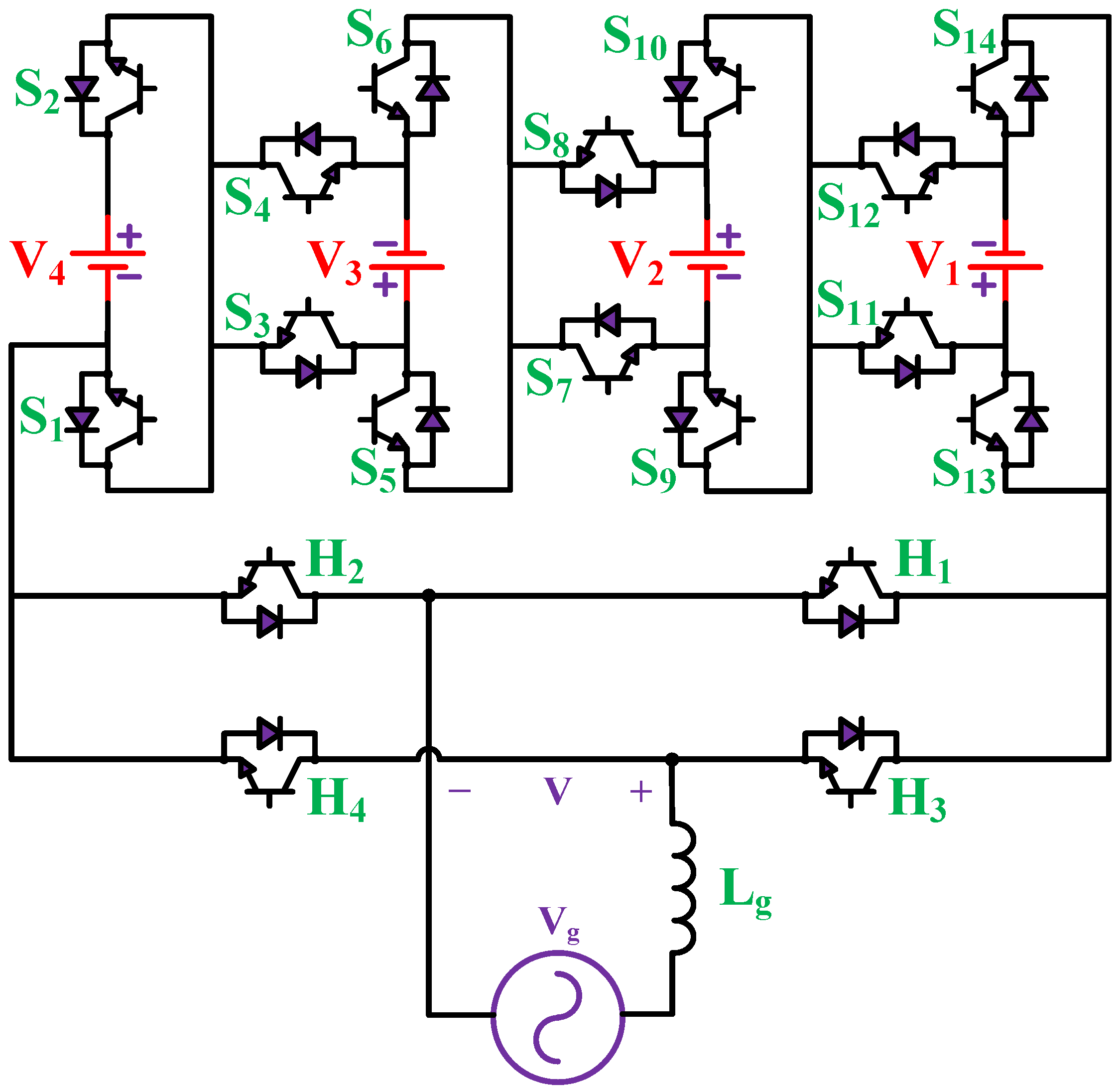
2. Proposed MWMLI Topology

The single-phase MWMLI topology to obtain an 81-level output voltage is shown in Figure 2. It uses a total of eighteen unidirectional switches (S1–S14 and H1–H4) and four DC power sources (V1–V4) with a golden ratio of 1:3:9:27. The DC voltage source V1 has the lowest value as VDC in the circuit. The H-bridge comprised of switches H1–H4 ensures the generation of negative voltage levels corresponding to each positive voltage level. With the golden ratio of 1:3:9:27, an 81-level (40 positives, 40 negatives, and a zero level) output voltage is obtained from the MWMLI configuration. The switching states for the gate pulses of MWMLI for all the voltage level magnitudes are shown in Table 1.
The generic equations to calculate the number of DC power sources and the number of switching devices based on the number of voltage levels is given as:
N D C = log 3 ( N L )
N S = 2 ( 2 N D C + 1 )
Using the golden ratio of DC power sources, the maximum number of levels for MWMLI topology is:
N L = 3 N D C
The peak output voltage for the MWMLI topology is given as:
V o , p k = ( N L 1 ) 2 V D C
where V D C is the lowest DC voltage source value equal to V1 in this case.
The maximum blocking voltage (MBV), also denoted as the total standing voltage in [23], is the sum of the reverse blocking voltage of individual switching devices in the MWMLI topology. The MBV is an important parameter in the selection of suitable switches for a given power and voltage rating of an inverter. MBV for the MWMLI topology is given as:
M B V = i = 1 14 V S i + 4 V H 1
Since the MWMLI topology is using the golden ratio of DC power sources,
M B V = 266 V D C

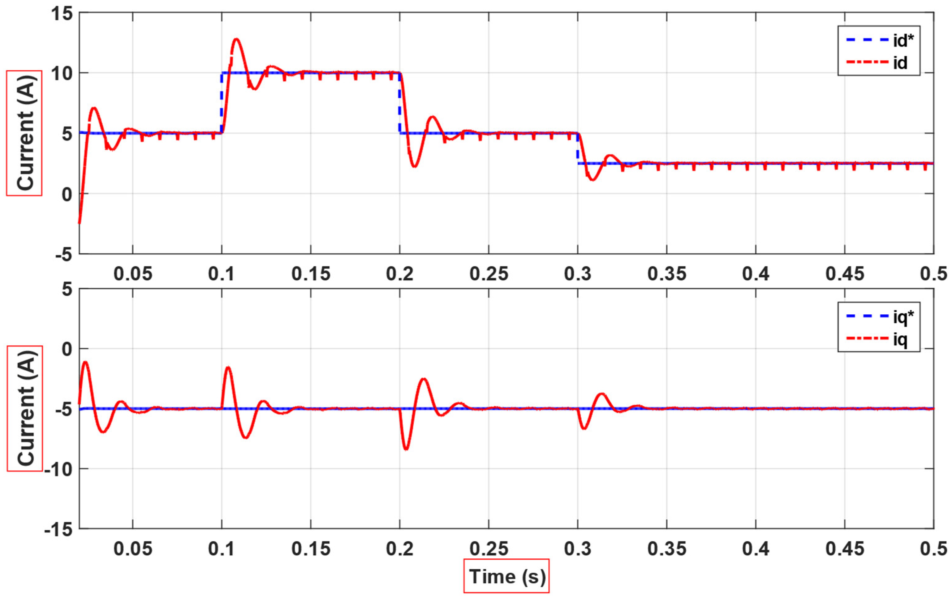
3. Controller Implementation

The closed-loop control of the MWMLI topology for grid integration is developed based on its modeling in the synchronously rotating reference frame. In the modeling, the coupling inductance between the grid and the inverter is considered lossless. The state equations for the MWMLI using Park transformation [24,25] are given as:
v d = L d i d d t ω L i q + v g d
v q = L d i q d t + ω L i d + v g q
where, v g d and v g q are the grid side d-axis and q-axis voltages, respectively. In Equations (7) and (8), the coupling terms ω L i q and ω L i d on the grid side should be decoupled on the controller side to nullify the coupling effect and design a proper PI controller for active and reactive power flow to the grid. The decoupled form of Equations (7) and (8) is given as:
v d = L d i d d t + ω L i q + v g d
v q = L d i q d t ω L i d + v g q
where, v d and v q are the control inputs for the PWM generation block in Figure 3.

Binary Search Nearest Level Algorithm

The binary search nearest level algorithm (BSNLA) is used to generate the switching pulses based on the given reference voltage. This algorithm works as follows:
The reference signal v α is sampled at a sufficient sampling rate above the Nyquist rate and the amplitude of every sample serves as the search index for the lookup table (LUT) of switching states. Based on the BSNLA, the switching states array for a voltage level nearest to the sample amplitude is sent to the output of the BSNLA/LUT block, as in Figure 3. The output of the BSNLA/LUT block is fed to the MWMLI. The flow chart of the implementation of BSNLA is shown in Figure 4.

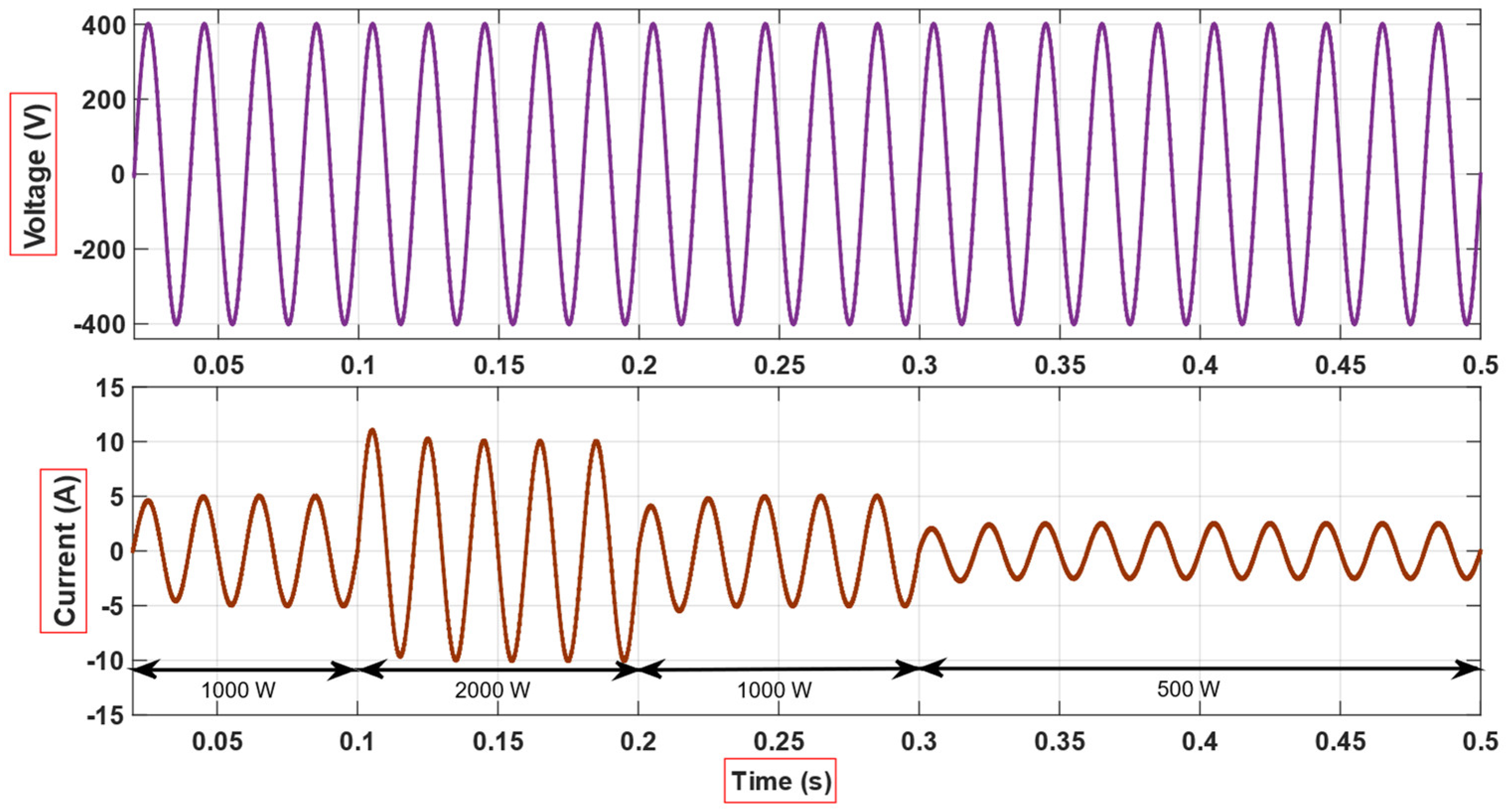
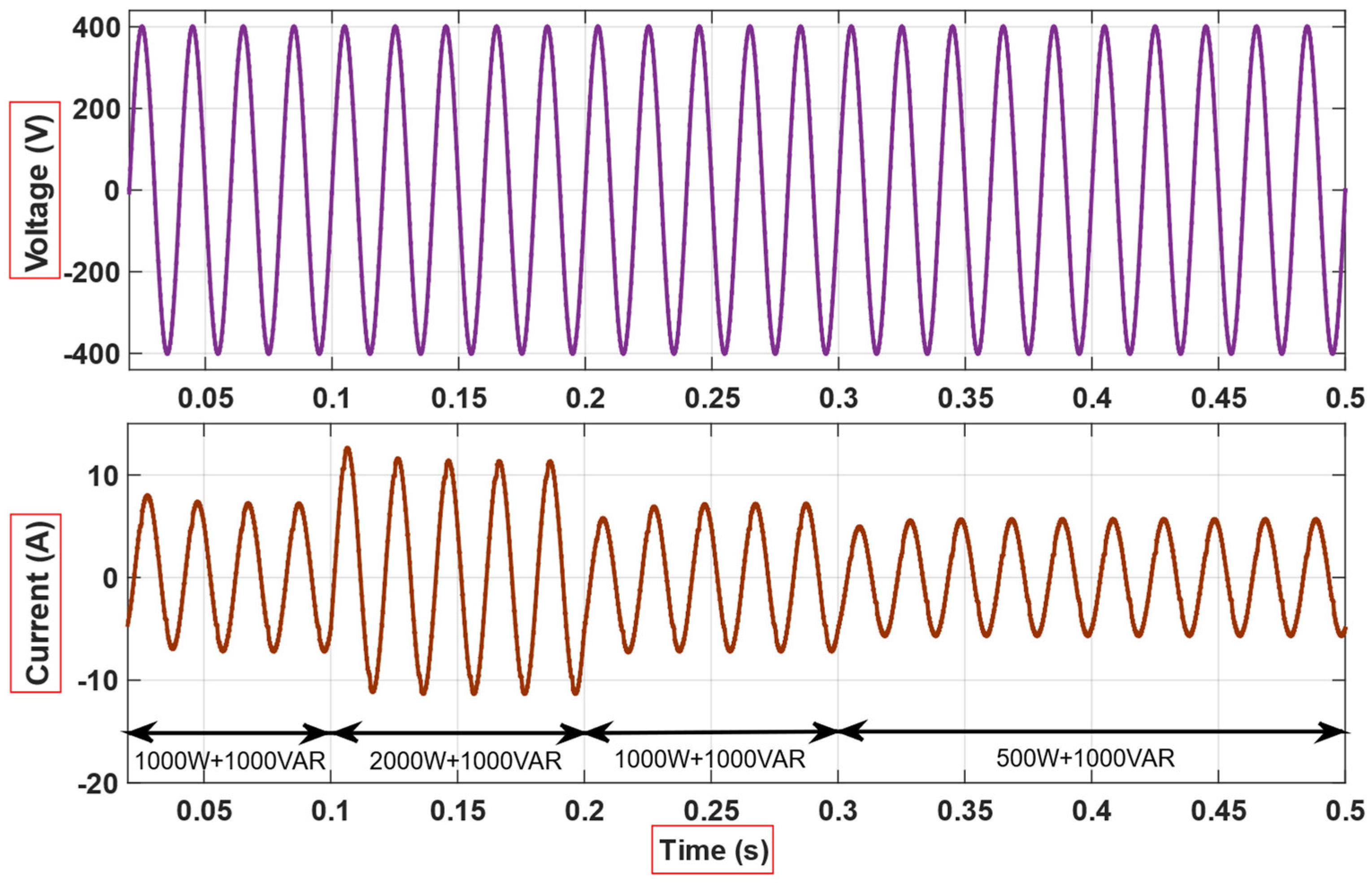
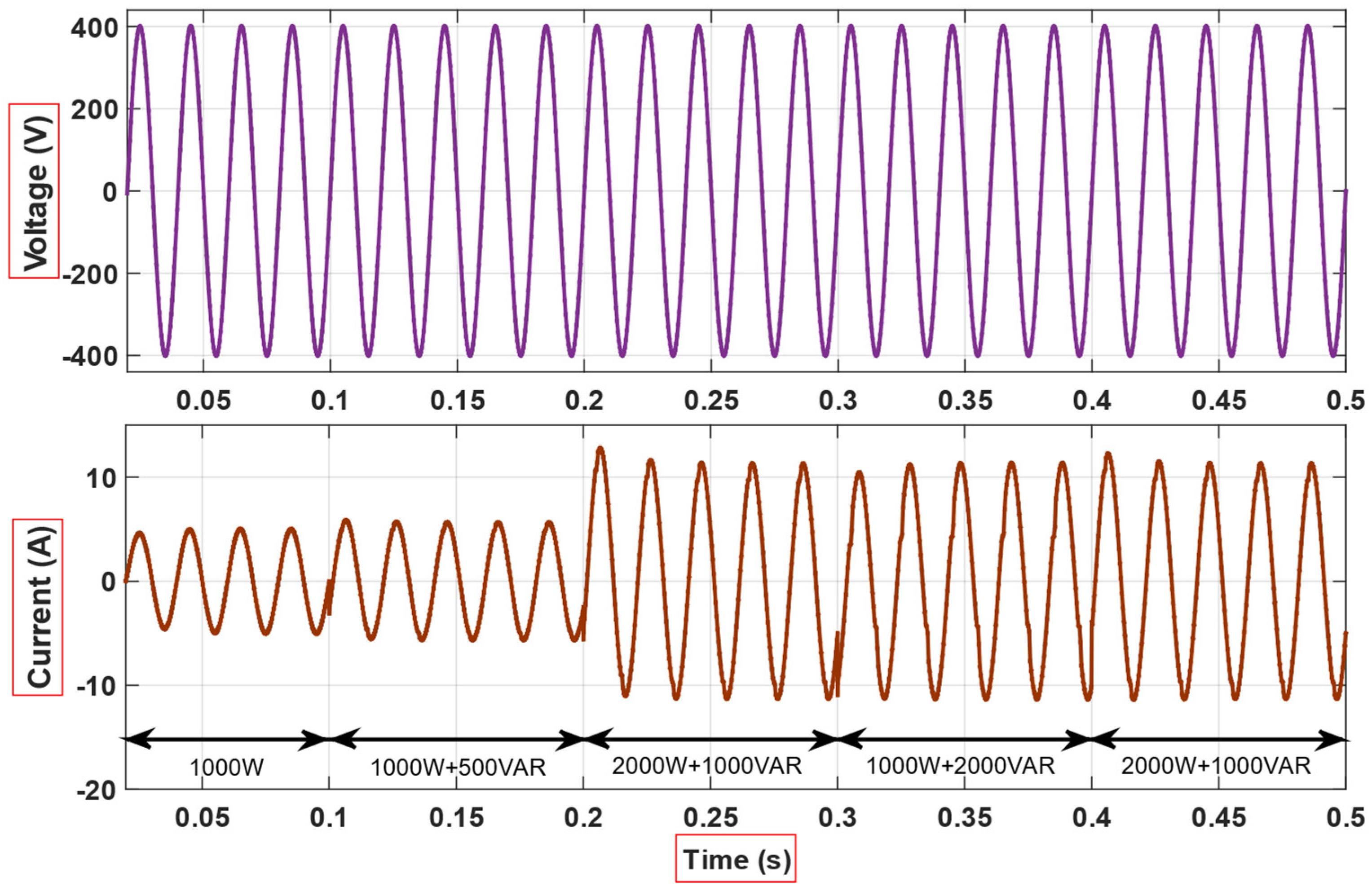
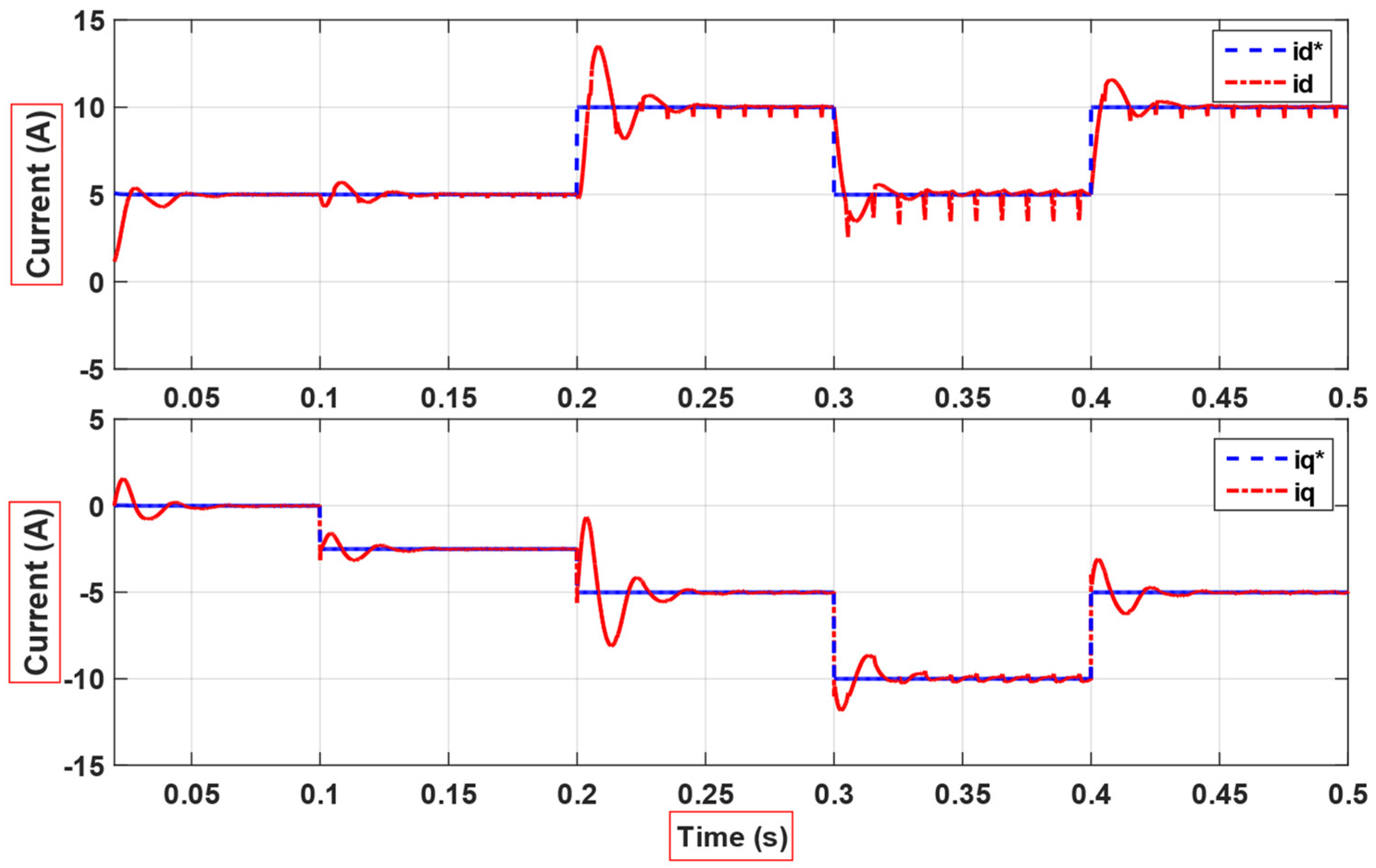
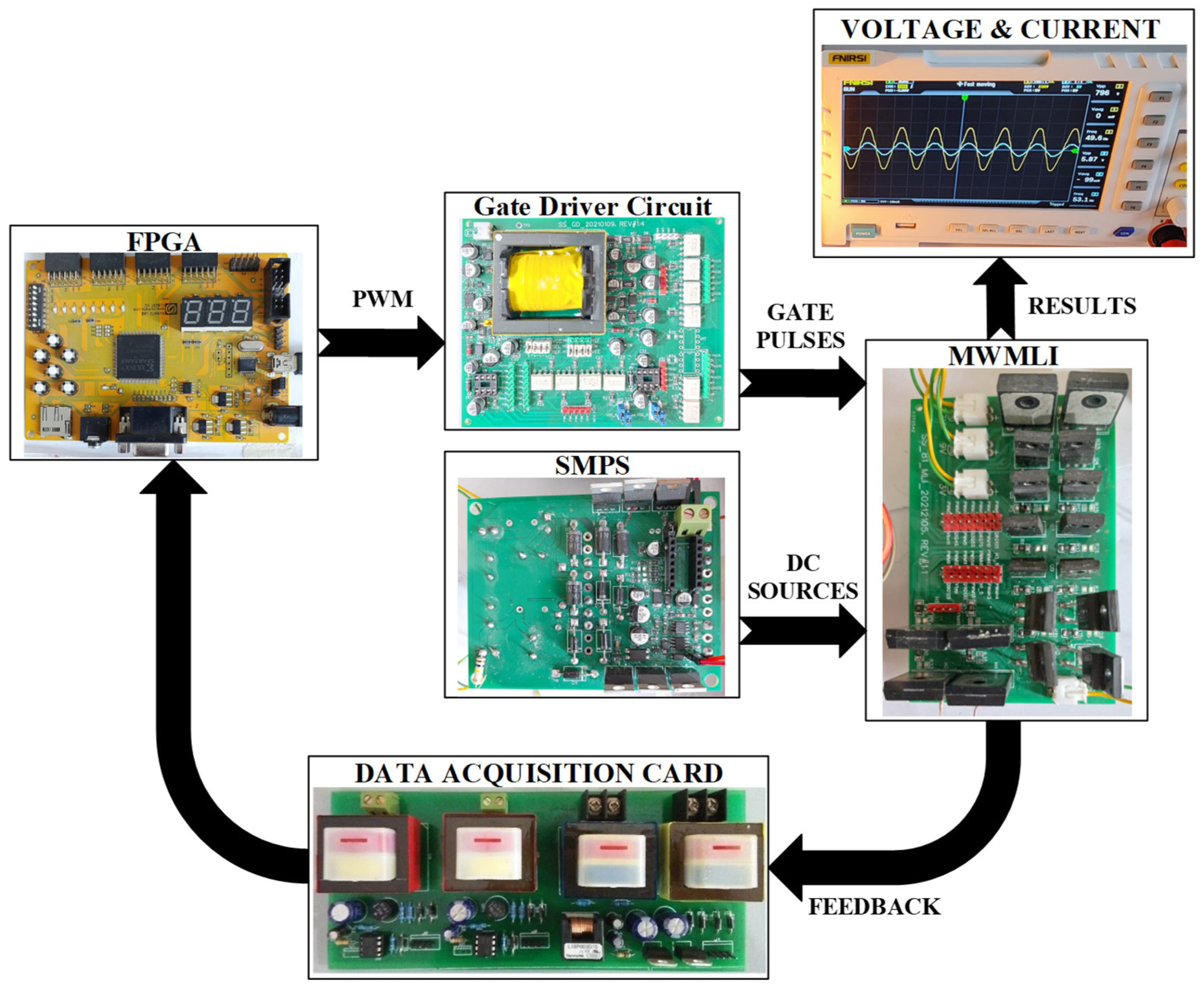
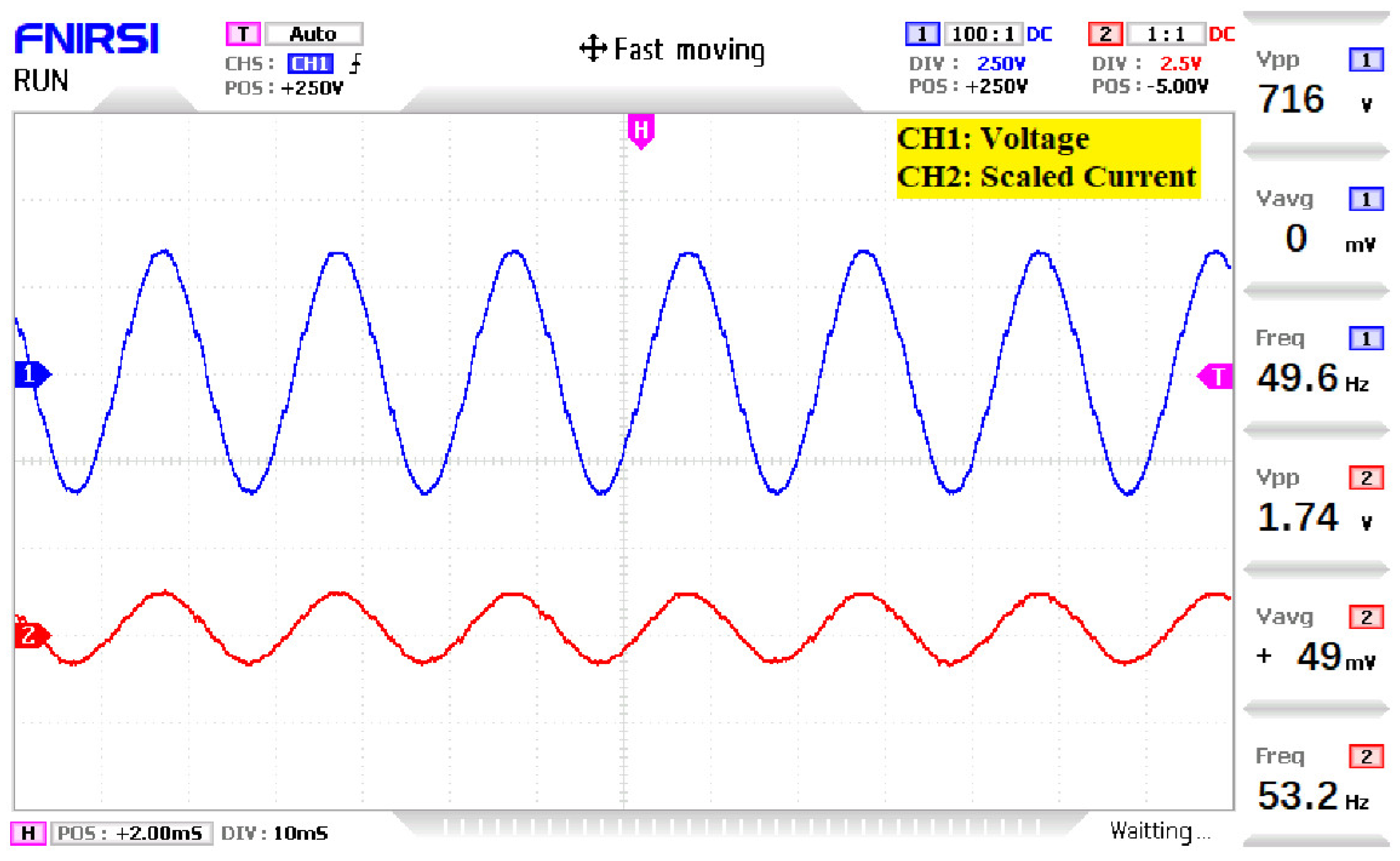
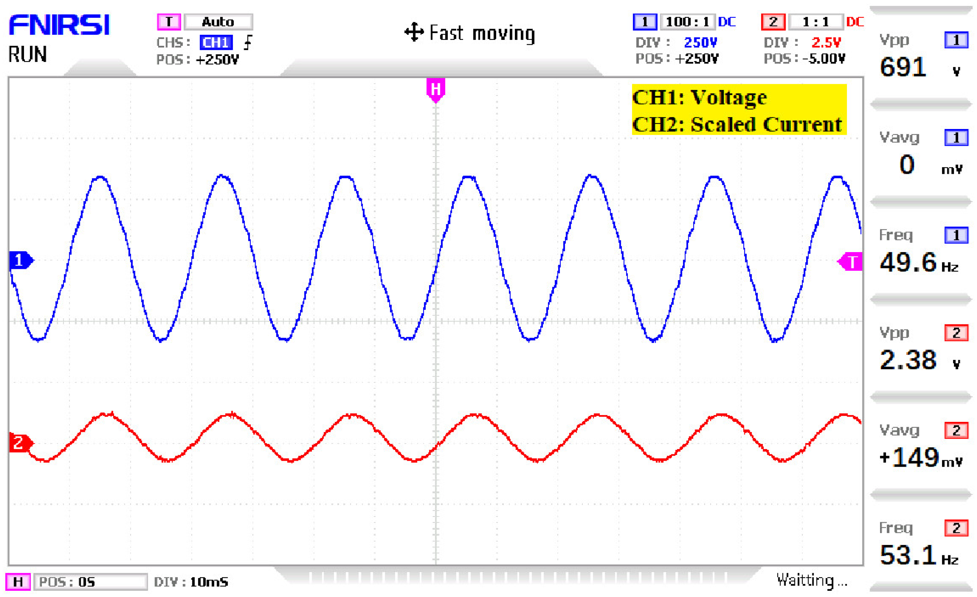
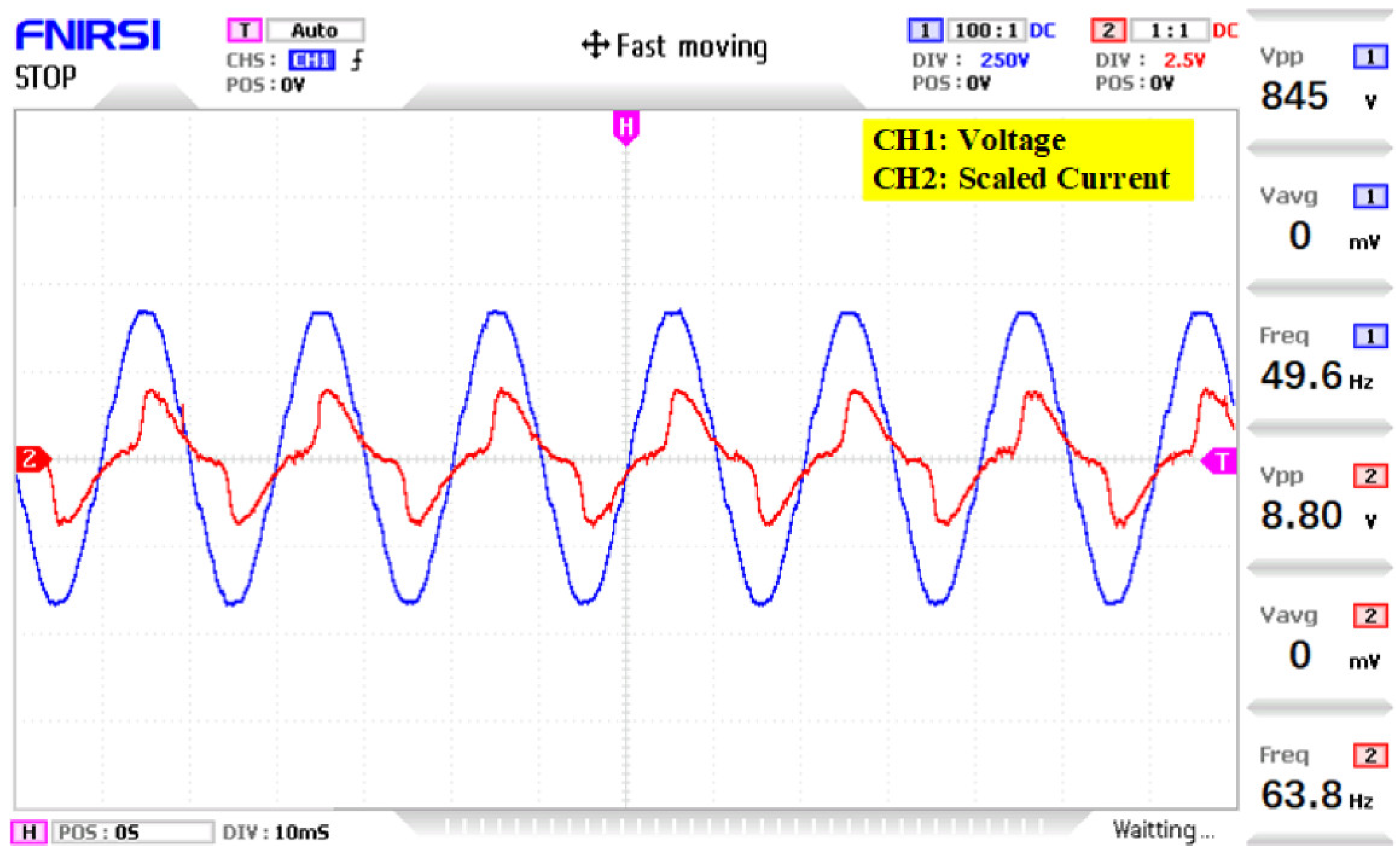
4. Simulation and Experimental Results

The topology of MWMLI is simulated in MATLAB/Simulink using the BSNL algorithm for grid-tied operations. An ideal voltage source is taken as a grid and the output of the MWMLI is connected to the grid through a lossless inductance L g . The parameters for the simulation of MWMLI topology in MATLAB/Simulink are shown in Table 2. Active and reactive power is set as a reference, which is then dynamically step changed multiple times to different values during the simulation to observe the transient and steady-state operation of the grid-connected MWMLI. The simulation results for different combinations of active and reactive power flow to the grid are presented as the simulation cases (SC).
SC-1: Using the parameters specified in Table 2, the circuit of MWMLI along with BSNLA is simulated in MATLAB/Simulink and the resulting waveforms of voltage and current for dynamic active power flow to the grid are shown in Figure 5. The reference and the estimated d-axis currents corresponding to the current waveform in Figure 5 are plotted in Figure 6. Because of the active power flow only, the q-axis component of the current is zero and hence ignored in the plot.
SC-2: For a dynamic active and fixed reactive power flow to the grid, the MWMLI is simulated and the resulting voltage and current waveforms are shown in Figure 7. The reference and the estimated dq-axis currents corresponding to the current waveform of Figure 7 are plotted in Figure 8 as separate subplots for d-axis and q-axis components. As there is a non-zero reactive power flow to the grid in this case, the q-axis component is non-zero as compared to the previous case. It can be seen from Figure 8 that the q-axis component is non-zero and has a consant value of −5, whereas the d-axis component value is dynamically step changed proportional to the step change value in the active power flow.
SC-3: The simulation of MWMLI for various combinations of active and reactive power flow to the grid at a lagging power factor is also carried out in MATLAB/Simulink. The resulting waveforms of voltage and current showing dynamic step changes in the current proportional to the power flow are shown in Figure 9. The reference and the estimated dq-axis currents corresponding to the current waveform in Figure 9 are plotted in Figure 10 as separate subplots for d-axis and q-axis components. In this case, as both the active and reactive power flow commands are given to the controller dynamically, the resulting step changes are reflected in the d-axis and q-axis components of the current that are shown in Figure 10 as separate subplots.
The hardware implementation of the MWMLI is carried out using real components. To test the prototype, the DC power sources are built using switch mode power supplies (SMPS). Figure 11 shows the hardware circuit for the prototype testing of the MWMLI operation. The Elbert v2 FPGA board is used for the implementation of switching control for the MWLMI. The other hardware components used in the prototype development are listed in Table 3. The experimental voltage and current waveforms at unity power factor and 0.85 lagging power factor are shown in Figure 12 and Figure 13, respectively.
The hardware prototype of the proposed MWMLI topology is tested for a non-linear independent load to determine the effectiveness when operating as a standalone. The resuting waveforms for voltage and current are shown in Figure 14. Another experiment with the voltage and current waveforms shown in Figure 15 is also performed at a modulation index of 0.88. It can be observed from Figure 15 that the voltage waveform is slightly distorted after decreasing the modulation index from unity. This is because the number of voltage levels are now reduced from 81, as some voltage levels are skipped.
The proposed grid-connected system is analyzed for efficiency computation at different loading conditions. Based on the loss and efficiency analysis equations presented in [23], the losses of the MWMLI are computed to determine the efficiency of the grid-connected operation. The efficiency of the grid-connected MWMLI system for unity power factor loads is above 90%, whereas the efficiency for lagging power factor loads is slightly less than 90%. The plot showing the efficiency trend versus power output is shown in Figure 16.

5. Discussion

The grid-connected 81-level MWMLI is implemented in MATLAB/Simulink for the simulation, and its hardware prototype is developed to verify the simulation results. The waveform of the current for the dynamic power flow to the grid shows that at the locations of step changes in the load, the controller efficiently tracks the step changes within two cycles of the grid frequency. The waveform results show that any combination of active and reactive power flow to the grid has approximately no impact on the waveshape of the MWMLI voltage. Since the THD of the MWMLI, as reported in [23], is 1.04%, there is no need for an output filter for the interconnection with the electric grid. The efficiency graph reveals that the MWMLI topology has an efficiency above 90% at unity power factor, whereas its efficiency for 0.85 lagging power factor loads is slightly less than 90%. The efficiency plot also shows that the efficiency starts to decrease slightly by increasing the output power for unity power factor loads. This effect is justified, as the conduction loss is proportional to the square of the current. A shortcoming of the proposed MWMLI topology is that it has slightly less efficiency when compared with other MLI topologies in the literature. However, the output power quality is improved due to the increased output voltage levels compared to those topologies. Another justification for this drawback is that there is no need for an output filter for the interconnection with the grid, as the MWMLI has better output voltage quality.

6. Conclusions

This paper presents a single-phase grid-connected 81-level MWMLI for real-time power flow to an electric grid. The proposed configuration uses an 81-level MWMLI that has eighteen switching devices and requires four DC power sources. The modeling of the controller for the generation of PWM pulses is carried out in a synchronously rotating reference frame along with the BSNL algorithm. The modeling of the single-phase system uses the concept of transformation of voltages and currents directly from αβ to the dq frame, with the β-components obtained virtually by delaying the α-component. The proposed grid-connected system is simulated in MATLAB/Simulink, and the simulation results are also verified by testing the hardware prototype. The key features of the proposed configuration, such as higher efficiency, THD within standards, and no filter requirement, make it suitable for grid-connected applications. The MWMLI system can be used to extract energy from renewable energy sources, such as PV systems, DESs, and other inverter based resources (IBRs). The energy extraction with high efficiency using the proposed MWMLI topology has a wide range of applications, such as standalone industrial systems, as well as grid-connected systems. The proposed MWMLI system also has good stability in terms of step changes in the load. As modern smart grids are being integrated with IBRs at multiple locations and the overall stability of the system is directly dependent on the stability of the individual components of the systems, the proposed scheme provides good stability under various loading conditions.

Author Contributions

Conceptualization: S.A.; methodology: S.A. and F.A.; software: S.A.; validation: S.A.; formal analysis: S.A., M.A.S. and L.J.; investigation: S.A. and Z.L.; resources: S.A.; data curation: S.A.; writing—original draft preparation: S.A.; writing—review and editing: F.A., K.H., K.M.A., S.A., S.A.R.K. and M.A.S.; visualization: S.A., S.A.R.K. and M.A.S.; supervision: L.J., Z.L., K.M.A., K.H., S.A.R.K. and M.A.S.; funding acquisition: Z.L. All authors have read and agreed to the published version of the manuscript.

Funding

This research received no external funding.

Institutional Review Board Statement

Not applicable.

Informed Consent Statement

Not applicable.

Data Availability Statement

Not applicable.

Conflicts of Interest

The authors declare no conflict of interest.

References

  1. Raveendhra, D.; Pathak, M.K. Three-phase capacitor clamped boost inverter. IEEE Trans. Emerg. Sel. Top. Power Electron. 2019, 7, 1999–2011. [Google Scholar] [CrossRef]
  2. Yuan, X.; Barbi, I. Fundamentals of a new diode clamping multilevel inverter. IEEE Trans. Power Electron. 2000, 15, 711–718. [Google Scholar] [CrossRef]
  3. Mahdavi, M.S.; Gharehpetian, G.B.; Mahdavi, Z.; Keyhani, A. Eighteen-Step Inverter: A low-loss three-phase inverter for low-cost standalone applications. IEEE Trans. Emerg. Sel. Top. Power Electron. 2021, 9, 970–979. [Google Scholar] [CrossRef]
  4. Vasu, R.; Chattopadhyay, S.K.; Chakraborty, C. Asymmetric cascaded H-bridge multilevel inverter with single dc source per phase. IEEE Trans. Ind. Electron. 2020, 67, 5398–5409. [Google Scholar] [CrossRef]
  5. Darmian, S.Y.; Barakati, S.M. A new asymmetric multilevel inverter with reduced number of components. IEEE Trans. Emerg. Sel. Top. Power Electron. 2020, 8, 4333–4342. [Google Scholar] [CrossRef]
  6. Kumar, A.; Raghuram, M.; Pilli, N.K.; Singh, S.K.; Pan, X.; Xiong, X. A generalized switched inductor cell modular multilevel inverter. IEEE Trans. Ind Appl. 2020, 56, 507–518. [Google Scholar] [CrossRef]
  7. Lee, S.S.; Lim, C.S.; Siwakoti, Y.P.; Lee, K.B. Dual T-type five-level cascaded multilevel inverter with double voltage boosting gain. IEEE Trans. Power Electron. 2020, 35, 9522–9529. [Google Scholar] [CrossRef]
  8. Rahim, O.A.; Wang, H. Five-level one-capacitor boost multilevel inverter. IET Power Electron. 2020, 13, 2245–2251. [Google Scholar] [CrossRef]
  9. Ali, J.S.M.; Almakhles, D.J.; Ibrahim, S.A.A.; Alyami, S.; Selvam, S.; Bhaskar, M.S. A generalized multilevel inverter topology with reduction of total standing voltage. IEEE Access 2020, 8, 168941–168950. [Google Scholar] [CrossRef]
  10. Venkataramanaiah, J.; Suresh, Y.; Panda, A.K. A review on symmetric, asymmetric, hybrid and single dc sources based multilevel inverter topologies. Renew. Sust. Energy Rev. 2017, 76, 788–812. [Google Scholar] [CrossRef]
  11. Babaei, E.; Alilu, S.; Laali, S. A new general topology for cascaded multilevel inverters with reduced number of components based on developed H-bridge. IEEE Trans. Ind. Electron. 2014, 61, 3932–3939. [Google Scholar] [CrossRef]
  12. Siddique, M.D.; Mekhilef, S.; Shah, N.M.; Memon, M.A. Optimal design of a new cascaded multilevel inverter topology with reduced switch count. IEEE Access 2019, 7, 24498–24510. [Google Scholar] [CrossRef]
  13. Siddique, M.D.; Mekhilef, S.; Shah Ali, J.S.M.; Meraj, M.; Iqbal, A. A new single phase single switched-capacitor based nine-level boost inverter topology with reduced switch count and voltage stress. IEEE Access 2019, 7, 174178–174188. [Google Scholar] [CrossRef]
  14. Mahato, B.; Majumdar, S.; Jana, K.C. Reduction in controlled power switches for a single-phase novel multilevel inverter. Int. J. Electron. 2019, 106, 1200–1215. [Google Scholar] [CrossRef]
  15. Mahato, B.; Majumdar, S.; Jana, K.C. Reduction of power electronic devices in a single-phase generalized multilevel inverter. J. Circuits Sys. Comp. 2020, 29, 2050093. [Google Scholar] [CrossRef]
  16. Dhanamjayulu, C.; Devalraju, P.; Sanjeevikumar, P.; Pandav, M.K.; Jens, H.B.; Frede, B. Design and implementation of seventeen level inverter with reduced components. IEEE Access 2021, 9, 16746–16760. [Google Scholar] [CrossRef]
  17. Samadaei, E.; Sheikholeslami, A.; Gholamian, S.A.; Adabi, J. A square T-type (ST-type) module for asymmetrical multilevel inverters. IEEE Trans. Power Electron. 2018, 33, 987–996. [Google Scholar] [CrossRef]
  18. Samadaei, E.; Kaviani, M.; Bertilsson, K. A 13-levels module (K-type) with two dc sources for multilevel inverters. IEEE Trans. Ind. Electron. 2019, 66, 5186–5196. [Google Scholar] [CrossRef]
  19. Khodaparast, A.; Adabi, J.; Rezanejad, M. A step-up switched-capacitor multilevel inverter based on 5-level t-type modules. IET Power Electron. 2019, 12, 483–491. [Google Scholar] [CrossRef]
  20. Dhanamjayulu, C.; Arunkumar, G.; Pandian, B.J.; Kumar, C.V.R.; Kumar, M.P.; Jerin, A.R.A.; Venugopal, P. Real-time implementation of a 31-level asymmetrical cascaded multilevel inverter for dynamic loads. IEEE Access 2019, 7, 51254–51266. [Google Scholar] [CrossRef]
  21. Sid-Ali, A.; Kamal, M.; Abderrezzak, C.; Bruno, F. Multilevel inverter topology for renewable energy grid integration. IEEE Trans. Ind. Electron. 2017, 64, 8855–8866. [Google Scholar]
  22. Mahfuz-Ur-Rahman, A.M.; Islam, M.R.; Muttaqi, K.M.; Sutanto, D. Model predictive control for a new magnetic linked multilevel inverter to integrate solar photovoltaic systems with the power grids. IEEE Trans. Ind Appl. 2020, 56, 7145–7155. [Google Scholar] [CrossRef]
  23. Ahmed, S.; Saqib, M.A.; Kashif, S.A.R. Modified W-type configuration for a single-phase reduced parts count 81-level inverter. PLoS ONE 2022, 17, e0269714. [Google Scholar] [CrossRef] [PubMed]
  24. Pigazo, A.; Moreno, V.M.; EstEbanez, E.J. A recursive park transformation to improve the performance of synchronous reference frame controllers in shunt active power filters. IEEE Trans. Power Electron. 2009, 24, 2065–2074. [Google Scholar] [CrossRef] [Green Version]
  25. Flah, A.; Khan, I.A.; Agarwal, A.; Sbita, L.; Marcelo, G. Simoes Field-oriented control strategy for double-stator single-rotor and double-rotor single-stator permanent magnet machine: Design and operation. Comput. Electr. Eng. 2021, 90, 106953. [Google Scholar] [CrossRef]
Figure 1. PV scheme for the four DC power sources of 81-level MWMLI.
Sustainability 14 16545 g001
Figure 2. Proposed configuration of grid-connected 81-level MWMLI.
Sustainability 14 16545 g002
Figure 3. Block diagram of the controller for grid-connected 81-level MWMLI.
Sustainability 14 16545 g003
Figure 4. Flow chart of BSNL algorithm.
Sustainability 14 16545 g004
Figure 5. MWMLI voltage and current for a non-zero active and zero reactive power flow to the grid.
Sustainability 14 16545 g005
Figure 6. Reference and estimated d-axis current components for the current shown in Figure 5.
Sustainability 14 16545 g006
Figure 7. MWMLI voltage and current for dynamic active and fixed reactive power flow to the grid.
Sustainability 14 16545 g007
Figure 8. Reference and estimated dq-axis current components for the current shown in Figure 7.
Sustainability 14 16545 g008
Figure 9. MWMLI voltage and current waveform for dynamic active and dynamic reactive power flow to the grid.
Sustainability 14 16545 g009
Figure 10. Reference and estimated dq-axis current components for the current shown in Figure 9.
Sustainability 14 16545 g010
Figure 11. Hardware prototype of MWMLI.
Sustainability 14 16545 g011
Figure 12. Experimental voltage and current waveforms at unity power factor for 0.4 kVA power flow.
Sustainability 14 16545 g012
Figure 13. Experimental voltage and current waveforms at 0.85 lagging power factor for 0.25 kVA.
Sustainability 14 16545 g013
Figure 14. Experimental voltage and current waveforms for a non-linear lagging loading while operating as a standalone system.
Sustainability 14 16545 g014
Figure 15. Experimental voltage and current waveforms with 0.88 modulation index and 0.1 kVA load at unity power factor.
Sustainability 14 16545 g015
Figure 16. Efficiency plot versus power output of the grid-connected MWMLI system.
Sustainability 14 16545 g016
Table 1. Switching states of MWMLI for all voltage magnitudes.
Sr. No.S1S3S5S7S9S11S13 | V O |
111111110
21111101VDC
311110102VDC
411110003VDC
511110014VDC
610101105VDC
710101116VDC
810101017VDC
910111108VDC
1010111119VDC
11101110110VDC
12101101011VDC
13101101112VDC
14101100113VDC
15010011014VDC
16010011115VDC
17010010116VDC
18010111017VDC
19010111118VDC
20010110119VDC
21010101020VDC
22010101121VDC
23010100122VDC
24011011023VDC
25011011124VDC
26011010125VDC
27011111026VDC
28011111127VDC
29011110128VDC
30011101029VDC
31011101130VDC
32011100131VDC
33001011032VDC
34001011133VDC
35001010134VDC
36001111035VDC
37001111136VDC
38001110137VDC
39001101038VDC
40001101139VDC
41001100140VDC
Table 2. Simulation parameters of MWMLI.
ParameterValueUnits
Inductance (Lg)1mH
Grid frequency (f)50Hz
Lowest DC voltage (VDC)10V
Value of Kp100-
Value of Ki8000-
Grid voltage amplitude (Vg)400Vpeak
Table 3. Hardware components used for prototype development.
ParameterQuantity/Value
IRFP4506
R6015ENX8
UCC28700DBVR2
IRF320512
CSD19534Q5A2
T7503424242
TLP25016
KNF6450A4
IR21032
Publisher’s Note: MDPI stays neutral with regard to jurisdictional claims in published maps and institutional affiliations.

