
Comprehensive Analysis of Microgrids Configurations and Topologies


Abstract
:1. Introduction
2. Classification of MGs
3. MGs Topologies
- Control mechanisms of the dynamic characteristics of the DGs resources;
- Voltage regulation and frequency for power balance both in island mode and connected to the EPS;
- The transition between operation modes to detect situations that cause changes;
- Economic dispatch to share the load between different DGs;
- Renewable sources are available;
- Minimum impact on the distribution network;
- Coordination between DERs.
3.1. Control Structures of DC and AC MGs
3.1.1. Control Method
PV Systems
Centralized Inverter Configuration
Inverter Chain Configuration
Microinverter Configuration
Wind Systems
Induction Generator
Double-Winding Induction Generator
Synchronous Generator
Permanent-Magnet Synchronous Generator
3.1.2. Load Sharing Techniques
Centralized control
Master and Slave Control
Average Load Sharing Control
Ring Control
3.2. Hybrid MG Topologies
3.2.1. Coupled AC
Partially Isolated Configuration
Completely Isolated Configuration
3.2.2. Decouple AC
Two-Stage Completely Isolated Configuration
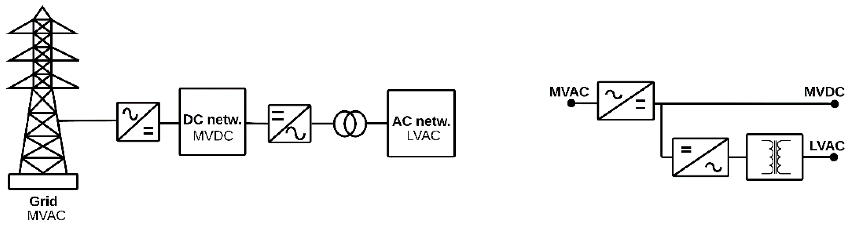
Two-Stage Partially Isolated Configuration
Three-Stage Partially Isolated Configuration
3.2.3. Multiple MGs
AC—DC
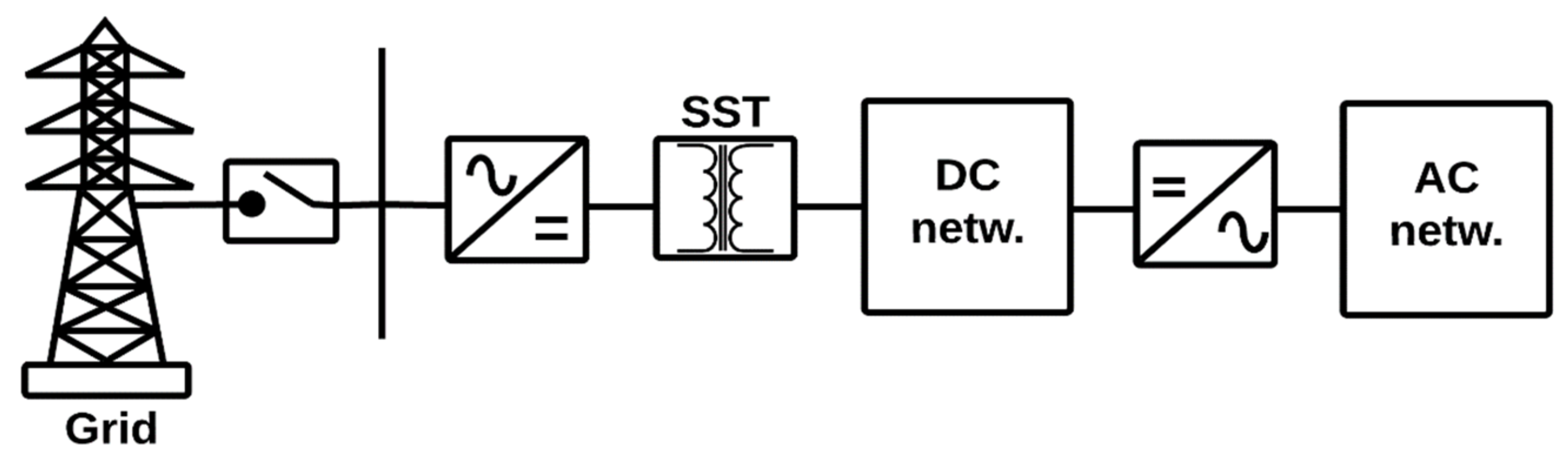
Based on SST
3.3. 3-NET
3.4. Classification by Configuration
3.4.1. Cascade Type
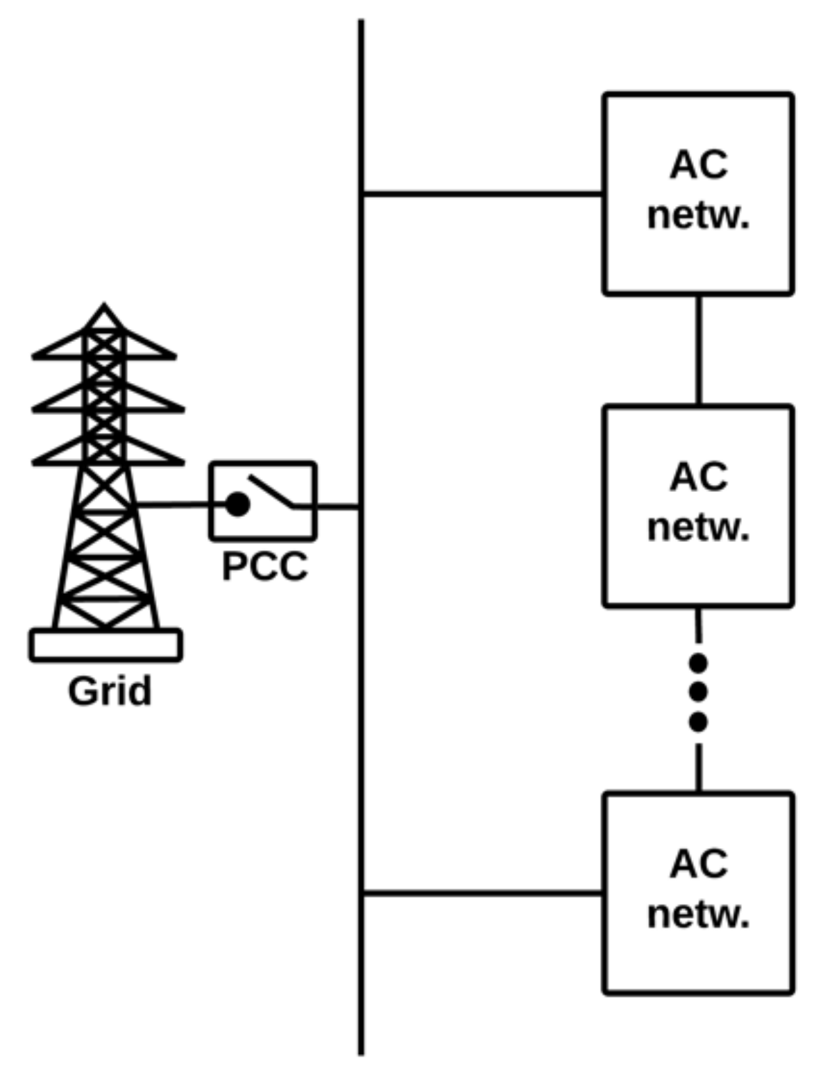
3.4.2. Parallel Type
3.5. Summary of the MG Characteristics
4. Conclusions
Author Contributions
Funding
Institutional Review Board Statement
Informed Consent Statement
Data Availability Statement
Acknowledgments
Conflicts of Interest
References
- Meng, L.; Sanseverino, E.R.; Luna, A.; Dragicevic, T.; Vasquez, J.C.; Guerrero, J.M. Microgrid supervisory controllers and energy management systems: A literature review. Renew. Sustain. Energy Rev. 2016, 60, 1263–1273. [Google Scholar] [CrossRef]
- Unamuno, E.; Barrena, J.A. Hybrid ac/dc microgrids—Part I: Review and classification of topologies. Renew. Sustain. Energy Rev. 2015, 52, 1251–1259. [Google Scholar] [CrossRef]
- Gómez, Y.A.G.; Garcia, N.T.; Velasco, F.E.H. Acondicionador Unificado de Calidad de la Potencia en Topología Dual iUPQC para Compensación Activa de Sobretensiones Transitorias. INGE CUC 2017, 13, 112–117. [Google Scholar] [CrossRef]
- Patnaik, B.; Mishra, M.; Bansal, R.C.; Jena, R.K. MODWT-XGBoost based smart energy solution for fault detection and classification in a smart microgrid. Appl. Energy 2021, 285, 116457. [Google Scholar] [CrossRef]
- IEEE. IEEE Standard for the Testing of Microgrid Controllers. IEEE Study 2018, 2018, 1–42. [Google Scholar] [CrossRef]
- IEC. IEC TS 62898-1:2017|Microgrids—Part 1: Guidelines for Microgrid Projects Planning and Specification; IEC: Geneva, Switzerland, 2017; Volume 33. [Google Scholar]
- Hossain, A.; Pota, H.R.; Hossain, J.; Blaabjerg, F. Evolution of microgrids with converter-interfaced generations: Challenges and opportunities. Int. J. Electr. Power Energy Syst. 2019, 109, 160–186. [Google Scholar] [CrossRef]
- Álvaro, R.; Menéndez, J. Casos de Microrredes; Orkestra: País Vasco, Spain, 2020; Volume 73. [Google Scholar]
- Gaona, E.E.; Mancera, P.A.; Trujillo, C.L. Sensores inalámbricos aplicada a una Microrred en modo “Isla” Routing Algorithm with topology reconfiguration for Wireless Sensor Network applied to microgrid in Island mode. Rev. UIS Ing. 2016, 15, 93–104. [Google Scholar] [CrossRef] [Green Version]
- Patnaik, B.; Mishra, M.; Bansal, R.C.; Jena, R.K. AC microgrid protection—A review: Current and future prospective. Appl. Energy 2020, 271, 115210. [Google Scholar] [CrossRef]
- Komala, K.; Kumar, K.P.; Cherukuri, S.H.C. Storage and non-Storage Methods of Power balancing to counter Uncertainty in Hybrid Microgrids—A review. J. Energy Storage 2021, 36, 102348. [Google Scholar] [CrossRef]
- Chen, X.; Ju, Y.; Zhang, R. Land-sea relay fishery networked microgrids under the background of cyber-physical fusion: Characteristics and key issues prospect. Inf. Process. Agric. 2021. Available online: https://login.ezproxy.cuc.edu.co/login?qurl=https://www.sciencedirect.com%2fscience%2fjournal%2faip%2f22143173 (accessed on 9 March 2021). [CrossRef]
- Ajoulabadi, A.; Ravadanegh, S.N.; Mohammadi-Ivatloo, B. Flexible scheduling of reconfigurable microgrid-based distribution networks considering demand response program. Energy 2020, 196, 117024. [Google Scholar] [CrossRef]
- Che, L.; Zhang, X.; Shahidehpour, M.; AlAbdulwahab, A.; Abusorrah, A. Optimal Interconnection Planning of Community Microgrids with Renewable Energy Sources. IEEE Trans. Smart Grid 2017, 8, 1054–1063. [Google Scholar] [CrossRef]
- Martin-Martínez, F.; Miralles, A.S.; Rivier, M. A literature review of Microgrids: A functional layer based classification. Renew. Sustain. Energy Rev. 2016, 62, 1133–1153. [Google Scholar] [CrossRef]
- Gadanayak, D.A. Protection algorithms of microgrids with inverter interfaced distributed generation units—A review. Electr. Power Syst. Res. 2021, 192, 106986. [Google Scholar] [CrossRef]
- Ortiz, L.; González, J.W.; Gutierrez, L.B.; Llanes-Santiago, O. A review on control and fault-tolerant control systems of AC/DC microgrids. Heliyon 2020, 6, e04799. [Google Scholar] [CrossRef]
- Laaksonen, H. Protection Principles for Future Microgrids. IEEE Trans. Power Electron. 2010, 25, 2910–2918. [Google Scholar] [CrossRef]
- Hooshyar, A.; Iravani, R. Microgrid Protection. Proc. IEEE 2017, 105, 1332–1353. [Google Scholar] [CrossRef]
- Hannan, M.; Tan, S.Y.; Al-Shetwi, A.Q.; Jern, K.P.; Begum, R. Optimized controller for renewable energy sources integration into microgrid: Functions, constraints and suggestions. J. Clean. Prod. 2020, 256, 120419. [Google Scholar] [CrossRef]
- Utkarsh, K.; Srinivasan, D.; Trivedi, A.; Zhang, W.; Reindl, T. Distributed Model-Predictive Real-Time Optimal Operation of a Network of Smart Microgrids. IEEE Trans. Smart Grid 2019, 10, 2833–2845. [Google Scholar] [CrossRef]
- Chandra, A.; Singh, G.K.; Pant, V. Protection techniques for DC microgrid—A review. Electr. Power Syst. Res. 2020, 187, 106439. [Google Scholar] [CrossRef]
- Wang, Y.; Rousis, A.O.; Strbac, G. On microgrids and resilience: A comprehensive review on modeling and operational strategies. Renew. Sustain. Energy Rev. 2020, 134, 110313. [Google Scholar] [CrossRef]
- Wei, P.; Chen, W. Microgrid in China: A review in the perspective of application. Energy Procedia 2019, 158, 6601–6606. [Google Scholar] [CrossRef]
- Jiayi, H.; Chuanwen, J.; Rong, X. A review on distributed energy resources and MicroGrid. Renew. Sustain. Energy Rev. 2008, 12, 2472–2483. [Google Scholar] [CrossRef]
- Nichols, D.; Stevens, J.; Lasseter, R.; Eto, J.; Vollkommer, H. Validation of the CERTS microgrid concept the CEC/CERTS microgrid testbed. In Proceedings of the 2006 IEEE Power Engineering Society General Meeting, Montreal, QC, Canada, 18–20 June 2006; IEEE: Piscataway, NJ, USA, 2006; p. 3. [Google Scholar]
- Issa, W.R.; El Khateb, A.H.; Abusara, M.A.; Mallick, T.K. Control Strategy for Uninterrupted Microgrid Mode Transfer During Unintentional Islanding Scenarios. IEEE Trans. Ind. Electron. 2018, 65, 4831–4839. [Google Scholar] [CrossRef] [Green Version]
- Priyadharshini, N.; Gomathy, S.; Sabarimuthu, M. A review on microgrid architecture, cyber security threats and standards. Mater. Today Proc. 2020. Available online: https://login.ezproxy.cuc.edu.co/login?qurl=https://doi.org%2f10.1016%2fj.matpr.2020.10.622 (accessed on 4 December 2020). [CrossRef]
- Cole, W.; Gates, N.; Mai, T. Exploring the cost implications of increased renewable energy for the U.S. power system. Electr. J. 2021, 34, 106957. [Google Scholar] [CrossRef]
- US EIA. February 2020 Monthly Energy Review; EIA: Washington, WA, USA, 2020.
- Lakatos, L.; Hevessy, G.; Kovács, J. Advantages and Disadvantages of Solar Energy and Wind-Power Utilization. World Future 2011, 67, 395–408. [Google Scholar] [CrossRef]
- Shahzad, U. A Quantitative Comparison of Wind and Solar Energy|Umair Shahzad—Academ-ia.edu. Durreesamin J. 2016, 7. Available online: https://www.academia.edu/32941924/A_Quantitative_Comparison_of_Wind_and_Solar_Energy (accessed on 4 December 2020).
- Fusheng, L.; Ruisheng, L.; Fengquan, Z. Composition and classification of the microgrid. In Microgrid Technology and Engineering Application; Academic Press: Cambridge, MA, USA, 2016; pp. 11–27. [Google Scholar] [CrossRef]
- Bordons, C.; Garcia-Torres, F.; Valverde-Isorna, L. Gestión Óptima de la Energía en Microrredes con Generación Renovable. Rev. Iberoam. Automática E Inf. Ind. 2015, 12, 117–132. [Google Scholar] [CrossRef] [Green Version]
- Ortiz, L.; Orizondo, R.; Águila, A.; González, J.W.; López, G.J.; Isaac, I. Hybrid AC/DC microgrid test system simulation: Grid-connected mode. Heliyon 2019, 5, e02862. [Google Scholar] [CrossRef] [Green Version]
- Dagar, A.; Gupta, P.; Niranjan, V. Microgrid protection: A comprehensive review. Renew. Sustain. Energy Rev. 2021, 149, 111401. [Google Scholar] [CrossRef]
- García, E.E.G.; Trujillo, C.L.R.; Cubides, H.E.R. Infraestructura de comunicaciones en microrredes eléctricas. Redes Ing. 2014, 5, 28–38. [Google Scholar] [CrossRef]
- Pourbehzadi, M.; Niknam, T.; Aghaei, J.; Mokryani, G.; Shafie-Khah, M.; Catalão, J.P.S. Optimal operation of hybrid AC/DC microgrids under uncertainty of renewable energy resources: A comprehensive review. Int. J. Electr. Power Energy Syst. 2019, 109, 139–159. [Google Scholar] [CrossRef]
- Nguyen, M.Y.; Yoon, Y.T. A Comparison of Microgrid Topologies Considering Both Market Operations and Reliability. Electr. Power Compon. Syst. 2014, 42, 585–594. [Google Scholar] [CrossRef]
- Basak, P.; Chowdhury, S.; Dey, S.H.N. A literature review on integration of distributed energy resources in the perspective of control, protection and stability of microgrid. Renew. Sustain. Energy Rev. 2012, 16, 5545–5556. [Google Scholar] [CrossRef]
- De Madrid, C.; De, G.; Inteligentes, R.; Energía, D.; Comunicación, Y. La Suma de Todos Guía de Redes Inteligentes de Energía y Comunicación; IDEA: Madrid, Spain, 2004. [Google Scholar]
- Fuentes, A. Estudio de Viabilidad y Requisitos Técnicos Necesarios Para la Implantación de una Micro-Red Eléctrica. Ph.D. Thesis, Universidad Argentina de la Empresa, Buenos Aires, Argentina, 2007. [Google Scholar]
- Gupta, A.; Doolla, S.; Chatterjee, K. Hybrid AC–DC Microgrid: Systematic Evaluation of Control Strategies. IEEE Trans. Smart Grid 2018, 9, 3830–3843. [Google Scholar] [CrossRef]
- Lotfi, H.; Khodaei, A. Hybrid AC/DC microgrid planning. Energy 2017, 118, 37–46. [Google Scholar] [CrossRef]
- Baran, M.; Mahajan, N. DC distribution for industrial systems: Opportunities and challenges. IEEE Trans. Ind. Appl. 2003, 39, 1596–1601. [Google Scholar] [CrossRef]
- Xu, L.; Chen, D. Control and Operation of a DC Microgrid with Variable Generation and Energy Storage. IEEE Trans. Power Deliv. 2011, 26, 2513–2522. [Google Scholar] [CrossRef]
- Guerrero, J.M.; Vasquez, J.C.; Matas, J.; de Vicuna, L.G.; Castilla, M. Hierarchical Control of Droop-Controlled AC and DC Microgrids—A General Approach toward Standardization. IEEE Trans. Ind. Electron. 2011, 58, 158–172. [Google Scholar] [CrossRef]
- Justo, J.J.; Mwasilu, F.; Lee, J.; Jung, J.-W. AC-microgrids versus DC-microgrids with distributed energy resources: A review. Renew. Sustain. Energy Rev. 2013, 24, 387–405. [Google Scholar] [CrossRef]
- Nehrir, M.H.; Wang, C.; Strunz, K.; Aki, H.; Ramakumar, R.; Bing, J.; Miao, Z.; Salameh, Z. A Review of Hybrid Renewable/Alternative Energy Systems for Electric Power Generation: Configurations, Control, and Applications. IEEE Trans. Sustain. Energy 2011, 2, 392–403. [Google Scholar] [CrossRef]
- Nejabatkhah, F.; Li, Y.W. Overview of Power Management Strategies of Hybrid AC/DC Microgrid. IEEE Trans. Power Electron. 2015, 30, 7072–7089. [Google Scholar] [CrossRef]
- Shi, G.; Han, H.; Liu, Y.; Su, M.; Liu, Z.; Sun, Y. A Common Second Frequency Control of Island Cascaded-type Microgrid. In Proceedings of the 2019 IEEE Energy Conversion Congress and Exposition (ECCE), Baltimore, MD, USA, 29 September–3 October 2019; IEEE: Piscataway, NJ, USA, 2019; pp. 5407–5410. [Google Scholar]
- Sun, Y.; Shi, G.; Li, X.; Yuan, W.; Su, M.; Han, H.; Hou, X. An f-P/Q Droop Control in Cascaded-Type Microgrid. IEEE Trans. Power Syst. 2018, 33, 1136–1138. [Google Scholar] [CrossRef]
- Ge, X.; Han, H.; Xiong, W.; Su, M.; Liu, Z.; Sun, Y. Locally-distributed and globally-decentralized control for hybrid series-parallel microgrids. Int. J. Electr. Power Energy Syst. 2020, 116, 105537. [Google Scholar] [CrossRef]
- Khan, H.A.U.; Al Hosani, M.; Zeineldin, H. Topology planning for autonomous MMGs: An ordered binary decision diagram-based approach. IET Smart Grid 2020, 3, 60–68. [Google Scholar] [CrossRef]
- Hernández Mora, J.; Trujillo Rodríguez, C.; Vallejo Lozada, W. Modelo de un sistema fotovoltaico interconectado. Tecnura 2013, 17, 26–34. [Google Scholar] [CrossRef]
- Trujillo Rodriguez, J. Hernandez Mora OFC. In Sistemas Fotovoltaicos y Sistemas Eólicos en Microrredes; UD E, Caldas U; Microrredes Electr. Primera, UD: Bogotá, Colombia, 2015; pp. 61–83. [Google Scholar]
- Hayman, A.K. Development of a High-Efficiency Solar Micro-Inverter. Ph.D. Thesis, Massachusetts Institute of Technology, Cambridge, MA, USA, 2008. [Google Scholar]
- Alvarez, J.M.G.; Targarona, J.C.G. Generación eólica empleando distintos tipos de generadores considerando su impacto en el sistema de potencia. Dyna 2011, 78, 95–104. [Google Scholar]
- ISE PRIFORSES. Photovoltaics Report; Fraunhofer: Freiburg, Germany, 2020. [Google Scholar]
- Mongrain, R.S.; Ayyanar, R. Control of nonideal grid-forming inverter in islanded microgrid with hierarchical control structure under unbalanced conditions. Int. J. Electr. Power Energy Syst. 2020, 119, 105890. [Google Scholar] [CrossRef]
- Brandao, D.I.; Araujo, L.; Caldognetto, T.; Pomilio, J.A. Coordinated control of three- and single-phase inverters coexisting in low-voltage microgrids. Appl. Energy 2018, 228, 2050–2060. [Google Scholar] [CrossRef]
- Pinto, J.O.C.P.; Moreto, M. Protection strategy for fault detection in inverter-dominated low voltage AC microgrid. Electr. Power Syst. Res. 2021, 190, 106572. [Google Scholar] [CrossRef]
- Chang, C.-Y.; Zhang, W. Distributed control of inverter-based lossy microgrids for power sharing and frequency regulation under voltage constraints. Automatica 2016, 66, 85–95. [Google Scholar] [CrossRef] [Green Version]
- Andishgar, M.H.; Gholipour, E.; Hooshmand, R.-A. An overview of control approaches of inverter-based microgrids in islanding mode of operation. Renew. Sustain. Energy Rev. 2017, 80, 1043–1060. [Google Scholar] [CrossRef]
- Khan, A.A.; Beg, O.A.; Alamaniotis, M.; Ahmed, S. Intelligent anomaly identification in cyber-physical inverter-based systems. Electr. Power Syst. Res. 2021, 193, 107024. [Google Scholar] [CrossRef]
- Trujillo, C.; Velasco, D.; Figueres, E.; Garcerá, G.; Ortega, R. Modeling and control of a push–pull converter for photovoltaic microinverters operating in island mode. Appl. Energy 2011, 88, 2824–2834. [Google Scholar] [CrossRef] [Green Version]
- Khan, O.; Xiao, W. Review and qualitative analysis of submodule-level distributed power electronic solutions in PV power systems. Renew. Sustain. Energy Rev. 2017, 76, 516–528. [Google Scholar] [CrossRef]
- Awan, M.A.I.; Raza, A.; Riaz, M.; Khalil, L.; Bhatti, K.L. Integration of sub-gradient based coordinate for multiple renewable generators in microgrid. Mater. Today Proc. 2021, 47, S64–S73. [Google Scholar] [CrossRef]
- Willenberg, D.; Winkens, A.; Linnartz, P. Impact of wind turbine generator technologies and frequency controls on the stable operation of medium voltage islanded microgrids. Electr. Power Syst. Res. 2020, 189, 106760. [Google Scholar] [CrossRef]
- Li, H.; Chen, Z. Overview of different wind generator systems and their comparisons. IET Renew. Power Gener. 2008, 2, 123–138. [Google Scholar] [CrossRef] [Green Version]
- Rosslyn-Smith, W.; De Abreu, N.V.A.; Pretorius, M. Exploring the indirect costs of a firm in business rescue. S. Afr. J. Account. Res. 2019, 34, 24–44. [Google Scholar] [CrossRef]
- Gaonkar, D.N. Investigation on Electromagnetic Transients of Distributed Generation Systems in the Microgrid. Electr. Power Compon. Syst. 2010, 38, 1486–1497. [Google Scholar] [CrossRef]
- Thakur, D.; Jiang, J. Design and Construction of a Wind Turbine Simulator for Integration to a Microgrid with Renewable Energy Sources. Electr. Power Compon. Syst. 2017, 45, 949–963. [Google Scholar] [CrossRef]
- Wunder, B.; Ott, L.; Kaiser, J.; Han, Y.; Fersterra, F.; Marz, M. Overview of different topologies and control strategies for DC micro grids. In Proceedings of the 2015 IEEE First International Conference on DC Microgrids (ICDCM), Atlanta, GA, USA, 7–10 June 2015; IEEE: Piscataway, NJ, USA, 2015; pp. 349–354. [Google Scholar]
- Wunder, B.; Ott, L.; Han, Y.; Kaiser, J.; Maerz, M. Voltage Control and Stabilization of Distributed and Centralized DC Micro Grids. In Proceedings of the PCIM Europe 2015; International Exhibition and Conference for Power Electronics, Intelligent Motion, Renewable Energy and Energy Management, Nuremberg, Germany, 19–20 May 2015; pp. 1–8. [Google Scholar]
- Dunham, H.; Cutler, D.; Mishra, S.; Li, X. Cost-optimal evaluation of centralized and distributed microgrid topologies considering voltage constraints. Energy Sustain. Dev. 2020, 56, 88–97. [Google Scholar] [CrossRef]
- Jmii, H.; Abbes, M.; Meddeb, A.; Chebbi, S. Centralized VSM control of an AC meshed microgrid for ancillary services provision. Int. J. Electr. Power Energy Syst. 2020, 115, 105450. [Google Scholar] [CrossRef]
- Chandra, A.; Singh, G.K.; Pant, V. Protection of AC microgrid integrated with renewable energy sources—A research review and future trends. Electr. Power Syst. Res. 2021, 193, 107036. [Google Scholar] [CrossRef]
- Carvalho Silveira, J.P.; dos Santos Neto, P.J.; dos Santos Barros, T.A.; Ruppert Filho, E.; Chandra, A.; Singh, G.K. Power management of energy storage system with modified interlinking converters topology in hybrid AC/DC microgrid. Int. J. Electr. Power Energy Syst. 2021, 130, 106880. [Google Scholar] [CrossRef]
- Chen, X.; Wang, Y.H.; Wang, Y.C. A novel seamless transferring control method for microgrid based on master-slave configuration. In Proceedings of the 2013 IEEE ECCE Asia Downunder, Melbourne, VIC, Australia, 3–6 June 2013; IEEE: Piscataway, NJ, USA, 2013; pp. 351–357. [Google Scholar]
- Wanichrojanarat, C.; Wirasanti, P. Control Strategy for Seamless Transition of Microgrid Using Battery Energy Storage System. In Proceedings of the 2018 53rd International Universities Power Engineering Conference (UPEC), Glasgow, UK, 4–7 September 2018; pp. 1–6. [Google Scholar] [CrossRef]
- Yan, Z.; Zhang, X.P. Master-slave wave farm systems based on energy filter with smoothed power output. Glob. Energy Interconnect. 2018, 1, 559–567. [Google Scholar] [CrossRef]
- Roslan, M.A.; Ahmed, K.H.; Finney, S.J.; Williams, B.W. Improved Instantaneous Average Current-Sharing Control Scheme for Parallel-Connected Inverter Considering Line Impedance Impact in Microgrid Networks. IEEE Trans. Power Electron. 2010, 26, 702–716. [Google Scholar] [CrossRef]
- Trip, S.; Han, R.; Cucuzzella, M.; Cheng, X.; Scherpen, J.; Guerrero, J. Distributed Averaging Control for Voltage Regulation and Current Sharing in DC Microgrids: Modelling and Experimental Validation. IFAC-PapersOnLine 2018, 51, 242–247. [Google Scholar] [CrossRef]
- Benahmed, S.; Riedinger, P.; Pierfederici, S. Distributed-based Integral Action for Current Sharing and Average Voltage Regulation in DC Microgrids. IFAC-PapersOnLine 2021, 54, 52–59. [Google Scholar] [CrossRef]
- Yuan, M.; Fu, Y.; Mi, Y.; Li, Z.; Wang, C. Hierarchical control of DC microgrid with dynamical load power sharing. Appl. Energy 2019, 239, 1–11. [Google Scholar] [CrossRef]
- Wu, T.-F.; Chen, Y.-K.; Huang, Y.-H. 3C strategy for inverters in parallel operation achieving an equal current distribution. IEEE Trans. Ind. Electron. 2000, 47, 273–281. [Google Scholar] [CrossRef]
- Toub, M.; Iii, R.D.R.; Maaroufi, M.; Aniba, G. Decentralized Hamiltonian Control of Multi-DER Isolated Microgrids with Meshed Topology. Energy Procedia 2019, 157, 1253–1265. [Google Scholar] [CrossRef]
- Zafeiratou, I.; Prodan, I.; Lefèvre, L.; Piétrac, L. Meshed DC microgrid hierarchical control: A differential flatness approach. Electr. Power Syst. Res. 2020, 180, 106133. [Google Scholar] [CrossRef]
- Mohammadi, S.; Ojaghi, M.; Jalilvand, A.; Shafiee, Q. A pilot-based unit protection scheme for meshed microgrids using apparent resistance estimation. Int. J. Electr. Power Energy Syst. 2021, 126, 106564. [Google Scholar] [CrossRef]
- Zhao, B.; Wang, X.; Lin, D.; Calvin, M.M.; Morgan, J.C.; Qin, R.; Wang, C. Energy Management of Multiple Microgrids Based on a System of Systems Architecture. IEEE Trans. Power Syst. 2018, 33, 6410–6421. [Google Scholar] [CrossRef]
- Agrawal, A.; Nalamati, C.S.; Gupta, R. Hybrid DC–AC Zonal Microgrid Enabled by Solid-State Transformer and Centralized ESD Integration. IEEE Trans. Ind. Electron. 2019, 66, 9097–9107. [Google Scholar] [CrossRef]
- Li, Y.; Sun, Q.; Qin, D.; Cheng, K.; Li, Z. Power Control of a Modular Three-Port Solid-State Transformer With Three-Phase Unbalance Regulation Capabilities. IEEE Access 2020, 8, 72859–72869. [Google Scholar] [CrossRef]
- Ullah, S.; Haidar, A.M.; Hoole, P.; Zen, H.; Ahfock, T. The current state of Distributed Renewable Generation, challenges of interconnection and opportunities for energy conversion based DC microgrids. J. Clean. Prod. 2020, 273, 122777. [Google Scholar] [CrossRef]
- Mishra, D.K.; Ghadi, M.J.; Li, L.; Hossain, J.; Zhang, J.; Ray, P.K.; Mohanty, A. A review on solid-state transformer: A breakthrough technology for future smart distribution grids. Int. J. Electr. Power Energy Syst. 2021, 133, 107255. [Google Scholar] [CrossRef]
- Huang, L.; Li, Y.; Cui, Q.; Xie, N.; Zeng, J.; Shu, J. Research on optimal configuration of AC/DC hybrid system integrated with multiport solid-state transforms and renewable energy based on a coordinate strategy. Int. J. Electr. Power Energy Syst. 2020, 119, 105880. [Google Scholar] [CrossRef]
- Nguyen, M.Y.; Nguyen, V.T.; Yoon, Y.T. Three-wire network: A new distribution system approach considering both distributed generation and load requirements. Int. Trans. Electr. Energy Syst. 2013, 23, 719–732. [Google Scholar] [CrossRef]
- Sahoo, B.; Routray, S.K.; Rout, P.K. A new topology with the repetitive controller of a reduced switch seven-level cascaded inverter for a solar PV-battery based microgrid. Eng. Sci. Technol. Int. J. 2018, 21, 639–653. [Google Scholar] [CrossRef]
- Cheng, Z.; Li, Z.; Li, S.; Gao, J.; Si, J.; Das, H.S.; Dong, W. A novel cascaded control to improve stability and inertia of parallel buck-boost converters in DC microgrid. Int. J. Electr. Power Energy Syst. 2020, 119, 105950. [Google Scholar] [CrossRef]
- Hou, X.; Sun, Y.; Zhang, X.; Zhang, G.; Lu, J.; Blaabjerg, F. A Self-Synchronized Decentralized Control for Series-Connected H-Bridge Rectifiers. IEEE Trans. Power Electron. 2019, 34, 7136–7142. [Google Scholar] [CrossRef]
- Ge, X.; Han, H.; Yuan, W.; Sun, Y.; Su, M.; Zhang, X.; Hai, K.L. An Integrated Series-Parallel Microgrid Structure and its Unified Distributed Control. In Proceedings of the 2018 IEEE 4th Southern Power Electronics Conference (SPEC), Singapore, 10–13 December 2018; pp. 1–6. [Google Scholar]
- Hou, X.; Sun, Y.; Han, H.; Liu, Z.; Yuan, W.; Su, M. A fully decentralized control of grid-connected cascaded inverters. IEEE Trans. Sustain. Energy 2019, 10, 315–317. [Google Scholar] [CrossRef] [Green Version]
- Srinivasan, M.; Kwasinski, A. Control analysis of parallel DC-DC converters in a DC microgrid with constant power loads. Int. J. Electr. Power Energy Syst. 2020, 122, 106207. [Google Scholar] [CrossRef]
- Li, P.; Guo, T.; Zhou, F.; Yang, J.; Liu, Y. Nonlinear coordinated control of parallel bidirectional power converters in an AC/DC hybrid microgrid. Int. J. Electr. Power Energy Syst. 2020, 122, 106208. [Google Scholar] [CrossRef]
- Boddapati, V.; Kumar, T.S.; Prakash, N.; Gunapriya, B. Current droop control of parallel inverters in an autonomous microgrid. Mater. Today Proc. 2021, 45, 2034–2039. [Google Scholar] [CrossRef]
- Guerrero, J.; De Vicuna, L.G.; Matas, J.; Castilla, M.; Miret, J. Output Impedance Design of Parallel-Connected UPS Inverters with Wireless Load-Sharing Control. IEEE Trans. Ind. Electron. 2005, 52, 1126–1135. [Google Scholar] [CrossRef]
- Yang, Y.; Huang, C.; Zhou, D.; Li, Y. Fault detection and location in multi-terminal DC microgrid based on local measurement. Electr. Power Syst. Res. 2021, 194, 107047. [Google Scholar] [CrossRef]


| Type | Capacity (MW) |
|---|---|
| Simple MG | Less than 2 |
| Corporate MG | Between 2 and 5 |
| Feeder area MG | Between 5 and 20 |
| Substation area MG Independent MG | Greater than 20 Depending on the loads in remote areas (island, mountainous area, or a village). |
| Topology | Advantage | Disadvantage | Application | Reference |
|---|---|---|---|---|
| Centralized inverter | Reliability. Widely used. Low cost. | Depends on the power inverter. Constant maintenance | Commercial: MV and HV. | [57,58,59,60,61,62,83] |
| Inverter chain | Efficiency. Peak power. Reliability. | High cost. | Residential. Commercial: LV, MV. | [57,58,59,63,64,65,83] |
| Microinverter | Maintenance. Cost. Independent panels. | Non-galvanic isolation in ac-dc connection | Residential. Commercial: LV. | [57,58,59,66,67,83] |
| Induction generator | Robust. Additional electronics. Easy parallel connection. Installation area. | Constant maintenance. Installation area. Starting torque is required. Power factor | High and low power. Variable speed generators. | [31,58,68,69] |
| Double-winding induction generator | Power. No overheating. Stator connection. | Load dependency. Network frequency | High and low power. Variable speed generators. | [56,70] |
| Synchronous generator | High flexibility. Wide range of configurations. | Subject to the generator selected | Industrial. Generating stations. | [56,70] |
| Permanent-magnet synchronous generator | Power. | Control system’s maintenance cost | Offshore wind turbines Generator stations | [71,72,73] |
| Centralized control | Efficient. Cost. Use one power converter. Simple electronics. | Depends on the converter Susceptible to design. | Residential. Commercial: LV and MV. | [74,75,76,77,78,79] |
| Master–slave control | Performance. Voltage in the PCC. | Constant monitoring. Constant maintenance. Depends on the master control. | Commercial: LV and HV. Power storage in capacitors. | [54,80,81,82] |
| Average load sharing | Reliability. Performance | Impedance effect. Power losses. | Parallel power systems. Power storage in capacitors. | [83,84,85,86] |
| Ring control (3C) | Response time. Robust. Stability. | Electrical capacity. A faulty inverter disables the network completely. | Parallel power systems. Power storage in capacitors. Uninterrupted systems. | [83,87,88,89,90,107] |
| Partially isolated coupled AC | Size of the power converter | Uncommon. Costs. | Interconnection of several AC networks. Remote or large-scale wind or PV farms. | [2,49,50] |
| Completely isolated coupled AC | Flexibility. Reliability. Plug-and-play system. Galvanic isolation. | Number of power converters | Integration of DG units into the EPS. | [2,49,50] |
| Two-stage completely isolated decouple AC | Galvanic isolation. Stability. Synchronization Reliability. | Regulation of power converters. | Integration of DG units into the ESPS | [2,49,50] |
| Two-stage partially isolated decouple AC | SST conversion stages | Uncommon. Costs. | Integration of DG units into the EPS. | [2,49,50] |
| Three-stage partially isolated decouple AC | MF transformer. | Efficiency. Reliability. | MV, LV networks. Small- or large-scale integration of DG, ESS, or loads. | [2,49,50] |
| Multiple AC—DC | Power backup. Reliability. Power quality. | Energy management. Energy exchange between MGs. | LV networks | [54,91] |
| SST | Power quality. The number of failures. The power is exchanged between neighboring AC-DC MGs. | Three-phase imbalance. | Integration of DG units into the EPS. | [43,54,91,92,93,94,95,96] |
| 3-NET | Efficiency. Reliability. The number of loads. | Cost. Loss of power demand. | Residential and Commercial: LV and MV networks. | [39,47,97] |
| Cascade type | Electricity supply. Frequency control implementation. | The number of MGs. Storage units. Communication. Bandwidth. | High-voltage applications. Energy storage applications. PV applications. Battery management. | [51,52,53,81,98,99,100,101,102] |
| Parallel type | Power capacity. Efficiency. The ripple of the output current. Reliability. | Power share. | Frequency synchronization. | [53,101,103,104,105,106] |
Publisher’s Note: MDPI stays neutral with regard to jurisdictional claims in published maps and institutional affiliations. |
© 2022 by the authors. Licensee MDPI, Basel, Switzerland. This article is an open access article distributed under the terms and conditions of the Creative Commons Attribution (CC BY) license (https://creativecommons.org/licenses/by/4.0/).
Share and Cite
Cabana-Jiménez, K.; Candelo-Becerra, J.E.; Sousa Santos, V. Comprehensive Analysis of Microgrids Configurations and Topologies. Sustainability 2022, 14, 1056. https://doi.org/10.3390/su14031056
Cabana-Jiménez K, Candelo-Becerra JE, Sousa Santos V. Comprehensive Analysis of Microgrids Configurations and Topologies. Sustainability. 2022; 14(3):1056. https://doi.org/10.3390/su14031056
Chicago/Turabian StyleCabana-Jiménez, Katherine, John E. Candelo-Becerra, and Vladimir Sousa Santos. 2022. "Comprehensive Analysis of Microgrids Configurations and Topologies" Sustainability 14, no. 3: 1056. https://doi.org/10.3390/su14031056