Abstract
Wind power plants (WPPs) are required to provide primary frequency regulation services when a high proportion of wind power is connected to the grid. The reserve power of wind turbine generators (WTGs), including rotor kinetic energy and deloading power, is determined by its current rotor speed and active power, thus, different frequency regulation levels of WTGs will be formed because of the variable wind speed and the wake effect in a WPP. This article proposes an adaptive frequency control strategy considering releasable reserve power that can enhance the frequency regulation capacity in the permanent magnet synchronous generator (PMSG)-based WPP. The inertial control gains of frequency controller for PMSGs are adjusted adaptively, resting with the releasable kinetic energy, which is a function of current rotor speed. Moreover, primary frequency control gains are adjusted adaptively, resting with the releasable deloading power, which is a function of the current active power, thus, a PMSG operating at a higher rotor speed and active power can release more rotor kinetic energy and deloading power to provide greater frequency regulation capability. The proposed adaptive frequency control strategy is tested using a PSCAD/EMTDC simulator. The simulation analysis indicates that the reserve power of PMSGs in WPP can be utilized effectively while ensuring their stable operation. Meanwhile, the frequency regulation capability would be further enhanced.
1. Introduction
Since the advances in wind power technology, the extensive WPPs, composed of variable speed wind turbine generators (VSWTG), have gradually replaced the traditional synchronous generators to connect to the grid, and the PMSG-based wind turbine is a typical VSWTG [1,2,3]. The decoupling of the mechanical speed of WTG and the frequency of the power system causes the equivalent inertia of the grid to reduce, which has an adverse effect on the frequency security and grid stability [4,5,6,7,8]. To fully make the most of WPPs and improve the regulation capacity of power systems with large-scale wind power, experts have proposed that the primary frequency regulation and the inertial response should be provided by WTGs [9,10,11].
A great deal of research about frequency control methods for variable-speed WTGs has been presented. There are three main categories of frequency control schemes: virtual inertial control method, reserve power control method, and combined frequency control method [12,13,14,15,16,17]. For the inertia control strategy of WTGs, an excess control loop is designed to form the connection between the VSWTG inertial and the actual grid, and the rotor kinetic energy of VSWTG is supplied to the system as another power that is proportional to the variation of frequency in this strategy [12,13]. However, virtual inertial control applies only to short-term frequency control and has the risk of secondary drop. The reserve power control method mainly includes the over-speed de-loaded control and the pitch-angle de-loaded control. Compared with the inertial response, VSWTG operates in a suboptimal mode through a deloading operation in the reserve power control method, and the output power of VSWTG varies with the system frequency. The deloading frequency control scheme can continuously release the reserved power to provide long term frequency support, but it is premised on the sacrifice of a certain active power. Besides, the over-speed control is only applicable to the specified wind speed conditions where the rotor speed cannot reach maximum speed [14,15]. Although the full wind speed conditions are applied by pitch-angle control, it has the problem of slow response, and frequent pitch changes are easy to reduce the life of wind turbines [16,17]. In order to further improve the frequency control effect of WTGs, some combined coordinated control methods have been proposed in references [18,19,20]. In reference [18], a coordinated frequency control method is proposed in doubly-fed induction generator (DFIG)-based WPPs, thus pitch-angle control, inertia control, and rotor speed control are coordinated separately under different wind speed modes. In reference [19], a combined primary frequency control method of DFIG is proposed, and it includes the coordination of over-speed control, pitch-angle control, and virtual inertia control. Through the rotor speed and pitch-angle regulation combined, another new frequency and active power control method is proposed in reference [20].
Most of the above researches are based on a single WTG or equivalent WTG model; however, due to the aerodynamic coupling caused by the wake effect, the actual contribution of WPPs to frequency control is difficult to be determine. There are few studies considering detailed WPP models to evaluate their contribution to frequency control [21,22,23]. In reference [21], an adaptive primary frequency control method for WPPs based on fuzzy control is pointed out: the method optimizes the WTGs rotor speed, thus extracting more rotational kinetic energy from the rotor. In reference [22], a coordinated frequency control strategy of WPPs by exploring wake interaction is proposed, which maximizes the captured energy and adopts a corresponding deloading method to obtain maximum kinetic energy. A frequency support control scheme considering the distribution of WTGs and the wake effect in WPPs is proposed in reference [23]: the method uses a cluster-based optimization method to coordinate all WTGs so that the whole WPP can operate optimally under the desired operating conditions. In the existing references on WPPs participating in the frequency control of a power grid, the primary frequency modulation and inertial response control usually adopt a centralized control method and mostly adopt fixed frequency control parameters, while ignoring the difference of the real-time operation status of different WTGs in WPPs.
Since the influence of the wake effect, the input wind speed and real-time operation state of different WTGs in WPPs are different, and the characteristics of the space-time difference of WTGs can be reflected through the primary frequency regulation capability and inertia response capability. Meanwhile, the difference in time is mainly reflected in the time-varying characteristics of the input wind speed, which make the active power output of WTG also time-varying, resulting in the rotor kinetic energy and spare capacity of the WTG not being the same at different times. The difference in space is mainly reflected in the input wind speed of the downstream WTGs, which is smaller than the upstream WTGs due to the wake effect. Therefore, the rotor kinetic energy and primary frequency modulation reserve capacity of WTGs in different geographical locations are also different.
In view of the above analysis, a frequency coordination control strategy of WPP considering the release of spare capacity is proposed in this paper. The integrated inertial control gain is adjusted adaptively through the kinetic energy of the WTG rotor current size, and the primary frequency modulation control gain size of rotor speed and the pitch-angle is based on the current deloading power of adaptive adjustments. Therefore, it can effectively improve the inertial support and primary frequency modulation capability of WPPs while ensuring the stable operation of WPPs.
2. Proposed Frequency Control Scheme
This section briefly introduces the typical structure of a PMSG and the conventional fixed gain frequency control strategy, and then introduces the adaptive frequency control strategy in detail.
2.1. PMSG Model
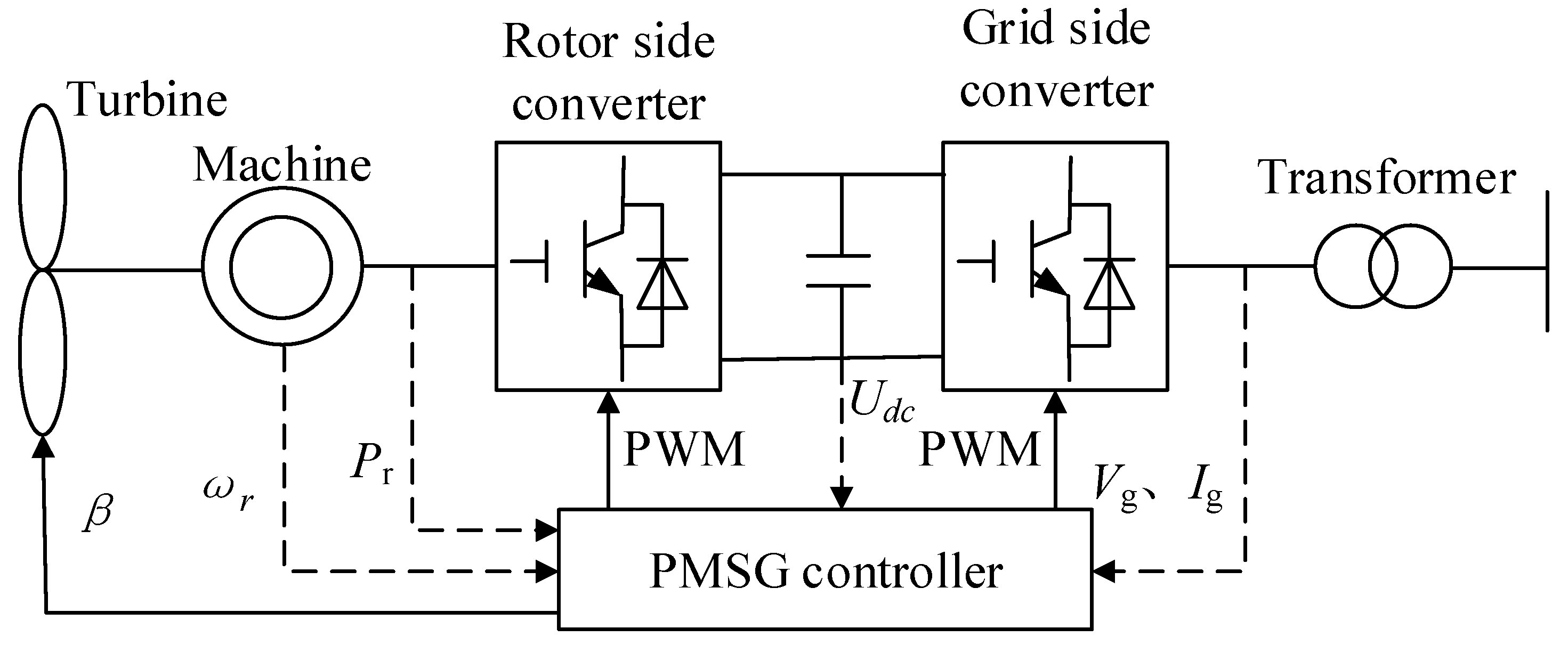
Figure 1 is a typical structure diagram of the PMSG model. It is made up of wind turbines, synchronous generators, and a corresponding converter controller. The parameters of a PMSG are shown in Table 1.
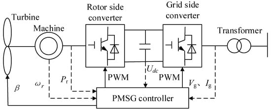
Figure 1.
Typical Structure of a PMSG.

Table 1.
Parameters of PMSG in this paper.
The mechanical power of the WTG is written as:
where is the mechanical power, is the wind speed, is the pitch-angle, is the utilization coefficient of wind energy, is the tip speed ratio, is the air density.
2.2. Conventional Frequency Control Scheme
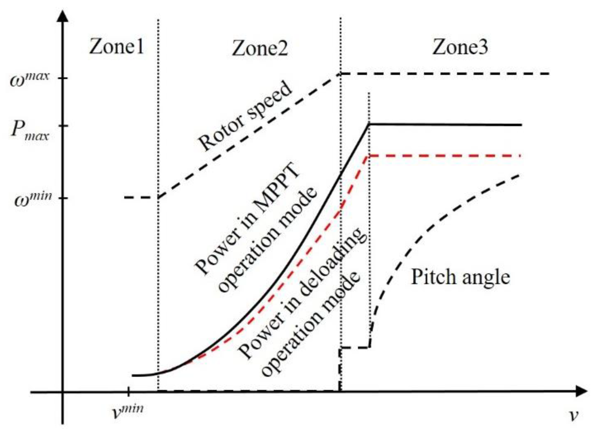
According to wind speed conditions, WTGs possess various operational modes [15]. The three zones of operation mode are divided as shown in Figure 2, namely, the constant power zone, the Maximum Power Point Tracking (MPPT) zone, and the constant speed zone.
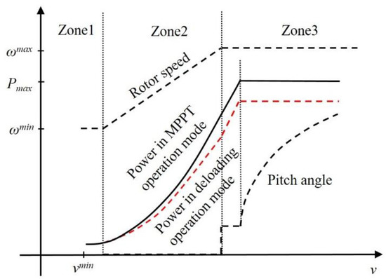
Figure 2.
Operation Curve of a PMSG.
Wind energy can be used to the maximum in the MPPT zone, and the rotor speed of the WTG can be controlled according to the wind speed to enable it to operate in the light of the maximum power curve. If the wind speed adds to the limit, the WTG enters the constant rotor speed zone and the power continues to increase. If the wind speed adds to the rated power, the WTG enters a constant power zone, and the pitch-angle is increased to keep the power constant. Under the various wind conditions, the control strategies adopted to allow the WTG to take part in the proposed frequency control are as follows: coordination with the over-speed deloading control and virtual inertia control in the MPPT zone, while the pitch-angle control and virtual inertia control are coordinated under constant speed zone or constant power zone.
2.2.1. Inertia and Over-Speed Coordinated Control
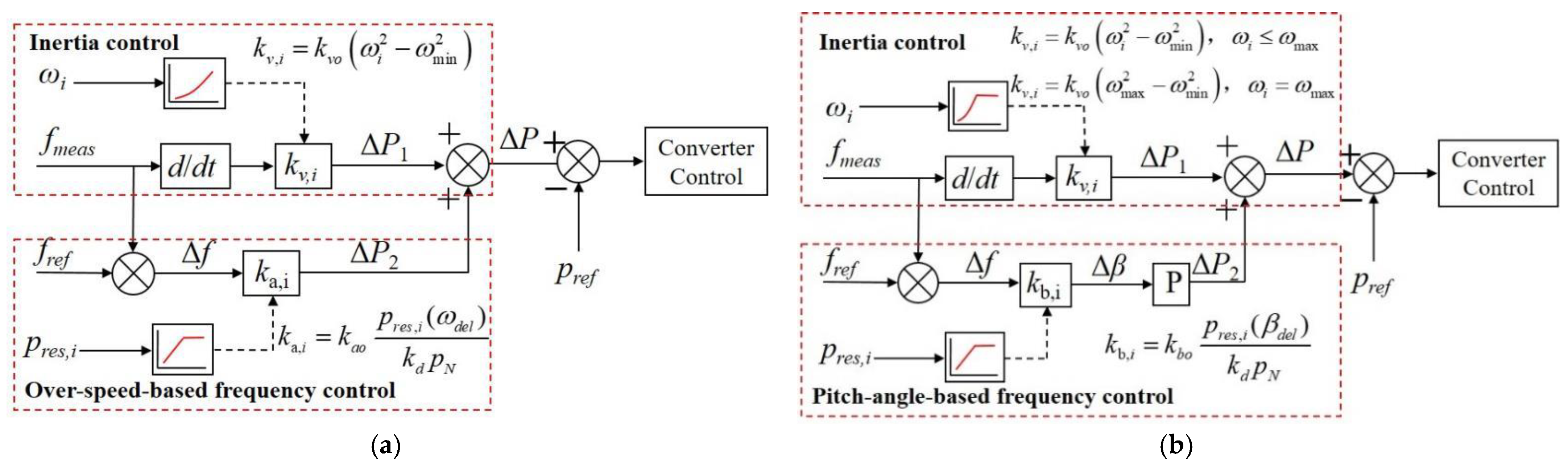
The conventional virtual inertial and over-speed-based deloading frequency control scheme is illustrated in Figure 3a, where is deloading level, and are additional power and control gain caused by virtual inertia control, respectively, and are additional power and control gain caused by over-speed deloading control, respectively, is the nominal frequency, is the observed frequency, is the frequency variable quantity.
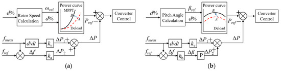
Figure 3.
Conventional frequency control scheme of a PMSG. (a) Inertia and over-speed coordinated control; (b) Inertia and pitch-angle coordinated control.
The additional power can be expressed as
2.2.2. Inertia and Pitch-Angle Coordinated Control
The conventional inertial and pitch-angle-based deloading frequency control scheme is illustrated in Figure 3b, where is control gain, is reference value, is the deviation.
The pitch-angle deviation and mechanical power can be expressed as
2.3. Wake Effect Model
Due to the influence of the upstream WTGs, the actual input wind speed will be larger than that of the downstream WTGs, and this phenomenon is called the wake effect. Since the Jensen model has simple features and high accuracy in describing WPP with flat terrain, as shown in Figure 4 [22], the Jensen model is used to describe the influence of wake effects on WPPs in the proposed strategy, and the actual wind speed of the downstream WTGs can be expressed as:
where vi is PMSGi wind speed, is wake-decaying constant, is axial induction factor, is ratio between the overlapping area and swept area of PMSGi, is swept area diameter of PMSGi, is radial distance, and n is the number of PMSGs.
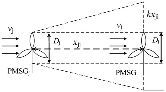
Figure 4.
Jensen wake effect model.
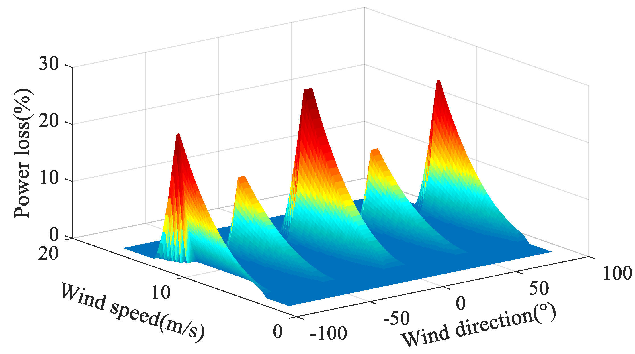
Figure 5 illustrates that a certain amount of wind energy loss will occur in the WPPs, which is affected by the wake effect, thus, the wake effect is an important factor when considering the frequency control of a WPP using reserve power.

Figure 5.
Impact of wake effect on wind energy loss in WPP.
2.4. Adaptive Frequency Control Scheme
In a WPP composed of several PMSGs, the effective wind speed of upstream WTGs is higher than that of downstream WTGs. Besides, it is regulated that all PMSGs operate at the same 10% deloading level due to prior disturbances occurring. Because PMSGs operate at different input wind speeds, they have different levels of actual active power, and thus have different levels of releasable reserve power. Therefore, the PMSGs operating in high wind speed regions contain more reserve power than those operating in low wind speed regions.
The proposed adaptive frequency control strategy aims to take full advantage of the releasable reserve power of WPPs within the allowable range. To achieve this goal, the proposed method differentiates the released reserve power, including rotor kinetic energy and deloading power of a PMSG, depending on its current reserve power level prior to an external disturbance. Specifically, the inertial control gain is regulated through the current rotor kinetic energy and the primary frequency control gain is regulated through the current deloading power.
2.4.1. Inertia and Over-Speed Coordinated Control
Figure 6a shows the proposed inertia and over-speed coordinated control scheme, the inertial control gain is adjusted depending on the current rotor kinetic energy which is a function of rotor speed, and releasable kinetic energy can be written as
where is the inertial time constant, and represent the rotor speed and the minimum speed of the -th PMSG.
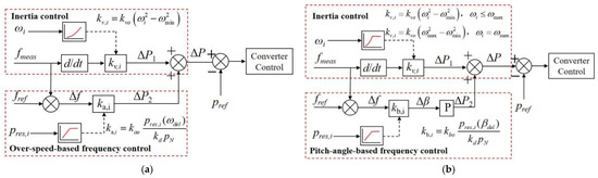
Figure 6.
Proposed adaptive frequency control scheme of a PMSG. (a) Inertia and over-speed coordinated control; (b) Inertia and pitch-angle coordinated control.
To achieve better inertial control performance, the changes of the PMSGi inertial control gain varies with the changes of the PMSGi releasable rotor kinetic energy, which can be expressed as
Thus, can be written as
where is a proportional constant.
On the other hand, the control gains is adjusted depending on the current deloading power which is a function of wind speed when the WTG is in the over-speed control condition. Meanwhile, the releasable deloading power of PMSGi can be written as
where d% is deloading level, represents the current maximum power of PMSGi, and are the operating active power and rotor speed after deloading, respectively.
To achieve better control performance of primary frequency under the over-speed control condition, the frequency control gain of PMSGi, is proportional to the releasable deloading power of PMSGi, is indicated as
Thus, is expressed as
where is a proportional constant.
2.4.2. Inertia and Over-Speed Coordinated Control
Figure 6b shows the proposed inertia and pitch-angle coordinated control scheme, although the inertial control gains is adjusted depending on the current rotor kinetic energy, if the rotor speed carries the maximum value point, the gain will be set to the maximum value and remain unchanged, thus can be obtained based on (9) in this frequency control scheme.
Besides, the deloading operation cannot be achieved through over-speed control under the condition of proposed control strategy, and the only the pitch-angle control method is able to adjust the power of PMSG. Thus, the releasable deloading power is written as
where is the regulation of pitch-angle, and the frequency control gain of PMSGi, , is proportional to the releasable deloading power of PMSGi, is written as
And is expressed as
where is a proportional constant.
Therefore, a larger inertial control gain and primary frequency control gain is designed for an upstream PMSG equipped with larger reserve power (rotor kinetic energy and deloading power), whereas a small inertial control gain and primary frequency control gain is designed for downstream PMSG equipped with smaller reserve power. Besides, if the rotor speed reaches the maximum rotor speed, the inertial control gain also has the maximum value, and the WPPs can obtain better primary frequency regulation performance and ensure stable operation.
3. Case Studies
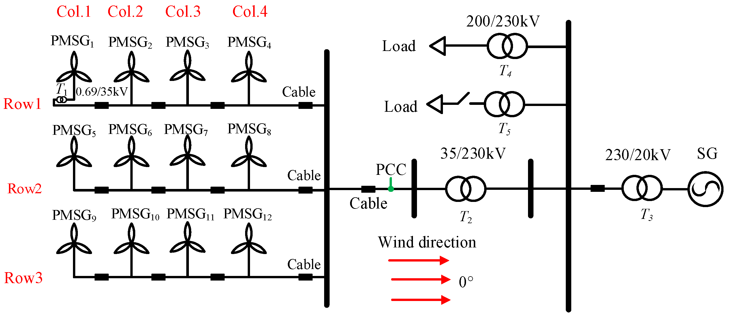
A test system is modeled by using a PSCAD/EMTDC simulator in this paper to study the effectiveness of the adaptive frequency control strategy. The model includes a conventional 100-MWsynchronous generator, 90-MWfix load, and a 36-MW PMSG-based WPP, and to simulate the disturbance of power imbalance, the system active load increases by 10% at 3 s, as shown in Figure 7.
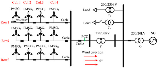
Figure 7.
Test system proposed in this paper.
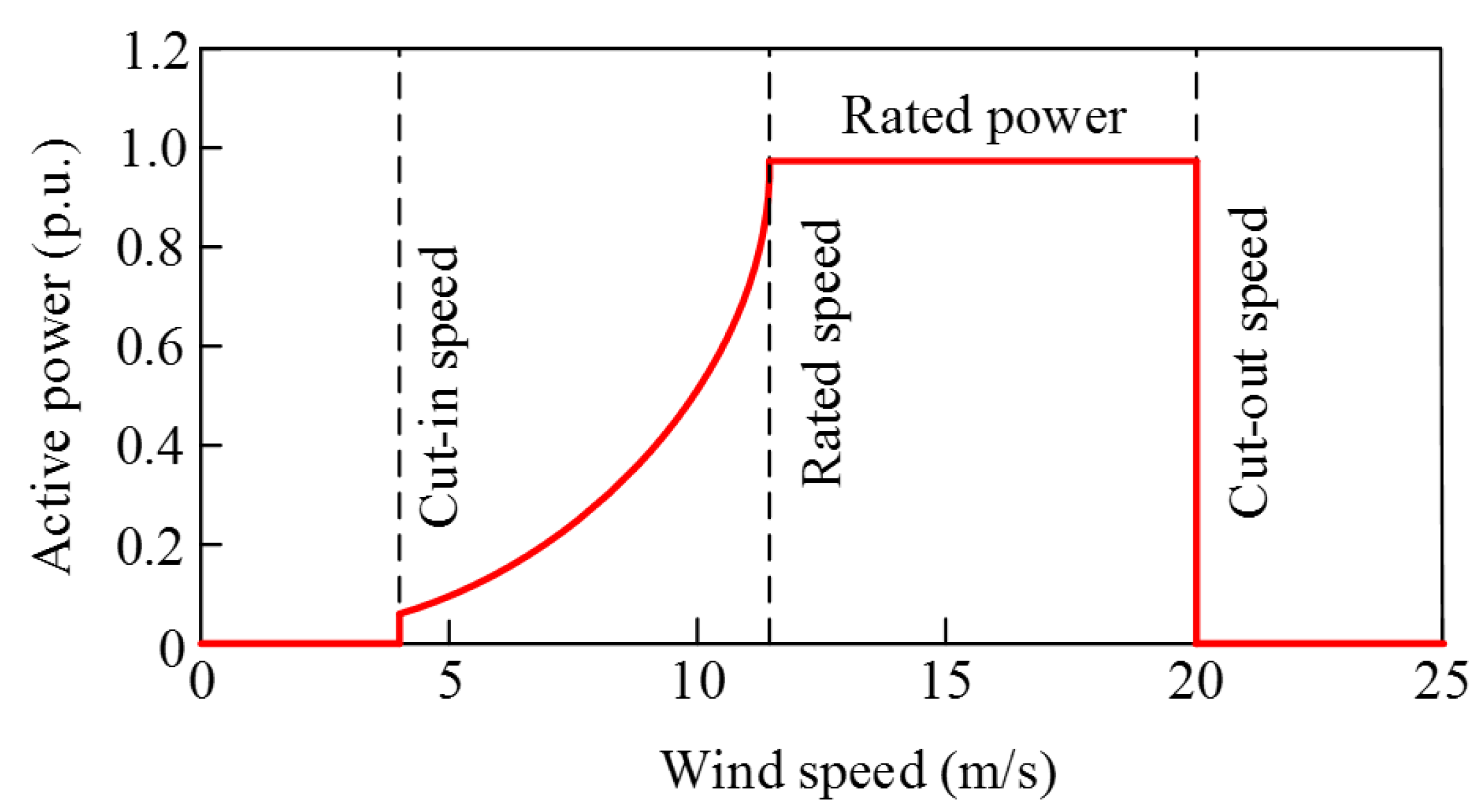
In the model system, the synchronous generator is a steam turbine generator, and it is equipped with a governor function. The WPP consists of 12 3-MVA PMSGs, the rated capacity and parameters of each PMSG in a WPP are the same, and the PMSG of each column and row is numbered separately to differentiate each PMSG. Figure 8 is the PMSG active power curve of this paper, the cut-in, cut-out wind, and rated speeds are 4 m/s, 20 m/s, and 11.4 m/s, respectively.

Figure 8.
Active power curve of a PMSG.
The choice of frequency control mode between pitch-angle control and over-speed control rests with the current input speed of the PMSG, and relevant inertial control capability or primary frequency control capability rests with the releasable reserve power. Thus, this section describes the effect of medium (10.5 m/s) and high (11.5 m/s) wind speeds with 0° during the period of frequency control performance. Two cases for two wind speeds and wind penetration levels have been implemented to prove the validity of the proposed strategy, relative to “fix gain scheme”, “only inertial control”, and “no frequency control”.
3.1. Case 1: Wind Speed of 10.5 m/s and Wind Penetration Level of 25.5%
In this case, the wind speed is 10.5 m/s, and the wind power penetration reaches 25.5%. The wind speed of PMSG1, PMSG5, and PMSG9 is 10.5 m/s, whereas, considering the wake effect, the wind speed of PMSG2, PMSG6, and PMSG10 is 9.94 m/s, the wind speed of PMSG2, PMSG6, and PMSG10 is 9.58 m/s, and the wind speed of PMSG4, PMSG8, and PMSG12 is 9.32 m/s, as shown in Table 2. Due to the fact that all PMSGs are in the MPPT, and the rotor speed does not reach the maximum, virtual inertia and over-speed deloading are coordinated for all PMSGs in this case.
Table 2.
Wind speed of Case 1 (m/s).
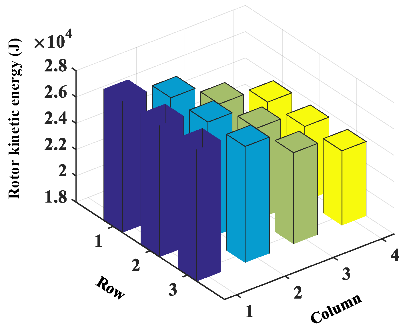
Due to the higher wind speed, the PMSGs in Col.1 have the largest rotor speed and active power, and thus the largest releasable reserve power (rotor kinetic energy and deloading power), whereas other downstream PMSGs have less releasable reserve power. The releasable rotor kinetic energy and deloading power of all PMSGs can be obtained by (8) and (10), as shown in Figure 9 and Figure 10, respectively. The inertial control gains obtained by using (10) and the primary frequency control gains based on over-speed control are illustrated in Table 3 and Table 4, and the inertial control gains and the primary frequency control gains set for upstream PMSGs are larger than those for downstream PMSGs. The reason is that when inertia and over-speed coordinated control is adopted, the kinetic energy and deloading power will be stored more for upstream PMSGs at the same deloaded level (10%).
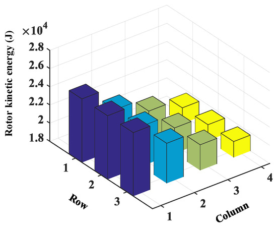
Figure 9.
Releasable rotor kinetic energy of all PMSGs in Case 1.
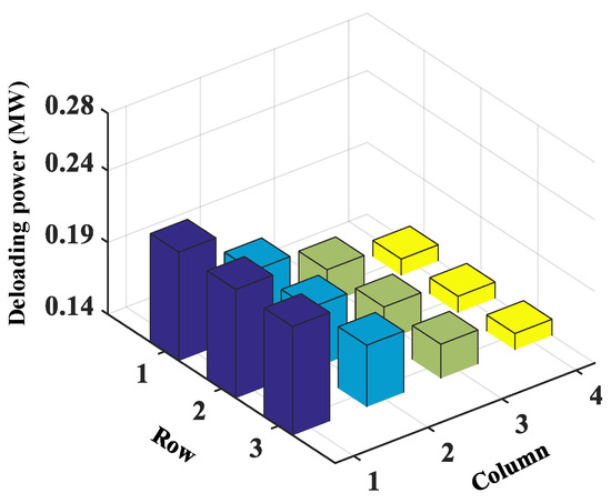
Figure 10.
Releasable deloading power of all PMSGs in Case 1.
Table 3.
Inertia control gain of Case 1.
Table 4.
Primary frequency control gain of Case 1.
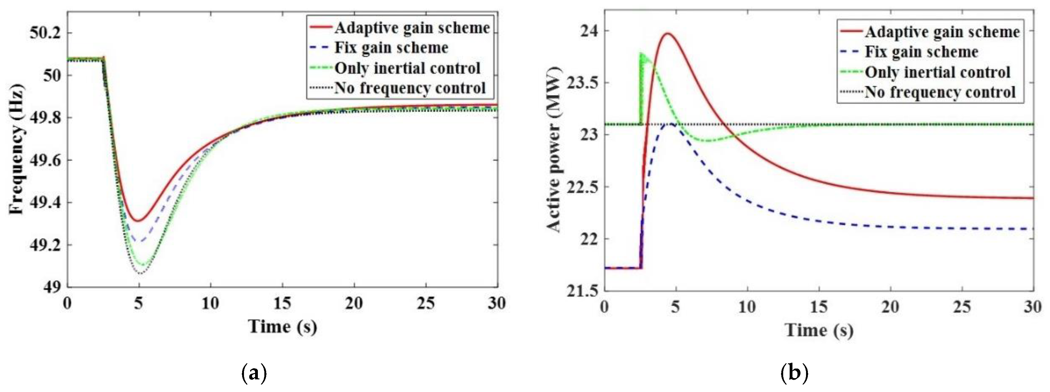
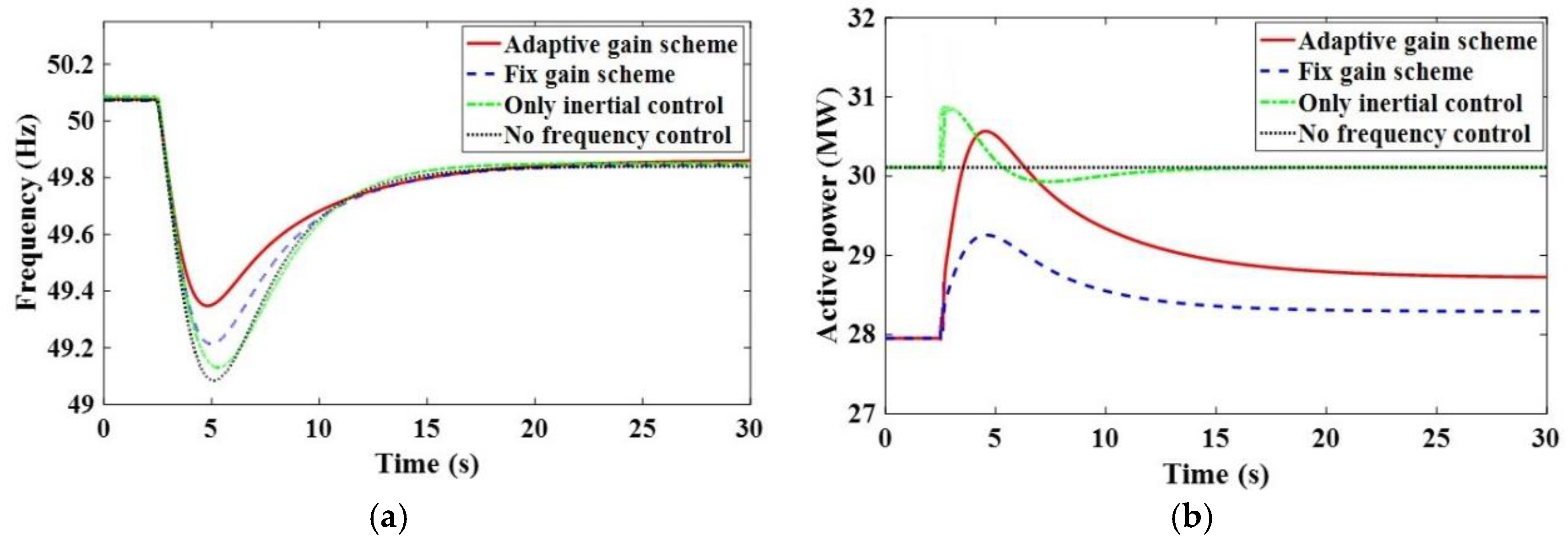
Figure 11 illustrates the frequency response performance of WPP for Case 1, and before the system frequency disturbance occurs, when the inertia and over-speed coordinated control modes are executed in the WPP, the PMSGs of the WPP are in the deloading mode, and the deloading level is 10%. When the “only inertial control” and “no frequency control” modes are executed in the WPP, the PMSGs are in maximum power mode. When the adaptive frequency control is adopted, if the system frequency disturbance occurs, the frequency nadir of the four schemes (i.e., adaptive gain scheme, fix gain scheme, only inertial control, and no frequency control) is 49.34 Hz, 49.23 Hz, 49.11 Hz, and 49.05 Hz, respectively. Besides, the traditional method is not as good as the proposed control strategy in terms of steady-state frequency. If the fix gain of inertial and primary frequency control is adopted, the frequency control performance is poor, and if only the inertial control is adopted and the deloading control is not considered, the frequency control performance would be even worse. Thus, a better frequency control performance could be obtained by using the proposed frequency control scheme, and if the system adopts the adaptive control gain, the optimal rotor kinetic energy and deloading reserve power could be used to contribute to the frequency regulation, as illustrated in Figure 11b.
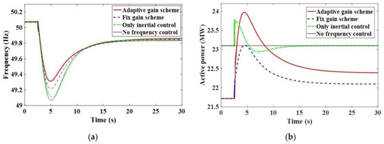
Figure 11.
Frequency response performance of wind power plant for Case 1. (a) system frequency; (b) active power of wind power plant.
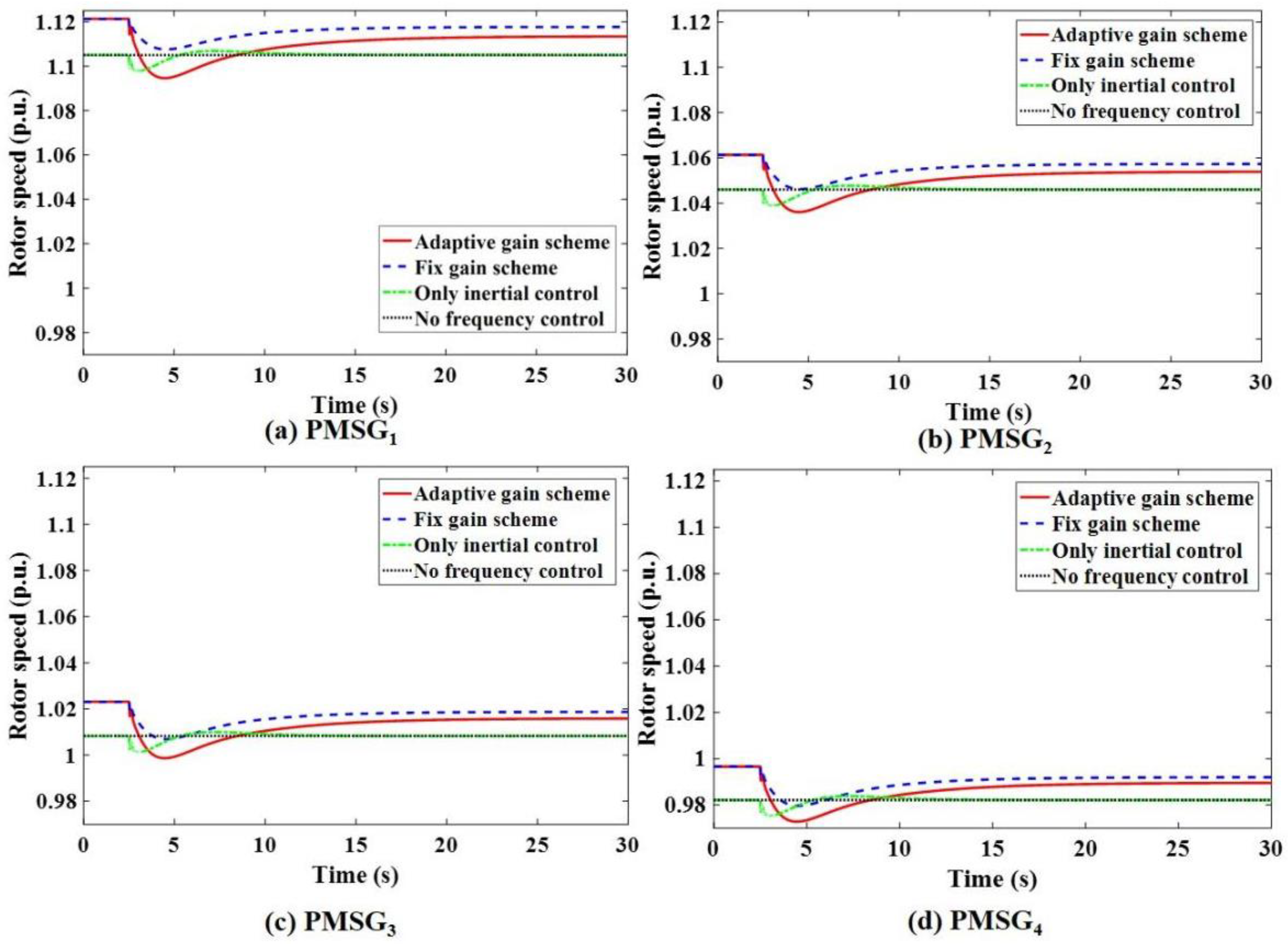
Figure 12 illustrates the rotor speed response of PMSG1, PMSG2, PMSG3, and PMSG4 for Case 1. It can be seen that compared with the “only inertial scheme”, the proposed frequency control scheme has a larger initial rotor speed due to deloading operation, and is therefore capable of storing more rotor kinetic energy. While compared with the “fix gain scheme”, although the initial rotor speed is the same, the recovery steady-state value after the disturbance is smaller for the proposed scheme, thus the WPPs release more rotor kinetic energy to participate in inertial control during the frequency, which is disturbed in the proposed frequency control scheme. In addition, the upstream PMSGs in a WPP have higher rotational speeds and more releasable rotor kinetic energy due to the wake effect, thus the gain of inertial control is set larger to fully release the stored rotor kinetic energy.
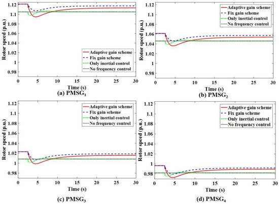
Figure 12.
Rotor speed response of the PMSGs for Case 1 under different control strategies. (a) rotor response of PMSG1; (b) rotor response of PMSG2; (c) rotor response of PMSG3; (d) rotor response of PMSG4.
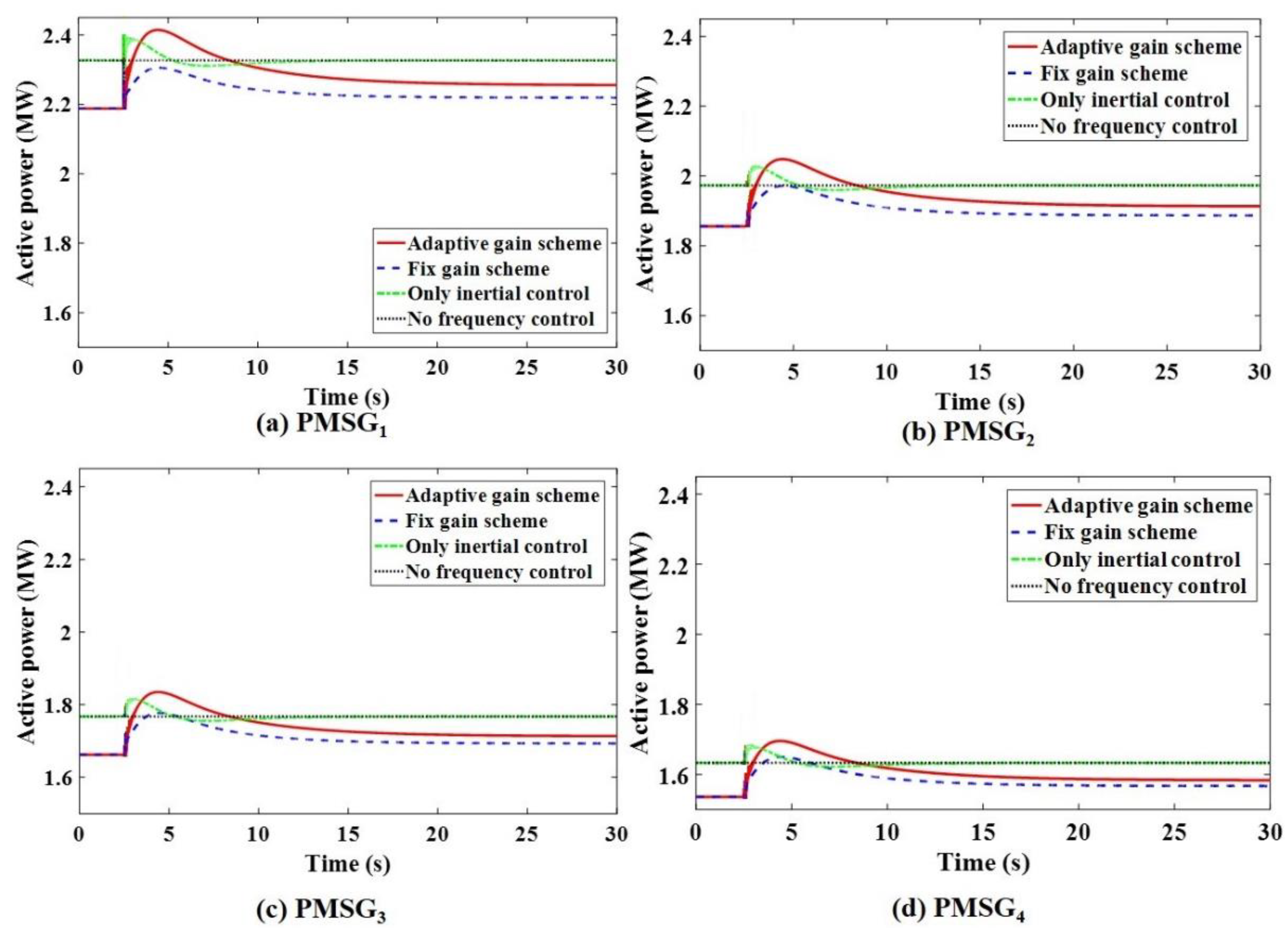
The power response of the PMSG1, PMSG2, PMSG3, and PMSG4 for Case 1 is illustrated in Figure 13. It can be seen that compared with the “only inertial scheme”, the proposed frequency control scheme has a lower initial operating active power due to deloading operation, and thus, has a releasable deloading power to contribute to primary frequency regulation. While compared with the “fix gain scheme”, although the initial active power (deloading level) is the same, the proposed frequency control scheme can not only release more rotor kinetic energy to participate in inertial control (Figure 13) but can also release more deloading reserve power to take part in primary frequency control when the system frequency is disturbed. In addition, the upstream PMSGs in a WPP have a larger initial operating active power and more releasable deloading reserve power, thus, the primary frequency control gain is larger than the stored rotor kinetic energy which is fully released, whereas the downstream PMSGs sets a smaller control gain.
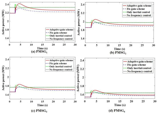
Figure 13.
Active power response of the PMSGs for Case 1 under different control strategies. (a) power response of PMSG1; (b) power response of PMSG2; (c) power response of PMSG3; (d) power response of PMSG4.
3.2. Case 2: Wind Speed of 11.5 m/s and Wind Penetration Level of 33.5%
The wind speed is 11.5 m/s, and wind penetration reaches 33.5% in Case 2. The wake effect should be considered in WPPs, and the corresponding wind speed of PMSGs are illustrated in Table 5. The PMSGs rotor speed in Col.1 (i.e., PMSG1, PMSG5, and PMSG9) and Col.2 (i.e., PMSG2, PMSG6, and PMSG10) are close to the maximum speed value, and it is impossible to achieve 10% deloading operation by over-speed control, thus virtual inertia and pitch-angle deloading are coordinated for these PMSGs, while the PMSGs in Col.3 (i.e., PMSG3, PMSG7, and PMSG11) and Col.4 (i.e., PMSG4, PMSG8, and PMSG12) still use virtual inertia and over-speed deloading control.
Table 5.
Wind speed of Case 2 (m/s).
Similar to Case 1, the upstream PMSGs have the largest rotor speed and active power, and thus, the largest releasable reserve power (rotor kinetic energy and deloading power) and control gains. Furthermore, the control gains are also proportional to the releasable reserve power, as mentioned in (9) and (16). In addition, the releasable rotor kinetic energy and deloading power of all PMSGs can be obtained by (13) and (14), which are larger than those in Case 1, as shown in Figure 14 and Figure 15, respectively. As a result, the inertial control gains and the primary frequency control gains are also larger than those of Case 1, as shown in Table 6 and Table 7, respectively. In Case 2, the primary frequency control method of PMSGs in Col.1 and Col.2 is based on pitch-angle control, and the corresponding gain is much larger than that based on over-speed control.
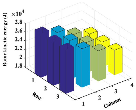
Figure 14.
Releasable rotor kinetic energy of all PMSGs in Case 2.
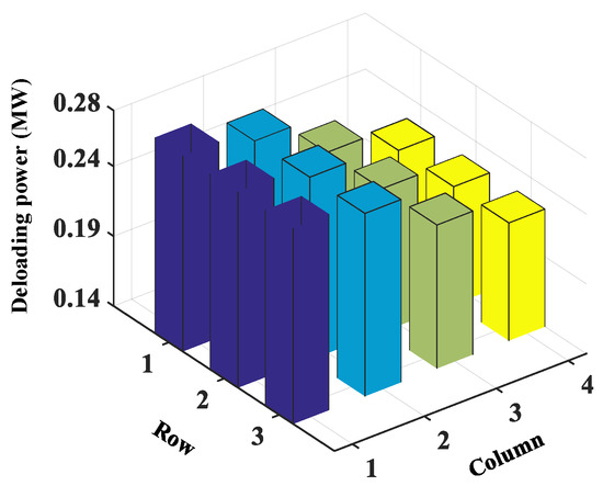
Figure 15.
Releasable deloading power of all PMSGs in Case 2.
Table 6.
Inertia gain of Case 2.
Table 7.
Primary frequency gain of Case 2.
The frequency response performance of WPP for Case 2 is shown in Figure 16. Similar to Case 1, the PMSGs of the WPP are in the deloading mode, and the deloading level is 10%. After the system frequency disturbance occurs, the frequency nadir of the four schemes (i.e., adaptive gain scheme, fix gain scheme, only inertial control, and no frequency control) is 49.38 Hz, 49.23 Hz, 49.15 Hz, and 49.05 Hz, respectively. Meanwhile, the traditional method is not as good as the proposed control strategy in terms of steady-state frequency. Due to the optimal rotor kinetic energy and deloading reserve power being sent out to take part in the frequency control, the proposed scheme has a better frequency control performance. The contrast between Figure 16b and Figure 11b shows that releasable and release reserve power of WPPs are larger because the wind speed has increased, thus the proposed scheme can contribute to promoting the frequency control performance in the higher wind speed conditions.
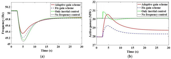
Figure 16.
Frequency response performance of wind power plant for Case 2. (a) system frequency; (b) active power of wind power plant.
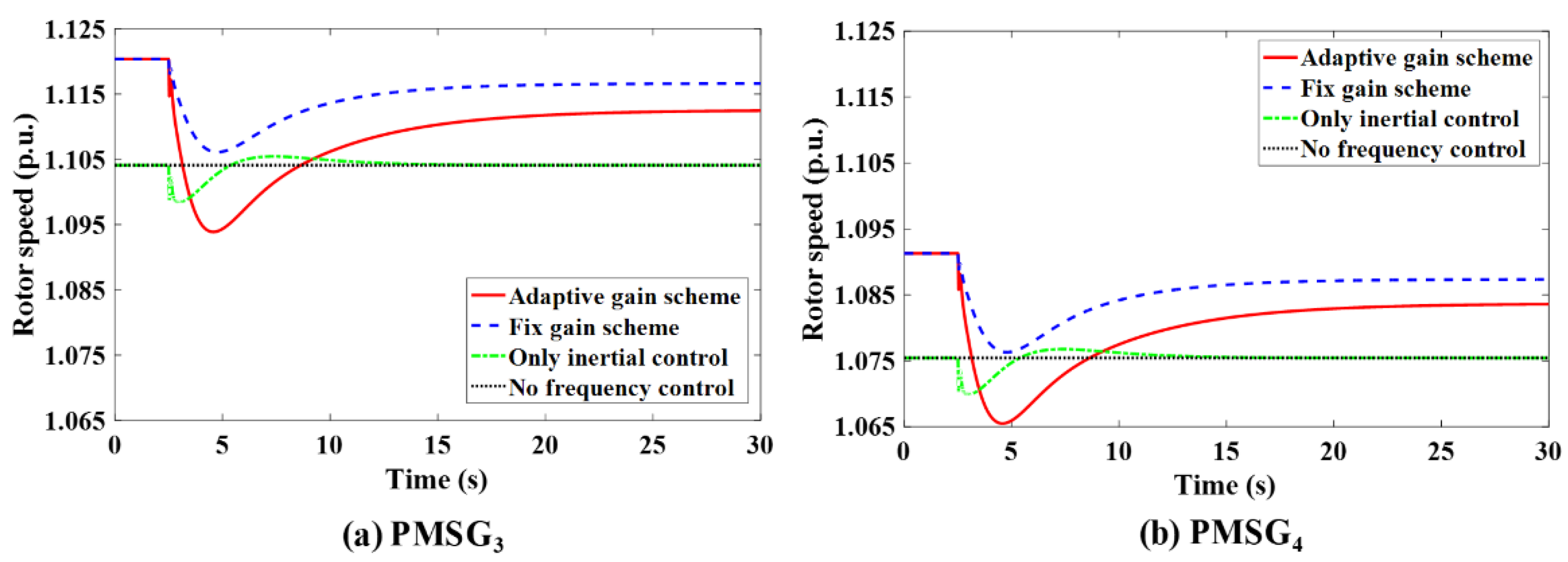
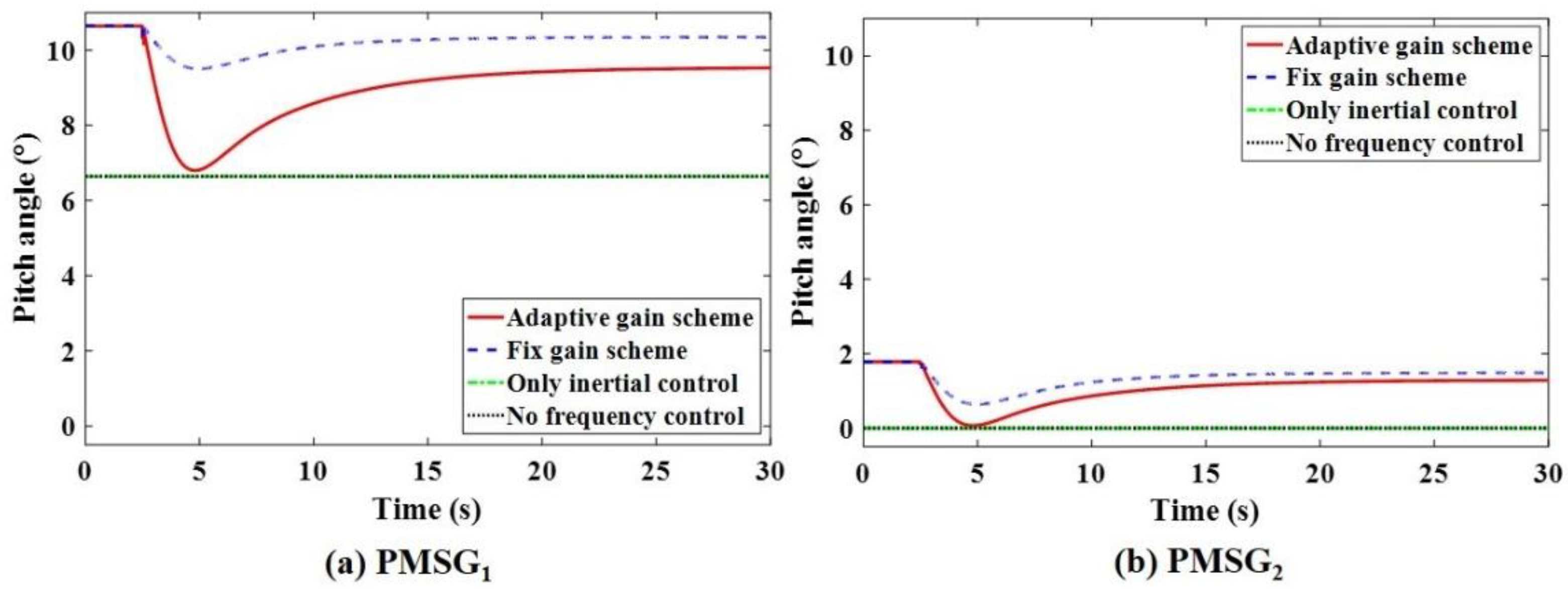
Since the PMSG1 and PMSG2 adopt pitch-angle control, while PMSG3 and PMSG4 adopt over-speed control, in this case, the rotor speed of PMSG1 and PMSG2 and the pitch-angle of PMSG3 and PMSG4 do not work during frequency disturbance. The corresponding speed response and pitch-angle response are shown in Figure 17 and Figure 18, respectively. Because the PMSG3 has higher rotational speeds and more releasable rotor kinetic energy and deloading power than PMSG4, the gain of inertial control and frequency control are set larger than PMSG4. Besides, PMSG1 has a higher pitch-angle and more releasable deloading power than PMSG2, thus the primary frequency control gain is designed larger, so it can fully release stored rotor kinetic energy.
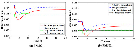
Figure 17.
Rotor speed response of the PMSGs for Case 2 under different control strategies. (a) rotor speed response of PMSG1; (b) rotor speed response of PMSG2.
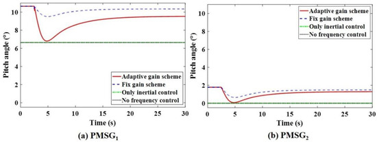
Figure 18.
Pitch-angle response of the PMSGs for Case 2 under different control strategies. (a) pitch-angle response of PMSG1; (b) pitch-angle response of PMSG2.
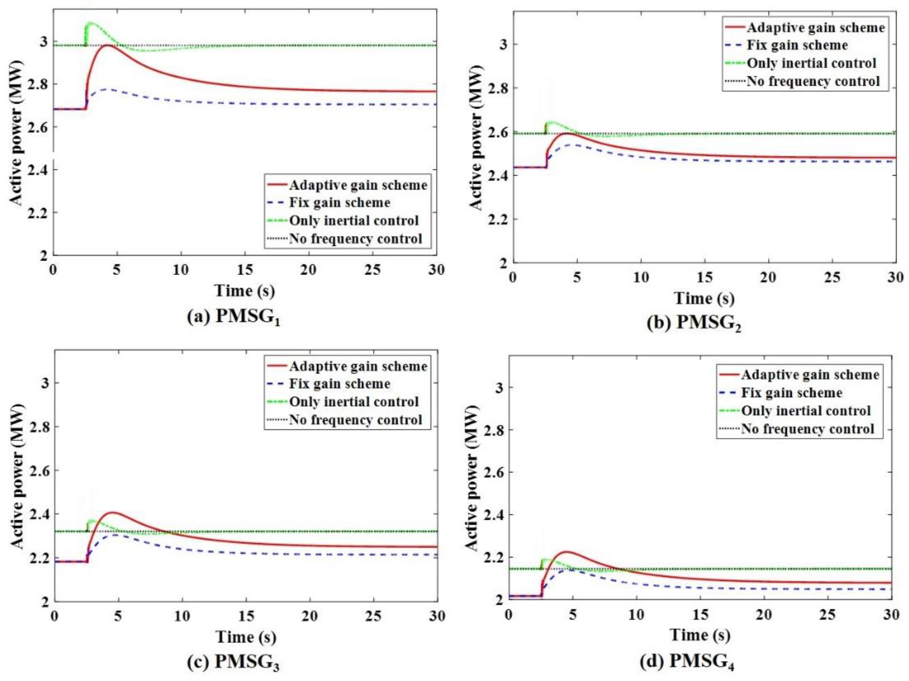
The active power response of PMSGs for Case 2 is shown in Figure 19. It also can be seen that each PMSG has more releasable reserve power than Case 1 due to the fact that wind speed has increased, and they can fully release the stored rotor kinetic energy and deloading power compared with the conventional fix gain control gain scheme and only the inertial control scheme. Therefore, the proposed frequency control scheme can achieve better frequency control performance.
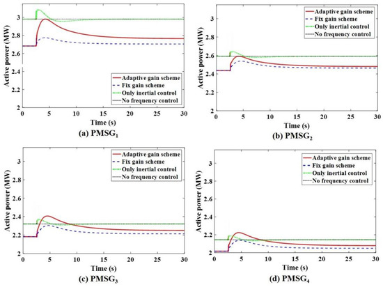
Figure 19.
Active power response of the PMSGs for Case 2 under different control strategies. (a) power response of PMSG1; (b) power response of PMSG2; (c) power response of PMSG3; (d) power response of PMSG4.
4. Conclusions
An adaptive frequency control strategy for a PMSG-based WPP considering releasable reserve power is proposed in this article, and according to the current releasable kinetic energy and deloading power which is closely related to rotor speed and actual active power, the inertial control gains and primary frequency control gains of PMSGs can be regulated adaptively. Therefore, a function formula of active power and rotor speed inertia gain and primary frequency modulation control gain is established, and the different inertial and frequency control gains are designed, which relates to the corresponding levels of releasable reserve power. Meanwhile, the PMSGs inertial and frequency control gains are regulated to the larger value because of the larger releasable reserve power developed by the potential frequency regulation, and the downstream PMSGs gains are regulated to a smaller value.
Finally, the case study analysis turns out that the proposed strategy is better than the traditional fix gain strategy or only inertial control scheme in frequency control. In addition, at the same deloading level, the proposed scheme can contribute more to promoting the performance of frequency control under the higher wind speed condition, especially in the large-scale wind power system. Thus, the stored reserve power of the PMSGs can be put to full use to promote the performance of frequency control while ensuring safe and stable operation.
Author Contributions
Conceptualization, J.D. and C.D.; methodology, J.D.; software, X.Z.; validation, C.D. and X.Z.; formal analysis, Y.T.; investigation, Y.T.; resources, X.Z.; data curation, C.D.; writing—original draft preparation, J.D. and C.D.; writing—review and editing, J.D.; visualization, C.D.; supervision, Y.T.; project administration, X.Z.; funding acquisition, J.D. All authors have read and agreed to the published version of the manuscript.
Funding
This research was funded by the Research Start-up Fund for Introduction of Talents (High-level Teachers), grant number NY220139.
Institutional Review Board Statement
Not applicable.
Informed Consent Statement
Not applicable.
Data Availability Statement
Not applicable.
Conflicts of Interest
The authors declare no conflict of interest.
Abbreviations
| WPP | Wind power plant |
| WTG | Wind turbine generators |
| PMSG | Permanent magnet synchronous generator |
| VSWTG | Variable speed wind turbine generators |
| DFIG | Doubly-fed induction generator |
| MPPT | Maximum Power Point Tracking |
References
- Global Wind Energy Outlook. Available online: www.gwec.net (accessed on 12 December 2019).
- Singh, N.K.; Koley, C.; Gope, S.; Dawn, S.; Ustun, T.S. An Economic Risk Analysis in Wind and Pumped Hydro Energy Storage Integrated Power System Using Meta-Heuristic Algorithm. Sustainability 2021, 13, 13542. [Google Scholar] [CrossRef]
- Feng, Y.; Lin, H.; Ho, S.L.; Yan, C.; Jian, H.; Dong, J.; Fang, S.; Huang, Y. Overview of wind power generation in China: Status and development. Renew. Sustain. Energy Rev. 2015, 50, 847–858. [Google Scholar] [CrossRef]
- Han, H.; Wu, C.; Wei, Z.; Zang, H.; Sun, G.; Sun, K.; Wei, T. A Two-Stage Cooperative Dispatch Model for Power Systems Considering Security and Source-Load Interaction. Sustainability 2021, 13, 13350. [Google Scholar] [CrossRef]
- Mcneil, M.A.; Feng, W.; Can, S.; Khanna, N.Z. Energy efficiency outlook in China’s urban buildings sector through 2030. Energy Policy 2016, 97, 532–539. [Google Scholar] [CrossRef] [Green Version]
- Muljadi, E.; Butterfield, C.P.; Parsons, B.; Ellis, A. Effect of Variable Speed Wind Turbine Generator on Stability of a Weak Grid. IEEE Trans. Energy Conver. 2007, 22, 29–36. [Google Scholar] [CrossRef]
- Gu, H.; Yan, R.; Saha, T.K. Minimum synchronous inertia requirement of renewable power systems. IEEE Trans. Power Syst. 2018, 33, 1533–1543. [Google Scholar] [CrossRef] [Green Version]
- Gil-González, W.; Montoya, O.D.; Grisales-Noreña, L.F.; Perea-Moreno, A.-J.; Hernandez-Escobedo, Q. Optimal Placement and Sizing of Wind Generators in AC Grids Considering Reactive Power Capability and Wind Speed Curves. Sustainability 2020, 12, 2983. [Google Scholar] [CrossRef] [Green Version]
- Tsili, M.; Papathanassiou, S. A review of grid code technical requirements for wind farms. IET Renew. Power Gener. 2009, 3, 308–332. [Google Scholar] [CrossRef]
- Wang, Z.; Wu, W. Coordinated control method for DFIG-based wind farm to provide primary frequency regulation service. IEEE Trans. Power Syst. 2017, 33, 2644–2659. [Google Scholar] [CrossRef]
- Ai, X.; Wu, Z.; Hu, J.; Li, Y.; Hou, P. Robust operation strategy enabling a combined wind/battery power plant for providing energy and frequency ancillary services. Int. J. Electr. Power Energy Syst. 2020, 118, 105736. [Google Scholar] [CrossRef]
- Yazdi, S.S.H.; Milimonfared, J.; Fathi, S.H.; Rouzbehi, K.; Rakhshani, E. Analytical modeling and inertia estimation of VSG-controlled Type 4 WTGs: Power system frequency response investigation. J. Electr. Power Energy Syst. 2019, 107, 446–461. [Google Scholar] [CrossRef]
- Arani, M.F.M.; El-Saadany, E.F. Implementing virtual inertia in DFIG-based wind power generation. IEEE Trans. Power Syst. 2012, 28, 1373–1384. [Google Scholar] [CrossRef]
- Li, P.; Hu, W.; Hu, R.; Huang, Q.; Yao, J.; Chen, Z. Strategy for wind power plant contribution to frequency control under variable wind speed. Renew. Energy 2019, 130, 1226–1236. [Google Scholar] [CrossRef]
- Gao, D.W.; Wu, Z.; Yan, W.; Zhang, H.G.; Yan, S.J.; Wang, X. Comprehensive frequency regulation scheme for permanent magnet synchronous generator-based wind turbine generation system. IET Renew. Power Gener. 2019, 13, 234–244. [Google Scholar] [CrossRef]
- Pahasa, J.; Ngamroo, I. Coordinated control of wind turbine blade pitch angle and PHEVs using MPCs for load frequency control of microgrid. IEEE Syst. J. 2014, 10, 97–105. [Google Scholar] [CrossRef]
- Van, T.L.; Nguyen, T.H.; Lee, D.C. Advanced pitch angle control based on fuzzy logic for variable-speed wind turbine systems. IEEE Trans. Energy Conver. 2015, 30, 578–587. [Google Scholar] [CrossRef]
- Zhang, Z.S.; Sun, Y.Z.; Lin, J.; Li, G.J. Coordinated frequency regulation by doubly fed induction generator-based wind power plants. IET Renew. Power Gener. 2012, 6, 38–47. [Google Scholar] [CrossRef]
- Zhao, J.J.; Lyu, X.; Fu, Y.; Hu, X.G.; Li, F.X. Coordinated Microgrid Frequency Regulation Based on DFIG Variable Coefficient Using Virtual Inertia and Primary Frequency Control. IEEE Trans. Energy Conver. 2016, 31, 833–845. [Google Scholar] [CrossRef]
- Tang, X.; Yin, M.; Shen, C.; Xu, Y.; Dong, Z.Y.; Zou, Y. Active power control of wind turbine generators via coordinated rotor speed and pitch angle regulation. IEEE Trans. Sustain. Energy 2018, 10, 822–832. [Google Scholar] [CrossRef]
- Pradhan, C.; Bhende, C.N. Adaptive deloading of stand-alone wind farm for primary frequency control. Energy Syst. 2015, 6, 109–127. [Google Scholar] [CrossRef]
- Ahmadyar, A.S.; Verbič, G. Coordinated operation strategy of wind farms for frequency control by exploring wake interaction. IEEE Trans. Sustain. Energy 2016, 8, 230–238. [Google Scholar] [CrossRef]
- Ma, S.; Geng, H.; Yang, G.; Pal, B.C. Clustering-based coordinated control of large-scale wind farm for power system frequency support. IEEE Trans. Sustain. Energy 2018, 9, 1555–1564. [Google Scholar] [CrossRef]


Publisher’s Note: MDPI stays neutral with regard to jurisdictional claims in published maps and institutional affiliations. |
© 2022 by the authors. Licensee MDPI, Basel, Switzerland. This article is an open access article distributed under the terms and conditions of the Creative Commons Attribution (CC BY) license (https://creativecommons.org/licenses/by/4.0/).