Article

Development of a Bio-Digital Interface Powered by Microbial Fuel Cells

1
Bristol BioEnergy Centre (BBiC), Bristol Robotics Laboratory, T Block, Frenchay Campus, University of the West of England, Bristol BS16 1QY, UK
2
Translating Nature, 11 Palm Bay Avenue, Margate CT9 3DH, UK
3
Department of Architecture, Campus Sint-Lucas, KU Leuven, Hoogstraat 51, B-9000 Ghent/Paleizenstraat 65, B-1030 Brussels, Belgium
4
Water & Environmental Engineering Group, School of Engineering, Bolderwood Campus, University of Southampton, Burgess Street, Southampton SO16 7QF, UK
*
Authors to whom correspondence should be addressed.
Sustainability 2022, 14(3), 1735; https://doi.org/10.3390/su14031735
Submission received: 13 December 2021 / Revised: 7 January 2022 / Accepted: 8 January 2022 / Published: 2 February 2022

Abstract

:
This paper reports the first relatable bio-digital interface powered by microbial fuel cells (MFCs) that was developed to inform the public and introduce the concept of using live microbes as waste processors within our homes and cities. An innovative design for the MFC and peripherals system was built as a digital data generator and bioreactor, with a custom-built energy-harvesting controller that was connected to the system to enable efficient system operation using adaptive dynamic cell reconfiguration and transmit data for the bio-digital interface. This system has accomplished multiple (parallel) tasks such as electricity generation, wastewater treatment and autonomous operation. Moreover, the controller demonstrated that microbial behaviour and consequent system operation can benefit from smart algorithms. In addition to these technical achievements, the bio-digital interface is a site for the production of digital art that aims to gain acceptance from a wider-interest community and potential audiences by showcasing the capabilities of living microorganisms in the context of green technologies.

1. Introduction

Although the first discovery of microbial electricity generation was made over 100 years ago [1], attention towards microbial fuel cell (MFC) technology has only begun to grow fairly recently (1990s), and it is still unfamiliar to the public. Whether or not future developers have encountered a technology, either directly or indirectly, this is crucial in its development. In contrast to existing large-scale sewage treatment facilities, MFCs enable medium/small-scale, decentralised, remote, on-site sewage treatment, as well as energy generation [2,3]. While there are still several technical challenges to overcome to achieve full commercialisation, such as the relatively low power density and high initial investment costs [4], additional challenges that cannot be overlooked include the perception, public acceptability and usability of the technology, which do not have technological solutions and, therefore, require different approaches.
Microbial fuel cell technology is being developed for real-world implementation as a commercially viable product, with demonstrations in various settings such as public science events, music festivals [5] and field trials [6], as an essential tool for technology evaluation. One of the previous study investigated user perception of the technology where everyday use enabled end users to understand its benefits [7]. Such studies have revealed that MFC technology could be highly acceptable and help tackle sanitation issues by providing not only electricity but also accompanying benefits such as feeling safe and improving toilet cleanliness. Despite very positive feedback received so far, the broader uptake of MFC technology into our daily lives requires further work. For example, although there is a growing social consensus on the need for wastewater reuse, the biggest challenge lies in changing the stakeholders’ perception of the water cycle more than technological developments [8,9]. Therefore, in order to develop and disseminate a particular technology, efforts must be made in many respects, such as understanding the need, technical context of the solution and cultural acceptance/resistance to this.
The goal of this project is to develop a bio-digital interface that encompasses technological advancements in an art installation, to better articulate how the technology works and encourage public engagement through curiosity that assists its progress towards the market. By developing an attractive interface that enables people and microbes to interact, enhances the user experience and increases the probability of technology uptake. This approach may further result in the same system being utilised as an educational tool or become part of the emerging market of ecohomes [10]. Following the successful completion of the Living Architecture project [11], which demonstrated a selectively programmable bioreactor wall for future living spaces, development of the first relatable bio-digital interface powered by MFCs was set to inspire the public and to introduce the concept of using live microbes as processors of waste within our homes and cities. This ‘sociable’ interface is a first-generation bio-digital hardware and user experience that translates microbial activity into meaningful encounters with human audiences, establishing a trans-species communications platform. Beginning with an electronic interface powered by MFCs, it extracts data from sensors, which is translated into a lively, communicable display that is showcased in a range of social contexts—from art galleries to exhibition spaces and festivals. From a scientific perspective, the following objectives were pursued: (i) develop an innovative MFC design capable of generating sufficient levels of power; (ii) develop an energy-efficient, multi-functional electronic controller; (iii) better understand microbial behaviour in functioning MFCs when subjected to external stimuli from the electronic controller.

2. Materials and Methods

2.1. System Design, Operation and Performance Measurement

For this work, a total of 15 MFC units were built and placed in five cascade groups of three MFCs. The bioreactor chassis was 3D printed in ABS (acrylonitrile butadiene styrene) with dimensions of 193 × 100 × 80 mm (W × H × D). Each MFC bioreactor consists of two anode chambers and two cathode chambers alternately located. This is to increase the contact area between the anode and cathode chambers within the volume of a given individual MFC unit; the two anodes and two cathodes of each MFC were connected in parallel. Each chamber holds approximately 100 mL and 120 mL volumes of anolyte and catholyte, respectively. The anode electrodes were made from plain carbon veil (20 g/m2 carbon loading, PRF Composite Materials, Poole, Dorset, UK) modified with activated carbon ink [12]. Each anode electrode had a macro surface area of 1,350 cm2 (30 × 45 cm). A U-shaped cathode made of thermally compressed activated carbon on stainless steel mesh [13] was placed inside each cathode chamber in contact with ceramic membranes. The size of the cathode (macro surface area) was 68 cm2 (17 × 4 cm). Custom-made ceramic membrane sheets (65 × 85 mm each, thickness of 3 mm) [14] were placed between the anode and cathode chambers. The MFCs were designed to be gravity fed (the effluent of the MFC above becomes the influent of the MFC below) in order to reduce the energy input requirements. The flow of both anolyte and catholyte of the MFC system is described in Figure 1.
MFC anodes were inoculated with activated sludge collected from a local sewage treatment plant (Wessex Water, Saltford, UK), after being cultivated for 24 h in artificial urine medium (AUM). AUM was also used as feedstock and supplied to the system at various flow rates ranging between 1.5 L/d and 16.0 L/d. The composition of feedstock was modified from a previous study [15], containing the following: 2.5 g/L peptone, 0.5 g/L yeast extract, 5 g/L urea, 5.2 g/L sodium chloride, 1.4 g/L sodium sulphate, 0.95 g/L potassium dihydrogen phosphate, 1.2 g/L di-potassium hydrogen phosphate. A day after inoculation, a fixed external resistance of 200 Ω was connected to each MFC. The value of external resistance was gradually decreased to 100 Ω before being connected to a bespoke electronic controller on day 14.
The voltage output levels of 15 MFCs in volts (V) were initially monitored against time using a data logger (34972A DAQ unit, Agilent Technologies, Santa Clara, CA, USA) every 5 min. Once the aforementioned electronic controller was connected to the system, MFC power performance, including voltage, current, power and information of electrical configurations, was monitored by the controller in different time intervals. Power density (PD) of an MFC unit or of the entire MFC system was normalised by the anolyte volume of 200 mL (per unit) or 3 L (for the whole system). In order to verify an individual MFC performance, periodic polarisation experiments were performed. For this, MFCs were left open circuit for at least 3 h before the run to reach stable open circuit voltages (OCVs). Then, various external resistances ranging from 1.2 kΩ to 4 Ω were loaded every 5 min and the potential between the anode and cathode was recorded every 30 s. For measuring chemical oxygen demand (COD), water samples were filtered using 0.45 µm syringe filters and then immediately analysed using a COD test kit (COD test tubes, Camlab, Cambridge, UK).

2.2. Electrical Infrastructure

A bespoke system, consisting of the electronic control system (ECS), power connections, external sensors, external actuators such as pumps and LEDs and a data-communication link, was developed to interface the MFC system located in the laboratory with the users’ virtual experience. This infrastructure was autonomously harvesting electrical energy generated from the MFC array to measure, filter and collect the parameters of interest used for the live animation on the web user interface and transmit these collected data over a secure link to the user interface application; this app allows the user to visualise the data in a truly unique fashion (Figure 2).
The electrical infrastructure system is broken down into a number of functional subsystems, including energy harvesting, cell management (dynamic reconfiguration), self-regulation, measurement, data logging and transmission. The autonomous self-regulating system was designed, based on the EcoBot principle [16,17], to mimic a living organism in which actions are governed by energy availability (Figure 3).
The ECS electronics consist of two microcontroller units (MCUs), which are software driven and thus require electronic firmware. The firmware consists of device drivers, diagnostics and applications. The first MCU consists of a power management module, which operates and manages the energy harvester, and other power-related functions. It operates in low-power (sleep) mode and is awakened periodically by a timer. It operates the main power switches that supply the ECS and monitors bulk capacitor voltage and bus power. The second MCU is responsible for all the applications and communications. This MCU is user programmable, and applications can be uploaded via a universal serial bus (USB) link. The applications consist of cell reconfiguration, measurement, data logging, external sensors and other external devices such as pumps and LEDs.

2.3. Bio-Digital Interface

The interaction infrastructure design aims to capture meaningful data from the MFC system and visualise it appropriately to inform the user experience. The interactive live-streamed animations and live system information are either measured or processed parameter data such as individual cell voltage, cell current, cell power, stack current, stack power, ambient temperature, humidity, rate of change of power, ECS internal voltage, bulk capacitor store voltage, cell configuration information and LED actuation. Data transmission infrastructure enabled the MFC system to be used for the user experience, which involved transferring data from the ECS to the user experience server. This was accomplished via the periodic publication of data by the ECS to a single board computer attached to the ECS, which in turn executes a program to save sensor data to a local MySQL (My Structured Query Language) based database, and via encrypted SSH (Secure Shell) to a remote MySQL database on the external server. The SSH connection is secured with a public/private RSA (Rivest–Shamir–Adleman) key pair, with the private key living on the single board computer and the public key on the server. Once the connection is made, an application saves the data on the server.
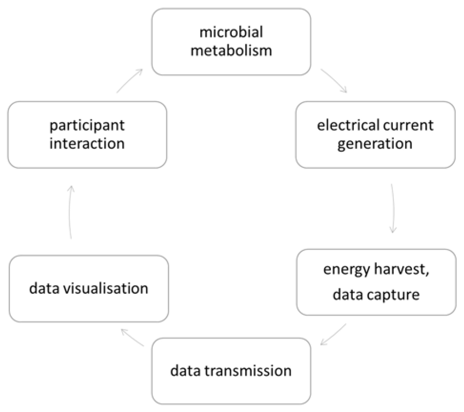
Figure 4 shows the established responsive feedback loop between microbial action mediated through the MFC array that generates live data for the user experience, which the participant responds to by interacting with the microbes through animations shaped by live data and, in doing so, generates new data. Participants can choose from several actions, such as feeding the microbes, changing both the ambient and fluid temperature (warming or cooling) and changing the supply rate of feedstock to the microbes. The data from these interactions will feed forward into the live data animations, so that a broader community of participants can see the online events unfolding.

3. Results and Discussion

3.1. Individual MFC Performance

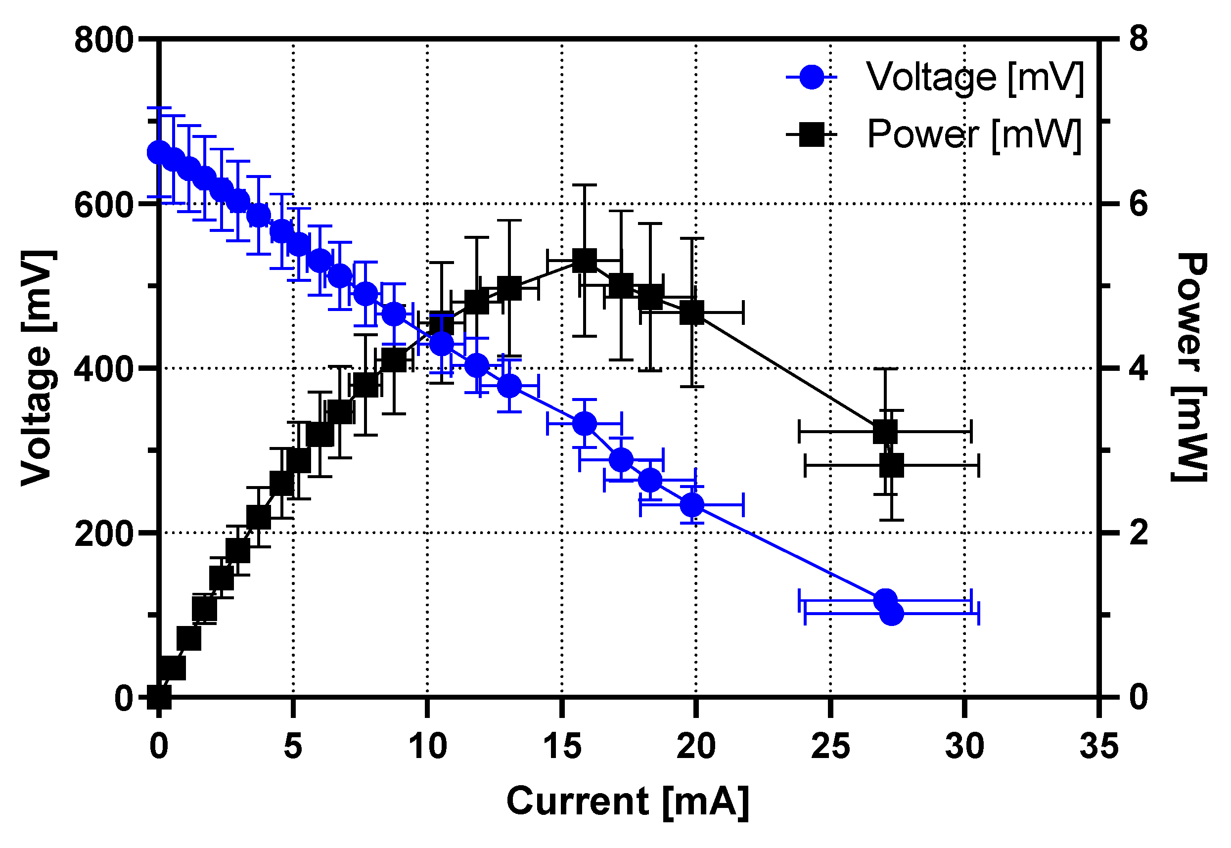
Figure 5 shows the average power-generating performance of the 15 MFCs. The polarisation sweep was performed on day 20, when the cells were assumed to have reached a quasi-steady state. The average open circuit (OCV) value was 663 ± 55 mV and the maximum power output was 5.3 ± 0.9 mW (power density: 26.5 W/m3) on average, reaching up to 6.5 mW (32.5 W/m3).
During the same period, when the MFCs were running individually without being electrically connected through the ECS, the organic content of the feedstock measured in COD decreased by 18.9 ± 2.3, 27.4 ± 7.5 and 19.6 ± 3.9% in the top, middle and bottom rows of the MFCs, respectively. Although the amount of organic consumption differs depending on the location within a cascade, there was no significant difference in the maximum power output. This means that this flow rate (4.0 L/d) and organic concentration (COD of 3.45 mg/L) were sufficient to feed the last cell of each cascade following a sequential cascade treatment.
Several strategies have been established to increase the wastewater treatment efficiency, such as increasing the hydraulic retention time (HRT) by reducing the flow rate or enlarging the cell footprint [18], increasing the operating temperature [19] or increasing the external load [20]. Among these, increased HRT and operating temperature can lead to higher operating costs unless properly optimised. External load changes can be relatively simple to apply at no significant additional cost. Several research groups have reported that appropriately changing the value of the external resistance over a certain period of time, can increase the power output [21,22], as it is related to the microbial metabolic rate. Dynamic reconfiguration, using smart algorithms, is therefore worth pursuing as an efficient MFC operation strategy and is discussed in more detail in the next section.
The MFC reactor design used in this study employed a partial open-to-air cathode, in which 1/2 of the cathode and 1/3 of the membrane (on the cathode side) are submerged in the catholyte. The cathode chamber was initially empty, and catholyte began to accumulate as the MFC started operating. A complete air cathode is a popular choice in the field due to its design simplicity, smaller footprint and lower material cost, but precipitation of salts on the cathode electrode has been reported [23,24], which can be problematic. However, in this design, the ceramic membrane can remain wet, and no significant reduction in power output was observed during the one-year operation period.

3.2. MFC Stack Performance as a Digital Data Generator

The ECS (electronic control system) is an energy management unit consisting of an energy harvester, power management unit and a mechanism to reconfigure cell connection topologies (cell reconfiguration). During operation, the ECS attempts to harvest the maximum energy while sustaining the MFCs for long-term operation. This is useful as the loading of the harvester on the MFC stack dynamically changes depending on the state of the MFCs, based on feedback [25].
The electrical connection of the 15 MFC units was dynamically changed by the ECS to the following four topologies: all in parallel (15P), all in series (15S), five cells in parallel with the three groups in series (5P3S) and three cells in parallel within the five groups in series (3P5S). Initially, the MFC stack operated at a fixed setting of 15P during inoculation and maturation. An ‘adaptive gain’ (AG) method, based on dynamic gain allocation and the rate of change of power with voltage clamping in the range of 350~450 mV, was used during subsequent operation. The energy harvester acted as a pseudo-time-varying non-linear voltage-controlled current sink with a voltage range of 0.15~5 V and a max sink current of 70 mA.
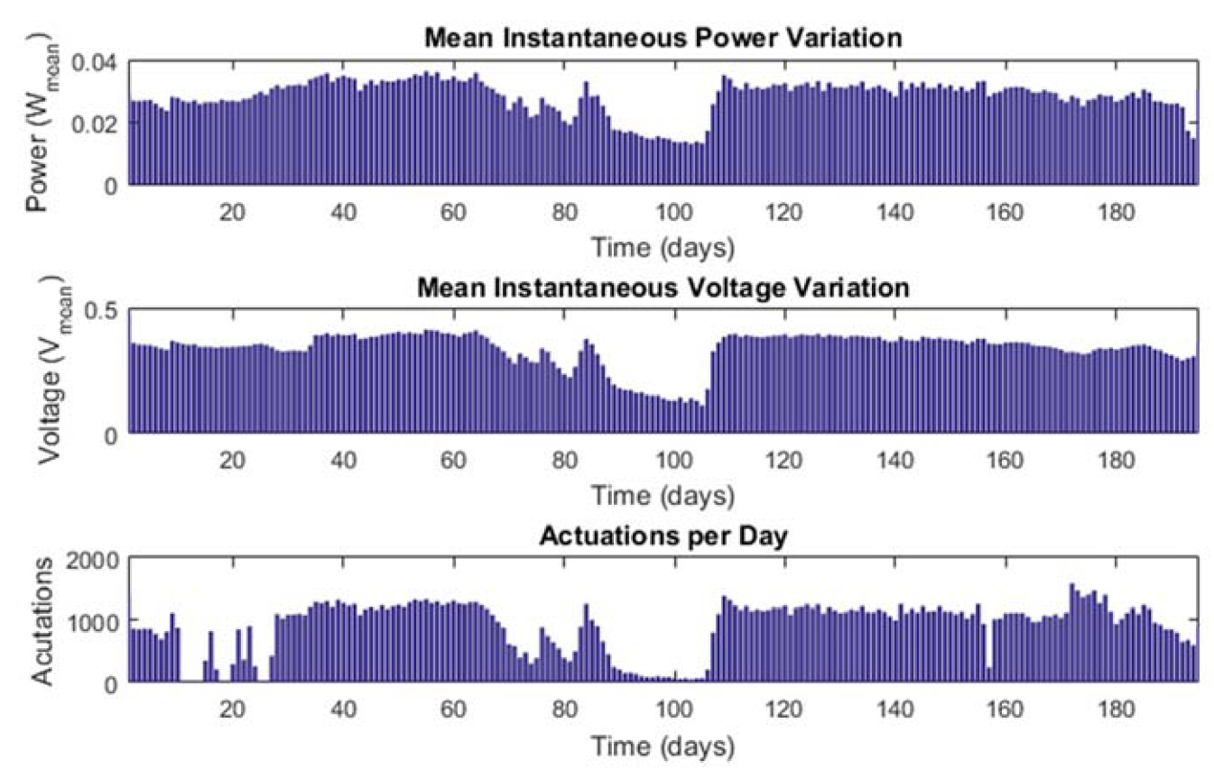
The performance of the energy harvester and MFC stack was evaluated by observation of the mean instantaneous power, mean instantaneous voltage and by the number of actuations per day (Figure 6). The ECS checked energy levels approximately every two minutes and performed data logging and/or actuation depending on the energy acquisition. During the first 200 days of operation, the system harvested a mean instantaneous power of 28.36 ± 5.5 mW, with a minimum of 13.02 mW and a maximum of 36.34 mW; this was at a mean voltage of 339.63 ± 70.75 mV with a minimum voltage of 110.13 mV and a maximum voltage of 477.24 mV at each check. An LED configuration acted as the demonstrable actuation of the 15-MFC system (in addition to all the energy management and data communication) with a 20-s actuation/display; the mean number of 20-s actuations per day was 905, with a minimum of 6 and a maximum of 1578. Overall, the MFC system showed a consistently stable performance, except during days 90–105 when the feed rate was reduced to a minimum (0.7 L/d) due to the Christmas break. Figure 7 shows the MFC system installed in the laboratory actuating the LED lights (top left).
By utilising a cell reconfiguration mechanism, the system maintains the microbial activity within the MFCs as well as the power output at optimum levels [26,27]. External electrical loading can change the internal impedance and the impedance is varied by changing the connection topology. Here, we create four dynamic impedances which also have an effect on the loading of MFCs, drawing optimum levels of current depending on state of performance. By employing dynamic cell reconfiguration, the MFCs are maintained such that they increase in power output over time until a steady state is reached.
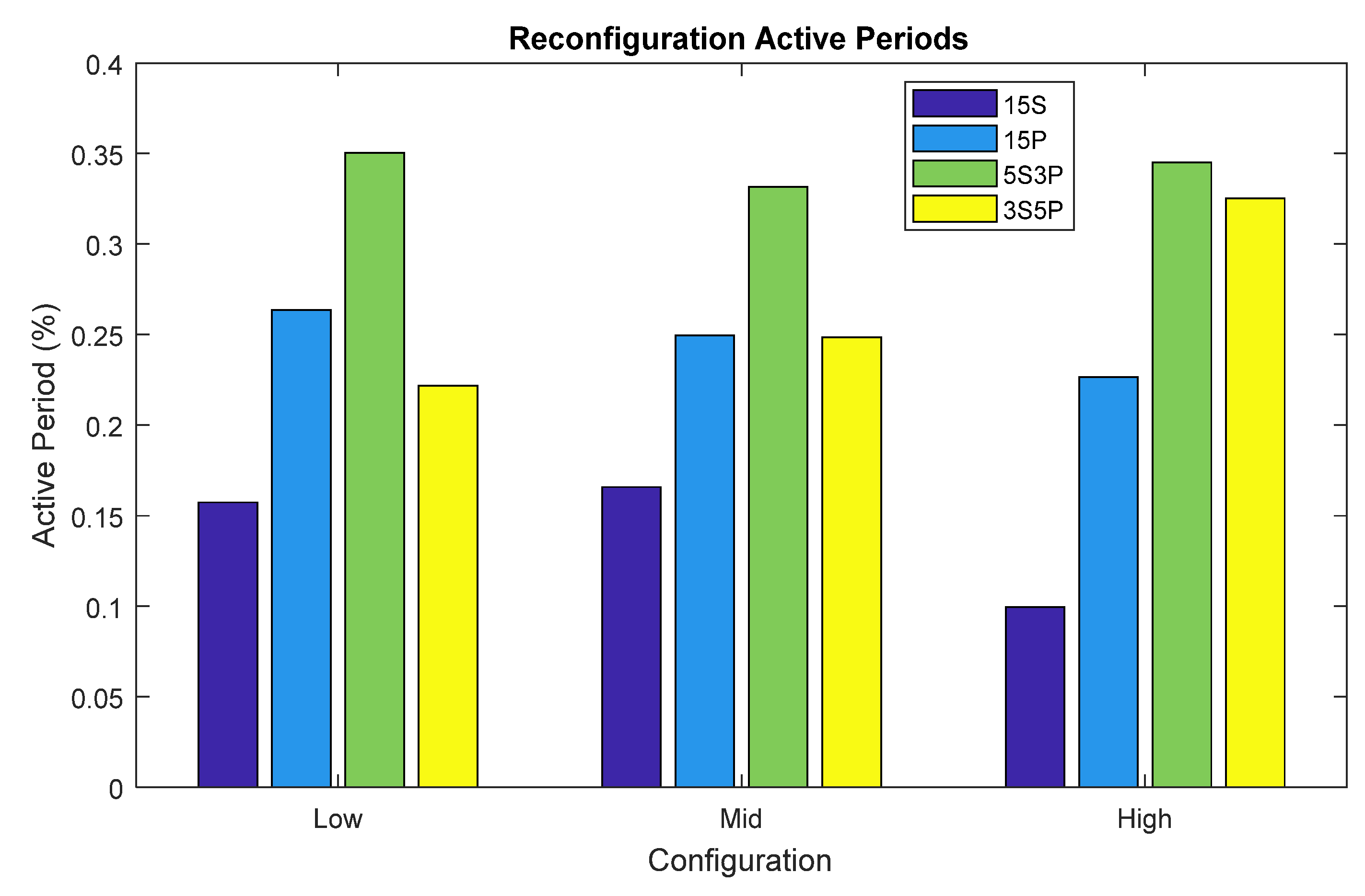
During normal operation, the ECS system was programmed to reconfigure every five minutes, with each cycle being subject to the availability of adequate energy. The control algorithm would adaptively reconfigure the MFCs based on the rate of change of power. Thus, as the rate of change of power increased, the topologies shifted towards a low Thévenin impedance and vice versa [28]. Analysing 200 days of data, a median power generation of 16.21 ± 0.77 mW was maintained with the configurations of series, parallel, 3P5S, and 5P3S at a daily active percentage of 0.17, 0.25, 0.33 and 0.25%, respectively (Figure 8). During low-power-output periods, a mean power level of 29.75 ± 0.35 mW was maintained at a daily activity percentage vector of (0.16, 0.26, 0.35, 0.22)%; likewise, at high power output, a mean power level of 34.77 ± 0.77 mW was maintained at a daily activity percentage vector of (0.1, 0.23, 0.35, 0.32)%. Based on Thévenin resistances of series and parallel networks of MFCs, for a given low impedance load, as the Thévenin resistance increases in a series network, unless the matched load decreases, the MFCs will be under stress to deliver equivalent power. The results corroborate this model, whereby the series topology indicates higher loading in comparison to the parallel one. As power increases, the time spent on parallel and series topologies is less. More time is spent on mid topologies, which enable a balance of loading. It was observed that the system selected the configuration 3S5P. Topologically, this configuration provided an apt balance between parallel and series configurations during peak power-harvesting periods. When power was lowest, the system maintained itself by choosing parallel configurations, which prevented suboptimal performance (also known as ‘weakening’), which can result in weaker cells reversing their polarity, so any form of a series topology is harmful. These are findings that can nicely feed into novel AI strategies in further optimising MFC systems, and this will form part of our future work.
Performing as a digital data generator, the overall activity of the MFC-powered bio-digital interface was digitally represented. All critical parameters (including, but not limited to, MFC voltages, power, current, system states, temperature) for monitoring the system were transmitted from the ECS to a remote server, where users can monitor and interact with the system.

3.3. Bio-Digital Interface

A bio-digital interface where users can virtually interact with live microbes in the real MFC system was developed, as shown in Figure 9. Visitors would remotely access a full-screen website, which presents an abstract world of animated microbes (‘mobes’) moving, feeding and colonising in response to the data streaming from the MFC array installed in the laboratory. Viewers can interactively engage with the mobes simulations and see real-time data, which provides the ability to understand the microbial behaviour affected by the interactions. Technical information about the live system is also available for viewing. A live video feed from the lab, which captures the real-time action of the MFC system that is generating the data informing the animations, is also accessible.
The animated work considers the conceptual commonalities between data and microbes, including the different types of power they each harness (for example, MFCs generate electrical power; data are a power behind many critical decisions), and the social preconceptions which surround both data and microbes (for example: abundance, necessity, cleanliness). The algorithm used as a basis for the behaviours of the mobes in this work was from [29]. A bacterial foraging optimisation algorithm (BFOA) with social communication is used as a framework for the animated microbes by providing each mobe with a set of rules that generate a random walk within a two-dimensional area. The BFOA is ‘seeded’ with parameters, such as the number of microbial communities, the population of each and a fitness value. The close-to-real-time fluctuating data from the MFCs then directly affects the mobility of each mobe (direction, speed, step distance) and their attraction or repulsion to the matrix or food. The form of each mobe is designed as a minimal scalable vector graphic (SVG) with flexible anchor points which animate a Bézier curve. As the anchor points change in response to data, the mobes appear to flap and rotate. The animated world which emerges shows the fluctuating nature of the MFC outputs and is an artwork which raises questions about how we translate microbial data as a visual microbial system. It aims to be an experience to convey life, rather than a typical data visualisation, using data as an art material [30] to ‘power’ the animation.
This participatory technology–art experience is currently available on the website (https://mobes.alice-interface.eu, accessed on 12 December 2021) and is based on the first bio-digital interface powered by MFCs. Providing an interesting and stimulating space for thorough creative encounters with microbes, it generates innovative learning opportunities and striking artistic experiences. This was also exhibited at the Digital Design Weekend (24–26 September 2021, V&A Museum, London, UK) and received a great deal of public interest (Figure 10).

4. Conclusions

The first human–microbial interactive bio-digital interface powered by MFCs was developed and continuously operated over a one-year period. The system operated as a self-sustainable digital data generator, which produced an average power of 28.36 ± 5.5 mW (9.45 W/m3). This level of power was sufficient to power data logging and data transmission, LEDs, system sensing and system control through adaptive dynamic cell reconfiguration. The dynamic reconfiguration allowed better maintenance of the microbial communities inside the MFCs, which resulted in establishing steady states and a consistent performance.
In addition to these technical achievements, the bio-digital interface as a site for digital art is presently scheduled for online public exhibitions. Enabling the visualisation of the otherwise invisible actions of microbes, the data art is expected to inspire users and the general public, thus helping them to understand how a complex biotechnology can be beneficial for society in the long term.

Author Contributions

Conceptualization, R.A., R.H., J.F., I.A.I. and J.G.; methodology, A.M., S.W. and J.Y.; software, A.M. and S.W.; formal analysis, A.M. and J.Y.; investigation, A.M. and J.Y.; writing—original draft preparation, A.M. and J.Y.; writing—review and editing, R.A., J.F. and I.A.I.; visualization, A.M., J.F. and J.Y.; funding acquisition, R.A., R.H., J.F., I.A.I. and J.G. All authors have read and agreed to the published version of the manuscript.

Funding

This project has been funded by the European Union’s Horizon 2020 Innovation Action Programme, grant no. 851246. IAI is a Bill & Melinda Gates Foundation grantee, grant no. INV-006499.

Institutional Review Board Statement

Not applicable.

Conflicts of Interest

The authors declare no conflict of interest.

References

  1. Potter, M.C. Electrical effects accompanying the decomposition of organic compounds. Proc. R. Soc. B Biol. Sci. 1911, 84, 260–276. [Google Scholar] [CrossRef]
  2. You, J.; Greenman, J.; Ieropoulos, I.A. Microbial fuel cells in the house: A study on real household wastewater samples for treatment and power. Sustain. Energy Technol. Assess. 2021, 48, 101618. [Google Scholar] [CrossRef]
  3. Khandaker, S.; Das, S.; Hossain, M.T.; Islam, A.; Miah, M.R.; Awual, M.R. Sustainable approach for wastewater treatment using microbial fuel cells and green energy generation—A comprehensive review. J. Mol. Liq. 2021, 344, 117795. [Google Scholar] [CrossRef]
  4. Munoz-Cupa, C.; Hu, Y.; Xu, C.; Bassi, A. An overview of microbial fuel cell usage in wastewater treatment, resource recovery and energy production. Sci. Total Environ. 2021, 754, 142429. [Google Scholar] [CrossRef]
  5. Walter, X.A.; Merino-Jiménez, I.; Greenman, J.; Ieropoulos, I. PEE POWER® urinal II—Urinal scale-up with microbial fuel cell scale-down for improved lighting. J. Power Sources 2018, 392, 150–158. [Google Scholar] [CrossRef]
  6. Ieropoulos, I.A.; Stinchcombe, A.; Gajda, I.; Forbes, S.; Merino-Jimenez, I.; Pasternak, G.; Sanchez-Herranz, D.; Greenman, J. Pee power urinal—Microbial fuel cell technology field trials in the context of sanitation. Environ. Sci. Water Res. Technol. 2016, 2, 336–343. [Google Scholar] [CrossRef] [Green Version]
  7. You, J.; Staddon, C.; Cook, A.; Walker, J.; Boulton, J.; Powell, W.; Ieropoulos, I. Multidimensional Benefits of Improved Sanitation: Evaluating ‘PEE POWER®’ in Kisoro, Uganda. Int. J. Environ. Res. Public Health 2020, 17, 2175. [Google Scholar] [CrossRef] [PubMed] [Green Version]
  8. Bixio, D.; Thoeye, C.; De Koning, J.; Joksimovic, D.; Savic, D.; Wintgens, T.; Melin, T. Wastewater reuse in Europe. Desalination 2006, 187, 89–101. [Google Scholar] [CrossRef]
  9. Lee, H.; Tan, T.P. Singapore’s experience with reclaimed water: NEWater. Int. J. Water Resour. Dev. 2016, 32, 611–621. [Google Scholar] [CrossRef]
  10. ALICE Consortium ALICE Interface—Active Living Infrastructure: Controlled Environment. Available online: https://alice-interface.eu/ (accessed on 16 September 2020).
  11. LIAR Consortium Living Architecture—Transform Our Habitats from Inert Spaces into Programmable Sites. Available online: https://livingarchitecture-h2020.eu/ (accessed on 10 September 2019).
  12. Gajda, I.; You, J.; Santoro, C.; Greenman, J.; Ieropoulos, I.A. A new method for urine electrofiltration and long term power enhancement using surface modified anodes with activated carbon in ceramic microbial fuel cells. Electrochim. Acta 2020, 353, 136388. [Google Scholar] [CrossRef]
  13. Walter, X.A.; Greenman, J.; Ieropoulos, I.A. Microbial fuel cells directly powering a microcomputer. J. Power Sources 2020, 446, 227328. [Google Scholar] [CrossRef] [PubMed]
  14. You, J.; Wallis, L.; Radisavljevic, N.; Pasternak, G.; Sglavo, V.M.; Hanczyc, M.M.; Greenman, J.; Ieropoulos, I. A Comprehensive Study of Custom-Made Ceramic Separators for Microbial Fuel Cells: Towards “Living” Bricks. Energies 2019, 12, 4071. [Google Scholar] [CrossRef] [Green Version]
  15. Brooks, T.; Keevil, C.W. A simple artificial urine for the growth of urinary pathogens. Lett. Appl. Microbiol. 1997, 24, 203–206. [Google Scholar] [CrossRef] [PubMed]
  16. Melhuish, C.; Ieropoulos, I.; Greenman, J.; Horsfield, I. Energetically autonomous robots: Food for thought. Auton. Robots 2006, 21, 187–198. [Google Scholar] [CrossRef]
  17. Ieropoulos, I.; Greenman, J.; Melhuish, C.; Horsfield, I. EcoBot-III: A robot with guts. In Proceedings of the Alife XII Conference, Odense, Denmark, 19–23 August 2010; pp. 733–740. [Google Scholar]
  18. You, J.; Greenman, J.; Ieropoulos, I. Novel analytical microbial fuel cell design for rapid in situ optimisation of dilution rate and substrate supply rate, by flow, volume control and anode placement. Energies 2018, 11, 2377. [Google Scholar] [CrossRef] [Green Version]
  19. Jadhav, G.S.; Ghangrekar, M.M. Performance of microbial fuel cell subjected to variation in pH, temperature, external load and substrate concentration. Bioresour. Technol. 2009, 100, 717–723. [Google Scholar] [CrossRef]
  20. Corbella, C.; Puigagut, J. Improving domestic wastewater treatment efficiency with constructed wetland microbial fuel cells: Influence of anode material and external resistance. Sci. Total Environ. 2018, 631–632, 1406–1414. [Google Scholar] [CrossRef]
  21. Grondin, F.; Perrier, M.; Tartakovsky, B. Microbial fuel cell operation with intermittent connection of the electrical load. J. Power Sources 2012, 208, 18–23. [Google Scholar] [CrossRef]
  22. Walter, X.A.; Greenman, J.; Ieropoulos, I.A. Intermittent load implementation in microbial fuel cells improves power performance. Bioresour. Technol. 2014, 172, 365–372. [Google Scholar] [CrossRef] [Green Version]
  23. An, J.; Li, N.; Wan, L.; Zhou, L.; Du, Q.; Li, T.; Wang, X. Electric field induced salt precipitation into activated carbon air-cathode causes power decay in microbial fuel cells. Water Res. 2017, 123, 369–377. [Google Scholar] [CrossRef]
  24. Al Lawati, M.J.; Jafary, T.; Baawain, M.S.; Al-Mamun, A. A mini review on biofouling on air cathode of single chamber microbial fuel cell; prevention and mitigation strategies. Biocatal. Agric. Biotechnol. 2019, 22, 101370. [Google Scholar] [CrossRef]
  25. Faíña, A.; Nejatimoharrami, F.; Stoy, K.; Theodosiou, P.; Taylor, B.; Ieropoulos, I. EvoBot: An Open-Source, Modular Liquid Handling Robot for Nurturing Microbial Fuel Cells; MIT Press: Cambridge, MA, USA, 2016. [Google Scholar]
  26. Papaharalabos, G.; Greenman, J.; Stinchcombe, A.; Horsfield, I.; Melhuish, C.; Ieropoulos, I. Dynamic electrical reconfiguration for improved capacitor charging in microbial fuel cell stacks. J. Power Sources 2014, 272, 34–38. [Google Scholar] [CrossRef]
  27. Papaharalabos, G.; Stinchcombe, A.; Horsfield, I.; Melhuish, C.; Greenman, J.; Ieropoulos, I. Autonomous energy harvesting and prevention of cell reversal in MFC stacks. J. Electrochem. Soc. 2017, 164, H3047–H3051. [Google Scholar] [CrossRef] [Green Version]
  28. Jaeger, R.C.; Blalock, T.N. Microelectronic Circuit Design; McGraw-Hill: New York, NY, USA, 1997; ISBN 0070324824. [Google Scholar]
  29. Brabazon, A.; O’Neill, M.; McGarraghy, S. Chapter 11. Bacterial Foraging Algorithms. In Natural Computing Algorithms; Springer: Berlin/Heidelberg, Germany, 2015; pp. 187–199. ISBN 978-3-662-43630-1. [Google Scholar]
  30. Freeman, J.; Wiggins, G.; Starks, G.; Sandler, M. A concise taxonomy for describing data as an art material. Leonardo 2018, 51, 75–79. [Google Scholar] [CrossRef] [Green Version]
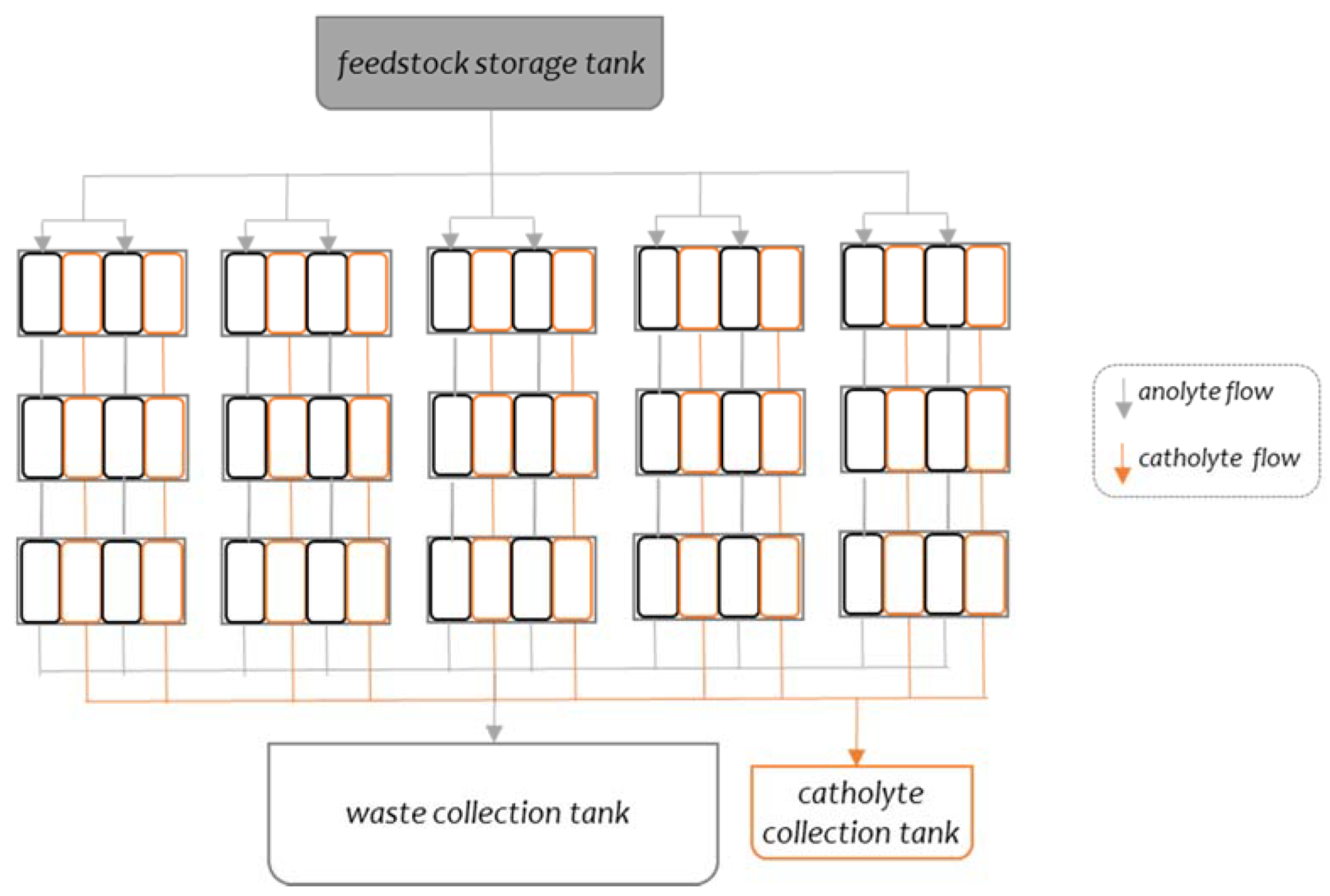
Figure 1. Flow diagram of the system. The black- and orange-coloured squares represent the anode and cathode chambers, respectively.
Sustainability 14 01735 g001
Figure 2. System high level functional block diagram.
Sustainability 14 01735 g002
Figure 3. Cell reconfiguration module design.
Sustainability 14 01735 g003
Figure 4. Responsive feedback loop between MFC microbial metabolism and planned interactive user experience.
Sustainability 14 01735 g004
Figure 5. Polarisation and power curves of 15 individual matured MFCs measured on day 20. Each data point represents the average value of all MFCs (n = 15).
Sustainability 14 01735 g005
Figure 6. Harvester performance: mean instantaneous power variation, mean instantaneous voltage variation and actuations per day.
Sustainability 14 01735 g006
Figure 7. The MFC system in action, with the LED lights (located in upper left corner) switched on.
Sustainability 14 01735 g007
Figure 8. Configuration percentages for low-, mid- and high-power levels.
Sustainability 14 01735 g008
Figure 9. Exemplar interactive elements of the mobes user interaction interface (a) and exemplar user data visualisation application animating mobes (b). Images produced by Translating Nature.
Sustainability 14 01735 g009
Figure 10. Bio-digital interface technology-art experience at the V&A Museum as part of the Digital Design Weekend, London Design Festival, 2021.
Sustainability 14 01735 g010
Publisher’s Note: MDPI stays neutral with regard to jurisdictional claims in published maps and institutional affiliations.