Article

Carbon Fibers Waste Recovery via Pyro-Gasification: Semi-Industrial Pilot Plant Testing and LCA

1
Department of Industrial Chemistry “Toso Montanari”, University of Bologna, Viale Risorgimento 4, 40136 Bologna, Italy
2
Interdepartmental Centre of Industrial Research “Renewable Sources, Environment, Sea and Energy”, University of Bologna, Via Dario Campana 71, 47922 Rimini, Italy
3
CURTI S.p.A., Divisione Energia, Via Emilia Ponente 750, 48014 Castel Bolognese, Italy
4
Interdepartmental Centre of Industrial Research “Mechanics and Advanced Materials”, University of Bologna, Viale Risorgimento 2, 40136 Bologna, Italy
*
Authors to whom correspondence should be addressed.
Sustainability 2022, 14(7), 3744; https://doi.org/10.3390/su14073744
Submission received: 8 February 2022 / Revised: 15 March 2022 / Accepted: 18 March 2022 / Published: 22 March 2022
(This article belongs to the Special Issue Advanced Waste Technologies for Sustainable Materials and Products)

Abstract

:
Carbon-fiber-reinforced polymers (CFRPs) are increasingly used in a variety of applications demanding a unique combination of mechanical properties and lightweight characteristics such as automotive and aerospace, wind turbines, and sport and leisure equipment. This growing use, however, has not yet been accompanied by the setting of an adequate recycling industry, with landfilling still being the main management route for related waste and end-of-life products. Considering the fossil-based nature of carbon fibers, the development of recovery and recycling technologies is hence prioritized to address the environmental sustainability challenges in a bid to approach mitigating the climate emergency and achieving circularity in materials’ life cycles. To this aim, we scaled up and tested a novel semi-industrial pilot plant to pyrolysis and subsequent oxidation of uncured prepreg offcuts and cured waste of CFRPs manufacturing. The environmental performance of the process proposed has been evaluated by means of a life cycle assessment to estimate the associated carbon footprint and cumulative energy demand according to three scenarios. The scale-up of the process has been performed by investigating the influence of the main parameters to improve the quality of the recovered fibers and the setting of preferable operating conditions. The pyro-gasification process attested to a reduction of 40 kgCO2eq per kg of recycled CFs, compared to virgin CFs. If the pyro-gasification process was implemented in the current manufacturing of CFRPs, the estimated reduction of the carbon footprint, depending on the composite breakdown, would result in 12% and 15%. This reduction may theoretically increase up to 59–73% when cutting and trimming waste-optimized remanufacturing is combined with circular economy strategies based on the ideal recycling of CFRPs at end-of-life.

1. Introduction

The widespread adoption of carbon fibers (CFs) in a multitude of areas and emerging applications, including automotive, aerospace and defense, wind turbines, and sport and leisure equipment, is constantly increasing. Indeed, the demand for CFs reached 63,500 tonnes in 2016, approximately 77,000 tonnes in 2018, and it is forecasted to achieve 117,000 tonnes by 2022 [1,2]. Such growth is mainly due to the peculiar combination of extraordinary mechanical properties and lightweight, particularly when CFs are used as reinforcement in a polymer matrix to obtain carbon-fiber-reinforced polymers (CFRPs).
The global market size of CFs and CF composites is projected to grow from USD 17.5 billion in 2020 to USD 31.5 billion by 2025, at a CAGR of 12.4% during the forecast period, with wind energy and aerospace being expected to drive the demand most significantly. Before the COVID-19 pandemic, Europe accounted for more than 50% of commercial aircraft production worldwide, and the European region led in offshore wind energy installations in 2019. The world market for CF in the automotive industry was estimated at 7000 tonnes/year with a projection to grow to 11,000 tonnes by 2025. Overall, the estimated global demand averages 65,000–85,000 tonnes/year [2].
The proliferation of the use of CFRPs, on the other hand, will result in an increase in waste streams arising from manufacturing processes (e.g., prepregs, cured composites offcuts, and similar “new scrap”) and post-consumer goods or “old scrap”. Currently, around 30% of produced CFs end up in landfills, and with new regulations, some 80,000 tonnes/year of CFRPs should undergo recycling in Europe. Consequently, the research and development of recycling technologies for CFRPs is growing, aiming at pursuing environmentally and economically sustainable strategies for the reduction of material losses and waste disposal [3,4,5,6,7,8].
Further momentum toward high-performance composite recycling may also derive from policy drivers and legislation. For instance, the 2000/53/EC Directive on end-of-life vehicles (ELVs) calls for the achievement of specific recovery and recycling targets by car weight, requiring that the materials used in vehicle manufacturing could be easily retrieved [9]. As of today, most materials currently recovered during ELV shredding operations mainly include iron/steels and non-ferrous metals such as aluminum and copper. However, the increasing use of composites in new car manufacturing for lightweight purposes, in contrast to the climate emergency [10,11,12,13], will make the adoption of circular business models and the improvement of recycling efficiency of CFRPs of primary importance. Notwithstanding this potential for recycling, the main limitation of composite recycling is the presence of thermosetting polymer matrices. This downside could be partially addressed by using a thermoplastic polymer matrix, which might allow for the reuse of the composites via reshaping. Nevertheless, the most widespread recycling methods for CFRPs could be subdivided into two categories: (a) Mechanical recycling and (b) fiber recovery through thermal or chemical processing [14,15]. The former category is based on the recovery of the composite via mechanical processes such as shredding, crushing, or milling, without any further separation of material components. Composites are, thus, reduced in a powder that can be used in low-value applications, primarily as fillers or particle reinforcements [16,17]. Despite being an actual method to reclaim composite wastes, it is worth noting that, in this way, the high production cost, in economic and environmental terms, and added value of the CFs would be basically lost.
For these reasons, the appeal of recycling processes that could return CFs that can go back over the production paths, allowing the achievement of a cradle-to-cradle system and the closure of the material life cycle, is far superior. Both chemical and thermal recovery belonging to these processes could be considered better options for CFRPs recycling.
Chemical recycling methods for CFRPs, of which solvolysis is an example, take advantage of the application of solvents and reagents able to attack, decompose, or dissolve the polymer matrix. This approach, however, involves the use of solvents, chemicals, and catalysts, and long process times or strong process conditions such as, for instance, using supercritical and subcritical fluids [18,19]. Even though the recovered CFs seem to be generally undamaged during these chemical recycling processes, all the aforementioned factors result in low industrial scalability, due to the high environmental impacts and risks, as well as the high operating costs. As an alternative, thermal recycling processes decompose the polymer matrix by applying a moderately high temperature. Moreover, these processes are characterized by high energy consumption but, according to the estimates found in the literature, to a lesser extent compared to the previous ones [20].
However, thermal recycling allows the reclaim of CFs with good mechanical properties, and in various states depending on the atmosphere used in the reactor. For example, thermal processes operated in the complete absence of oxygen, as in pyrolysis, yield fibers covered by a thin layer of pyrolytic carbon [21,22], but the process also generates syngas, partially condensable as oil, which can be potentially used to meet the energy demand of the process itself [23,24]. On the contrary, the use of an oxidizing atmosphere leads to complete oxidation (i.e., burning) of the polymer matrix to valueless products [25], leaving fibers perfectly clean from any carbonaceous residue but with modified surface chemistry [26,27,28].
Under these premises, the study of a multi-stage process, comprising the first stage of pyrolysis of uncured prepregs and related cured composites (new) scrap followed by a controlled oxidation step to remove the carbonaceous residue deposited on the fibers, was previously proposed [29]. The authors proved that the above-mentioned approach allows for the recovery of chemical feedstocks or valuable fuels from the polymer matrix and simultaneous fiber separation and quantitative recovery. In particular, the first step was performed in a pyrolysis pilot plant [30] that has been previously used and was proven to be efficient in the potential recovery of other composite wastes such as glass-fiber-reinforced polymers (GFRPs) [31] or end-of-life tires [29]. The following oxidation step (gasification) was instead performed and optimized using a laboratory furnace on small batches (about 10–100 g) of pyrolyzed CFRPs.
The present work is intended to illustrate the further evolution of the multi-step process previously proposed, which has been scaled up to a novel semi-industrial experimental pilot plant [32] capable of performing, in the same reactor, both pyrolysis and the subsequent oxidation steps (from now on referred to as “pyro-gasification”). In this study, the plant has been tested with uncured prepreg offcuts and cured waste. The effects of the process on the recovered fibers were evaluated by SEM analysis. Moreover, the environmental performance of the novel process proposed is evaluated by applying the life cycle assessment (LCA) methodology, with the goal of determining the environmental benefits achievable from the recovery of materials and energy in comparison with the current production of finished CFRPs. In this view, the main outcomes of this research are expected to contribute to the development of the pyro-gasification recycling process to the full scale and to provide guidance to the achievement of material circularity and greenhouse gas (GHG) emissions reduction in the current life cycle of CFRPs.

2. Materials and Methods

2.1. Materials

The CFRPs samples used for the experimental tests and optimization of this new pilot plant were provided confidentially by an automotive company and one of its main suppliers. These waste materials include (see also Table 1):
(i)
Scrap of long-fibers fabric containing 62% w/w of Toray T700-6K CFs impregnated with epoxy resin (38% w/w);
(ii)
Scrap of cured CFRP based on a vinyl-ester resin (57% w/w) and 43% w/w of chopped short-fibers of 5 cm based on the same Toray T700-6K CFs;
(iii)
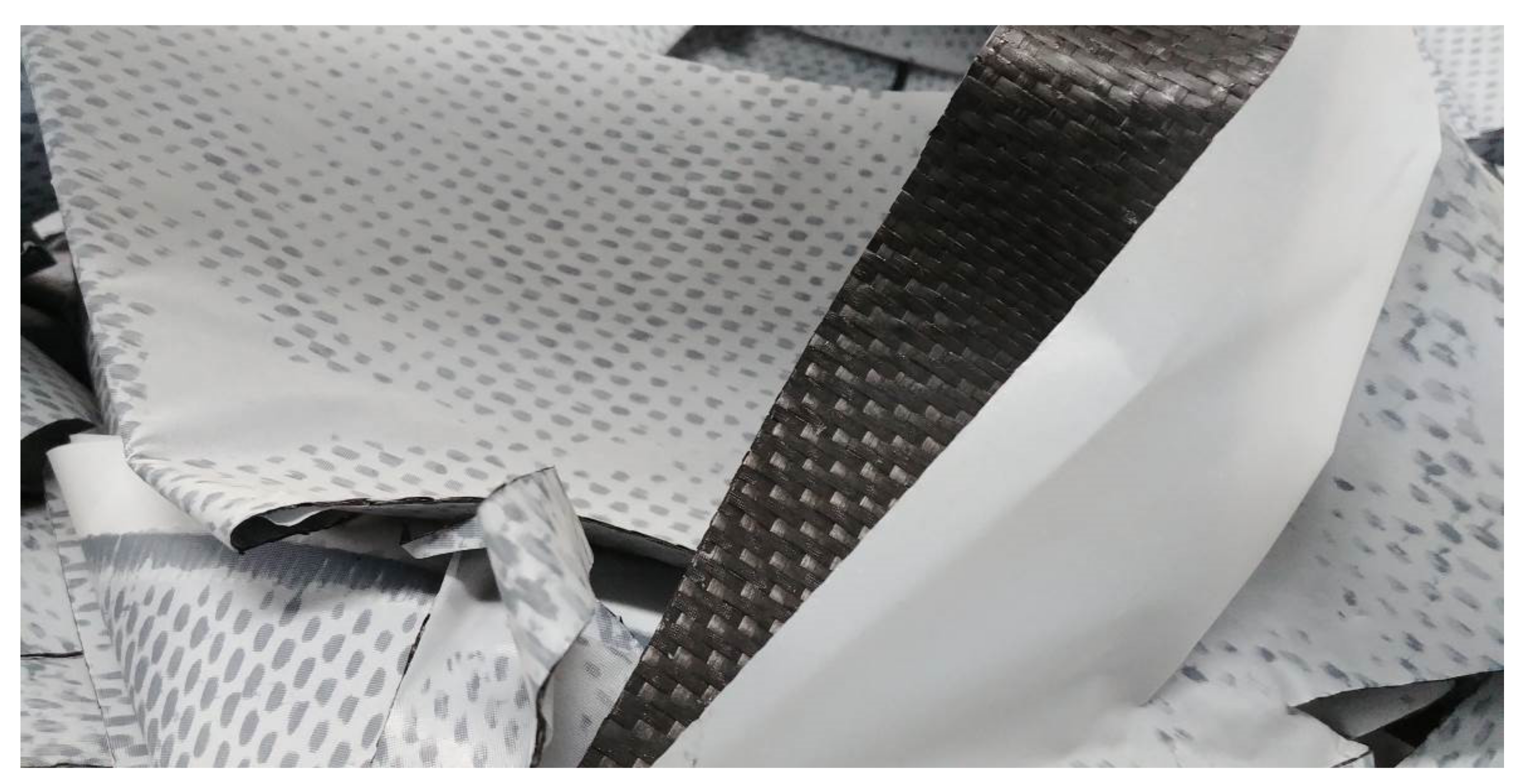
Offcuts of woven long-fibers fabric containing 52% w/w of Toray T700-6K CFs impregnated with an uncured epoxy resin (33% w/w) and having polyethylene (PE) protective sheets (15% w/w) on both sides (from now on referred to as “prepreg”, see Figure 1).
Cured A and cured B were assumed to be manufactured via a sheet molding compound. All samples (about 10 kg/batch) were loaded into the reactor without any pre-treatment (i.e., no cutting, shredding, or other size-reducing operations). The PE protective sheets were not removed because they are completely converted in the pyrolysis step to syngas and pyrolysis oil, as previously reported [33], and do not interfere with the CF recovery.

2.2. Pyro-Gasification Experiments in the Batch Pilot Plant
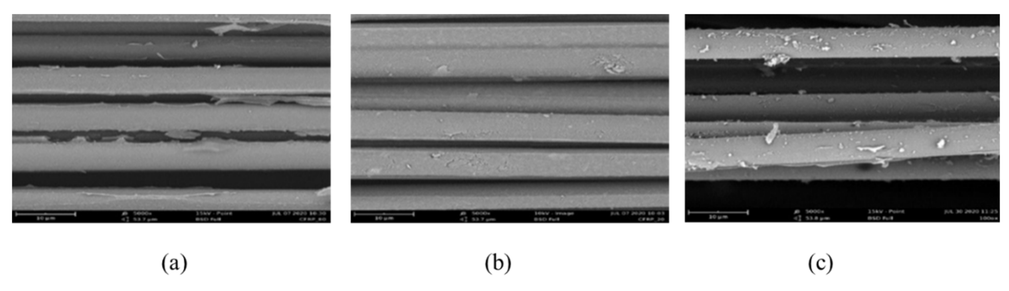
The CFRPs pyro-gasification experiments were carried out in a batch semi-industrial pilot plant owned by Curti S.p.A. at their site, which is able to treat up to 10 kg of CFRPs materials per cycle. Each batch was run by setting the process parameters to optimize the recycled carbon fibers (rCFs) output. Different temperatures for pyrolysis and oxidation stages, namely 500, 510, and 520 °C, as well as different oxidation times (50 to 150 min) were tested. Moreover, the influence of the volumetric flow rate of air, the turbulence in the reactor ensured by an inverter-driven controlled fan, and the bulk density of the prepregs were modelled as process parameters. A summary of the experimental conditions tested is reported in Table 2.
In a typical cycle, CFRPs scraps are placed into a sample holder cage and the cage is loaded into the reactor chamber. After closing the reactor hatch, the chamber is flushed with nitrogen to remove air. Then, the system is heated with a heating rate of approximately 8 °C/min up to the set point, and after 20 min in the pyrolysis condition at that temperature, air is injected in the reactor chamber until the end of the oxidation step of amorphous char deposited on the rCFs during the pyrolysis step. After that, the heating is interrupted, and nitrogen is fluxed again in the chamber to stop oxidation reactions and favor faster cooling of the system. All the gases generated in the process are conveyed outside the reactor to a burner kept above 750 °C and could be used to generate electric energy.

2.3. TGA and SEM

Thermogravimetric (TGA) analysis was carried out using a TA Instruments SDT-Q600 instrument. Preliminary pyrolysis experiments were carried out on approximately 10 mg of material in a nitrogen atmosphere from RT to 700 °C at a 10 °C/min heating rate. The analysis for the oxidizing step simulation was performed under an airflow of 20 mL/min heating at a rate of 25 °C/min from RT to 500 and 600 °C and then kept in isotherm. These analyses also confirmed the CFs content in the composites investigated.
To investigate the morphological aspect of the fibers after pyro-gasification treatments, micrographs were taken with a Scanning Electron Microscope (SEM) ZEISS EVO 50 EP in Environmental mode with ≈100 Pa pressure in the chamber. The distribution of fiber diameters was determined by means of image analysis software, measuring about 50 fibers in two different images (25 fibers per image) per fiber type.

2.4. Life Cycle Assessment

LCA is the preferred technique for quantitative estimation of environmental impacts associated with a product system, service, or waste. The ISO standards 14040–14044 series frame LCA on four conceptual phases, namely (i) goal and scope definition, (ii) life cycle inventory (LCI), (iii) life cycle impact assessment (LCIA), and (iv) interpretation. While the former three phases are consequential, interpretation is transversal to all to ensure consistency between the aims of the study, methodological assumptions, and result computation.
LCA has been previously applied to explore the environmental consequences of virgin CFs (vCFs), recycled CFs (rCFs), as well as CFRPs production, recovery, and disposal [4,5,11,34,35,36,37,38,39,40]. Here, we used LCA to assess the environmental benefits achievable by implementation of our pyro-gasification process in the current manufacturing procedure of CFRPs and the related scenario for waste disposal, ultimately to provide guidance for the development of a circular production model for CFRPs.

2.4.1. Goal and Scope Definition

This phase includes the definition of spatial and temporal boundaries as well as the setting of the functional unit (FU). The production of finished CFRPs was set as FU, and 1 kg of finished CFRP (kgfinished CFRP) was the reference flow for quantitative analysis, with material and energy inflows and outflows and the related environmental impacts being normalized to this amount.
Three scenarios were modelled and compared to address the main goal of this study, namely:
Scenario 1—vCFs (current mfg): This scenario describes the current manufacturing process of molding and cutting CFRPs to finished products. Process efficiency rates (measured as the percent ratio of the amount of useful outflow over the amount of inflow) are assumed to be 100% for molding and 80% for cutting. The loss flow from cutting (i.e., 20% of the inflow) is disposed to landfill, with this being the current treatment option for CFRPs trimming waste.
Scenario 2—rCFs (new scrap): This scenario builds upon Scenario 1 and describes the implementation of the pyro-gasification process, presented and tested in this work, in the current management of the loss flow from cutting. CFs contained in this flow are assumed to be recovered with an ideal efficiency of 100% and re-entered into manufacturing as new scrap. Consequently, the inflow of vCFs is reduced by the same amount of rCFs inflow. Matrix resins of all offcuts and PE sheets of prepreg are only converted into pyrolysis gas and oil and burned before its release into the atmosphere.
Scenario 3—rCFs (new + old scrap): This scenario builds upon Scenario 2 and models the pyro-gasification of CFRPs at their end-of-life (i.e., old scrap) as the main source of CFs to manufacture. More specifically, in this scenario, only rCFs (new scrap and old scrap) are used to produce finished CFRPs. As for Scenarios 1 and 2, efficiency rates of the cutting process are assumed to remain constant as well as the post-combustion of pyrolysis gas and oil.
Figure 2 provides essential visualization of system boundaries, processes, and the main material and energy flow included in LCA modelling. More specifically, the flowsheet (a) describes the current manufacturing system that has been used to create Scenario 1—vCFs (current mfg), while the flowsheet (b) depicts the same system after the implementation of the pyro-gasification process and constitutes the basis for LCA modelling of Scenario 2—rCFs (new scrap) and Scenario 3—rCFs (new + old scrap).

2.4.2. Life Cycle Inventory

LCI unit processes for modelling the production of vCFs from polyacrylonitrile (PAN) synthesis via acrylonitrile (AN) were based on the inventory provided in [36] and further linked to the Ecoinvent database [41]: The average global markets for material and energy supply were considered. Energy consumption for cutting semi-finished CFRPs has been neglected, assumed to be comparable, while all scenarios include the environmental impacts associated with the compression molding of CFRPs, for which the Eco Impact Calculator [42] was used in the model.
LCI unit process for pyro-gasification is instead based on primary data measured at the plant, operating in batch with a supply capacity of 10 kg/cycle of input waste, and complemented with literature information [43,44].
To be conservative, the less-favorable configuration that assumes a complete transformation of the carbon contained in the epoxy resin, the vinyl ester resin, and PE sheets to CO2 has been considered. In reality, the composition of gas outflows depends on the breakdown of the waste inflow and operating conditions, which ultimately determine the species and relative quantities of greenhouse gas released. However, upon limiting the list of GHG species that can be potentially generated by the post-combustion process to CO and CO2, only the latter gas has a characterization factor formally standardized by the IPCC and incorporated into common LCA methods. Indeed, although CO is deemed to have an indirect effect on global warming, it is not attributed as a characterization factor (yet), so any combination of CO and CO2 in the system’s emission would result in a lower potential contribution to the climate emergency than our estimate.
Electrical energy has been modelled according to the Italian electricity mix for geographical correlation with the location of the pyro-gasification process investigated.
Material recycling of new scrap and old scrap is modelled according to the recycled content approach. This approach considers the fraction of secondary (i.e., recycled) material in the manufacturing of a product system. The environmental impacts related to resources extraction and their further processing are attributed to the first use of those resources in the product. The recycled material does not embody any environmental burden associated with the first use. In our case, the environmental impact of finished CFRPs is hence computed as the sum of the product of characterization factors of primary and secondary (i.e., recycled) materials multiplied by the respective amounts contained in finished CFRPs.
Specifically, the final structure of rCFs under the analyzed process is clearly dependent on the form loaded in the reactor. In the applied pyrolytic conditions, without prior milling, the obtained rCFs maintain the same arrangement they had in the original waste input [15]. On this basis, the hypothetical remanufacturing of the cured products and the prepreg was modelled under a closed-loop recycling perspective, i.e., rCFs are recycled into the same type of product.
We are aware that, although the recovered long fibers from Cured A can be theoretically reused as they are, in some cases, they may undergo a grinding process and be reused as short fibers. However, it is worth noting that the reuse of recovered fibers is entirely dependent on the final application and market dynamics for composites. In this view, any further processing (e.g., grinding, possible reinforcement with minimal addition of virgin fibers to compensate for strength loss) is product-specific [17], an exhaustive assessment of which is beyond the goal of this work.
In any case, from a mere mass balance perspective, the recycled amount of recovered fibers will substitute an equivalent amount of virgin fibers, independently from the fibers’ format. The difference between the carbon footprint of virgin fibers and that of recycled fibers should be intended here as a “carbon budget”. Part of this budget will be eroded by further refinement of the recovered fibers, if any, depending on the final product or application. In this view, our values are preliminary estimates rather than ultimate results. Despite the fact this assumption may lead to a partial, but not simplistic, view of the environmental benefits, it is consistent with most of the recycling-based literature [36,45] and provides a minimum carbon footprint estimation for the process investigated, which is, ultimately, informative in closing the life cycle of composites through re-manufacturing composite waste.

2.4.3. Life Cycle Impact Assessment

The life cycle impact assessment (LCIA) phase relates LCI to selected categories of environmental impacts and, eventually, damages. To this aim, environmental mechanisms and universally accepted models are applied. Here, we have selected the IPCC GWP 100a and Cumulative Energy Demand (CED) methods to compute the potential contribution to climate change and the gross energy requirements, respectively.

3. Results

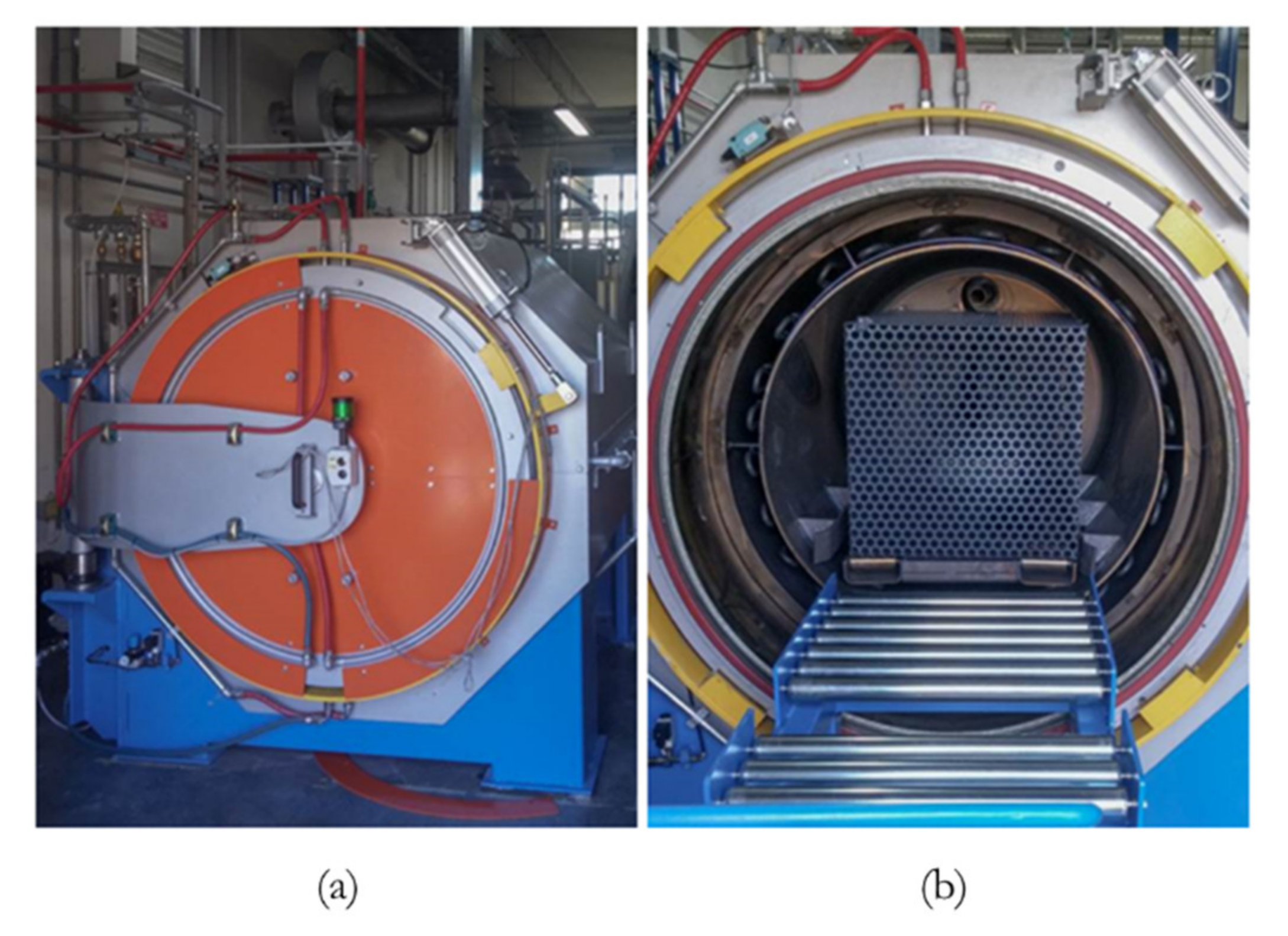
3.1. Description of the Pilot Plant

The core of this newly conceived pilot plant (Figure 3) is the semi-industrial scale reactor, designed to treat up to 15 kg of prepregs offcuts, while the maximum load of cured scraps greatly depends on their geometries and volumes. Theoretically, the reactor could accommodate a larger amount of material, but doing so would produce greater quantities of syngas and vapors that would make it necessary to adopt a bigger burner to manage the higher energy output generated by their combustion, as well as the false air needed to cool the exhaust gases prior to releasing them into the atmosphere. Additionally, a greater amount of material would result in a higher bulk density, which would lead to an inhomogeneous treatment.
The syngas and vapors produced during the pyrolysis step are extracted from the back side of the reactor and conveyed through short piping to the combustion chamber. The chamber is kept above a temperature of 750 °C thanks to the burning of syngas and vapors and is helped by a liquid propane gas-fueled gas-burner during the other stages of the cycle. This is necessary to ensure the complete destruction of any possible contaminant that could be released or dragged by the gases from the reactor. For safety reasons, the reactor operates in a slight overpressure granted by a regulation valve fixed at 25 millibar on the pipe connected to the combustion chamber. When the valve opens, the mixture of gases is discharged from the reactor, and, consequently, the pressure drops. The injection of the reaction gases (nitrogen and air) is carefully controlled thanks to mass flow meters, while the mixing of the atmosphere inside the reactor is obtained with a fan of variable speed. Different sensors are located along the whole pilot plant to monitor crucial parameters: Thermocouples, pressure sensors and switches, mass and volume flowmeters, and oxygen sensors. All the principal data (as shown for an experimental test at 510 °C in Figure 4) are continuously measured and stored by software that allows one to command all the operations from the control panel.

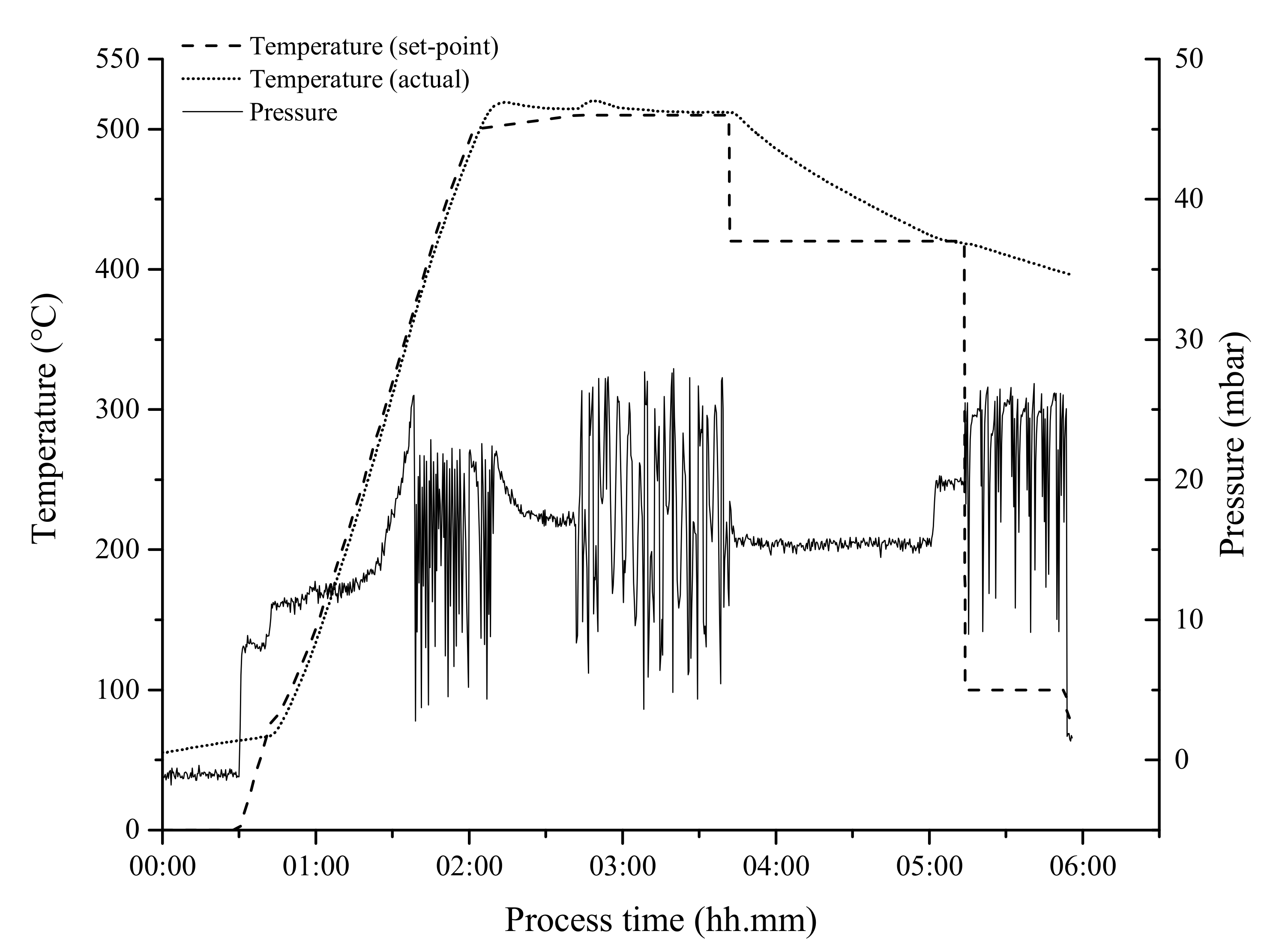
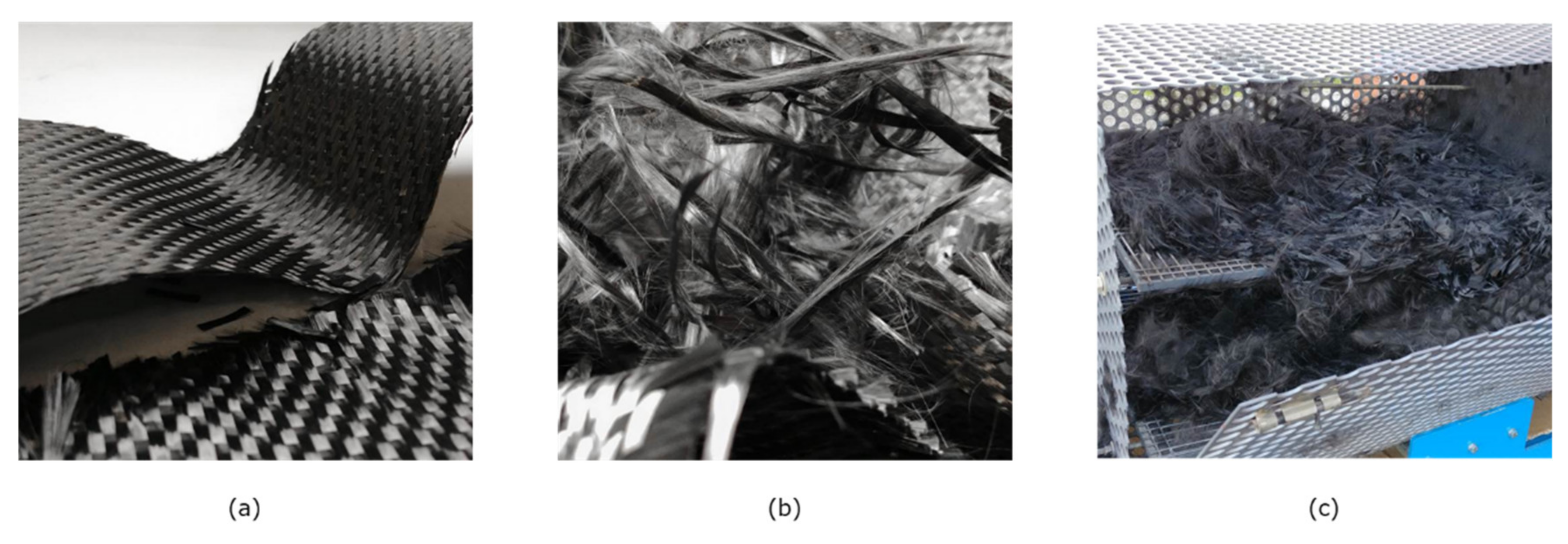
3.2. Optimization of the Pyro-Gasification Process

The scale-up of the process, in particular the gasification step that was previously performed at the laboratory scale, has been approached scientifically, evaluating the effect of one parameter at a time, starting from the definition of the correct amount of gasification air to perform the correct and quantitative oxidation of pyrolytic chair. The effect of temperature has been also investigated, even though extensive tests on the influence of temperature and the correlation with residence time were performed in previous work [45]. For this reason, only minor increases starting from the optimal temperature of 500 °C have been considered, finding 510 °C to be the best set-point temperature for the purposes of the research.
The next fundamental process parameter investigated was the duration of the gasification phase. The results obtained, starting from 50 min, which was the optimal time that emerged after the previous trial, were not satisfactory. In fact, the recovered fibers were still covered by carbonaceous residues and felt stiff to the touch (Figure 5). In these conditions, the obtained rCFs maintain the original arrangement they had in the waste input, as previously reported [15,45] and depicted in Figure 5.
To improve the quality of the recovered fibers, the gasification time was stepwise increased by 30 min to reach an excessive condition and narrow the field to rapidly find the optimal time. During this final tuning of the process, the first assessment of the success of each cycle was made by weighing the loaded sample and the recovered CFs, and therefore calculating the weight percentage loss. The theoretical value was determined considering a 60 to 65 wt% fiber content in the CFRPs and approximately 12 to 17 wt% of PE protective sheets in the prepregs scraps, as preliminarily determined by TGA measurements and previous pyrolysis tests at the lab scale. Thus, the resultant theoretical mass loss after pyro-gasification is between 50 and 52 wt%. The results obtained by mass loss calculations are reported in Table 2.
The weight losses measured and the relative diameter of rCFs follow a rather clear trend with the gasification time, which was easily foreseeable. We also observed a clear positive effect of increasing the reactor fan speed from 75 to 100% (cfr. Tests #1 and #2), as well as a slight effect of the doubling of the shelves used in the cage sample holder, resulting in a decrease in bulk density and, thus, better homogeneity of the gasification treatment. Based on this, it seems that test #3 should be inside the calculated optimal range. However, the fibers reclaimed from that test are still rather stiff to the touch, while the fiber from tests #4–6 are softer and fluffier (Figure 5). Even though it is not a measurable parameter, this is undoubtedly an index of the quality of the treatment and a definite aid in discerning undertreated from good/overtreated fibers.
The SEM investigation of tests #4, 6, and 7 shows clean rCFs with an optimal diameter of approximately 6.90 microns (Table 3 and Figure 6). Therefore, treatment at 510 °C with a 120 min gasification resident time is a suitable condition for removing pyrolytic carbon on the surface of reclaimed carbon fibers without degrading the single rCF.
Following the tuning of the process with prepregs offcuts as the feed material, the first trial with cured CFRPs scrap pieces was performed. The process parameters chosen for this test were those from test #4 (Table 3). Moreover, in this case, the firsts assessments of the success of the test are the aspect and touch of the recovered fibers, as well as the actual weight loss (57% w/w) compared to the theoretical one (test #7 in Table 3).
The recovered short CFs from cured SMC scraps appeared soft and free from carbonaceous residues (Figure 5). However, a small amount of fine powder, due to additives of the vinyl-ester resin, was found on the fibers by SEM investigation (Figure 6).

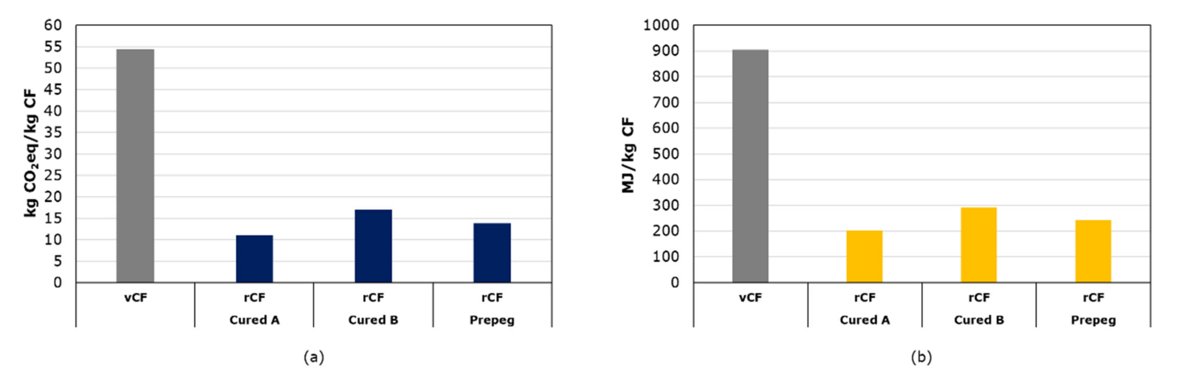
3.3. Life Cycle Assessment Results

In Figure 7, we compare the carbon footprint of 1 kg of vCFs and 1 kg of rCFs, with the latter distinguished among the three types of cuttings under investigation. The carbon differences between Cured A, Cured B, and Prepreg reflects the variations in their composition, such as the CFs content, type, and quantity of the resin, and these affect the results by indicating an order of (environmental) preference as follows: Cured A > Cured B > Prepreg.
Our results for rCFs align with literature results reported for a pyrolysis recycling process of CFRPs [44]. This correspondence with previous estimates also occurs in relative terms. In detail, a contribution analysis conducted on the three composite offcuts shows, in general, a homogeneous distribution among the composites in terms of the most impactful processes and materials. Specifically, the use of vCFs determines more than 78% of the total carbon footprint in the case of Cured B, which reaches up to 86% and 87% for Cured A and Prepreg, respectively. Epoxy resin (for Cured A and Prepreg) and vinyl ester resin (for Prepreg) contribute 6% and 11%. In the Prepreg, a further 5% is attributed to the PE sheets. A similar percentage characterizes the sheet molding process applied to the two cured composites. The rCFs from the pyro-gasification process contribute approximately 6% in all three CFRPs, underlying the sustainability of recycling processes with respect to the production of virgin fibers. On average, more than 80% of the recycling process’ impact is attributable to energy consumption, while the remaining fraction is a function of the (theoretical) CO2 emission exiting the post-combustion process, which, in turn, depends on the content of the matrix resin and the eventual content of PE sheets.
Despite these intrinsic variations, the reduction in the carbon footprint achievable by the pyro-gasification process is significant and can be estimated, on average, as about 40 kgCO2eq avoided per kg of rCF, approximately corresponding to −74% of the vCFs’ carbon footprint. Part of this carbon budget will be eroded by the collection, recovery, and separation processes, but the credit appears to be wide enough and particularly promising toward the process investigated.
In Figure 8, we compare the carbon footprint results for the three scenarios investigated in this study. In all panels, Scenario 1 shows the carbon footprint for a manufacturing process representative of the current state, with the amount of new scrap generated during the cutting phase being equivalent to 20% of the CFRP inflow. The possibility of recovering CFs through the pyro-gasification process (i.e., Scenario 2) has the dual advantage of reducing the consumption of natural resources and the impact associated with CO2 and energy needs. The estimated reduction for the carbon footprint is 6.7 kgCO2eq/kgfinished CFRP in the case of Cured A, 4.0 kgCO2eq/kgfinished CFRP for Cured B, and 5.3 kgCO2eq/kgfinished CFRP for Prepreg. In relative terms, the resulting percentage reduction corresponds to −14.5%, −11.7%, and −13.9%, respectively.
In Scenario 3, the simulation shows the impact that is likely to be associated with the implementation of circular economy strategies based on aggressive recycling of old scrap. In this case, replacing vCFs with an equivalent amount of rCFs from waste and EoL products would reduce the impact of Scenario 1 by 72.8% for Cured A, 58.9% for Cured B, and 69.6% for Prepreg. The related carbon footprint amounts to 12.5 kgCO2eq/kgfinished CFRP, 14.1 kgCO2eq/kgfinished CFRP, and 11.5 kgCO2eq/kgfinished CFRP. As an indicative estimate of the theoretical minimum value of the carbon footprint for which a virtuous circular system should aim, we consider the optimization of the manufacturing process in the absence of inefficiencies, i.e., with no cutting losses, and CFs supplied from old scrap only. According to this assumption, the estimated carbon footprint per kg of finished CFRP would result in 10.0 kgCO2eq for Cured A, 11.2 kgCO2eq for Cured B, and 9.2 kgCO2eq for Prepreg.
Similar considerations can be also extended to the CED results because of the correlation between GHG emissions and electricity inputs to the system. CED results are listed in Table 4.

4. Conclusions

In this study, we developed and tested a semi-industrial pilot plant for pyro-gasification of cured and uncured CFRPs offcuts and scrap. Continuous monitoring of the main parameters through in situ sensors enabled us to investigate the influence of process variables and the identification of the optimal operating conditions for achieving quality standards of the recovered CFs and quantitative oxidation of the pyrolytic char, which will be of great value in further improvements and scale-up of the process. Although the pilot plant has a maximum capacity of 15 kg, the test trial with different CFRPs offcuts and scrap demonstrated its flexibility and robustness to compositional variations, which is an essential characteristic for the full-scale development of recovery and recycling technologies.
These promising results are also supported by LCA outcomes, which estimated the significant potential for mitigating the release of greenhouse gas emissions from current CFRPs manufacturing operations as well as for reducing the reliance on fossil sources for CFs production. On average, compared to vCFs, the estimated reduction in the carbon footprint achievable by the pyro-gasification process amounted to about 40 kgCO2eq per kg rCF (or −74%). These LCA results should be considered as preliminary estimates rather than ultimate outcomes due to (i) inherent uncertainty related to modelling a pilot-scale process system, (ii) partial exclusion of certain environmental impacts such as those associated with the cutting of finished CFRPs and those for collection, separation, and sorting of CFRPs from waste and obsolete products discarded at the end-of-life (e.g., ELVs), and (iii) further refinement of recovered fibers (e.g., grinding, possible reinforcement with minimal addition of virgin fibers to compensate for strength loss [17]) to meet specific requirements of finished products.
Despite this, the impact assessment carried out in this study provides some relevant implications to the potential for material circularity and GHG emission reduction achievable by means of promising techniques such as the pyro-gasification process under scrutiny. In particular, the environmental benefits are amplified if the pyro-gasification process is implemented in the current manufacturing of CFRP, especially when combined with circular economy strategies based on the aggressive recycling of waste and end-of-life products. Successful integration of the efforts aimed to maximize reuse, recovery, and recycling of CFRPs old scrap through dedicated collection schemes and strategies and to minimize trimming waste from cutting and similar fine-tuning operations in CFRPs manufacturing would have the greatest effect, achieving more efficient resource management and a strong reduction in environmental impacts in the current life cycle of CFRPs.
More broadly, the outcomes of this study support the achievement of a cradle-to-cradle system to pursue less energy- and carbon-intensive production routes in the current life cycle of CFs and CFRPs. To achieve this goal, the application of quantitative environmental assessment methodologies such as LCA to process scale-up is highly recommended.

Author Contributions

Conceptualization, L.G. and F.P.; methodology, L.G., F.P. and L.C.; formal analysis, G.Z., B.B., C.T. and L.C.; writing—original draft preparation, L.G., F.P. and L.C.; writing—review and editing, L.G., F.P. and L.C.; supervision, L.G. All authors have read and agreed to the published version of the manuscript.

Funding

This research received no external funding.

Institutional Review Board Statement

Not applicable.

Informed Consent Statement

Not applicable.

Data Availability Statement

Data available on request.

Conflicts of Interest

The authors declare no conflict of interest.

References

  1. Witten, E.; Sauer, M.; Kühnel, M. Composites Market Report 2017, AVK Carbon Composites; AVK: Frankfurt, Germany, 2017; Available online: https://eucia.eu/userfiles/files/20170919_avkccev__market_report_2017.pdf (accessed on 17 March 2022).
  2. Sauer, M. Composites Market Report 2019, Carbon Composites; AVK: Frankfurt, Germany, 2019; Available online: https://eucia.eu/userfiles/files/20191125_avk_market_report_e_2019_final_3.pdf (accessed on 17 March 2022).
  3. Giresini, L.; Casapulla, C.; Croce, P. Environmental and economic impact of retrofitting techniques to prevent out-of-plane failure modes of unreinforced masonry buildings. Sustainability 2021, 3, 11383. [Google Scholar] [CrossRef]
  4. La Rosa, A.; Banatao, D.; Pastine, S.; Latteri, A.; Cicala, G. Recycling treatment of carbon fibre/epoxy composites: Materials recovery and characterization and environmental impacts through life cycle assessment. Compos. Part B 2016, 104, 17–25. [Google Scholar] [CrossRef]
  5. La Rosa, A.D.; Greco, S.; Tosto, C.; Cicala, G. LCA and LCC of a chemical recycling process of waste CF-thermoset composites for the production of novel CF-thermoplastic composites. Open loop and closed loop scenarios. J. Clean. Prod. 2021, 304, 127158. [Google Scholar] [CrossRef]
  6. Lefeuvre, A.; Garnier, S.; Jacquemin, L.; Pillain, B.; Sonnemann, G. Anticipating in-use stocks of carbon fibre reinforced polymers and related waste generated by the wind power sector until 2050. Resour. Conserv. Recycl. 2019, 141, 30–39. [Google Scholar] [CrossRef]
  7. Lefeuvre, A.; Garnier, S.; Jacquemin, L.; Pillain, B.; Sonnemann, G. Anticipating in-use stocks of carbon fiber reinforced polymers and related waste flows generated by the commercial aeronautical sector until 2050. Resour. Conserv. Recycl. 2017, 125, 264–272. [Google Scholar] [CrossRef]
  8. Li, Y.-F.; Li, J.-Y.; Ramanathan, G.; Chang, S.-M.; Shen, M.-Y.; Tsai, Y.-K.; Huang, C.-H. An experimental study on mechanical behaviors of carbon fiber and microwave-assisted pyrolysis recycled carbon fiber-reinforced concrete. Sustainability 2021, 13, 6829. [Google Scholar] [CrossRef]
  9. Reimer, L.; Kaluza, A.; Cerdas, F.; Meschke, J.; Vietor, T.; Herrmann, C. Design of eco-efficient body parts for electric vehicles considering life cycle environmental information. Sustainability 2020, 12, 5838. [Google Scholar] [CrossRef]
  10. Balaji, A.B.; Rudd, C.; Liu, X. Recycled Carbon Fibers (rCF) in Automobiles: Towards Circular Economy. Mater. Circ. Econ. 2020, 2, 4. [Google Scholar] [CrossRef]
  11. Ghosh, T.; Kim, H.C.; De Kleine, R.; Wallington, T.J.; Bakshi, B.R. Life cycle energy and greenhouse gas emissions implications of using carbon fiber reinforced polymers in automotive components: Front subframe case study. Sustain. Mater. Technol. 2021, 28, e00263. [Google Scholar] [CrossRef]
  12. Passarini, F.; Ciacci, L.; Santini, A.; Vassura, I.; Morselli, L. Auto shredder residue LCA: Implications of ASR composition evolution. J. Clean. Prod. 2012, 23, 28–36. [Google Scholar] [CrossRef]
  13. Hertwich, E.G.; Ali, S.; Ciacci, L.; Fishman, T.; Heeren, N.; Masanet, E.; Asghari, F.N.; Olivetti, E.; Pauliuk, S.; Tu, Q.; et al. Material efficiency strategies to reducing greenhouse gas emissions associated with buildings, vehicles, and electronics—A review. Environ. Res. Lett. 2019, 14, 043004. [Google Scholar] [CrossRef] [Green Version]
  14. Pimenta, S.; Pinho, S.T. Recycling carbon fibre reinforced polymers for structural applications: Technology review and market outlook. Waste Manag. 2011, 31, 378–392. [Google Scholar] [CrossRef] [PubMed] [Green Version]
  15. Giorgini, L.; Benelli, T.; Brancolini, G.; Mazzocchetti, L. Recycling of carbon fiber reinforced composite waste to close their life cycle in a cradle-to-cradle approach. Curr. Opin. Green Sustain. Chem. 2020, 26, 100368. [Google Scholar] [CrossRef]
  16. Pickering, S.J. Recycling technologies for thermoset composite materials—Current status. Compos. Part A 2006, 37, 1206–1215. [Google Scholar] [CrossRef]
  17. Karuppannan Gopalraj, S.; Kärki, T. A review on the recycling of waste carbon fibre/glass fibre-reinforced composites: Fibre recovery, properties and life-cycle analysis. SN Appl. Sci. 2020, 2, 433. [Google Scholar] [CrossRef] [Green Version]
  18. Okajima, I.; Sako, T. Recycling of carbon fiber-reinforced plastic using supercritical and subcritical fluids. J. Mater. Cycles Waste Manag. 2017, 19, 15–20. [Google Scholar] [CrossRef]
  19. Kim, Y.-O.; Kim, S.Y.; Park, M.; Yang, B.; Kim, J.; Jung, Y.C. Application of supercritical water for green recycling of epoxy-based carbon fiber reinforced plastic. Compos. Sci. Technol. 2019, 173, 66–72. [Google Scholar] [CrossRef]
  20. Wong, K.; Rudd, C.; Pickering, S.; Liu, X. Composites recycling solutions for the aviation industry. Sci. China Technol. Sci. 2017, 60, 1291–1300. [Google Scholar] [CrossRef]
  21. Meyer, L.O.; Schulte, K.; Grove-Nielsen, E. CFRP-Recycling Following a Pyrolysis Route: Process Optimization and Potentials. J. Compos. Mater. 2009, 43, 1121–1132. [Google Scholar] [CrossRef] [Green Version]
  22. Khalid, M.Y.; Arif, Z.U.; Ahmed, W.; Arshad, H. Recent trends in recycling and reusing techniques of different plastic polymers and their composite materials. Sustain. Mater. Technol. 2022, 31, e00382. [Google Scholar] [CrossRef]
  23. Torres, A.; de Marco, I.; Caballero, B.M.; Laresgoiti, M.F.; Legarreta, J.A.; Cabrero, M.A.; González, A.; Chomón, M.J.; Gondra, K. Recycling by pyrolysis of thermoset composites: Characteristics of the liquid and gaseous fuels obtained. Fuel 2000, 79, 897–902. [Google Scholar] [CrossRef]
  24. Oliveux, G.; Dandy, L.O.; Leeke, G.A. Current status of recycling of fibre reinforced polymers: Review of technologies, reuse and resulting properties. Prog. Mater. Sci. 2015, 72, 61–99. [Google Scholar] [CrossRef] [Green Version]
  25. Pickering, S.J.; Kelly, R.M.; Kennerley, J.R.; Rudd, C.D.; Fenwick, N.J. A fluidised-bed process for the recovery of glass fibres from scrap thermoset composites. Compos. Sci. Technol. 2000, 60, 509–523. [Google Scholar] [CrossRef]
  26. Jiang, G.; Pickering, S.J.; Walker, G.S.; Wong, K.H.; Rudd, C.D. Surface characterisation of carbon fibre recycled using fluidised bed. Appl. Surf. Sci. 2008, 254, 2588–2593. [Google Scholar] [CrossRef]
  27. Pakdel, E.; Kashi, S.; Varley, R.; Wang, X. Recent progress in recycling carbon fibre reinforced composites and dry carbon fibre wastes. Resour. Conserv. Recycl. 2021, 166, 105340. [Google Scholar] [CrossRef]
  28. Naqvi, S.R.; Mysore Prabhakara, H.; Bramer, E.A.; Dierkes, W.; Akkerman, R.; Brem, G. A critical review on recycling of end-of-life carbon fibre/glass fibre reinforced composites waste using pyrolysis towards a circular economy. Resour. Conserv. Recycl. 2018, 136, 118–129. [Google Scholar] [CrossRef] [Green Version]
  29. Giorgini, L.; Benelli, T.; Leonardi, C.; Mazzocchetti, L.; Zattini, G.; Cavazzoni, M.; Montanari, I.; Tosi, C. Efficient recovery of non-shredded tires via pyrolysis in an innovative pilot plant. Environ. Eng. Manag. J. 2015, 14, 1611–1622. [Google Scholar] [CrossRef]
  30. Bortolani, G.N.; Giorgini, L.; Tosi, C.; Bianchi, M. Plant for transforming into secondary raw material, or disposing used tires, made of rubber or other carbon matrices comprising pyrolysis chamber, comprises first hydraulic sealing means, first evacuating means, and second evacuating means. Patent WO 2014, 2014057430-A1. [Google Scholar]
  31. Giorgini, L.; Leonardi, C.; Mazzocchetti, L.; Zattini, G.; Cavazzoni, M.; Montanari, I.; Tosi, C.; Benelli, T. Pyrolysis of fiberglass/polyester composites: Recovery and characterization of obtained products. FME Trans. 2016, 44, 405–414. [Google Scholar] [CrossRef]
  32. Cavazzoni, M.; Giorgini, L.; Leonardi, C.; Tosi, C.; Zattini, G. Installation and method for recovering carbon or glass fibres from composite materials. 2000; EU20209758.
  33. Zattini, G.; Leonardi, C.; Mazzocchetti, L.; Cavazzoni, M.; Montanari, I.; Tosi, C.; Benelli, T.; Giorgini, L. Pyrolysis of Low-Density Polyethylene. In Proceedings of the Sustainable Design and Manufacturing, Bologna, Italy, 26–28 April 2017; Springer International Publishing: Berlin/Heidelberg, Germany, 2017; pp. 480–490. [Google Scholar]
  34. Das, S. Life cycle assessment of carbon fiber-reinforced polymer composites. Int. J. Life Cycle Assess. 2011, 16, 268–282. [Google Scholar] [CrossRef]
  35. Li, X.; Bai, R.; McKennie, J. Environmental and financial performance of mechanical recycling of carbon fibre reinforced polymers and comparison with conventional disposal routes. J. Clean. Prod. 2016, 127, 451–460. [Google Scholar] [CrossRef]
  36. Meng, F.; McKennie, J.; Turner, T.A.; Pickering, S.J. Energy and environmental assessment and reuse of fluidised bed recycled carbon fibres. Compos. Part A 2017, 100, 206–214. [Google Scholar] [CrossRef]
  37. Tapper, R.J.; Longana, M.L.; Norton, A.; Potter, K.D.; Hamerton, I. An evaluation of life cycle assessment and its application to the closed-loop recycling of carbon fibre reinforced polymers. Compos. Part B 2020, 184, 107665. [Google Scholar] [CrossRef]
  38. Cox, B.; Jemiolo, W.; Mutel, C. Life cycle assessment of air transportation and the Swiss commercial air transport fleet. Transp. Res. Part D 2018, 58, 1–13. [Google Scholar] [CrossRef]
  39. Nunes, A.O.; Viana, L.R.; Guineheuc, P.-M.; Moris, V.A.D.S.; de Paiva, J.M.F.; Barna, R.; Soudais, Y. Life cycle assessment of a steam thermolysis process to recover carbon fibers from carbon fiber-reinforced polymer waste. Int. J. Life Cycle Assess. 2018, 23, 1825–1838. [Google Scholar] [CrossRef] [Green Version]
  40. He, D.; Soo, V.K.; Kim, H.C.; Compston, P.; Doolan, M. Comparative life cycle energy analysis of carbon fibre pre-processing, processing and post-processing recycling methods. Resour. Conserv. Recycl. 2020, 158, 104794. [Google Scholar] [CrossRef]
  41. Wernet, G.; Bauer, C.; Steubing, B.; Reinhard, J.; Moreno-Ruiz, E.; Weidema, B. The ecoinvent database version 3 (part I): Overview and methodology. Int. J. Life Cycle Assess. 2016, 21, 1218–1230. [Google Scholar] [CrossRef]
  42. European Composite Industry Association. Eco Impact Calculator. Available online: https://ecocalculator.eucia.eu/ (accessed on 17 March 2022).
  43. Dao, D.Q.; Rogaume, T.; Luche, J.; Richard, F.; Valencia, L.B.; Ruban, S. Thermal degradation of epoxy/carbon fiber composites: Influence of carbon fiber fraction on the fire reaction properties and on gaseous species release. Fire Mater. 2016, 40, 27–47. [Google Scholar] [CrossRef]
  44. Witik, R.A.; Teuscher, R.; Michaud, V.; Ludwig, C.; Månson, J.-A.E. Carbon fibre reinforced composite waste: An environmental assessment of recycling, energy recovery and landfilling. Compos. Part A 2013, 49, 89–99. [Google Scholar] [CrossRef]
  45. Giorgini, L.; Benelli, T.; Mazzocchetti, L.; Leonardi, C.; Zattini, G.; Minak, G.; Dolcini, E.; Cavazzoni, M.; Montanari, I.; Tosi, C. Recovery of Carbon Fibers from Cured and Uncured Carbon Fiber Reinforced Composites Waste and Their Use as Feedstock for a New Composite Production. Polym. Compos. 2015, 36, 1084–1095. [Google Scholar] [CrossRef]
Figure 1. Prepregs offcuts samples used to feed the pilot plant.
Sustainability 14 03744 g001
Figure 2. Generic flowsheets for (a) the current manufacturing system that has been used to create Scenario 1—vCFs (current mfg), and (b) the same system after implementation of the pyro-gasification process and constitutes the basis for LCA modelling of Scenario 2—rCFs (new scrap) and Scenario 3—rCFs (new + old scrap). CFRPs: Carbon-fiber-reinforced polymers; LPG: Liquified propane gas.
Sustainability 14 03744 g002
Figure 3. Front side of the pilot plant (a) and interior of the reactor (b) with the first version of the cage sample holder.
Sustainability 14 03744 g003
Figure 4. Temperatures and pressure trends measured inside the reactor during a typical cycle.
Sustainability 14 03744 g004
Figure 5. Examples of (a) prepreg offcut insufficiently treated; (b) properly recovered carbon fibers (tests #4); (c) recovered short carbon fibers from cured carbon-fiber-reinforced polymers (CFRPs) scrap pieces by sheet molding compound technology (test #7).
Sustainability 14 03744 g005
Figure 6. SEM images 5000x of rCF obtained: (a) Prepreg offcut insufficiently treated; (b) properly recovered carbon fibers (tests #4); (c) recovered short carbon fibers from cured carbon-fiber-reinforced polymers (CFRPs) scrap pieces by sheet molding compound technology (test #7).
Sustainability 14 03744 g006
Figure 7. Carbon footprint results (a) and cumulative energy demand (CED) results (b) for virgin carbon fibers (vCFs) and recycled carbon fibers (rCFs) by means of pyro-gasification.
Sustainability 14 03744 g007
Figure 8. Carbon footprint scenarios comparison for (a) Cured A, (b) Cured B, (c) Prepreg. vCFs: virgin carbon fibers; rCFs: Recycled carbon fibers; mfg: Manufacturing; CFRPs: Carbon-fiber-reinforced polymers.
Sustainability 14 03744 g008
Table 1. Material breakdown of the cured and prepreg composite offcuts investigated in this study. Percentages based on mass.
MaterialCured ACured BPrepreg
Carbon fibers62%43%52%
Epoxy resin38%-33%
Vinyl ester resin-57%-
Polyethylene--15%
Table 2. Summary of the process parameters tested during the pyro-gasification experiments.
Process ParameterValues
Heating rate (°C/min)8
Tpyrolysis (°C)500, 510 or 520
Tpyrolysis (min)20
Tgasification (°C)500, 510 or 520
tgasification (min)40, 50, 60, 70, 90, 120 or 150
Reactor fan speed (%)20, 50, 75 or 100
CFRPs loading (kg)0.1–10
N° of shelves in the holder cage0, 2 or 4
Table 3. Process parameters and weights of the loaded material and recovered fibers (rCFs).
#Typetgasification
(min)
Reactor Fan Speed (%)N° of ShelvesAmount Loaded
(kg)
Recovered CFs (kg)rCF Diameter (μm)Weight Loss
(wt%)
1Prepreg607529.305.407.42 ± 0.3541.9
2Prepreg60100210.345.597.10 ± 0.3245.9
3Prepreg90100210.025.006.96 ± 0.2750.1
4Prepreg120100210.104.836.87 ± 0.1052.2
5Prepreg150100210.024.366.65 ± 0.1156.5
6Prepreg120100410.354.976.90 ± 0.0952.0
7Cured B120100210.224.426.92 ± 0.1256.8
Table 4. Life cycle impact assessment results for the carbon footprint and cumulative energy demand (CED) results. vCFs: Virgin carbon fibers; rCFs: Recycled carbon fibers; mfg: Manufacturing.
ScenarioUnitCured ACured BPrepreg
1—vCFs (current mfg)kgCO2eq/kgfinished CFRP46.1234.1637.9
2—rCFs (new scrap)kgCO2eq/kgfinished CFRP39.430.232.6
3—rCFs (new + old scrap)kgCO2eq/kgfinished CFRP12.514.111.5
1—vCFs (current mfg)MJ/kgfinished CFRP783.7595.4648.7
2—rCFs (new scrap)MJ/kgfinished CFRP676.2529.9562.2
3—rCFs (new + old scrap)MJ/kgfinished CFRP240.3266.3216.9
Publisher’s Note: MDPI stays neutral with regard to jurisdictional claims in published maps and institutional affiliations.

