1. Introduction
Sulfur hexafluoride (SF
6) is a traditional insulating gas with excellent insulation strength and good arc extinguishing that is widely applied in industrial applications [
1,
2,
3]. SF
6 is mainly used in large-scale and high-voltage electrical equipment, such as generator circuit-breakers, gas-insulated switchgears, gas-insulated lines, and gas-insulated transformers [
4,
5,
6]. Unfortunately, SF
6 has a serious disadvantage in that its global warming potential (GWP) is as high as 23,900, which is the highest value of all greenhouse gases. The greenhouse effect caused by each ton of SF
6 equals 23,900 tons of CO
2. Meanwhile, SF
6 has extremely stable chemical properties and a 3200-year atmospheric lifetime [
7,
8,
9,
10,
11]. The yearly increase in SF
6 results in nearly irreversible atmospheric pollution [
8]. In 1997, the Kyoto protocol considered SF
6 one of the top six limited gases. In 2015, the United Nations framework convention on climate change (UNFCCC) examined the criteria of SF
6 and planned to control the industrial usage of this greenhouse gas. The total production of SF
6 was estimated to be 7000 tons/year, and it is still increasing [
12]. This fact is seriously contradicted by the latest Chinese “Carbon Peak and Neutrality Goals” policy. Finding a new eco-friendly insulating gas and studying its key properties has become urgent for the electrical industry [
3,
13,
14,
15].
3M™ and GE™ have published research that includes results for a new insulating gas, 2,3,3,3-tetraflfluoro-2-(trifluoromethyl)-2-propanenitrile (
i-C
3F
7CN), which is used as an eco-friendly replacement of SF
6 [
16]. In most high-voltage electrical equipment, the insulating medium is almost always applied as a mixture of two or more gases owing to their shortcomings. For example,
i-C
3F
7CN needs to mix with CO
2 (
i-C
3F
7CN/CO2) to lower the liquefaction temperature because the boiling point of
i-C
3F
7CN is −4.7 °C; SF
6 needs to mix with N
2 to lower the total GWP. Furthermore, the electrical performance of mixtures also needs to reach the minimum requirement of electrical equipment. CO
2 and N
2 are relatively suitable mixed gases; this mixture is not toxic and is easily obtained. A 4~10%
i-C
3F
7CN/CO
2 mixture is favored for adaptation and is referred to as “g3” [
17,
18,
19]. The single
i-C
3F
7CN gas still has many weaknesses. The balance point between the dielectric strength and liquefaction temperature of this gas is difficult to find. Therefore, it has to be mixed with another gas. Although
i-C
3F
7CN is a low-toxicity gas, the materials to synthesize
i-C
3F
7CN involve highly toxic or rare compounds, thereby illustrating that only studying
i-C
3F
7CN is not enough. Many researchers have started studying other eco-friendly insulating gases. In particular, theoretical calculations have become widely used and are a highly efficient method to predict the theoretical electric performance of the proposed compounds.
According to [
20], the gas trifluoromethanesulfonyl fluoride (CF
3SO
2F) has been referred to in many reports. In Yu’s study [
20], the Er of CF
3SO
2F was 1.33, which is well insulated relative to SF
6. The Er of SF
6 is 1, and in Rabie’s calculation, the value was 1.55. Wooton reported that the experimental Er of CF
3SO
2F was 1.41 [
21]. These conclusions show that the gas had excellent theoretical electrical performance and was worthy of further study. Furthermore, the GWP value of CF
3SO
2F was only 3678, far less than that of SF
6. The synthesis of CF
3SO
2F was relatively more straightforward than other calculated gases. It was also stable and had low reactivity with water. Whatever the physical and chemical properties or industrial performances, the gas has not yet shown any apparent drawbacks. Above all, CF
3SO
2F showed the highest potential to be a new eco-friendly insulating gas as a replacement for SF
6.
Table 1 shows the crucial properties of above insulating gases.
At present, most reports on CF
3SO
2F have primarily focused on its synthetic method and practical dielectric strength. In our previous works, we conducted a series of tests to study the electrical performance of the pure gas and its mixture with CO
2 and N
2. The results showed that the Er of gaseous CF
3SO
2F was approximately 1.33 in a standard atmosphere [
22]. The practical value was nearly equal to the calculated value, and other researchers have been attracted to this outstanding new insulating gas. For example, Hu studied the dielectric strength of a CF
3SO
2F mixture and explained the mechanism using a calculated method [
23]. Long set a steady-state Townsend test for the gas to study its electrical performance under extremely low pressure [
24]. Other reviewers and experts have shown significant interest in and desire for performing further research on its biochemical properties. These additional investigations include the toxicity and application risks of this new insulating gas. Workers, such as operations and maintenance personnel who perform high-voltage equipment production, installation, and maintenance, will inevitably have contact with these insulating gases. For these workers, it is essential to know the gas’s biochemical properties in addition to its electrical aspects. If new insulating gases are highly toxic, serious poisoning accidents are possible if workers are careless and inhale the gas. The toxicity data and classification level should be clearly established for worker safety. Researchers in the electrical field may also hope to read a report to obtain toxicity data on the CF
3SO
2F gas.
In this paper, our work aimed to develop the acute toxicity of the gas CF
3SO
2F. The results could provide a basis for acute inhalation toxicity classification, safety evaluation, and protection measures in production and application. In the tests, rats were placed in a closed poison chamber for 4 h to observe the toxic effects of the gas. According to Horn’s method, four different gas concentration tests were performed to determine the lethal concentration (LC50). During the test, the behavioral and vital sign changes of the rats were recorded. Furthermore, pathological sections of vital organs from the dead rats were analyzed. These samples revealed abnormal sections and organs that suffered the most damage. The results of acute CF
3SO
2F gas inhalation were compared with those for SF
6 and
i-C
3F
7CN [
25]. The application risk of CF
3SO
2F was evaluated, and relevant safety measures and suggestions are discussed in the paper. This research provides an important reference for the safety of scientific researchers as well as equipment production, engineering operations, and maintenance personnel. The acute toxicity mechanism of CF
3SO
2F in the body has not yet been explained.
2. Materials and Methods
2.1. Acute Toxic Gas Inhalation Test Device
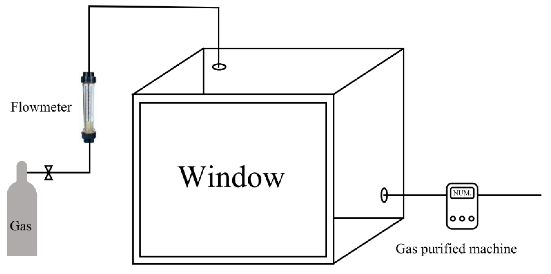
The acute toxic gas inhalation test device included an entirely closed 300 L exposure chamber with a visible window to observe the behaviors of the rats, two valves to control the flow of the experimental gas, a flowmeter to observe the administration rate, a pressure bottle to store the gas, a balance to determine the mass of the incoming gas, and a machine to purify the chamber after the test. The gas bottle was used in the weighing process. According to the weight change value and the volume of the chamber, the gas concentration was calculated. The volume of the test gas was relatively lower than the total volume of the 300 L chamber. Therefore, the change in gas pressure could be ignored. The outward gas valve was always closed when the gas was added to the chamber through another valve. It was closed until the concentration in the chamber reached the intended value, which could be found using the flowmeter and gas purified machine if a leakage situation appeared in the test. Usually, the process to reach the aimed concentration was not over 5 min. The concentration was kept stable owing to the air-tight seal of the chamber. The test apparatus was set up in an expertise room to ensure the correct oxygen content, temperature, and humidity. A concise drawing of the structure is shown in
Figure 1. A picture of the exposure chamber is shown in
Figure 2.
After lethal exposure, organ samples were taken and fixed with 4% paraformaldehyde. The samples were pruned, dehydrated, embedded, sliced, stained, and sealed according to standard pathology procedures. Then, the samples were examined using microscopy.
2.2. Analysis Equipment
The image acquisition instrument, including a positive white photo microscope, a positive polarized photo microscope, a positive fluorescence photo microscope, and a laser confocal microscope, was an Eclipse Ci-L (Nikon, Tokyo, Japan). The type of panoramic section scanner was PANNORAMIC DESK/MIDI/250/1000 (3DHISTECH, Budapest, Hungary). The scanning, browsing, and analysis software was Case Viewer 2.2 and Quant Center 2.1 (3DHISTECH, Budapest, Hungary). The picture analysis software was Image-Pro Plus 6.0 (Media Cybernetics, Rockville, MD, USA). The statistical and drawing software used was SPSS v20 (IBM, Armonk, NY, USA) and GraphPad Prism 5 (GraphPad Software, San Diego, CA, USA).
2.3. Test Method
Our previous work showed that a mixture of CF
3SO
2F/CO2 or CF
3SO
2F/N2 obtained satisfactory electrical performance and liquefaction when the CF
3SO
2F gas proportion was approximately 40~50% [
22]. However, this research only studied pure gas and did not discuss the toxicity of the mixtures, which could be calculated from the pure gas data.
The GHS (globally harmonized system) classification and definition of a chemical gas compound are currently based on the LC50 values from 4 h exposure tests. In China, the power industry created a standard “Biotoxication Test by Sulphur Hexafluoride” (DL/T 921-2005) to evaluate the toxicity of SF6 using a 24 h exposure test and a 72 h observation. The evaluation criteria were only suitable for SF6 and its mixtures because SF6 is extremely stable and only slightly toxic. Furthermore, during the exposure test, experimental phenomena, such as abnormal behaviors or death, were difficult to observe during a short-term test. Practically, there is still no international standard to evaluate the toxicity of SF6 replacements. The main reason for this is that studies of replacements have only recently come into focus, and perfect replacements have not yet been proposed. In addition, only properties such as toxicity are studied enough while workers dare to use the new gas. Compared with other new insulating gases, CF3SO2F has more positive values to be studied. Therefore, according to GHS, a 4 h acute toxic gas inhalation test was carried out to study the toxicity of pure CF3SO2F.
All parts of this experiment were completed in the Food and Drug Safety Evaluation Center of the Hubei Center for Disease Control and Prevention and complied with the center’s experimental protocol, amendments, and standard operating procedures (SOPs). Experimental protocols and amendments or procedures involving the management and use of animals were approved by the Animal Management and Use Committee of the Hubei Center for Disease Control and Prevention prior to commencement. The license number for laboratory animals was SYXK 2017-0065, and the experimental animal quality certificates were No. 42000600038239 and No. 42000600038360.
The test met the standard “Chemical toxicological evaluation procedures and test methods Acute inhalation toxicity test” (GBZ/T240.4-2011). All the test subjects were healthy SPF Kunming mice. The rats were selected for testing at age 5 or 6 weeks and weighed 18 to 22 g. Each cage contained five rats. The rats were free to eat and drink during the feeding period until the test started. Nutrients and environmental pollutants were regularly monitored during the feeding period; no known pollutants were found that might interfere with the experimental results or animal health. During the feeding period, the relative humidity was maintained at 40–70% and the temperature at 20–26 °C. The air exchange in the feeding room was >15 times/hour, and the light was cycled from bright to dark every 12 h. We estimated the toxicity on the basis of four 4 h acute inhalation toxicity test groups. The four groups were designed with increasing gas concentrations based on Horn’s method. The four concentrations were 10.0 g/m3 (1473 ppm), 21.5 g/m3 (3166 ppm), 46.4 g/m3 (6834 ppm), and 100.0 g/m3 (14,727 ppm). The molar concentrations were 0.0654 mol/m3, 0.141 mol/m3, 0.303 mol/m3, and 0.654 mol/m3. The gases in the exposure tests were static. The exposure chamber was kept strictly closed after the specified amount of gas was injected. After the animals died or the 4 h test period was complete, the valve was opened to release the gas, and the gas purification machine was used to recover the air in the chamber. The rats’ food and drinking water were continuously supplied to keep them active before the test started. The rats that did not die were moved to a feeding container for further observation until they died or fully recovered. The observation period was no more than two weeks. It was speculated that CF3SO2F gas would not cause lasting or continuous harm to these animals after two weeks.
The CF
3SO
2F gas was synthesized and supplied by our laboratory. The synthetic method and conditions were introduced in detail in our previous studies [
22,
23]. The synthetic route is shown in
Figure 3. The purity of the gas was >99.9%, as determined by gas chromatography–mass spectrometry (GC–MS). GC–MS was carried out on a Varian 450-GC gas chromatograph and a Varian 320-MS TQ mass spectrometer. The gas chromatograph was equipped with a 30 m × 0.250 mm, 0.25 mm df, VF-5 column. The final product was collected as a colorless liquid and stored in a pressure bottle. Before the exposure test started, the gas was passed into the chamber at its saturated vapor pressure. Test assistance was provided by the Hubei Provincial Academy of Preventive Medicine and Center for Disease Control and Prevention and the Serviebio Company.
In this paper, the sections were observed under a microscope using Case Viewer 2.2 software. Multiple tissue structures were observed. Obvious pathological changes and differences in the sections, such as inflammation, necrosis, degeneration, hyperplasia, and fibrosis, were described. Images of different typical lesion locations were captured by an imaging microscope using Case Viewer 2.2 software and indicated by colored arrows.
3. Results and Discussion
3.1. CF3SO2F Exposure Results
To investigate the toxicity of the new insulating gas CF
3SO
2F, 4 h inhalation tests were carried out. According to Horn’s method, four groups of rats were subjected to different gas concentrations. The molar concentrations were 1473 ppm, 3166 ppm, 6834 ppm, and 14,727 ppm. Each group included ten rats, with half being males and half being females. In the chamber, two cages were used to separate the sexes. The results of the tests are shown in
Table 2.
In the first group, all rats were active before the abnormal behavior appeared (see
Figure 4a). Several male rats became restless at 17 min. The main behaviors included hyperactivity, face rubbing, climbing the cage, and attempting to escape (see
Figure 4b). Then, the female rats exhibited similar symptoms. At 35 min, most rats switched to obvious distress, such as contracting in the corner of the cage (see
Figure 4c). However, at 1 h and 7 min, all rats started to be active again. It seemed that they were fully adapted to living with the CF
3SO
2F gas. No rats died in the first group, and the concentration was relatively safe. All rats eventually became normally active during the 14-day observation period, which confirmed that this concentration of CF
3SO
2F did not cause continuous harm.
In the second group, one male rat exhibited obvious tidal breathing at 3 min. Quickly, all male and female rats started to show signs of distress. Then, they struggled to breathe. One female rat died at 1 h and 11 min. In the end, two male rats and one female rat died (see
Figure 4d). In addition, there were two male rats in a state of near-death. In the observation period, all rats that did not die finally became normally active. This concentration was toxic enough to cause rats to die.
In the third group, the rats began to behave abnormally almost immediately after the test started. The abnormal behaviors of this group were more serious than those in the low-concentration group. Almost all rats showed significant convulsions, dyspnea, face rubbing, and other symptoms within a few minutes. The first male rat died at 45 min, and the others died after approximately 30 min. In the fourth group, all rats responded abnormally immediately after the gas was introduced into the chamber and died in a short time. Through Horn’s method, the calculated LC50 value for females was 27.1 g/m3 (3994 ppm), and the LC50 for males was 23.3 g/m3 (3434 ppm).
3.2. Pathological Section Analysis
To explore the effect of CF3SO2F on the organs and tissues of rats, pathological sections from dead rats exposed to different concentrations of CF3SO2F over 4 h acute inhalation tests were obtained and analyzed. Furthermore, pathological sections from rats that did not die were taken after two weeks of observation and analyzed, but there were no abnormalities in these samples. Therefore, these results are not discussed in this paper.
According to the pathological sections, there was little difference between the female and male rat samples. The main organs in the rat, such as the heart, liver, spleen, lungs, intestines, eyes, brain, and kidney, were observed and analyzed. After comparing the analyzed results, the heart, spleen, lungs, and eyes appeared to have suffered the most serious damage after exposure. Other organs also suffered different degrees of damage, but they were not obvious or serious.
The cardiomyocyte tissues were arranged regularly and stained uniformly. A large number of red blood cells and a small amount of brown-yellow pigment (see
Figure 5a, blue arrow) were observed in the chamber of the heart. A small number of inflammatory cells appeared (see
Figure 5a, yellow arrow), and inflammatory cell infiltration (see
Figure 5a, orange arrow) was observed in the surrounding tissues. More cardiomyocytes showed mild vacuolar degeneration with smaller round vacuoles (see
Figure 5c, black arrow) in the cytoplasm. The cytoplasm of many cardiomyocytes was loose and lightly stained (see
Figure 5c, red arrow), and a small number of lymphocytes were seen at the tissue edge (see
Figure 5b, green arrow).
The bronchial epithelial cells were irregularly arranged. A small number of bronchial epithelial cells were missing (see
Figure 6a, blue arrow) or shedding (see
Figure 6b, yellow arrow). Ecchymosis was widely shown (see
Figure 6b, yellow arrow). The alveolar walls were not significantly thickened. Congestion was observed in more blood vessels (see
Figure 6b, red arrow). Ectasia in the capillaries was shown in the alveolar walls (see
Figure 6c, black arrow). More eosinophilic filaments (see
Figure 6c, purple arrow) were observed in the alveoli with minimal inflammatory cell infiltration.
A small number of splenic nodules could be seen in the tissues, and their volume decreased. The red medullary cells were loosely arranged. Multinucleated giant cells (see
Figure 7a, blue arrow) and diffuse extramedullary hematopoietic cells (see
Figure 7b, red arrow) were observed. White and red pulp could be seen in tissues, and the boundary between the white and red pulp was unclear. The sizes of the white medulla were different. The white medulla lymphocytes and red medulla cells were loosely arranged.
Retinal detachment and uneven thickness were observed in the tissues. The nerve fiber layer was thickened (see
Figure 8a, orange arrow). A local inner plexiform layer thickening and inner granulosa cells could be seen in the layer of cells (see
Figure 8a, black arrow). A small amount of cytoplasmic vacuolization was observed in the ganglion cell layer (see
Figure 8a, yellow arrow). The cells in the inner and outer granular layers were loosely arranged. Numerous vacuoles were observed in the rods and cones (see
Figure 8a, red arrow). The anterior corneal epithelium was swollen, and the cytoplasm was loose and lightly stained (see
Figure 8b, blue arrow).
In summary, the main organs affected included the heart, lungs, spleen, and eyes. The typical pathological sections of these organs from the dead rat samples after exposure are shown in
Figure 5,
Figure 6,
Figure 7 and
Figure 8. The detailed pathological changes in the sections are indicated by arrows.
3.3. Discussion and Suggestions
As mentioned above, some vital organs were seriously damaged, such as the heart, eyes, etc., while other organs suffered less damage. Unfortunately, the mechanism of the damage process was unclear because of the lack of key property studies of this gas. However, the results could also provide effective protection suggestions for workers close to CF
3SO
2F. The tests found that the LC50 value for females was 27.1 g/m
3 (3994 ppm), and the LC50 value for males was 23.3 g/m
3 (3434 ppm). According to the GHS standard, this is level 4 toxicity. According to the WHO (World Health Organization) standards for the classification of acute toxicity of chemicals, the gas was recognized as a harmful compound (2000–20,000 ppm). Other standards classify this sort of gas as a low-toxicity compound. CF
3SO
2F is not considered an extremely toxic compound by any standard. Therefore, workers should be aware of this insulating gas but not overly afraid. Through different test methods, researchers also calculated the LC50 value of other mainstream insulating gases [
26]. The comparison of results is shown in
Table 3.
Common gas masks mainly include filter and isolation gas masks. On the basis of the results of the exposure tests and the analysis of the pathological sections in this paper, a filter gas mask is recommended. In addition, the analyzed results showed that the eyes could be seriously injured by CF3SO2F gas. The eyes require sufficient protection to avoid direct contact with the gas. A self-priming filter gas mask (full cover) could provide effective protection. Of course, the most important protection prevents workers from breathing large amounts of CF3SO2F gas. When a leakage accident occurs with electrical equipment using CF3SO2F as an insulating gas, the working environment should be in an open place or area with sufficient ventilation.


