Article

Development of a Cost-Based Design Model for Spread Footings in Cohesive Soils

by
Muhammad Muneeb Nawaz
1,
Shah Rukh Khan
1,
Rashid Farooq
1,
Muhammad Naqeeb Nawaz
2,
Jamil Khan
1,
Muhammad Atiq Ur Rehman Tariq
3,4,
Rana Faisal Tufail
5,
Danish Farooq
5 and
Anne W. M. Ng
6,7,*
1
Department of Civil Engineering, Faculty of Engineering and Technology, International Islamic University, Islamabad 44000, Pakistan
2
Institute of Civil Engineering, National University of Sciences and Technology (NUST), Islamabad 44000, Pakistan
3
College of Engineering and Science, Victoria University, Melbourne, VIC 8001, Australia
4
Institute for Sustainable Industries & Liveable Cities, Victoria University, Melbourne, VIC 8001, Australia
5
Civil Engineering Department, COMSATS University Islamabad, Wah Campus, Wah 47040, Pakistan
6
College of Engineering, IT & Environment, Charles Darwin University, Darwin, Ellengowan Dr, Brinkin, NT 0810, Australia
7
Energy and Resources Institute, Charles Darwin University, Darwin, Ellengowan Dr, Brinkin, NT 0810, Australia
*
Author to whom correspondence should be addressed.
Sustainability 2022, 14(9), 5699; https://doi.org/10.3390/su14095699
Submission received: 1 March 2022 / Revised: 1 May 2022 / Accepted: 4 May 2022 / Published: 9 May 2022
(This article belongs to the Special Issue Studies on Sustainable Rehabilitation of the Built Environment)

Abstract

:
The use of cost-effective construction design approaches is an emerging concept in the field of sustainable environments. The design of the foundation for the construction of any infrastructure-related building entails three basic requirements, i.e., serviceability limit state (SLS), ultimate limit state (ULS), and economics. Engineering economy coupled with safety are the two main essentials for a successful construction project. The conventional design approaches are based on hit and trial methods to approach cost-effective design. Additionally, safety requirements are prioritized over the economic aspect of foundation design and do not consider safety requirements and cost simultaneously. This study presents a design approach that considers foundation construction costs while satisfying all the technical requirements of a shallow foundation design. This approach is called an optimization process in which the cost-based isolated foundation design charts were developed based on the field SPT N data. The design charts are the first of their kind for the robust design of foundations and can be used to compare the economic impact of different bearing capacity models. Furthermore, the design framework considers the quantitative impact of the different applied factors of safety values in terms of cost. The results show that Vesic’s equation yields higher values of bearing capacities than Terzaghi and Meyerhof. On the other hand, Vesic’s theory offers a 37.5% reduction in cost as compared to the conventional design approach of the foundation for isolated footing.

1. Introduction

Cost-effective infrastructure development techniques are the pertinent components of a sustainable environment. Therefore, construction techniques or frameworks with the least construction cost without detriment of the safety requirements or the major millennium development goals in the field of infrastructure development as the cost is one of the core indices of sustainability [1]. Hence, researchers are striving to explore modern techniques to ensure the sustainability of the environment. This study presents the cost-based design charts for the construction of the foundation for any infrastructure development purpose.
The three fundamental requirements of foundation design involve serviceability limit state (SLS), ultimate limit state (ULS), and economics. The serviceability limit state defines/verifies that the designed footing should not exceed the limits of allowable settlement, while the ultimate limit state defines/verifies that the resistance of soil (bearing capacity) should be greater than the load of the building while satisfying safety criteria of design. However, many design engineers completely ignore the economic aspect of the structure which costs a lot [2]. The economics along with the safety must be considered prior to the structural design of the foundation. There are various design techniques that can satisfy limit state design (LSD) requirements, but the final design is governed by the design with the least construction cost. As stated by Wellington, “an engineer’s job is to do a work with one dollar as a bungler can do in two or more” [3,4].
A shallow foundation design is a procedure to specify the dimensions and materials of the foundation following the safety requirements based on subsurface soil conditions. The most economical design is the one with the design parameters satisfying the minimum ULS and SLS requirements and consequently yielding the minimum construction cost. A conventional design must justify the minimum ULS and SLS requirements. ULS is the function of applied load and bearing capacity of the soil, while SLS is governed by the potential of soil to settle within the allowable ranges under the bearing loads. For safe and accurate foundation design, the estimation of the bearing capacity requires special considerations because the inaccurate assessment of the bearing capacity of soil can drastically affect the economics of structure and have serious consequences. Geotechnical foundation design involves field investigations and laboratory tests. Traditional and general practices of bearing capacity determination mainly focus upon limited soil parameters, which impacts the economic point of view of the structure [5]. Over-predicted bearing capacity can also affect the timeline of the project by increasing the work [2]. The use of the higher factor of safety (FoS) for foundation design is a general practice in conventional design methods. Conventional shallow foundation design practices involve conservative approaches and are more inclined to fulfillment of safety requirements while economics is ignored. According to Wellington, the father of the engineering economy, the secret to the success of a construction project lies in the cost-effectiveness of the project. Traditional design practices are based on hit-and-trial methods. The conventional design practices involve high FoS i.e., 4, least BC value from four equations (Terzaghi, Meyerhof, and Vesic), lowest SPT N value for design, and mostly c = 0 approach for cohesive soils. Thus, conservative approaches without following any definite guidelines tend to increase the cost of the project and are time-consuming as well. Therefore, there is a need to develop an efficient technique that considers safety requirements and economics altogether. This approach, however, makes a design safe but depicts a lack of confidence and increased construction cost.

2. Literature Review

Azhim et al. [6] worked on the optimization of sandy soils of Indonesia using the Excel Solver technique. However, the proposed model is not valid for cohesive soils. Chaudhri et al. [7] presented the optimization models of isolated footing-based genetic algorithms and unified particle swarm theory using MATLAB tool. However, the proposed optimization methods deal with the structural aspects of isolated footing only and do not consider the subsurface conditions and geotechnical design of the foundation. Juang et al. [8] proposed the reliability-based robust geotechnical design optimization of spread footing. Rawat et al. [9] presented the technique for the optimization of reinforced isolated footing. The optimization technique does not involve the geotechnical aspect of isolated foundation design. Islam et al. [10] worked on the optimization of shallow foundations using a genetic algorithm. This technique involves the geotechnical design aspects for the optimization of shallow foundations. Wang [11] worked on the reliability-based design optimization of shallow foundations. Wang et al. [12] presented an optimization model for spread footing in sandy soils. The model does not consider the cohesive nature of soils and the water table effect. Kashani et al. [13] presented the evolutionary algorithm for the optimization of shallow foundations. This study focuses on structural aspects of the foundation by considering the effect of variation in the position of the column on top of the foundation. Khalid et al. [14] presented the qualitative charts based on SPT N data and USCS-based soil type for Islamabad soil. Luat et al. [15] presented an optimization approach for the prediction of settlement in sandy soils. Rabiei et al. [16] worked on the economic optimization of piled raft foundations considering the safety requirements. Fathima Sana et al. [17] proposed a reliability-based approach for the optimization of shallow foundation design in sandy soils using surrogate numerical modeling. Zhong et al. [18] presented the robust design approach for spread footing considering the multiple failure modes of foundation. Moayedi et al. [19] worked on the optimization of the bearing capacity of shallow foundations based on the water-cycle error minimization technique. Jaafar et al. [20] proposed a multi-objective optimization algorithm for machinery allocation in shallow foundations. Kashani et al. [13] presented the cost optimization technique for shallow foundation design using evolutionary algorithms. Hence, all the optimization techniques presented in the literature are either difficult to implement in the field or focus on the specific structural aspect of design or geotechnical aspect of the design of the foundation.

2.1. Research Gap

Conventional foundation design practices are based on the trial-and-error method, which is time-consuming. Additionally, existing economical optimization-based approaches are either difficult to implement in the field by design engineers or are more centered on safety rather than considering cost and safety simultaneously. Furthermore, there is limited work on foundation design algorithms that consider cost and geotechnical design integrated with the structural design of the foundation. Hence, there is a need for a design procedure that is efficient and considers safety requirements along with the economics. Thus, the current study focuses to develop a novel costs-based framework for the design of the shallow foundations using field SPT data for the Silty clayey soils. The framework distinguishes the economic effect of various FoS values with different bearing capacity models in quantitative terms. Field data were used to develop an efficient and quick design methodology. Finally, the design charts were developed which are the first of their kind and are robust in nature for the design and cost analysis of the foundation.

2.2. Aim and Objectives of the Study

This study aims to develop an innovative optimization framework for the cost-based design of isolated foundations in cohesive soils using field SPT data. The primary objectives of the study are
  • To present an optimized model comprising of cost-based foundation design charts which consider safety requirements, i.e., ultimate limit state (ULS) and serviceability limit state (SLS), along with the economy of the design project.
  • To clarify the flaws in usual practices adopted to estimate bearing capacity by analyzing different case studies.
  • To analyze cost estimation and to compare the economic effect while considering the variability of BC values.

3. Development of Conceptual Framework

Whenever a new construction project is being planned, it is extremely important to study the physical characteristics of the proposed site. These physical characteristics include the geotechnical and geological properties of the region. We must strive to produce designs that are both safe and cost effective. Achieving the optimum balance between reliability (safety) and cost is a part of good engineering. According to Terzaghi, the foundation is shallow if the depth of the footing is less than or equal to the width of footing, but later for a shallow foundation, the depth divided by the width of footing should be less than or equal to 4 [6].
While designing a shallow foundation, there are various bearing capacity equations that yield different bearing capacity values. The selection of an appropriate bearing capacity equation for design is the key parameter governing the economics of the foundation. The higher bearing capacity value yields a lower construction cost [21]. To formulate the concept of obtaining the most economical foundation design, an approach was developed for cohesive soils (ø = 0) [4], in which the bearing capacity of soil from the same site was determined using three different bearing capacity equations, i.e., Terzaghi, Meyerhof, and Vesic. The safety and economic aspects were measured and compared for the highest and lowest values amongst the three bearing capacity values. If the highest bearing capacity value satisfies the safety criteria, this can be treated as the governing bearing capacity value for foundation design. Keeping in mind the underlined concept, a design philosophy for shallow foundation design in Silty soils was developed. This is illustrated by the case studies and real-time data from the Silty Soil. ETABS is commercial software that is used for the structural design of buildings. SAFE is another software that can be used for the structural design of the foundation. As the cost of the foundation is related to five activities involved in the construction of the foundation namely excavation, concrete, backfill, and reinforcement. These are related to the designed parameters of the foundation, i.e., width (B), length (L), and embedment depth (Df). PLAXIS 2D is a finite element analysis tool and can be used to obtain the settlement of the foundation. In general, different numerical analysis tools were adopted for the scope of this study to obtain the foundation design charts which can be effectively used to obtain foundation design parameters that yield the lowest construction cost.
The output of this method was in the form of considerable cost optimization while keeping in view the safety standards of Building (ACI) [22,23]. The geotechnical design of a shallow foundation involves the bearing capacity determination of soil underneath the foundation. There are numerous bearing capacity equations given by various authors. Every equation gives a different value from the other. The most frequently used equations are Terzaghi [24], Meyerhof [25], and Vesic [26] in Islamabad Pakistan [5]. Figure 1 explains the framework for the economical optimized design of isolated foundations.

3.1. Data Collection

Data collection is the most crucial step in order to develop a design framework and its validation. Data for this research were taken from 25 different soil investigation reports of Islamabad, Pakistan. Geologically, the formation of the study area consists of low plastic clay, shale, siltstone, mudstone, and sandstone type of strata. In general, low plastic clay (CL) and silty clay (CL-ML) are encountered at shallow depths in this area. A soil investigation report contains all the relevant information needed for the design of foundation, retaining structures, etc. The foundation design parameters, i.e., SPT N value, unit weight of soil, and undrained shear strength (for a fine type of soil), were deduced from the reports in order to develop the economical shallow foundation design framework.

3.2. Bearing Capacity Calculations and Foundation Design

The design of a foundation is the process of specifying the dimensions and materials of the foundation. The size (width, length, and depth) are the design variables of foundation design. ULS and SLS are the two criteria of safety that can be defined using Equations (1) and (2) [12].
FS r = q ult F / BL   3
( SLS ) Δ < 0.08   ft   ( 25   mm )
where qult (psf) is the ultimate bearing capacity of the soil, F (kips) is the applied vertical building load, B (ft) and L (ft) is the width and length of the foundation, and (SLS)Δ is the settlement that was estimated using PLAXIS 2D.
The design variables of the foundation are functions of soil strength (bearing capacity) and its capability to undergo settlement are specified, considering the strength and settlement criteria. The bearing capacity of soil can be determined using various bearing capacity models. In this study, bearing capacity models presented by Terzaghi, Meyerhof, and Vesic’s were used to evaluate the bearing capacity of soils. The comparison of different bearing capacity models is also carried out to propose an economical and safe solution.

3.2.1. Correlations between N-Value and Su

The data obtained from site investigations were based on limited soil properties and design parameters. Hence, correlations were developed by the researchers to facilitate the design procedure using the limited soil properties. Figure 2 shows the dominant soil type as Silty Clay. Therefore, a correlation of SPT-N and undrained shear strength (su) (kPa) was used to determine undrained shear strength. Equation (3). [27,28] is used to determine (su) from SPT N values. The bearing capacity of the fine type of soil is a function of undrained shear strength as the friction angle (phi) is zero. The undrained condition exists in saturated clayey soil when subjected to loading in a short time interval. This is due to the reason that clayey soils have very low permeability and such type of soils do not permit water to dissipate under quick loading [29,30,31]. Thus, particle to particle interaction vanished due to an increase in pore pressure upon loading in undrained conditions. Hence, phi zero condition was developed.
S u = 10 × ( SPT   N   value ) × 20.89   ( psf )

3.2.2. Bearing Capacity Equations

The bearing capacity model presented by Terzaghi [24] is given in Equation (4). Terzaghi was the first one to present ] the concept of analytical determination of bearing capacity based on limit equilibrium methods.
Q u = 1.3   c   N c +   γ   D   N q + 0.4   γ   B   N γ  
where, c (psf) = cohesion of soils, φ = angle of internal friction, γ (pcf) = unit weight of soils, D (ft) = Depth of footing, B (ft) = Width of footing, Nc, Nq, Nγ can be found out using equations given below.
N c = ( N q 1 ) cot ( φ )  
N q = tan pi * tan ( φ )   tan 2 ( 45 + ( φ 2 )   )    
N γ = ( N q 1 ) tan ( 1.4 φ )  
Meyerhof [25] extended the bearing capacity model of Terzaghi by incorporating the effect of shape factors. The bearing capacity model of Meyerhof is considered to be more accurate and detailed as compared to Terzaghi bearing capacity model. The equation of Meyerhof bearing capacity is given below;
Q b =   c   N c   S c   d c +   q o   N q   S q   d q + 0.5   g   B   N γ   S γ   d γ
where,
N q = tan 2 ( 45 + φ 2 ) e π   tan   φ
N c =   cot   φ   ( N q     1 )
N γ   = 2   ( N q + 1 )   tan   φ
Vesic [26] further extended the Terzaghi and Meyerhof equation by incorporating depth, shape, and inclination factors. The equation is given below.
q u =   c   N c S c d c i c b c + σ zD N q s q d q i q b q + 1 2   γ   BN γ s γ d γ i γ b γ
where, Sc, Sq, Sγ are shape factors, dc, dq, dγ are depth factors, ic, iq, iγ are inclination factors, bc, bq, bγ are base inclination factors, and k is the coefficient of lateral earth pressure. Inclination factors are equal to 1 due to the concentric nature of the foundation. Other factors are given below.
S c = 1 + ( B L ) ( N q N c )
S q = 1 + ( B L ) tan   Φ
S γ = 1 0.4 ( B L )
d c = 1 + 0.4 k
d q = 1 + 2 k   tan   Φ ( 1 sin   Φ ) 2
d γ = 1

3.3. Calibration of Factor of Safety for Design

The factor of safety in any design is applied in order to cater to the uncertainties and errors involved in the execution of the construction project [32,33]. In geotechnical engineering design, the FoS is applied to find out the allowable FoS that can be used for design purposes [29,34]. However, the proper use of FoS requires experience and state-of-the-art knowledge. Otherwise, excessive use of FoS values may lead to uneconomical conditions. Therefore, it is pertinent to consider the effective use of the proper FoS values for an economical design. Literature suggests the various factor safety values for geotechnical design of shallow foundations based on the nature of the project, groundwater conditions, and various soil types. However, quantitative assessment of economics due to various factors of safety values is yet to be explored. This study aims to establish the design charts for shallow foundation design in silty clayey soil which not only incorporate safety requirements but also dictate the economics as well. Conventional design practices involve the use of excessive FoS. For example, FoS of 4 is usually used for design purposes in Islamabad. In this study, economic design charts were developed for different factors of safety values (i.e., 4.0, 3.5, 3.0) using three bearing capacity models based on generalized loading and sub-surface conditions of Islamabad.

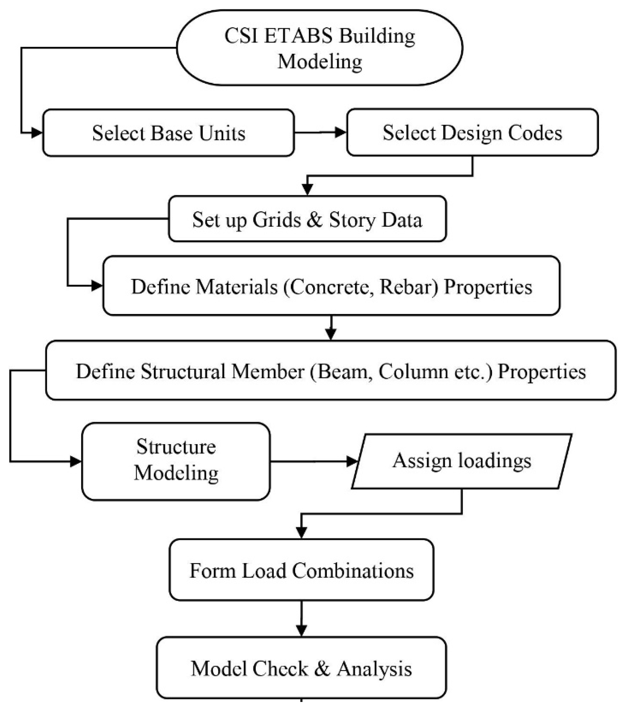
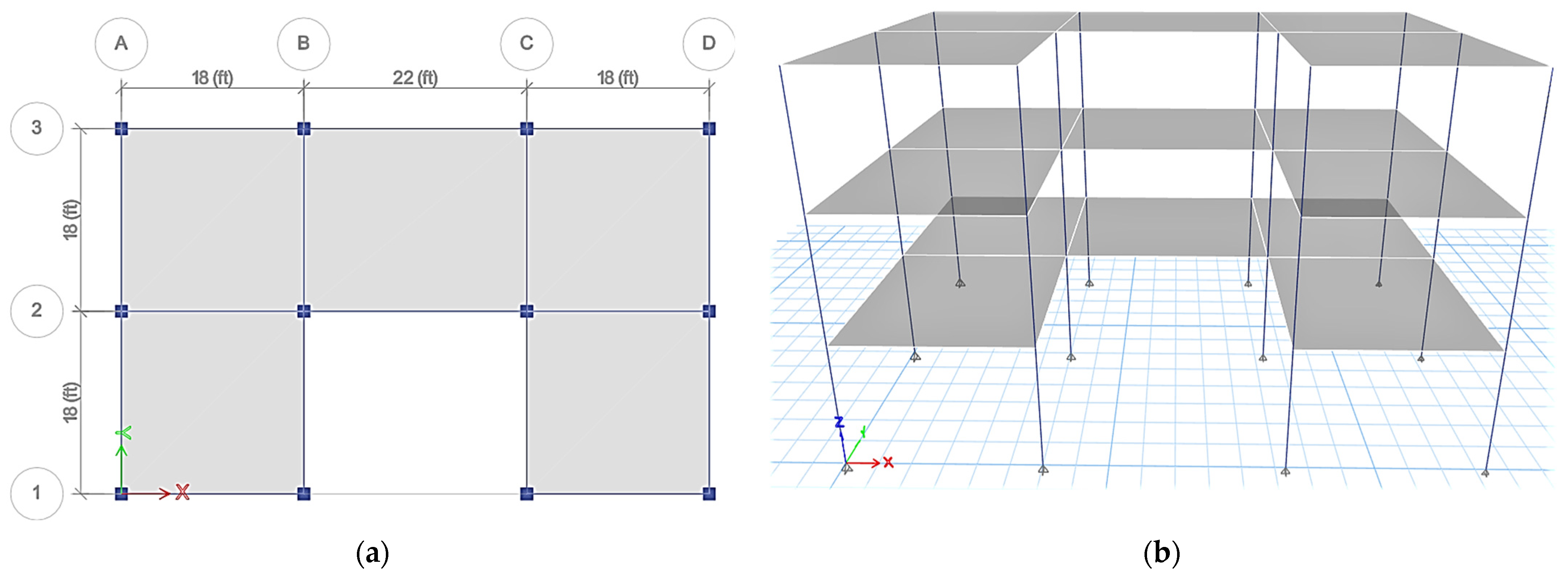
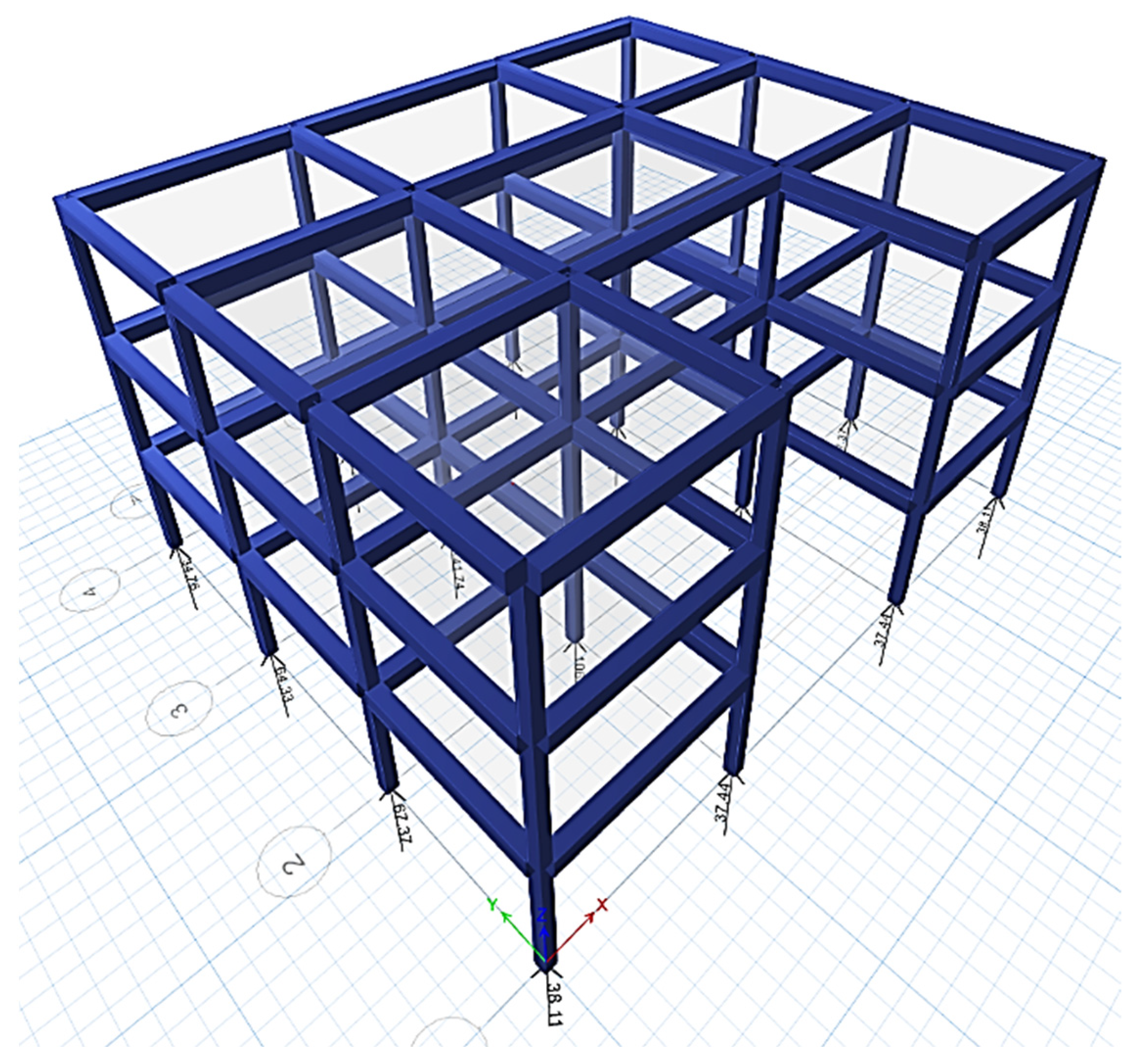
3.4. CSI ETABS Modeling

E-TABS is one of the most used commercial software for the structural design and analysis of buildings. The generalized design procedure in ETABS is given in Figure 2 [35].
In this research, an office building located (3 stories) in Islamabad was considered as a case study. The office building is designed according to the American Concrete Institute (ACI) 318 and the Building Code of Pakistan. E-TABS provides expected imposed loadings and base moments on the soil foundations. Table 1 provides the details of materials, e.g., concrete and reinforcement (rebar) specifications for the building design according to the different sections, while Table 2 provides the details regarding the section properties of the structural members of the building.
The building load and base moments were used for the structural design of the foundation, which in turn govern the economics of the foundation. A critical column with maximum load was selected for the structural design of the foundation in accordance with ACI Code provisions. The plan and building model are elaborated in Figure 3. According to LSD (Limit State Design) criteria of Reaction forces (B.C) < Action forces (loads). The area of the designed building is 65.5 ft × 55.5 ft (3635.25 square ft). The designed building is a three-story building with floor heights of 12 ft.

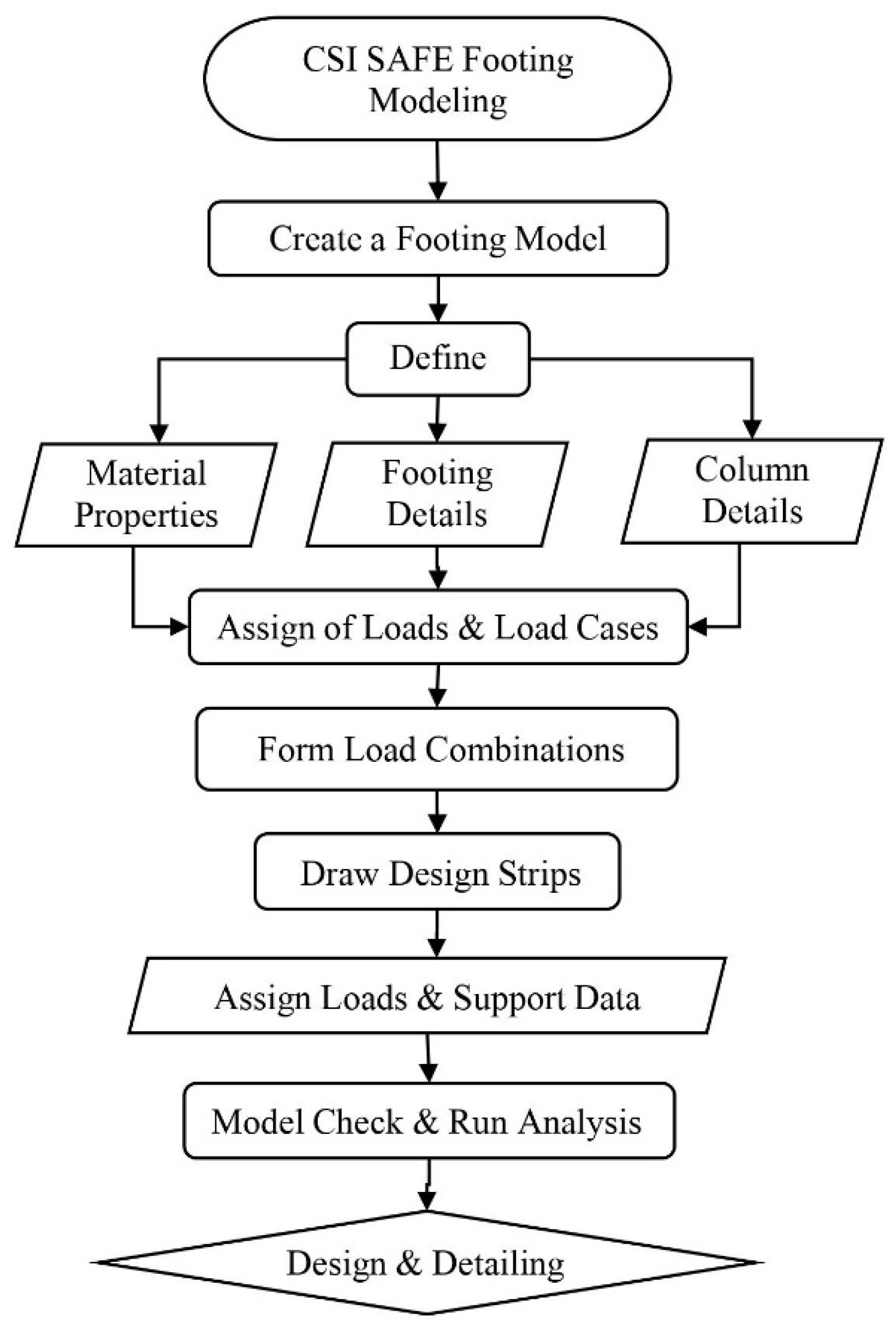
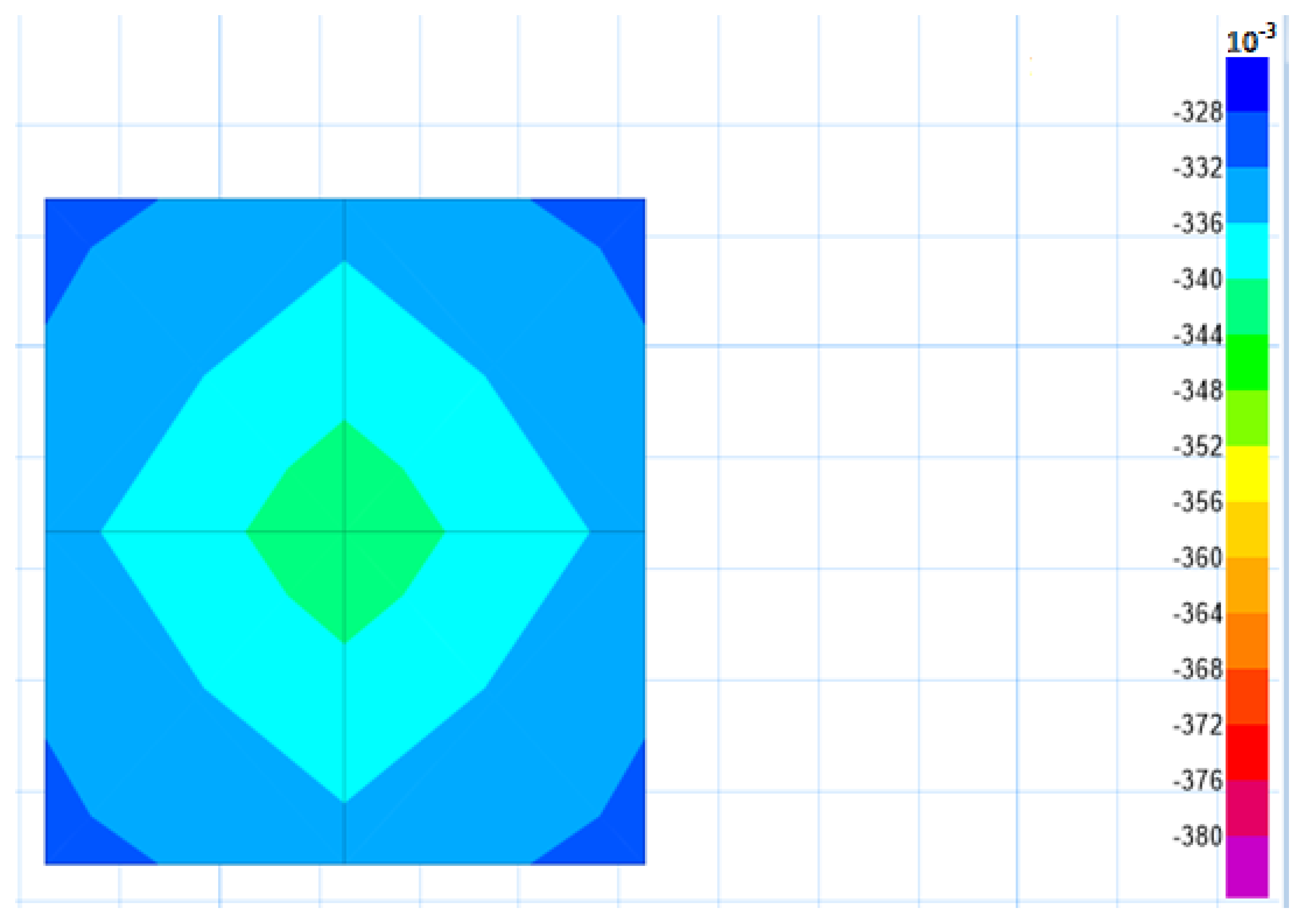
3.5. CSI SAFE Modeling

CSI SAFE [36] is software used for the analysis and design of the foundation. The structural design of the foundation is a procedure to specify actual dimensions and reinforcement details against safety requirements under the critical building column load and base moments. The structural design of the foundation using SAFE software is primarily based on allowable soil bearing capacity and load transmitted to the soil by the critical column. The generalized design procedure is illustrated in Figure 4.
In this study, bearing capacities calculated from three equations with a different FoS are used for a critical loaded column of the building which was designed in E-TABs. Different bearing capacity values will provide different designs for the same loading. CSI SAFE provides area (width) and area of steel for footing which is required for further cost estimation analysis. Figure 5 shows the foundation design model in SAFE software.

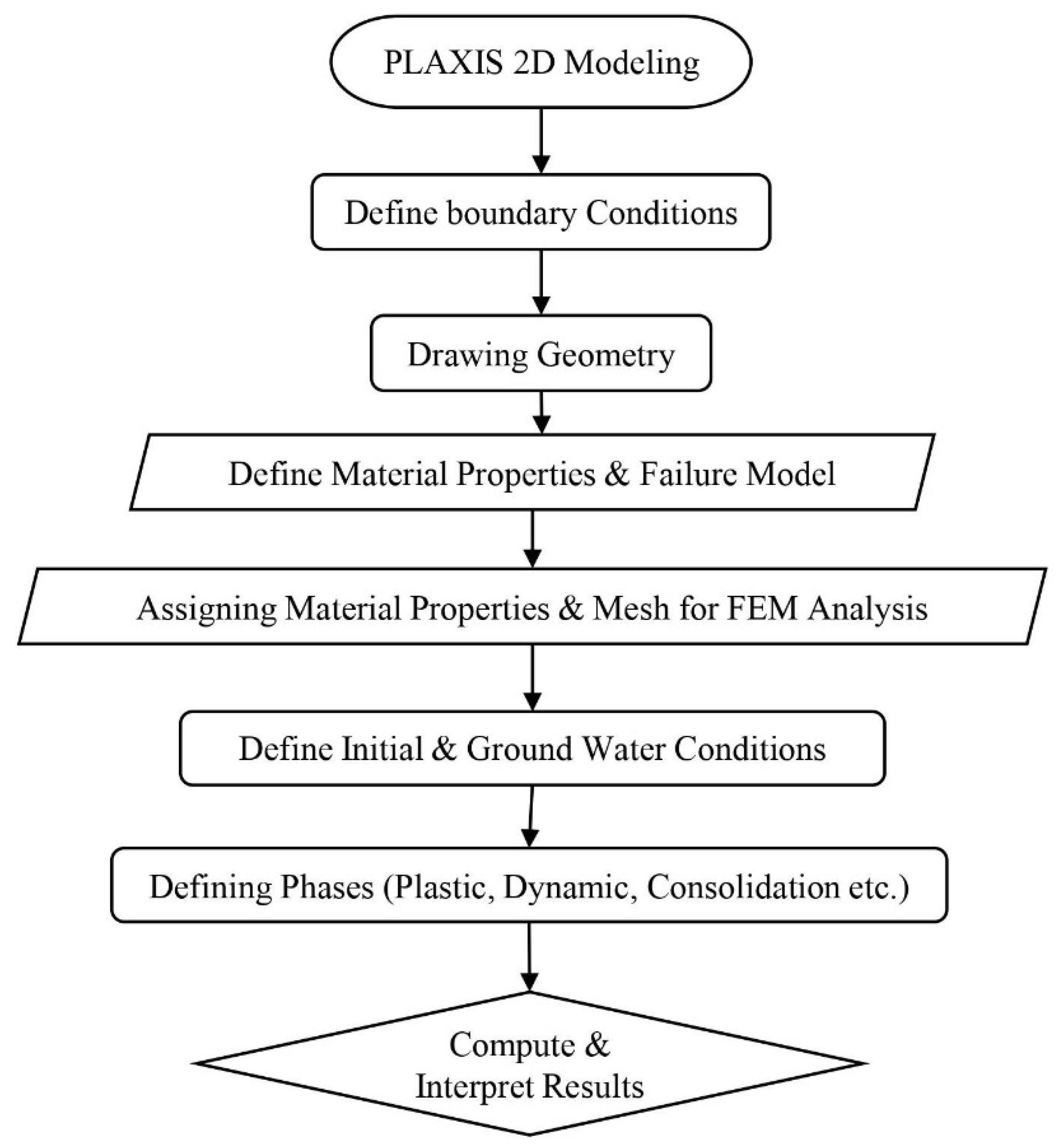
3.6. PLAXIS 2D Modeling

In the next step, PLAXIS 2D [37] is used for serviceability limit state (SLS) design. PLAXIS 2D software is used to check the safety of soil under building loads. The prescribed displacement method is used for SLS design. The generalized design procedure is illustrated in Figure 6.
This method consists of modeling actual site conditions using soil properties (such as sat. unit weight, elastic modulus, cohesion, and SPT N values) and footing details (obtained from CSI SAFE) in PLAXIS 2D. This method provides maximum loading for a prescribed displacement (25 mm). The obtained loading is confirmed with the designed loading. The obtained loading from PLAXIS 2D should be less than the designed loading. Figure 7 presents an illustration using PLAXIS 2D software for simulating the model of the site at which the structure will be constructed.

3.7. Cost Estimation Analysis

Cost Estimation analysis of footing is carried out based on structural design obtained from CSI SAFE to compare the cost of the different bearing capacity values. Cost estimation was carried out using composite schedule rates (CSR) of the National Highway Authority (NHA) [38] and Punjab Work Department (PWD). Equation (19) was used to estimate the construction cost of the foundation [12].
Construction   Cost   ( C ) =   Q e   R e +   Q f   R f +   Q c   R c +   Q r   R r +   Q b   R b
where Re, Rf, Rc, Rc, Rb are unit rates for excavation, formwork, concrete, reinforcement, and compacted backfill, respectively, which can be calculated using Equations (20)–(24). The unit prices for shallow foundation construction are summarized in Table 3.
Q e = ( B + B o ) ( L + L o ) D f
here, B (m), L (m), and Df (m) are the width, length, and depth of the foundation, respectively, while Lo and Bo are over-excavation distances, respectively. Bo and Lo can be taken as 0.3 [39]. The quantity of formwork (Qf) can be calculated by Equation (21). For the concrete quantity width of footing (B), length (L), and thickness (T) are multiplied. From Equation (23), the quantity of concrete was determined by multiplying the unit weight of the bar (γRebar) with the width of footing (B), along with the total number of bars required for the footing. The quantity of the backfill after construction is determined from Equation (24) by subtracting the quantity of concrete (Qc) from the excavation quantity (Qe).
Q f = 2 T   ( B   +   L )
Q c =   BLT
Q r = γ Rebar   B   ( total   No .   of   Rebars )
Q b =   Q e     Q c
In this study, the cost is calculated in the currency of Pakistan, the Pakistani Rupee (PKR). The unit prices are taken from the schedule rates of NHA (National Highway Authority Composite Schedule rates (Punjab), 2014). The unit prices for shallow foundation construction are summarized in Table 3.

4. Results

4.1. Results from CSI ETABS

Figure 8 shows the analyzed and designed 3D model of the building according to the Building Code of Pakistan, American Concrete Institute (ACI) 318-2014, and Uniform Building Codes (UBC) 97 to obtain the service load for the critical column among all the columns. The building was modeled using the input parameters and specifications described in Section 3.5. The isolated foundation was designed against the critical loaded column, which is a conservative conventional practice used by the design engineers. In this study, a similar approach was utilized to obtain the critical column load. During the analysis, it was observed that Columns C6, C7, C10, and C11 carry maximum but same loading. These four columns carry a total of 215.15 kips individually.

4.2. Results from CSI SAFE

Results (column load) obtained from CSI ETABS and bearing capacity equation were used in CSI SAFE software for footing design. Figure 9 shows the results of footing designed based on input parameters of loading and soil properties. This software analysis provides the required area of foundation and reinforcement details for structural design purposes. The footing was modeled against the critical column load obtained from the output of the ETABS building model and computed bearing capacity values. The structural design of footing involves the determination of reinforcement (area of steel, As) based on actual footing width, i.e., Bactual. The reader is referred to Bowl’s book [31] for the details regarding the structural design of the footing.

4.3. Results from PLAXIS-2D

A footing should not undergo beyond the allowable settlement limits while successfully carrying loadings from the structure. This settlement analysis was performed in PLAXIS-2D software. PLAXIS-2D results show that the soils can bear the 570 kips of stress against prescribed settlement criteria of 0.08 ft (25 mm) as shown in Figure 10.

4.4. Bearing Capacities of Selected Sites

The bearing capacity was determined using an average of SPT N values from the influence zone for 25 different sites in Islamabad. The SPT N values used for the design purpose are referred to as NDesign, which is given by Equation (25) [28], where Ni represents the corrected SPT N value at each layer and I represent the number of layers at which SPT N values are available from footing base to influence zone of the footing. The bearing capacity was determined using three bearing capacity equations, i.e., Terzaghi, Meyerhof, and Vesic.
N Design = i = 1 n N i i 2 i = 1 n 1 i 2

4.5. Design Charts

Following design, charts provide an estimated design of shallow foundation with the use of an appropriate FoS even with the non-availability of enough data. The design charts are also useful in designing a cost-effective shallow foundation considering safety requirements.

4.5.1. Design Charts Based upon Terzaghi’s Equation

Figure 11 represents the design charts based on Terzaghi’s bearing capacity model for different FoS values. The design charts were developed to design an isolated foundation in a quick manner. Figure 11a presents the direct relation between the SPT NDesign value and ultimate bearing capacity determined from Terzaghi’s equation, with the increase in NDesign value the ultimate bearing capacity also increased mainly due to the increase in stiffness of the soil. Likewise, in Figure 11b, the relation between ultimate bearing capacity and the actual width of the foundation was developed. It contains three trendlines for the allowable bearing capacity at the different factors of safety. The higher the FoS, the higher will be the BActual, and the more conservative will be the approach for design. These trends decrease exponentially due to the enhancement of the soil properties, thereby increasing the ultimate bearing capacity. Figure 11c shows the relation between the actual width of footing and the required area of steel. It shows that the requirement for the area of the steel increases with the change in footing size. Bearing capacities of different FoS show a similar trend due to the minimum reinforcement criteria of the ACI-318 for the footing design. Figure 11d shows the relation between the actual width of footing and the amount of settlement calculated through the PLAXIS 2D software. This trend shows the increase in immediate settlement with the increase in the size of footing, while Figure 11e represents the estimated cost against the ultimate bearing capacity for different FoS values. It provides a quick total cost estimation for the footing including the material and labor costing. These charts can be used in steps to design an economical foundation in a sequence from part (a) to (e). For example, these design charts can be used in a way that once NDesign is selected, ultimate bearing capacity is then determined using the procedure enlisted above. Then design chart (b) is used to find out the actual width of the footing. Then chart (c) is used to interpret the actual reinforcement details. Then, chart (d) is used to calculate the amount of settlement corresponding to the size of the footing and then compare it with the permissible limits. Finally, the economics of the designed foundation can be analyzed using the chart (e) based on different FoS values. Hence, optimized design is obtained quickly. It is worthwhile to mention that BActual is the actual width of footing that is computed during the structural design of footing and it must not be confused with “B,” which is the assumed value of width used for the determination of bearing capacity during the geotechnical design of footing.

4.5.2. Design Charts Based upon Meyerhof’s Equation

The design charts based on Meyerhof bearing capacity model were prepared similarly, as explained in Section 4.5.1. These charts show a similar trend, as we have seen in the charts of Terzaghi’s equation in Section 4.5.1. However, Figure 12a presents the direct relation between the SPT NDesign value and ultimate bearing capacity determined from Meyerhof’s equation. Figure 12b represents the relation between ultimate bearing capacity and the actual width of the foundation. These trends also decrease exponentially with the increase in ultimate bearing capacity. Figure 12c shows the relation between the actual width of footing and the required area of steel. These trends increase with the surge in footing size. Lines also show a similar trend due to the minimum reinforcement criteria of the ACI-318 for the footing design. Figure 12d presents a correlation between the actual width of footing and the amount of settlement calculated through the PLAXIS 2D software. This shows immediate settlement increases with the increase in the size of the footing. Figure 12e presents a correlation of the cost of footing with the ultimate bearing capacity of the soil. Poor soil properties affect the bearing capacity, which causes an increment in the economics.

4.5.3. Design Charts Based upon Vesic’s Equation

The design charts based on the Vesic bearing capacity model were prepared in a similar way, as explained in Section 4.5.1. The behavior of these charts shows exact similar trends, as we have witnessed for the other equations model charts. However, the results obtained from Vesic’s model indicate that it provides the most economical and safe solution for the foundation design. Figure 13a presents the direct relation between the SPT NDesign value and ultimate bearing capacity determined from Vesic’s equation. Figure 13b represents the relation between ultimate bearing capacity and the actual width of the foundation. Figure 13c shows the relation between the actual width of footing and the required area of steel. Moreover, in this model, the minimum reinforcement criteria of the ACI-318 for the footing design governs causing approximately a similar trend for different bearing capacities. Figure 13d presents the correlation between immediate settlement and actual width of footing using PLAXIS 2D modeling. This trend shows the increase in immediate settlement with the increase in the size of the footing. Figure 13e presents a correlation of the cost of footing with the ultimate bearing capacity of the soil.

5. Discussion

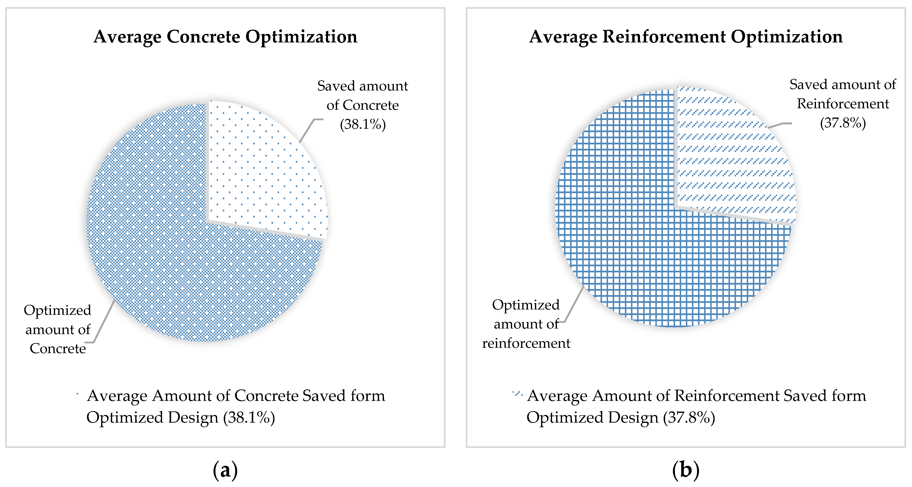
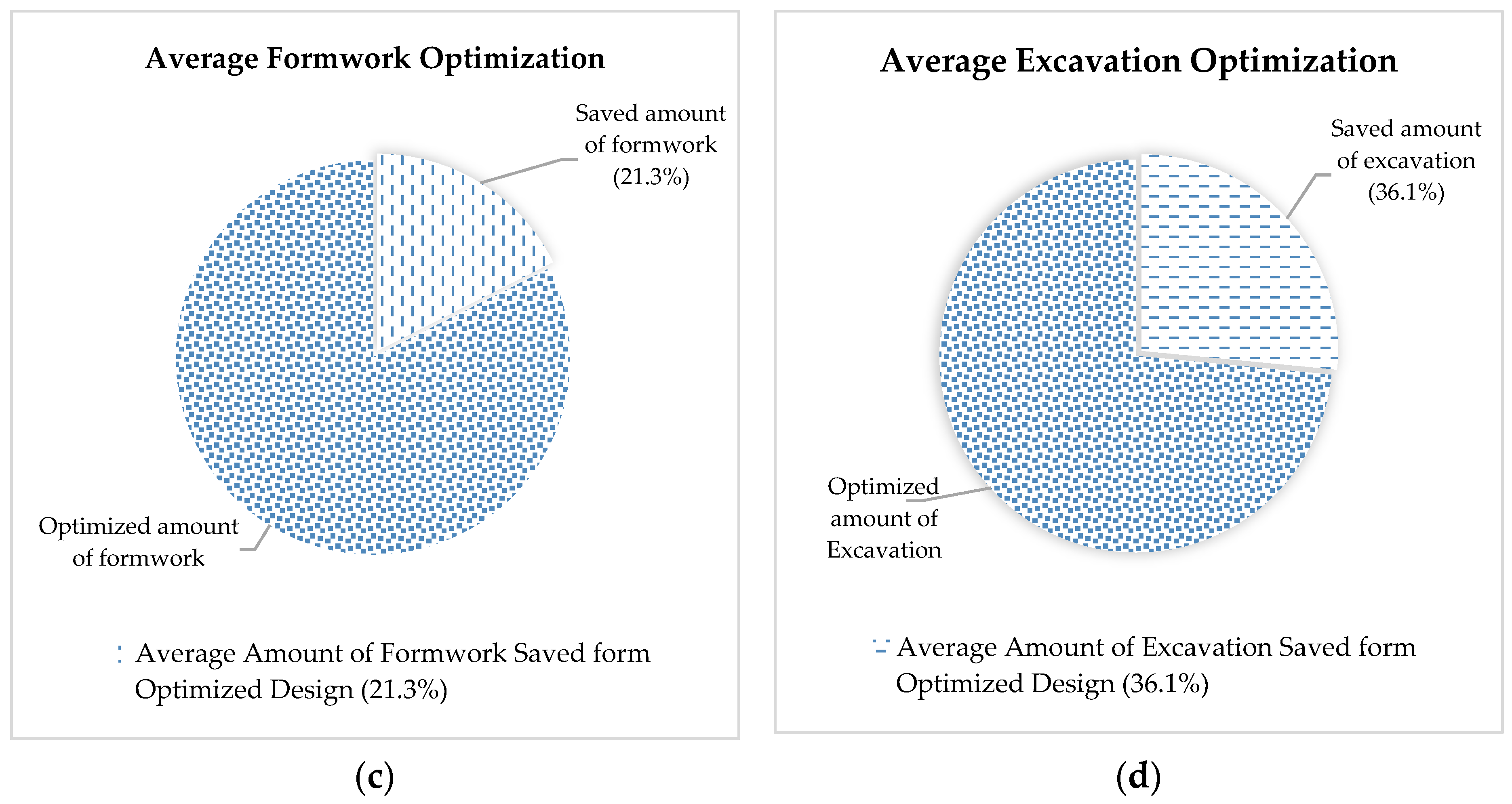
5.1. Optimization of Foundation Material

Using the optimized model, plenty of material can be saved, which ultimately results in improving the economics of the design. Thus, Figure 14 illustrates a comparative analysis of the material used for the optimized model approach and conventional design procedures. The amount of concrete majorly impacts the cost of a foundation. The optimized design approach can result in a 38% reduction in concrete material and 37.8%, 21.3%, and 36.1% in reinforcement, formwork, and excavation, respectively, which in turn affect the cost of the foundation.

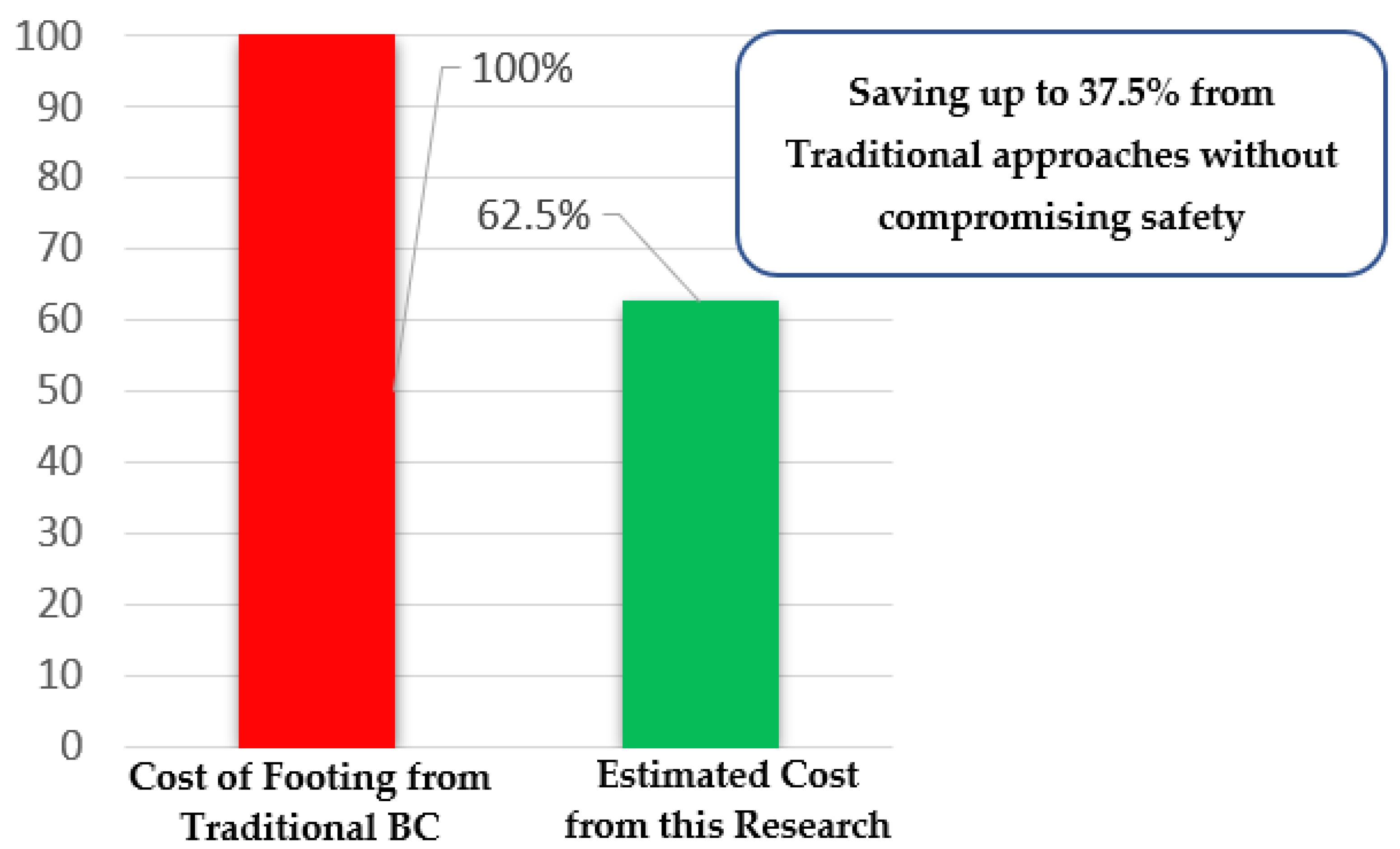
5.2. Comparison between Traditional and Optimized Foundation Design

This study compares the economic effect for the same footing using both traditional and optimized bearing capacity values obtained from this research while considering geotechnical and structural aspects of foundation design, along with cost at the same time. However, most of the discussion in literature is conceptual. [40] Wang et al. [12] proposed a spread footing framework, according to which 31% savings in cost can be made. However, the framework was based on a specific design example. Additionally, the model was framed for sandy soils only. Furthermore, the framework did not consider the structural design of the foundation. Rawat et al. [9] presented an analytical approach, according to which 8% savings in cost can be made using structural optimization of footing. Though, they did not consider the geotechnical design aspect. Figure 15 indicates that we can save up to 37.5% cost using an optimized design approach. This approach involves accurate and proper exploration of soil, proper investigation of intrinsic properties of soil, and using Vesic’s design charts with the lowest FoS.
Conventional design practices involve the use of excessive FoS. For example, FoS of 4 is usually used for design purposes. However, the proper use of FoS requires experience and state-of-the-art knowledge. Otherwise, excessive use of FoS values may lead to uneconomical conditions. Figure 16 presents an average saving of cost for three bearing capacity equations (Terzaghi, Meyerhof & Vesic) by changing FoS. This study concludes that by changing FoS from 4.0 to 3.5, approximately 14.3% of the cost can be saved from footing designed as compared to 4.0 FoS. Additionally, by changing FoS from 4.0 to 3.0 approximately 27.3% of the cost can be saved. It is worthwhile to note that the safety requirements are met, even at FoS 3.

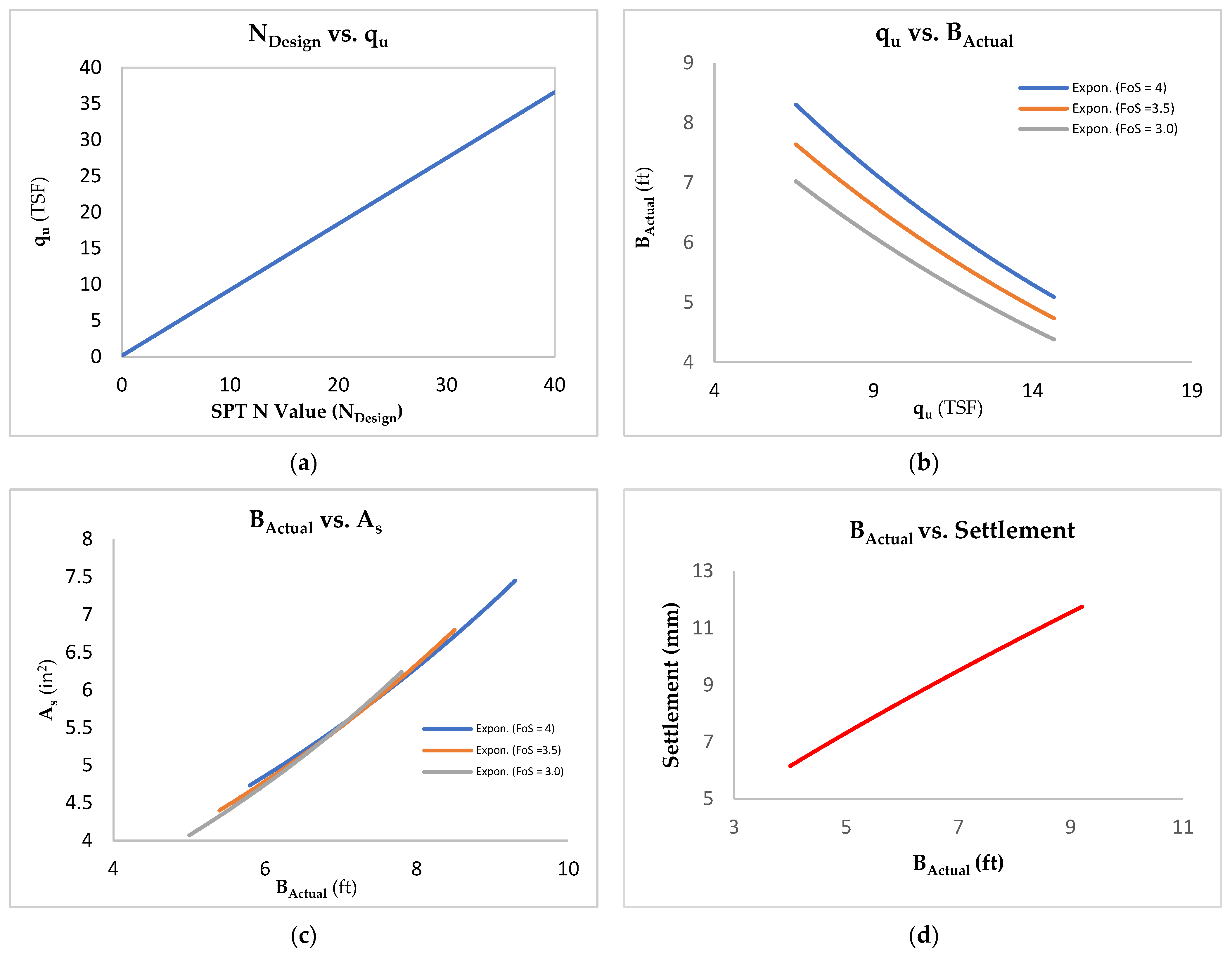
5.3. Proposed Framework

This framework considers the use of an SPT NDesign value along with the use of Vesic’s equation with a recommended lowest FoS. Then, obtained bearing capacity value will be utilized for the structural design of the footing. The SLS criteria should be thoroughly performed from PLAXIS-2D software, which relatively provides more accurate results.
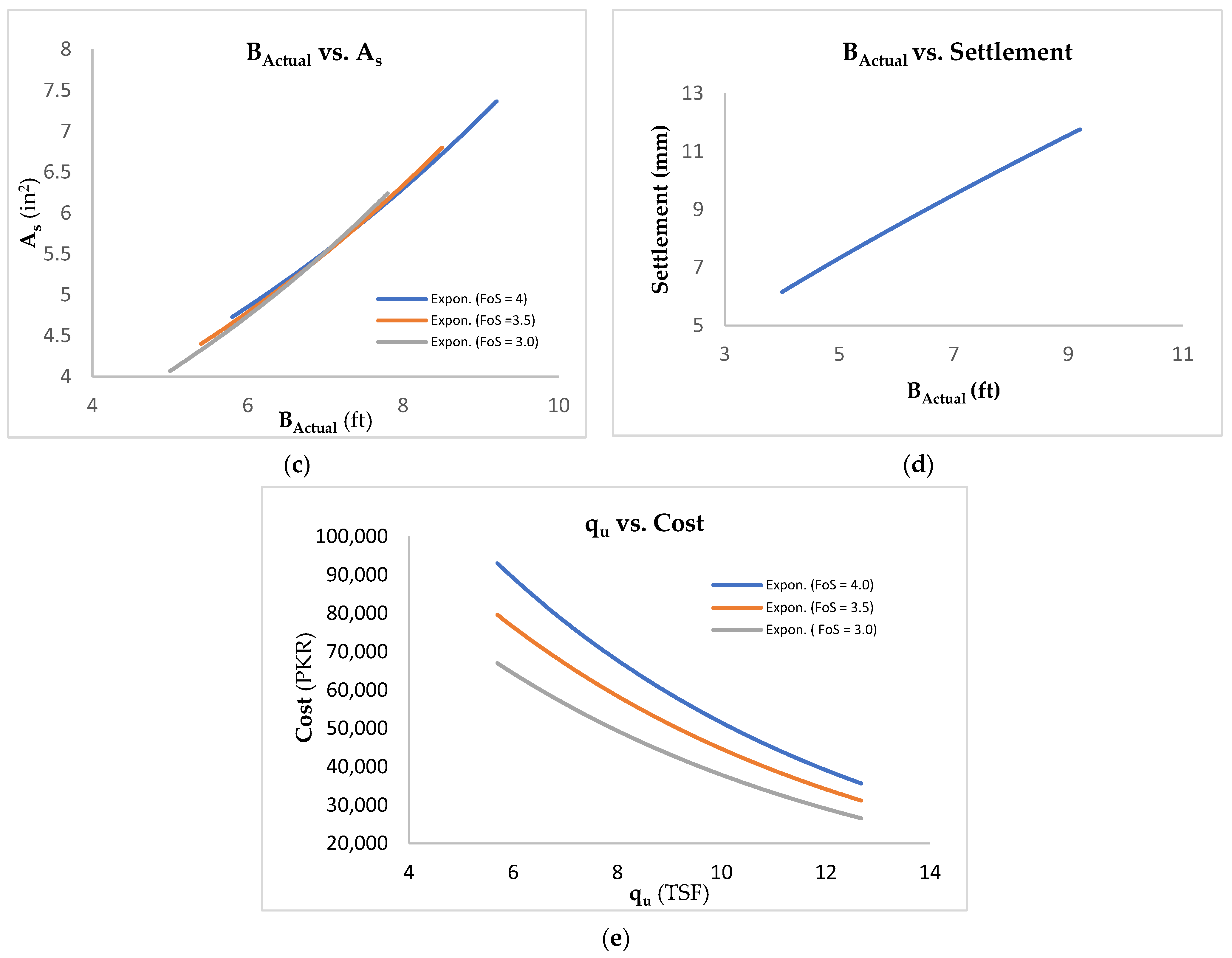
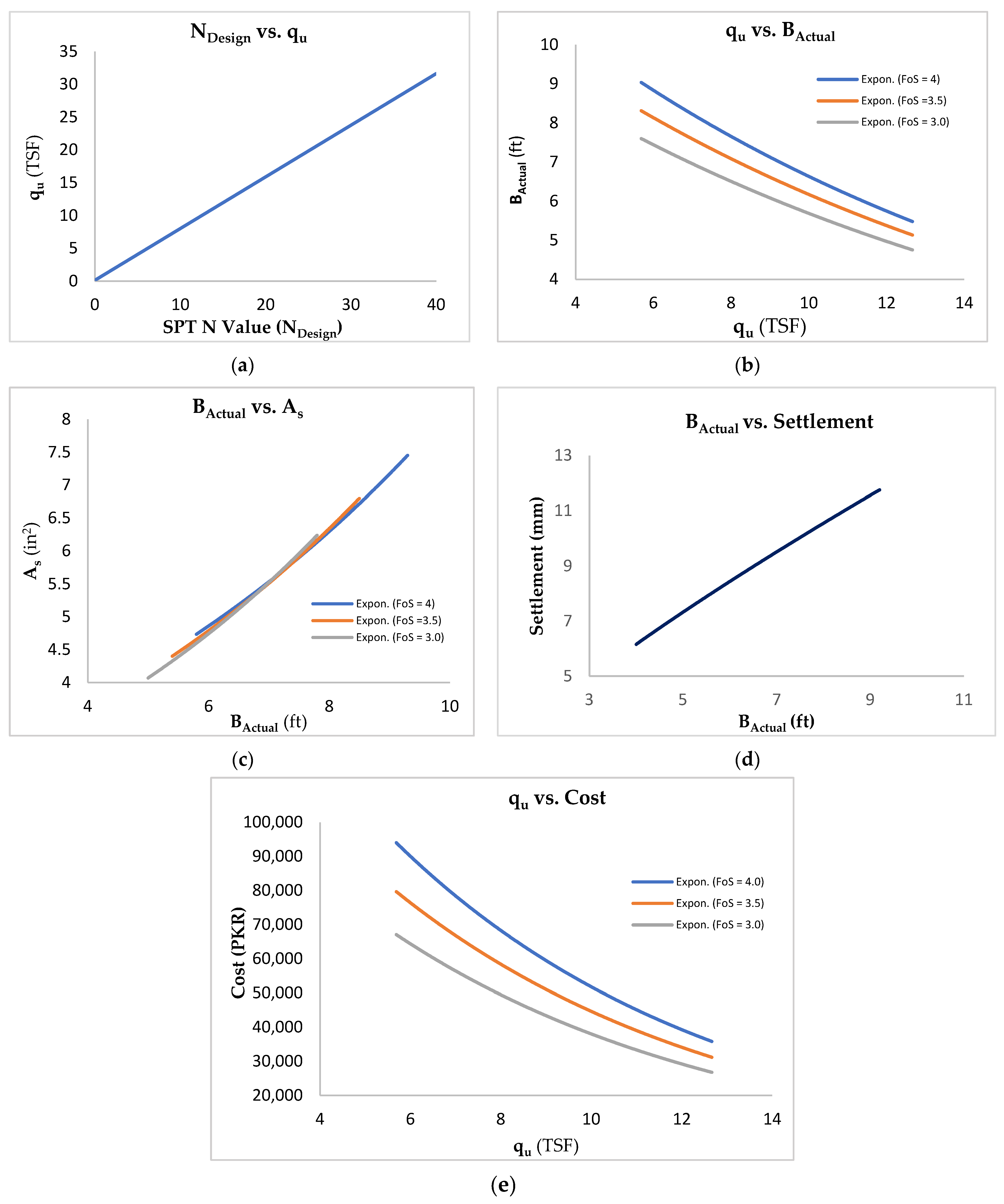
  • Step One: In the first step, NDesign will be selected using Equation (25). Then, the ultimate bearing capacity will be determined using Figure 12a based on NDesign value.
  • Step Two: In the second step, qu computed in the first step will be utilized to estimate the actual width of footing corresponding to desired FoS value using Figure 12b.
  • Step Three: The value of BActual computed in step two will be used to estimate the area of reinforcement from Figure 12c.
  • Step Four: The value of BActual will be used to assess the settlement of the footing in quantitative terms using Figure 12d.
  • Step Five: The value of qu will be used to assess the construction cost of footing in quantitative terms using Figure 12e.
Finally, the outcome of the proposed optimized model can be summarized such that it optimizes the foundation dimensions that would cause the possible least construction cost. This is achieved using a lower factor of safety whilst satisfying the safety requirements. Hence, the developed model gives the reduced footing dimensions and estimated quantitative cost that too using field SPT N data only with no further laboratory testing is required.

6. Conclusions

In the current study, an isolated foundation design approach was developed that considers ULS and SLS, along with the economy of the project. This approach is referred to as an optimization technique, in which the primary goal is to design a cost-effective foundation without compromising the safety requirements, i.e., ULS, and SLS. The following conclusions are drawn from the optimized foundation design in a specific cohesive soil.
  • This study presents an optimized model of foundation design comprising cost-based design charts which consider safety requirements, i.e., ULS, SLS, and economy at once. This developed optimized design approach provides a speedy method for foundation design for Silty Clay soils. The developed design charts can be used for an efficient economical design of shallow foundations considering safety requirements.
  • This study concludes that the conventional design practices inculcate the use of a higher FoS to compensate for the uncertainties, inaccuracies, and unavailability of enough soil investigation data. Contrary to that, this study provides the design charts to estimate the design of shallow foundations with the use of an appropriate FoS, even with the non-availability of enough data. The design charts are also useful in designing a cost-effective shallow foundation considering safety requirements.
  • Overconservative approaches may lead to an uneconomical situation. Therefore, it was observed that even the highest bearing capacity values, obtained from the utilized (Terzaghi, Meyerhof, Vesic) equations, can be recommended if they satisfy safety requirements. Thus, the highest bearing capacity computed can be recommended for the foundation design.
  • The results show that savings could be as much as 37.5% in comparison with the cost obtained from conventional foundation design. The optimized construction cost may change depending upon the subsurface soil conditions, design requirements, and groundwater conditions.
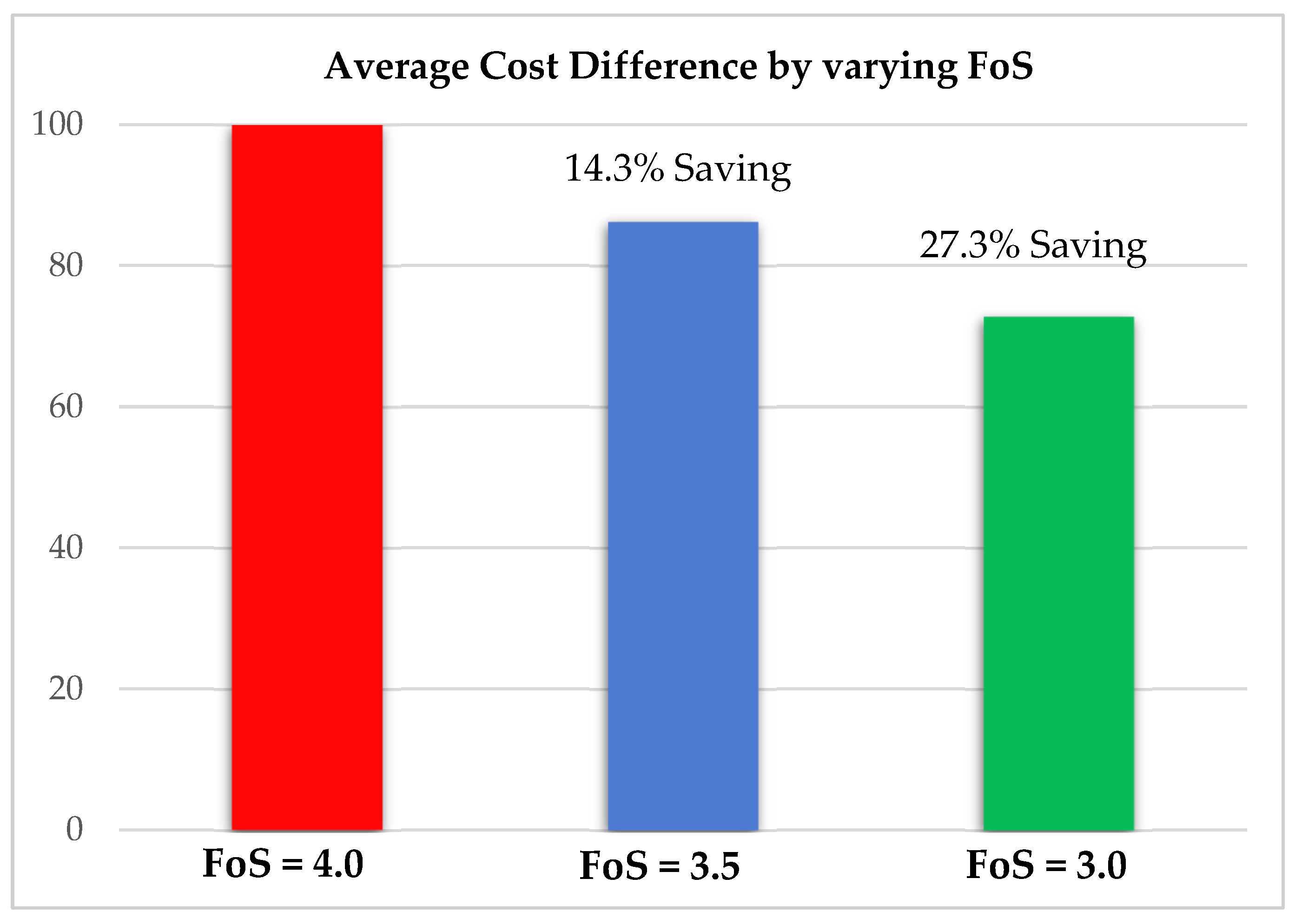
  • Statistical analysis shows there is a 0% probability of failure for low-rise buildings against the highest bearing capacity value and FoS equal to three or lesser can be used in general as the optimal value for design purposes to determine allowable bearing capacity. Since the average savings by changing FoS from 4.0 to 3.5 are 14.3% while changing FoS from 4.0 to 3.0 can be 27.3% can be achieved.
  • It is observed that even the most conservative approaches for the foundation yield more than 2 Tsf bearing capacity for the silty clayey soil.
  • Hence, future research may address other aspects of foundation design, such as seismic design parameters, variation of design loads, and validation of design charts through large-scale in-situ testing.

Author Contributions

Conceptualization, M.M.N., S.R.K., R.F. and M.A.U.R.T.; data curation, M.N.N. and J.K.; methodology, M.M.N., M.N.N. and R.F.; software, M.M.N., M.N.N. and S.R.K.; validation, M.M.N., M.N.N. and J.K.; formal analysis, S.R.K. and J.K.; investigation, M.N.N., S.R.K. and M.A.U.R.T.; resources, S.R.K.; writing—original draft preparation, M.M.N., S.R.K. and R.F.; writing—review and editing, S.R.K., R.F., M.M.N., A.W.M.N., D.F. and R.F.T.; visualization, M.N.N. and S.R.K.; supervision, S.R.K., R.F., M.A.U.R.T. and A.W.M.N.; project administration, S.R.K. and R.F. All authors have read and agreed to the published version of the manuscript.

Funding

The project presented in this article is supported by HEC NRPU Research Project No. 16414.

Institutional Review Board Statement

Not applicable.

Informed Consent Statement

Not applicable.

Data Availability Statement

Not applicable.

Conflicts of Interest

The authors declare no conflict of interest.

References

  1. Kuhlman, T.; Farrington, J. What is sustainability? Sustainability 2010, 2, 3436–3448. [Google Scholar] [CrossRef] [Green Version]
  2. Al-Taie, E. Analysis of Shallow Foundations in Three Different Regions in Iraq. Ph.D. Thesis, Luleå Tekniska Universitet, Luleå, Sweden, 2016. [Google Scholar]
  3. Wellington, A.M. The Economic Theory of the Location of Railways: An Analysis of the Conditions Controlling the Laying Out of Railways in Effect this Most Judicious Expenditure of Capital; John Wiley & Sons: Hoboken, NJ, USA, 1887. [Google Scholar]
  4. Coduto, D.P.; Kitch, W.A.; Yeung, M.R. Foundation Design: Principles and Practices; Prentice Hall: Hoboken, NJ, USA, 2001; Volume 2. [Google Scholar]
  5. Shahin, M.A.; Cheung, E.M. Probabilistic Analysis of Bearing Capacity of Strip Footings; Department of Civil Engineering, Curtin University: Perth, Australia, 2011; pp. 225–230. [Google Scholar]
  6. Azhim, A.; Prakoso, W.A. Construction cost optimization of shallow foundation for sand soil in Indonesia. MATEC Web Conf. 2019, 270, 05005. [Google Scholar] [CrossRef]
  7. Chaudhuri, P.; Maity, D. Cost optimization of rectangular RC footing using GA and UPSO. Soft Comput. 2020, 24, 709–721. [Google Scholar] [CrossRef]
  8. Juang, C.H.; Wang, L. Reliability-based robust geotechnical design of spread foundations using multi-objective genetic algorithm. Comput. Geotech. 2013, 48, 96–106. [Google Scholar] [CrossRef]
  9. Rawat, S.; Kant Mittal, R. Optimization of eccentrically loaded reinforced-concrete isolated footings. Pract. Period. Struct. Des. Constr. 2018, 23, 6018002. [Google Scholar] [CrossRef]
  10. Islam, M.S.; Rokonuzzaman, M. Optimized design of foundations: An application of genetic algorithms. Aust. J. Civ. Eng. 2018, 16, 46–52. [Google Scholar] [CrossRef]
  11. Wang, Y. Reliability-based economic design optimization of spread foundations. J. Geotech. Geoenviron. Eng. 2009, 135, 954–959. [Google Scholar] [CrossRef]
  12. Wang, Y.; Kulhawy, F.H. Economic design optimization of foundations. J. Geotech. Geoenviron. Eng. 2008, 134, 1097–1105. [Google Scholar] [CrossRef]
  13. Kashani, A.R.; Gandomi, M.; Camp, C.V.; Gandomi, A.H. Optimum design of shallow foundation using evolutionary algorithms. Soft Comput. 2020, 24, 6809–6833. [Google Scholar] [CrossRef]
  14. Khalid, M.H.; Alshameri, B.; Abid, U. Application of Kriging for development of SPT N value contour maps and USCS-based soil type qualitative contour maps for Islamabad, Pakistan. Environ. Earth Sci. 2021, 80, 413. [Google Scholar] [CrossRef]
  15. Luat, N.-V.; Nguyen, V.-Q.; Lee, S.; Woo, S.; Lee, K. An evolutionary hybrid optimization of MARS model in predicting settlement of shallow foundations on sandy soils. Geomech. Eng. 2020, 21, 583–598. [Google Scholar]
  16. Rabiei, M.; Choobbasti, A.J. Economic design optimization of piled raft foundations. Innov. Infrastruct. Solut. 2018, 3, 65. [Google Scholar] [CrossRef]
  17. Fathima Sana, V.K.; Nazeeh, K.M.; Dilip, D.M.; Sivakumar Babu, G.L. Reliability-Based Design Optimization of Shallow Foundation on Cohesionless Soil Based on Surrogate-Based Numerical Modeling. Int. J. Geomech. 2022, 22, 4021283. [Google Scholar] [CrossRef]
  18. Zhong, Z.; Zhang, S.; Zhao, M.; Hou, B.; Gong, W. Reliability-based robust geotechnical design of spread foundations considering multiple failure modes. Comput. Geotech. 2020, 119, 103292. [Google Scholar] [CrossRef]
  19. Moayedi, H.; Mosavi, A. A water cycle-based error minimization technique in predicting the bearing capacity of shallow foundation. Eng. Comput. 2021, 1–14. [Google Scholar] [CrossRef]
  20. Jaafar, K.; El-Halawani, L.I. Simulation-based multi-objective optimization model for machinery allocation in shallow foundation. Int. J. Constr. Manag. 2020, 20, 1–10. [Google Scholar] [CrossRef]
  21. Abdul-husain, H.A. Comparison of Theoretical Ultimate Bearing Capacity of Cohesionless Soils with Experimental And Field Data. J. Babylon Univ. Eng. Sci. 2016, 24, 596–603. [Google Scholar]
  22. ACI Committee 318. Building Code Requirements for Structural Concrete; American Concrete Institute: Indianapolis, IN, USA, 2014; ISBN 9780870317446. [Google Scholar]
  23. Pereira, C.; Caldeira, L. Shallow Foundation Design through Probabilistic and Deterministic Methods. In Proceedings of the 3rd International Symposium on Geotechnical Safety and Risk (ISGSR 2011), Munich, Germany, 2–3 June 2011. [Google Scholar]
  24. Terzaghi, K. Theoretical Soil Mechanics; John Wiley & Sons: Hoboken, NJ, USA, 1943. [Google Scholar]
  25. Meyerhof, G.G. The ultimate bearing capacity of foudations. Geotechnique 1951, 2, 301–332. [Google Scholar] [CrossRef]
  26. Vesic, A.S. Bearing Capacity of Shallow Foundations. In Foundation Engineering Handbook; Winterkorn, F.S., Fand, H.Y., Eds.; Springer: Boston, MA, USA, 1975. [Google Scholar]
  27. Hettiarachchi, H.; Brown, T. Use of SPT blow counts to estimate shear strength properties of soils: Energy balance approach. J. Geotech. Geoenviron. Eng. 2009, 135, 830–834. [Google Scholar] [CrossRef]
  28. Rahman, M. Foundation Design using Standard Penetration Test (SPT) N-value. Researchgate 2019, 5, 1–39. [Google Scholar] [CrossRef]
  29. Das, B.M. Principles of Foundation Engineering, 8th ed.; Cengage Learning: Boston, MA, USA, 2015; ISBN 1305537890. [Google Scholar]
  30. Budhu, M. Soil Mechanics and Foundations; John Wiley & Sons: Hoboken, NJ, USA, 2010; ISBN 0470556846. [Google Scholar]
  31. Bowles, J.E. Foundation Engineering; McGraw Hills: Singapore, 1997. [Google Scholar]
  32. Sivakumar Babu, G.L.; Srivastava, A.; Murthy, D.S.N. Reliability analysis of the bearing capacity of a shallow foundation resting on cohesive soil. Can. Geotech. J. 2006, 43, 217–223. [Google Scholar] [CrossRef]
  33. Foye, K.C.; Salgado, R.; Scott, B. Resistance factors for use in shallow foundation LRFD. J. Geotech. Geoenviron. Eng. 2006, 132, 1208–1218. [Google Scholar] [CrossRef]
  34. Cheng, L. Soils and Foundations; Food and Agriculture Organization of the United Nations: Rome, Italy, 1992. [Google Scholar]
  35. Guleria, A. Structural analysis of a multi-storeyed building using ETABS for different plan configurations. Int. J. Eng. Res. Technol. 2014, 3, 1481–1485. [Google Scholar]
  36. Mirmohammad, S.S.J.; Babaei, A.L.I.R. Structural optimization of B70 railway prestressed concrete sleepers. Iran. J. Sci. Technol. Trans. B Eng. 2006, 30, 461–473. [Google Scholar]
  37. Teli, S.; Kundhani, P.; Choksi, V.; Sinha, P.; Iyer, K.K.R. Influence of Loading and Soil Modeling Approach on Soil-Shallow Foundation Interaction. In Lecture Notes in Civil Engineering, Proceedings of the Indian Geotechnical Conference 2019; Springer: Singapore, 2021; pp. 505–514. [Google Scholar]
  38. Sherazi, S.M.A.; Hassan, S.; Sherazi, A. (Eds.) National Highway Authority Composite Schedule of Rates (Punjab); SAMPAK International (Pvt.) Ltd.: Punjab, Pakistan, 2014. [Google Scholar]
  39. Bledsoe, J.D. From Concept to Bid: Successful Estimating Methods; RS Means Company: Rockland, MA, USA, 1992; ISBN 0876292163. [Google Scholar]
  40. Das, B.M. Principles of Foundation Engineering, 7th ed.; Cengage Learning: Boston, MA, USA, 2002; ISBN 0534030521. [Google Scholar]
Figure 1. Optimization framework of the study.
Sustainability 14 05699 g001
Figure 2. Steps of a generalized design procedure in CSI ETABS software.
Sustainability 14 05699 g002
Figure 3. Design of building in CSI ETABS: (a) Ground floor plan; (b) 3-Dimensional view.
Sustainability 14 05699 g003
Figure 4. Steps of a generalized design procedure in CSI SAFE software.
Sustainability 14 05699 g004
Figure 5. Square isolated building design in CSI SAFE software.
Sustainability 14 05699 g005
Figure 6. Stepwise procedure for PLAXIS 2D modeling.
Sustainability 14 05699 g006
Figure 7. An illustration of a construction site simulation model using PLAXIS 2D software.
Sustainability 14 05699 g007
Figure 8. Analyzed 3D model of the building for critical column design using CSI ETABS software.
Sustainability 14 05699 g008
Figure 9. An analyzed model of the footing in CSI SAFE software.
Sustainability 14 05699 g009
Figure 10. Results of settlement analysis of a footing through PLAXIS-2D software.
Sustainability 14 05699 g010
Figure 11. Design charts based on Terzaghi’s bearing capacity equation (a) relation between the SPT NDesign value and ultimate bearing capacity; (b) relation between ultimate bearing capacity and the actual width of the foundation; (c) relation between the actual width of footing and the required area of steel; (d) relation between the actual width and the amount of settlement; and (e) estimated cost against the different ultimate bearing capacity values.
Sustainability 14 05699 g011aSustainability 14 05699 g011b
Figure 12. Design charts based on Meyerhof’s bearing capacity equation (a) relation between the SPT NDesign value and ultimate bearing capacity; (b) relation between ultimate bearing capacity and the actual width of the foundation; (c) relation between the actual width of footing and the required area of steel; (d) relation between the actual width and the amount of settlement; and (e) estimated cost against the different ultimate bearing capacity values.
Sustainability 14 05699 g012
Figure 13. Design charts based on Vesic’s bearing capacity equation (a) relation between the SPT NDesign value and ultimate bearing capacity; (b) relation between ultimate bearing capacity and the actual width of the foundation; (c) relation between the actual width of footing and the required area of steel; (d) relation between the actual width and the amount of settlement; and (e) estimated cost against the different ultimate bearing capacity values.
Sustainability 14 05699 g013aSustainability 14 05699 g013b
Figure 14. Design model provides the optimization of different materials for the footing as compared to traditional design, and these include (a) Concrete; (b) Reinforcement; (c) Formwork; and (d) Excavation.
Sustainability 14 05699 g014aSustainability 14 05699 g014b
Figure 15. Average economical difference between a traditional & optimized footing cost.
Sustainability 14 05699 g015
Figure 16. Average cost saving for a footing by varying FoS for design.
Sustainability 14 05699 g016
Table 1. Properties of material used for designing building in CSI ETABS.
Material Strength of MaterialUsage
Concrete 3000 PsiFor beams and slabs
Concrete 4000 PsiFor columns and footings
RebarGrade 60Longitudinal (main) reinforcement
RebarGrade 40Confinement bars (ties)
Table 2. Properties of Sections used for designing building in CSI ETABS.
SectionSizeSectionSizeSectionSize
Columns15″ × 15″Beams 18″ × 15″Slab6″ Thick
Table 3. Summary of unit prices for a shallow foundation [38].
MaterialsLaborMaterialUnit
ConcretePKR 4714PKR 5600Cubic Yard
ReinforcementPKR 12PKR 112Kilogram
FormworkPKR 18PKR 14Sq. ft/contact area
ExcavationPKR 216PKR 0Cubic Yard
Publisher’s Note: MDPI stays neutral with regard to jurisdictional claims in published maps and institutional affiliations.

