Article

Calculation and Analysis of Unbalanced Magnetic Pull of Rotor under Motor Air Gap Eccentricity Fault

1
School of Mathematics and Physics, Shanghai University of Electric Power, Shanghai 200090, China
2
School of Energy and Mechanical Engineering, Shanghai University of Electric Power, Shanghai 200090, China
*
Author to whom correspondence should be addressed.
Sustainability 2023, 15(11), 8537; https://doi.org/10.3390/su15118537
Submission received: 12 March 2023 / Revised: 3 May 2023 / Accepted: 10 May 2023 / Published: 24 May 2023
(This article belongs to the Special Issue Sustainable Science and Technologies of Intelligent Manufacturing)

Abstract

:
Due to various factors such as manufacturing, assembly and operation, the motor air gap will be uneven in the circumferential direction, resulting in the air gap eccentricity having a longer air gap on one side and a shorter air gap on the other side, which affects the normal operation and service life of the motor. This paper analyzed and compared the applicability of linear and nonlinear calculation methods of unbalanced magnetic pull. Based on the method of finite element analysis, the unbalanced magnetic pull of motor rotor under static eccentricity, dynamic eccentricity and compound eccentricity faults were calculated, and the influence of eccentricity on unbalanced magnetic pull was compared, respectively. The results showed that when the motor has static eccentricity, the main components of unbalanced magnetic pull on the rotor are zero frequency and twice the electrical frequency. When the motor has dynamic eccentricity, the unbalanced magnetic tension component of the rotor is mainly frequency conversion. When the motor has two faults at the same time, the unbalanced magnetic pull has zero frequency, rotating frequency and double electric frequency components at the same time. With the increase in the relative eccentricity, the frequency components of the unbalanced magnetic pull under the three faults increase. An air gap eccentricity fault widely exists in motor equipment. When the unbalanced magnetic pull increases to a certain extent, the rotor will be pulled towards the stator, causing the occurrence of rub-impact phenomenon, and seriously threatening the safe operation of the system. In this paper, the numerical analysis method and finite meta-computing method were used for the first time to analyze and compare the unbalanced magnetic pull on the rotor of permanent magnet synchronous motor under three kinds of air gap eccentricity faults. The results showed that the characteristic frequency amplitude of the unbalanced magnetic pull calculated by the two methods is relatively close. Therefore, it is of great significance to carry out calculation and analysis of the unbalanced magnetic pull force under the air gap eccentric fault of the motor.

1. Introduction

Motors are widely used in industry and life, and the rotor is the most important part of the motor. The operation quality of a rotor directly determines the operation performance of a motor.
The motor air gap refers to the gap between the stator and rotor. Under ideal conditions, the air gap between the stator and rotor is uniform and symmetrical. At this time, the resultant force of radial magnetic pull along the rotor circumference is zero [1].
However, the motor air gap will be uneven in the circumferential direction due to various reasons of manufacturing, assembly and operation, resulting in a longer air gap on one side and a shorter air gap on the other side, which is called air gap eccentricity.
For example, uneven rotor mass distribution and defects on the stator surface cause air gap eccentricity. At this time, the resultant force of rotor radial magnetic pull is no longer zero, and that of the magnetic pull is called the unbalanced magnetic pull [2].
In order to simplify this, the unbalanced magnetic pull is simplified into the English abbreviation UMP. According to the difference of air gap eccentricity, it can be divided into static eccentricity, dynamic eccentricity and static dynamic mixed eccentricity [3].
The static eccentricity of air gap refers to the circumferential position of the minimum radial air gap between the rotor and stator, remaining unchanged and unchanging with the rotation of the rotor, which is mainly caused by the misalignment between the stator center and the initial center of the journal.
Air gap dynamic eccentricity refers to the change of the minimum radial air gap position between the rotor and stator with the rotation of the rotor, which is mainly caused by the misalignment of the geometric center of the rotor and the center of the deformed journal. The mixed static and dynamic eccentricity of the air gap refers to the coexistence of the static and dynamic eccentricity of the air gap, as shown in Figure 1.
In the figure, O is the center of the stator, O1 is the center of the journal after deformation, O2 is the geometric center of the rotor, S is the initial center of the journal and G is the center of gravity of the rotor. α is the mechanical angle of the stator, γ is the angle of rotation of the rotor center. ω is the electrical angular velocity, which is the rotor angular velocity multiplied by the number of motor poles. OS is the static eccentricity of the rotor, O1O2 is the dynamic eccentricity of the rotor, and when both exist, it is the mixed eccentricity.
A small amount of air gap eccentricity will not have too much impact on the normal operation of the motor. However, when the eccentricity reaches 10% of the radial air gap value, it is considered that the fault standard [4] is reached. Then, human intervention is required to maintain the vibration stability of the shafting, and protect the bearing and winding insulation from damage.
In general, the dynamic eccentricity is relatively small, and it is difficult to reach the 10% fault threshold [5]. However, static eccentricity and mixed eccentricity containing static eccentricity components can easily reach this threshold due to bearing damage, offset or core deformation. Therefore, it is very important to study the influence of unbalanced magnetic tension on the vibration of rotor system, whether for the design of the unit or the state maintenance.
Scholars in relevant fields have carried out a lot of research on motor UMP. Zhou ST et al. [6] calculated the dynamic response of the traction motor rotor of a type of EMU under the action of unbalanced magnetic pull and mechanical unbalanced force, and discussed in detail the influence of initial static eccentricity, mass eccentricity, radial stiffness and speed on the system vibration characteristics.
Di and Chong et al. [7] analyzed the UMPs of a 2 MW, 12,000 r/min IM in the static eccentricity, dynamic eccentricity and mixed eccentricity conditions.
Zhou S.T. et al. [8] studied the influence of initial static eccentricity and gravity load on traction motor rotor axis locus and displacement spectrum. Wu Y.C. et al. [9] simulated rotor dynamic and static eccentricity faults and rotor winding interturn short circuit faults, respectively, calculated unbalanced magnetic pull under each fault condition, and analyzed the influence of rotor eccentricity, direction and rotor winding interturn short circuit degree on the magnitude and direction of unbalanced magnetic pull. Chuan Hawwooi et al. [10] proposed a UMP reduction method using active control methods, utilizing the nonlinear relationship between UMP and rotor slip. Meanwhile, an analytical model to find the slip with the lowest UMP is presented, by which the UMP can be reduced by controlling the excitation voltage. In addition, the problem of UMP surge when controlling the slip during the transient state is discussed. Zhang L.K. et al. [11] solved the unbalanced magnetic tension by using the semi analytical and semi numerical harmonic balance time-frequency domain conversion method, and compared the results with those calculated by Runge Kutta method. Kumar Gaurav et al. [12] established a finite element model of a bridge induction motor and studied the effects of different eccentricity conditions on UMP and bridge current. Feng W. et al. [13] simulated the unbalanced magnetic tension of the radial dynamic eccentric and inclined eccentric rotors by using the semi analytical method, and simulated and analyzed the vibration response of the rotor in the time and frequency domains. Guo S.J. et al. [14] used experimental and numerical methods to study the coupling effect of unbalanced magnetic pull and ball bearing on nonlinear vibration of three-phase asynchronous motor. Li X.W. et al. [15] described the magnetic field distribution by using the infiltration network method, and obtained the unbalanced magnetic pull by using the virtual work method. They studied the physical characteristics of the unbalanced magnetic pull and its frequency components in the angular domain. Hao J. et al. [16] established a generalized time-varying dynamic model of the motor rotor to evaluate the impact of unbalanced magnetic tension on the rotor system. Liu F. et al. [17] studied the influence of mass eccentricity, static radial eccentricity and angular eccentricity in the rotor of permanent magnet synchronous motor on the combined eccentric rotor system. Most of the existing researches focus on the numerical solution of UMP, but the numerical solution usually omits the high-order part of the air gap permeance, which is difficult to restore the working condition of the real motor, and there is less comprehensive research on the three types of air gap eccentric faults. This paper will calculate the UMP of the rotor under three kinds of air gap eccentricity faults, namely, the air gap static eccentricity fault, the air gap dynamic eccentricity fault and the air gap dynamic and static mixed eccentricity fault, through the finite element software for the permanent magnet synchronous motor, to provide theoretical support for the reliability of the motor equipment operation. The characteristic frequency of unbalanced magnetic pull obtained in this article can be used to determine the type of air gap eccentricity fault in permanent magnet synchronous motors, and can better detect the operating status of the motor rotor system.

2. Calculation Method of UMP

The calculation methods of UMP mainly include the linear calculation method and nonlinear calculation method.

2.1. Calculation Method of Linear Empirical Formula

The calculation method of the linear empirical formula has high accuracy when the air gap eccentricity is small. Chen Shikun [18] considered the effects of different motor types, magnetic field distribution, magnetic circuit saturation, slotting and other structures, and considering that the amplitude of UMP is proportional to the rotor eccentricity, gave the following formula:
F = β π D L ( B 5000 ) 2 e δ
where L is the rotor length, D is the rotor radius, β is the coefficient related to the damping winding of the magnetic field distribution, generally taken as 0.2–0.5; δ is the rotor stator clearance, e is the eccentricity and B is the magnetic flux density.
Lai W.H. [19] ignored the end effect of the motor, thought that UMP was proportional to the difference between the magnetic density at the minimum air gap and the maximum air gap, and gave Equation (2):
F = π D L 4 μ 0 ( B min 2 B max 2 )
among them, μ 0 is the vacuum permeability, B min is the average magnetic density of the magnetic pole at the minimum air gap, B max is the average magnetic density of the magnetic pole at the maximum air gap.

2.2. Nonlinear Calculation Method

When the air gap eccentricity is large, the UMP calculated by the linear empirical formula has a large error. At this time, it is necessary to accurately calculate the air gap permeance. By expanding the air gap permeance series and omitting the higher-order components, a more accurate series expression of air gap permeance can be obtained.
The air gap length of stator at any angle and time is:
δ ( α , t ) = δ 0 [ 1 ε cos ( α γ ) ]
The air gap permeance is expanded by the Fourier series to obtain Equation (3). It can be seen from Formula (3) that the smaller the air gap length is, the greater the amplitude of air gap permeability is.
Λ ( α , t ) = μ 0 δ ( α , t ) = μ 0 δ 0 [ 1 ε cos ( α γ ) ] = μ 0 δ 0 n = 0 ε n · cos n ( α γ ) = n = 0 Λ n · cos ( α γ )
The nonlinear calculation methods mainly include the Maxwell stress integration method and energy method.

2.2.1. Energy Method

First, the air gap magnetic field energy was obtained, and then the x and y directions were calculated, respectively, to obtain the UMP in the x and y directions.
The expression of air gap magnetic field energy is as follows [20]:
W = R 2 0 L 0 2 π Λ ( α , t , z ) F 1 2 ( α , t ) d z d α
where F 1 is the composite fundamental magnetomotive force of the stator and rotor and W is the air gap magnetic energy.
F 1 = F s m cos ( α ω t ) + F r m cos ( α ω t π 2 ψ p ϕ )
where F s m is the amplitude of the stator fundamental magnetomotive force, F r m is the amplitude of the rotor fundamental excitation magnetomotive force, ψ is the angle of internal power rate, ϕ is the torsional vibration angle of the motor, and p is the number of magnetic poles of the motor.
F x = W x F y = W y
where F x is the component force of UMP in x direction, F y is the component of UMP in y direction.

2.2.2. Maxwell Stress Integration Method

Firstly, the electromagnetic force per unit area of the rotor was calculated, and then the UMP of the rotor was obtained by integrating along the rotor circumference.
F x = R L 0 2 π σ ( α , t ) cos α d α F y = R L 0 2 π σ ( α , t ) sin α d α
where σ(α,t) is the electromagnetic force per unit area of the rotor which can be obtained from Formula (9):
σ ( α , t ) = B 2 ( α , t ) 2 μ 0
Air gap magnetic density B is obtained from Equation (10):
B ( α , t ) = Λ ( α , t ) F 1
By bringing Equations (9) and (10) into Equation (8), the UMP in x and y directions under different motor pole pairs can be calculated, as shown in Equation (11) [21]:
F x = f 1 cos γ + f 2 cos ( 2 ω t γ ) + f 3 cos ( 2 ω t 3 γ ) , P = 1 f 1 cos γ + f 3 cos ( 2 ω t 3 γ ) + f 4 cos ( 2 ω t 5 γ ) , P = 2 f 1 cos γ + f 4 cos ( 2 ω t 5 γ ) , P = 3 f 1 cos γ , P > 3 F y = f 1 sin γ + f 2 sin ( 2 ω t γ ) + f 3 sin ( 2 ω t 3 γ ) , P = 1 f 1 sin γ + f 3 sin ( 2 ω t 3 γ ) + f 4 sin ( 2 ω t 5 γ ) , P = 2 f 1 sin γ + f 4 sin ( 2 ω t 5 γ ) , P = 3 f 1 sin γ , P > 3
where:
f 1 = R L π 4 μ 0 F j 2 ( 2 Λ 0 Λ 1 + Λ 1 Λ 2 + Λ 2 Λ 3 ) f 2 = R L π 4 μ 0 F j 2 ( Λ 0 Λ 1 + 1 2 Λ 1 Λ 2 + 1 2 Λ 2 Λ 3 ) f 3 = R L π 4 μ 0 F j 2 ( Λ 0 Λ 3 + 1 2 Λ 1 Λ 2 ) f 4 = R L π 8 μ 0 F j 2 Λ 2 Λ 3
Λ n = μ 0 δ 0 1 1 ε 2 ( n = 0 ) 2 μ 0 δ 0 1 1 ε 2 1 1 ε 2 ε n ( n > 0 )
where F j is the amplitude of rotor fundamental magnetomotive force, ε is the relative eccentricity of the rotor, which is equal to e / δ 0 . ω represents electrical angular velocity, γ is the direction angle of the rotor motion center, which is equal to r 0 cos γ 0 + x 2 + r 0 sin γ 0 + y 2 . r 0 is the static eccentricity of the rotor, x and y are the radial vibration displacements of the rotor, when r 0 = 0, the system only has dynamic eccentricity. When r is not 0, the system has mixed eccentricity. It can be seen from Equations (11)–(13) that when there is only static eccentricity, the frequency domain components of rotor vibration are mainly zero frequency and double electric frequency. When there is only dynamic eccentricity, the frequency domain component of rotor vibration is dominated by the frequency conversion component. When both eccentricities exist, the frequency components of rotor vibration are mainly zero frequency, rotational frequency and double electrical frequency.

3. Finite Element Simulation

3.1. Numerical Calculation

In this paper, single-disk double-support rotor-bearing was taken as the research object and the influence of gyro moment was ignored. Its dynamic model is shown in Figure 2. Assuming that the shaft section of the rotor has no mass, the disk is at the center of the shaft, the concentrated mass of the central disk is m, the stiffness coefficient of the rotor-bearing system is k, the damping coefficient of the bearings at both ends is c, the damping coefficient of the central disk is c, O is the centroid of the rotor, x and y are the radial displacements of the disk in the X and Y directions and the unbalanced magnetic force acts on the central disk.
The dynamic equation of rotor-bearing system is as follows:
m x ¨ + c x ˙ + k x = m e ω 2 cos ( ω t ) F x m y ¨ + c y ˙ + k y = m e ω 2 sin ( ω t ) F y m g
Adopting Newmark-β, the nonlinear differential equations were solved by numerical integration method to obtain the dynamic response of the rotor. Iteration step length Δt = 1 × 10⁻⁵ s, initial displacement of rotor was x = 1 × 10⁻⁶ m, y = 1 × 10⁻⁶ m, the initial speed was 0 and the rotational speed was 3000 r/min. The rounding error caused by the initial value was eliminated, and the UMP under the fault of rotor air gap static eccentricity, air gap dynamic eccentricity and air gap dynamic and static mixed eccentricity were calculated, respectively. Relevant parameters are shown in Table 1.
Figure 3 shows the time domain waveform and spectrum of UMP on the rotor when the static eccentricity was 0.2 mm. From Figure 3a,b it can be seen that the UMP in the x direction was mainly composed of zero frequency and double electric frequency components. It can be seen from Figure 3c,d that the zero frequency component of the UMP in the y direction disappears, and the frequency component was mainly twice the electrical frequency.
(1)
UMP of rotor under static eccentricity of air gap
Figure 3. (a) time domain diagram of UMP in x direction (b) spectrum diagram of UMP in x direction (c) time domain diagram of UMP in y direction (d) spectrum diagram of UMP in x direction of the static eccentricity = 0.2 mm.
Sustainability 15 08537 g003
Figure 4 shows the time domain waveform and spectrum of UMP on the rotor when the dynamic eccentricity is 0.2 mm. It can be seen from Figure 4a–d that the frequency components of UMP in the x and y directions were mainly the frequency components.
(2)
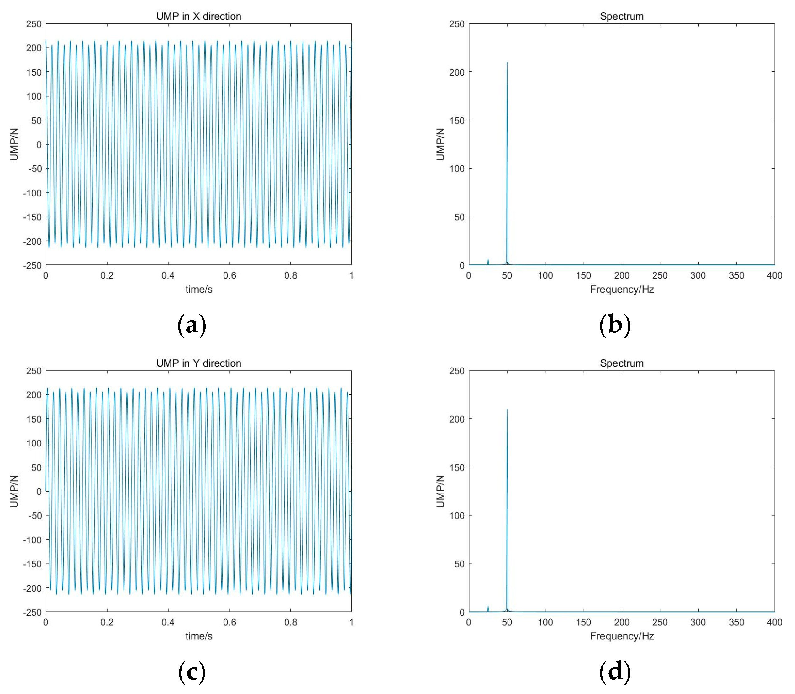
UMP of rotor under dynamic eccentricity of air gap
Figure 4. (a) time domain diagram of UMP in x direction (b) spectrum diagram of UMP in x direction (c) time domain diagram of UMP in y direction (d) spectrum diagram of UMP in x direction of the dynamic eccentricity = 0.2 mm.
Sustainability 15 08537 g004
Figure 5 shows the time domain waveform and spectrum of the unbalanced magnetic pull on the rotor when the static eccentricity was 0.2 mm, that is, the static eccentricity and the dynamic eccentricity existed at the same time and were 0.2 mm. From Figure 5a,b, it can be seen that the UMP in the x direction was mainly composed of zero frequency, rotating frequency and double electric frequency components. It can be seen from Figure 5c,d that the zero frequency component of the UMP in the y direction disappears, and the frequency component was mainly rotational frequency and double electrical frequency.
(3)
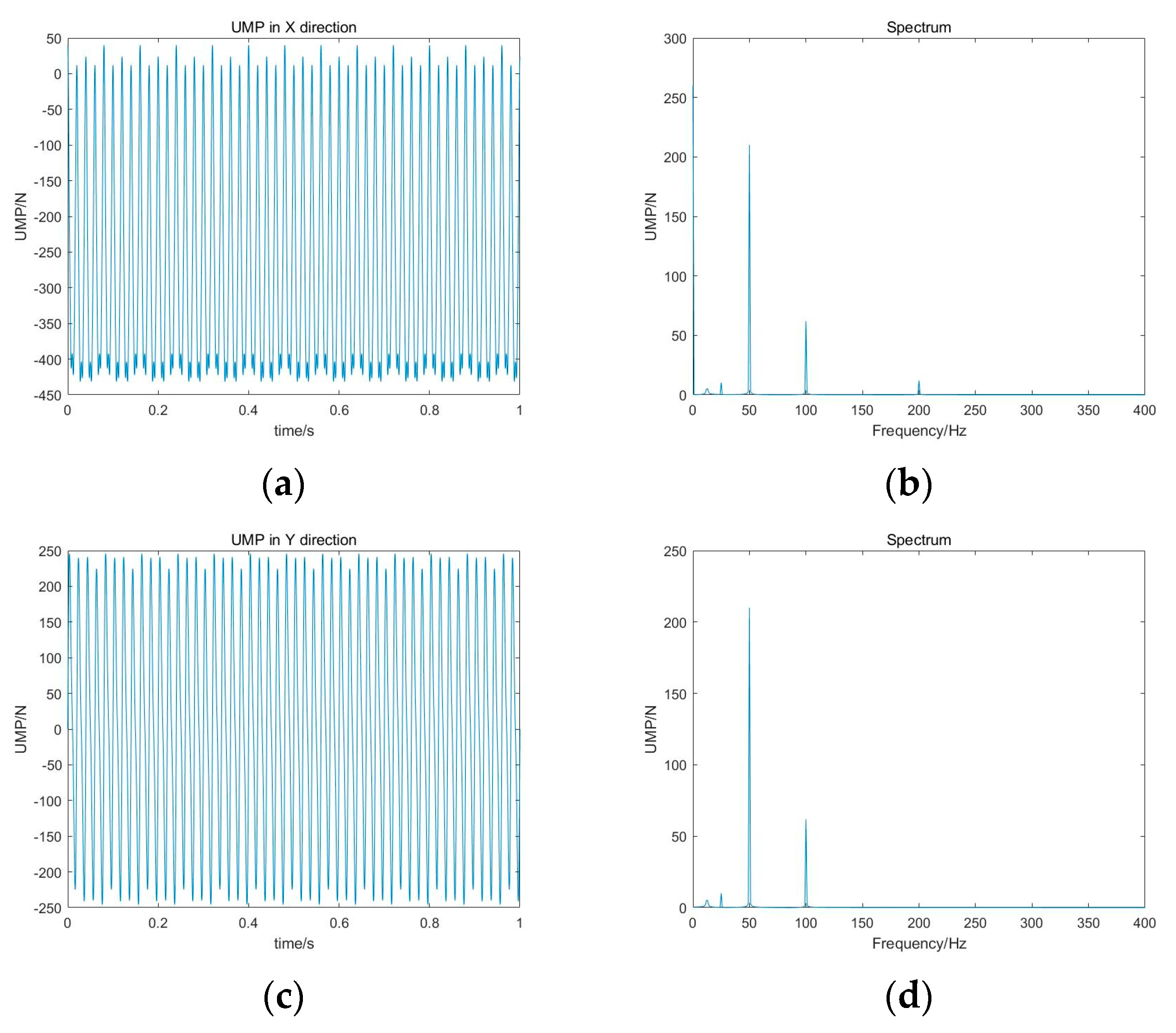
UMP of rotor under mixed with static and dynamic eccentricity of air gap
Figure 5. (a) time domain diagram of UMP in x direction (b) spectrum diagram of UMP in x direction (c) time domain diagram of UMP in y direction (d) spectrum diagram of UMP in x direction of the dynamic eccentricity = 0.2 mm.
Sustainability 15 08537 g005

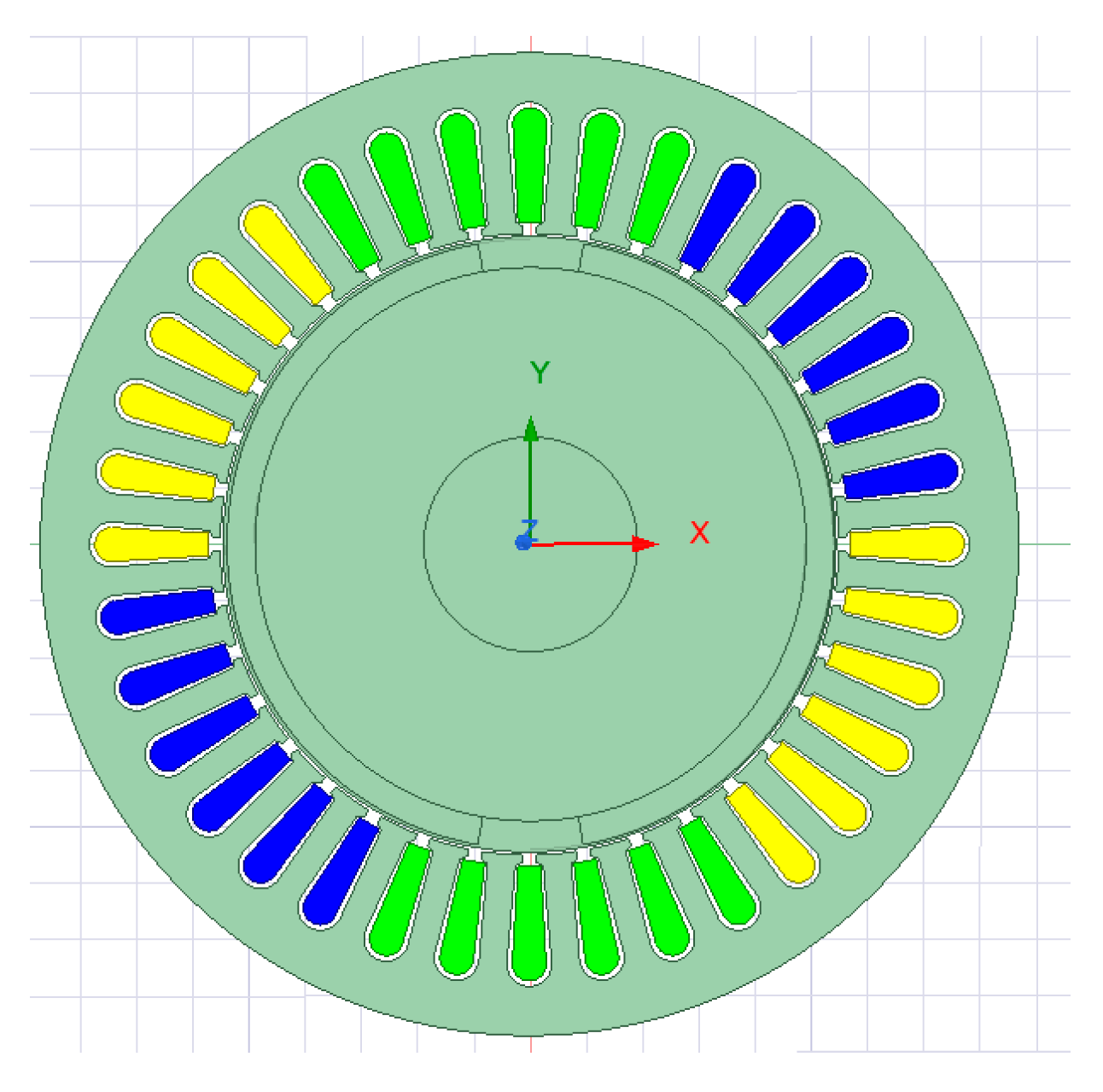
3.2. Finite Element Simulation Based on Maxwell

The UMP calculation based on the finite element model is closer to the UMP received by the actual motor. In this paper, the motor air gap eccentric fault was simulated through the Ansys Maxwell software. Eccentricity in this paper was carried out along the x direction. The speed of the motor was 3000 r/min and the permanent magnet synchronous motor with single pair of magnetic poles was used, as shown in Figure 6. The simulation of static eccentricity was realized by keeping the stator center unchanged, and moving the motor rotation center and the rotor center by the same distance to x at the same time. The simulation of dynamic eccentricity kept the stator center and motor rotation center unchanged and the rotor center moved a certain distance to the x-axis. The mixed eccentricity is realized by keeping the stator center unchanged and moving the rotor center and motor rotation center to the x-axis by the same distance, respectively.
When the air gap is uniform, the combined external force of the magnetic pull on the rotor along the circumference is 0. As can be seen from Figure 7, the amplitude of UMP is close to 0.
(1)
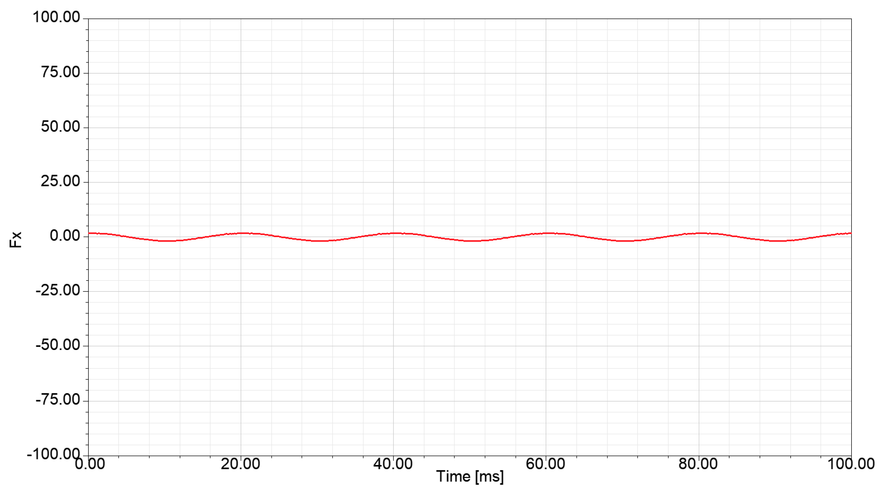
UMP of rotor under normal conditions
Figure 7. UMP in normal state.
Sustainability 15 08537 g007
The black, red and blue curves in Figure 8 are the time domain waveform when the static eccentricity is 0.05 mm, 0.1 mm and 0.2 mm, respectively. It can be seen from Figure 4a that the amplitude of UMP in the x direction was below 0, which is due to the negative stiffness effect of UMP on the rotor system. Since the eccentric angle of the rotor in the experiment is along the x direction, the γ angle is 0° in Formula (7) and there is a zero frequency component in the x direction that does not change with time, and its amplitude is f 1 .
(2)
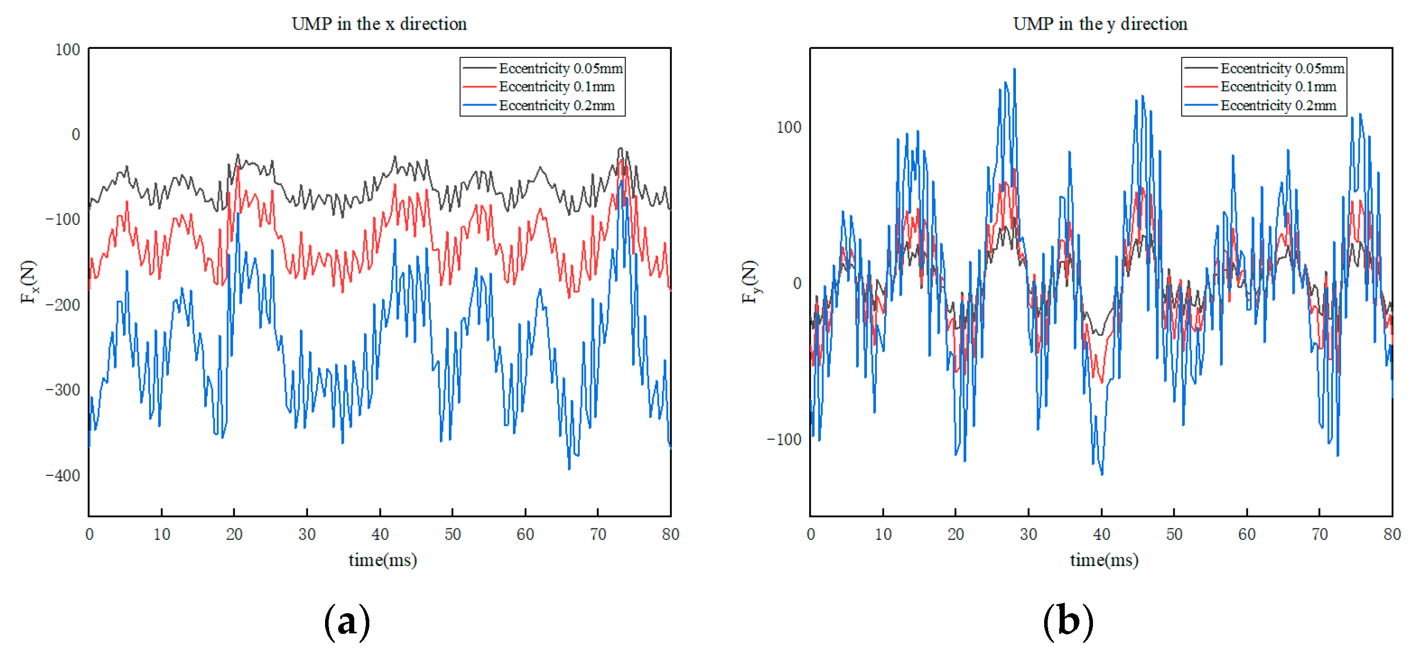
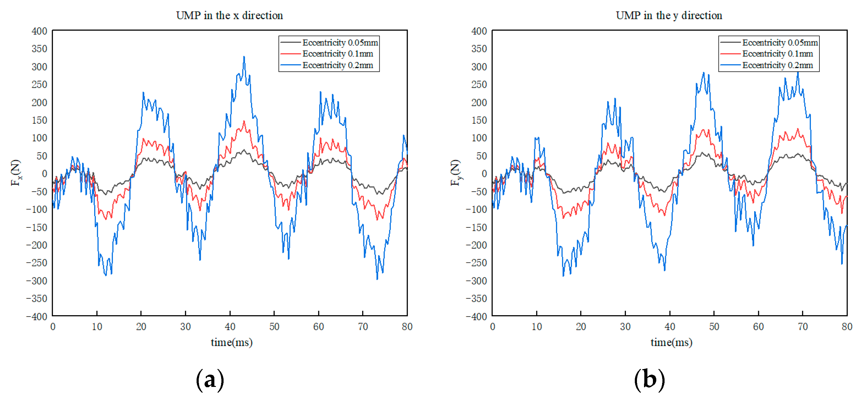
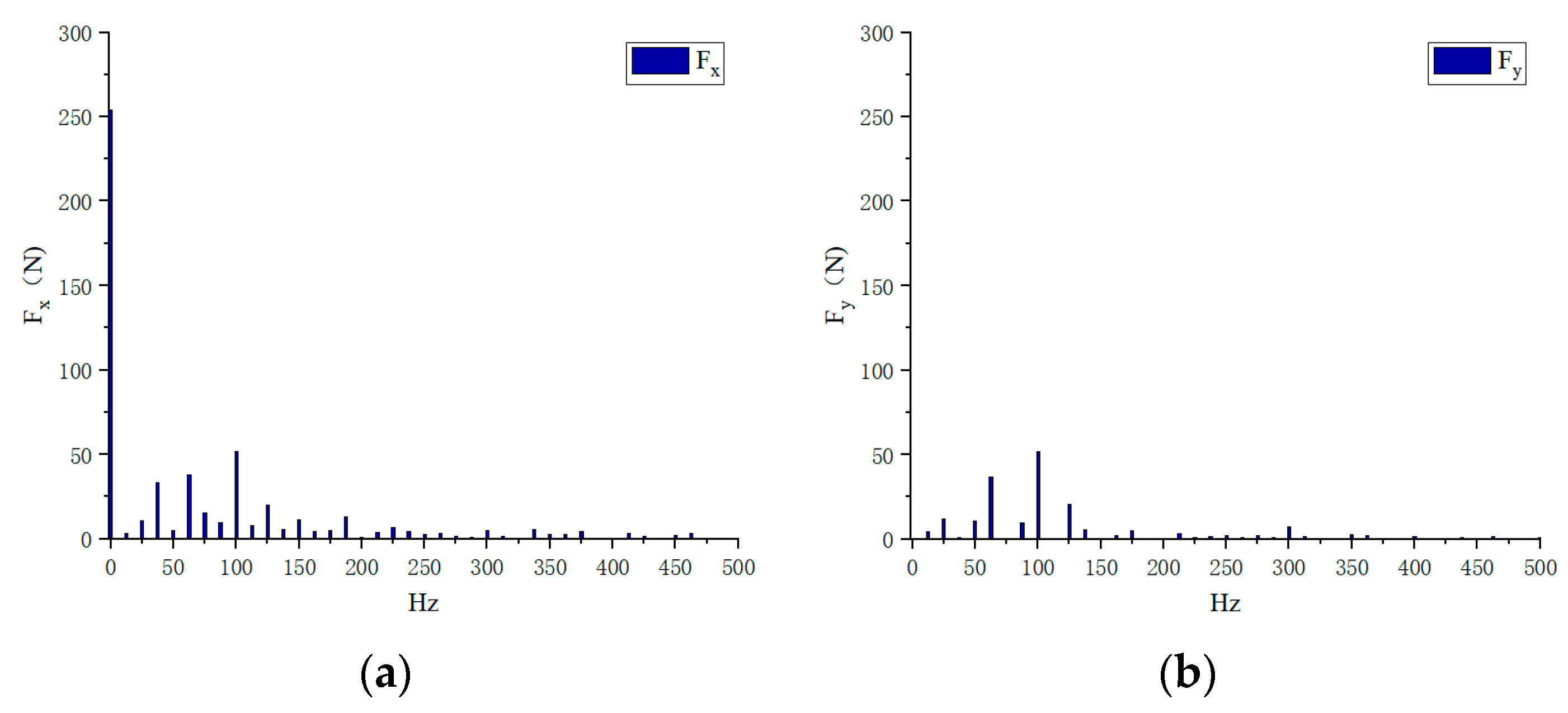
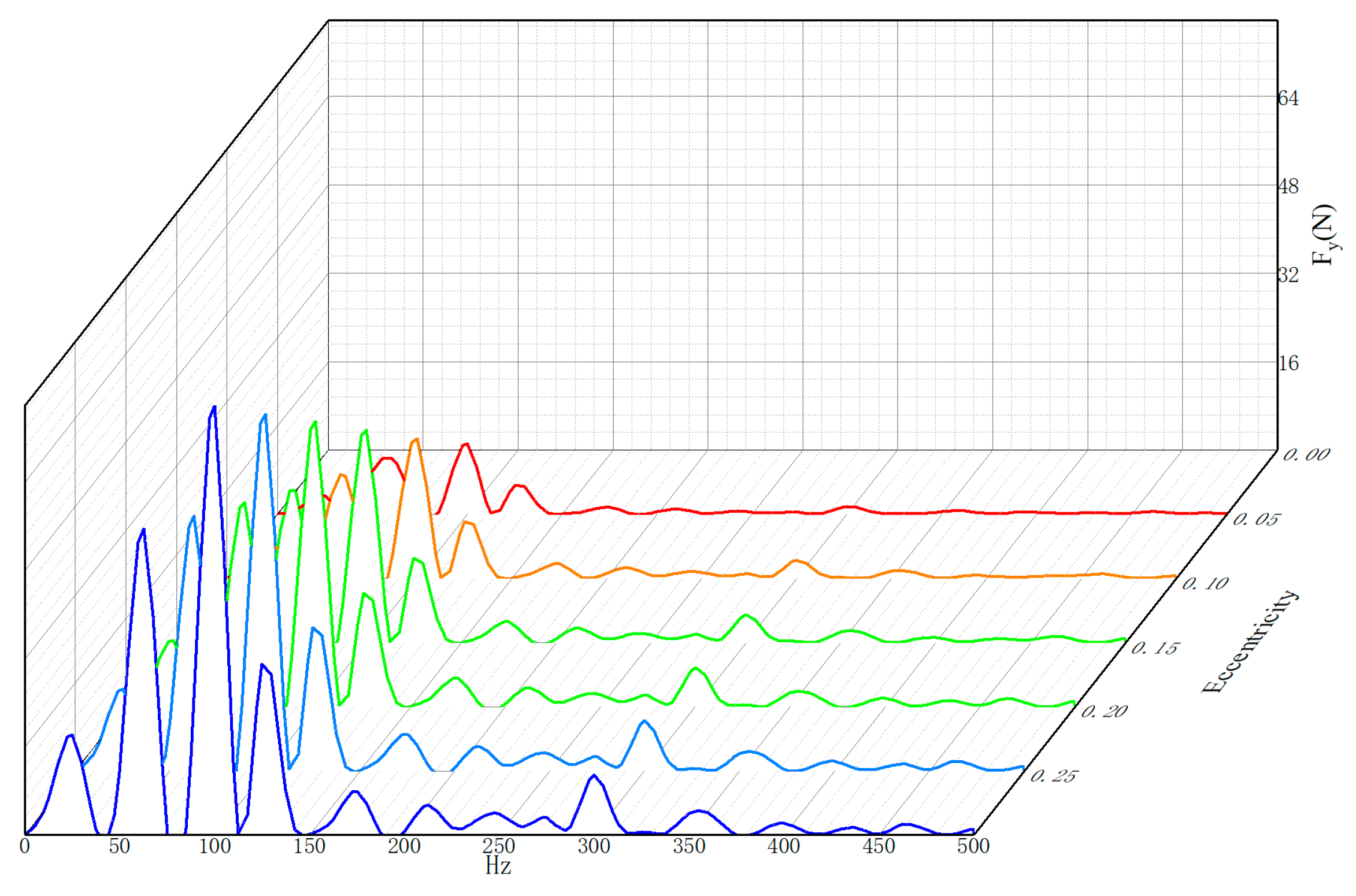
UMP of rotor under static air gap eccentricity fault
Figure 8. (a) Time domain diagram of UMP in x direction (b) Time domain diagram of UMP in y direction under static eccentricity.
Sustainability 15 08537 g008
Although the magnetic tension of the zero frequency component will not affect the rotor vibration, the zero frequency component always produces a magnetic tension pointing to the minimum air gap, increasing the deflection of the rotor by the magnetic tension.
It can be seen from Equation (11) that when angle γ is 0°, f 1 sin γ is 0. Therefore, there is no zero frequency component in the y direction. In Figure 4b, it can be seen that the UMP in the y direction fluctuates up and down along the x-axis. The amplitude of UMP increases with the increase in eccentricity.
It can be seen from Figure 9a that under the static eccentricity of the air gap, the frequency components of UMP in the x direction not only have zero frequency and twice the electrical frequency components, but also have fractional frequency components, and the zero frequency components are much larger than other frequency components. As can be seen in Figure 9b, the zero frequency component disappears, the frequency component is twice the electrical frequency (100 Hz), and the fractional frequency component near 100 Hz is the most concentrated.
Eccentricity refers to the ratio of eccentric distance to air gap length under normal conditions. Figure 10 is the waterfall diagram of UMP under different eccentricity in y direction. It can be seen from the figure that with the increase in eccentricity, the twice electric frequency component increases, and other harmonic components also increase. The energy is mainly concentrated near the twice electric frequency component.
Figure 11 shows the time domain waveform of UMP in x and y directions under rotor dynamic eccentricity fault. The red, green and blue curves represent the UMP under dynamic eccentricity of 0.05 mm, 0.1 mm and 0.2 mm, respectively. It can be seen from Figure 11 that the x direction and y direction components of the UMP under the air gap dynamic eccentricity fault fluctuate up and down along the x-axis. At this time, the zero frequency components in both directions disappear. As same as air gap static eccentricity fault, amplitude of the UMP increases with the increase in the eccentricity.
It can be seen from Figure 12a,b that the amplitude of UMP in the x and y directions is dominated by the frequency conversion component and there is a fractional frequency component, in which a quarter of the fractional frequency is the main component.
(3)
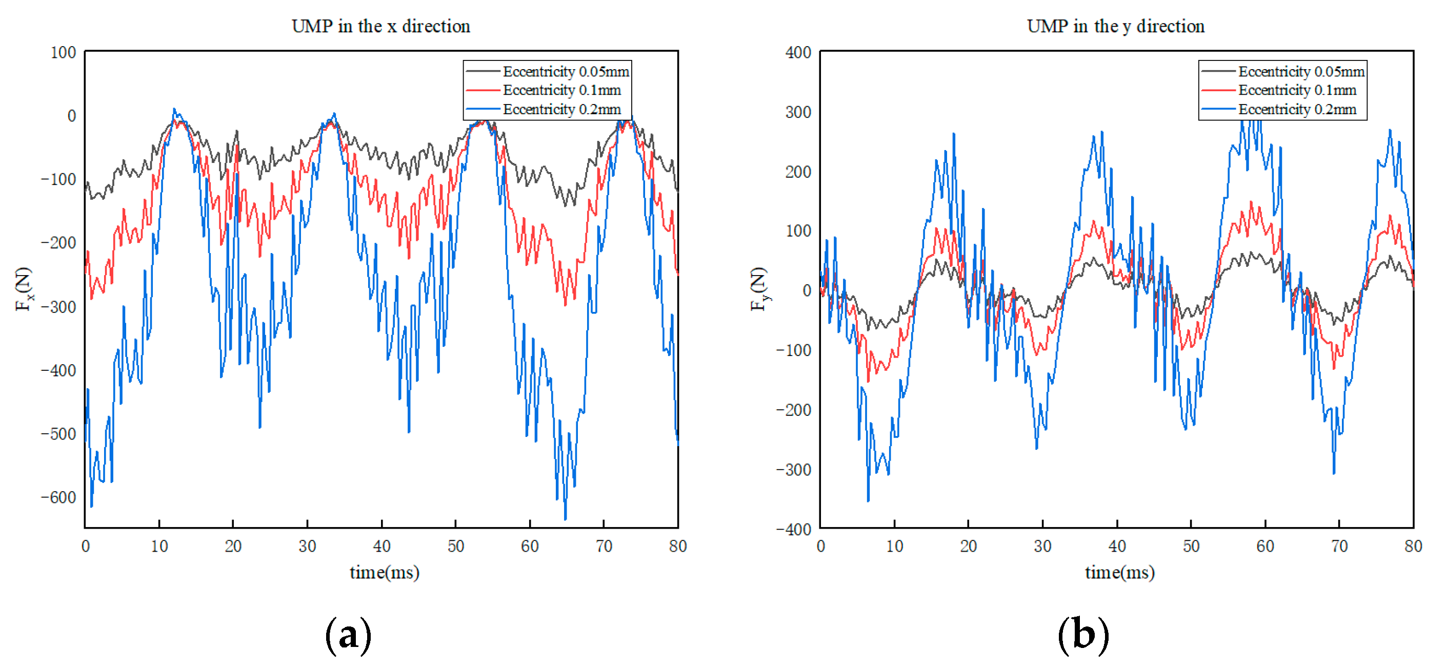
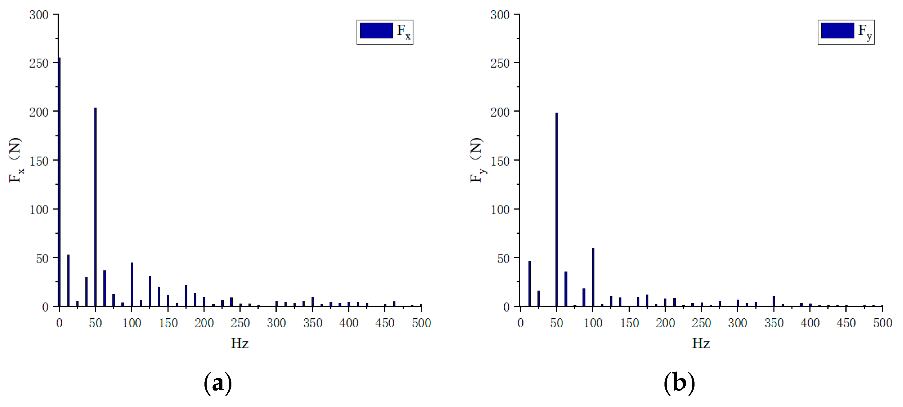
UMP of rotor under dynamic air gap eccentricity fault
Figure 11. (a) Time domain diagram of UMP in x direction (b) Time domain diagram of UMP in y direction under static eccentricity.
Sustainability 15 08537 g011
Figure 12. (a) Spectrum of UMP in x direction (b) Spectrum of UMP in x direction of dynamic eccentricity = 0.2 mm.
Sustainability 15 08537 g012
By comparing Figure 12a,b, it can be seen that the amplitudes of various frequency components are basically consistent, with only a small deviation.
Figure 13 is the time domain diagram of UMP under the fault of static and dynamic mixed air gap eccentricity. Black, red and blue lines represent the time domain waveform of UMP with the mixed eccentricity of 0.05 mm, 0.1 mm and 0.2 mm, respectively.
(4)
UMP of rotor in case of static and dynamic mixed air gap eccentricity fault
Figure 13. (a) Time domain diagram of UMP in x direction (b) Time domain diagram of UMP in y direction under mixed eccentricity.
Sustainability 15 08537 g013
The eccentricity in the mixed eccentricity represents that static eccentricity and dynamic eccentricity exist at the same time, and the eccentricity has moved the same distance. Figure 13a shows that the time domain diagram of UMP is all below the x-axis, and there is an obvious zero frequency component. As can be seen from the 13b diagram, the waveform of the time domain diagram of UMP changes periodically around x cycles.
Figure 14 is the UMP spectrum diagram in x and y directions under the rotor dynamic and static mixed air gap eccentricity of 0.2 mm. It can be seen from Figure 14a that the UMP in the x direction is dominated by zero frequency and frequency conversion components, and there are two times of electrical frequency components and fractional frequency components at the same time. The amplitude of one quarter of the fractional frequency is greater than the amplitude of two times of electrical frequency. It can be seen from Figure 14b that there is no zero frequency component in the y direction, and the frequency component is mainly frequency conversion. At this time, the twice electric frequency component is greater than the quarter frequency component. By comparing each frequency component in the two directions, there is a certain difference between the amplitude of the same frequency component in the x direction and the y direction, which is different from that when there is only static eccentricity fault.

3.3. Comparison of Two Calculation Methods

The main frequency components of unbalanced magnetic pull obtained by numerical calculation and finite element calculation were 0 Hz, 50 Hz and 100 Hz. Therefore, this section compared and verified the unbalanced magnetic pull at these three frequency components, adopting 0.2 mm eccentricity.
It can be seen from Table 2, Table 3 and Table 4 that the UMP size of numerical calculation and finite element calculation is close, which verifies the accuracy of theoretical calculation. Differing from numerical calculation, the finite element has more fractional frequency components, which is caused by omitting the higher-order air gap permeability series in numerical calculation.
(1)
Air gap static eccentricity
Table 2. UMP comparison with static eccentricity of the air gap.
Method0 Hz50 Hz100 Hz
Energy method261.1 N15.3 N62.3 N
Finite element calculation258.3 N6.1 N61.2 N
(2)
Air gap dynamic eccentricity
Table 3. UMP comparison with dynamic eccentricity of the air gap.
Method0 Hz50 Hz100 Hz
Energy method0 N210.2 N0 N
Finite element calculation0 N208.6 N5.3 N
(3)
Air gap dynamic and static mixing eccentricity
Table 4. UMP comparison of air gap dynamic and static mixing eccentric.
Method0 Hz50 Hz100 Hz
Energy method262.3 N210.5 N62.3 N
Finite element calculation259.8 N208.6 N61.5 N

4. Conclusions

This paper summarized the calculation methods of UMP suffered by the rotor under an air gap eccentric fault, including mainly the linear calculation method and nonlinear calculation method. Among them, the nonlinear calculation method had higher accuracy when the air gap eccentricity was small; the accuracy of the nonlinear calculation method decreased when the eccentricity was large.
The nonlinear calculation method mainly includes the energy method and Maxwell stress integration method. The basic idea of both methods is to expand the air gap permeability series and omit the high-order part. At this time, the UMP calculated has a high accuracy. In this paper, the finite element method is used to calculate the UMP of the rotor under three kinds of faults: static air gap eccentricity, dynamic air gap eccentricity and dynamic static mixed eccentricity. The experiment shows that with the increase in eccentricity, the amplitude of UMP suffered by the rotor under the three eccentric faults also increases. When the motor has air gap static eccentricity, the UMP is mainly composed of zero frequency components and twice the electrical frequency components, and there are low fractional frequency components and high fractional frequency components at the same time. The influence of the eccentric angle on the UMP in the x direction and y direction was compared. The conclusion shows that when the eccentric angle is consistent with the x direction, the zero frequency components will only exist in the direction, while the components in the y direction will disappear. When the motor has dynamic air gap eccentricity, the UMP received by the rotor is mainly a frequency conversion component, while there is fractional frequency component. When the motor has static and dynamic eccentricity at the same time, the UMP suffered by the rotor is mainly composed of zero frequency, rotational frequency and twice the electrical frequency, and there is also a fractional frequency component. However, at this time, the magnetic pull amplitude at the same frequency in the x and y directions is different, which is due to the fact that the two types of eccentricity faults increase the nonlinearity of the system at the same time, which will also reduce the stability of the rotor system. The reliability of UMP calculation is verified by comparison between numerical calculation and finite element calculation.

Author Contributions

Conceptualization, R.Z. and X.T.; methodology, X.T.; software, X.T.; validation, K.H., Q.H. and R.Z.; formal analysis, X.T.; investigation, X.T. and X.W. (Xinrou Wang); resources, R.Z.; data curation, X.T.; writing—original draft preparation, X.T.; writing—review and editing, R.Z.; visualization, R.Z.; supervision, X.W. (Xuechao Wang) and R.Z.; project administration, R.Z.; funding acquisition, R.Z. All authors have read and agreed to the published version of the manuscript.

Funding

This research was funded by [National Natural Science Foundation of China] grant number [12172210], and Science and Technology Commission of Shanghai Municipality (19DZ2271100).

Institutional Review Board Statement

Not applicable.

Informed Consent Statement

Not applicable.

Data Availability Statement

Data can be obtained through the following link: http://pan.baidu.con/s/1oBmfqwlfSg210D6a6S2haw, and it’s extracted code is “gexx”.

Acknowledgments

This work was financially supported by the National Natural Science Foundation of China, and Science and Technology Commission of Shanghai Municipality.

Conflicts of Interest

The authors declare no conflict of interest.

References

  1. Xu, X.P.; Han, Q.K.; Chu, F.L. Electromagnetic vibration characteristics of eccentric rotor under static load. J. Tsinghua Univ. (Nat. Sci. Sect.) 2016, 56, 176–184. [Google Scholar]
  2. Wan, S.T.; Peng, B. Distinction of electromagnetic torque characteristics between air gap static eccentricity and rotor interturn short circuit. J. Chin. Eng. Mach. 2021, 19, 65–71. [Google Scholar]
  3. Bao, X.H.; Lv, Q. Review and Prospect of Research on Air Gap Eccentricity Fault of Induction Motors. J. Chin. Electr. Eng. Sci. 2013, 33, 93–100 + 14. [Google Scholar]
  4. He, Y.L.; Wan, S.T.; Tang, G.J.; Xiang, L. Research on identification method of air gap eccentricity fault degree of turbo generator based on stator vibration characteristics. J. Vib. Shock 2012, 31, 53–57 + 89. [Google Scholar]
  5. Di, C.; Bao, X.; Wang, H.; Lv, Q.; He, Y. Modeling and Analysis of Unbalanced Magnetic Pull in Cage Induction Motors with Curved Dynamic Eccentricity. IEEE Trans. Magn. 2015, 51, 1–7. [Google Scholar]
  6. Zhou, S.T.; Guo, W.N.; Xiao, Q.; Zhu, J.; Zhou, X.; Tu, W. Analysis on vibration characteristics of traction motor rotor of EMU under eccentricity fault. Eng. Mech. 2021, 38, 216–225. [Google Scholar]
  7. Di, C.; Petrov, I.; Pyrhonen, J.J.; Bao, X. Unbalanced Magnetic Pull Compensation with Active Magnetic Bearings in a 2 MW High-Speed Induction Machine by FEM. IEEE Trans. Magn. 2018, 54, 194–201. [Google Scholar] [CrossRef]
  8. Zhou, S.T.; Zhu, J.W.; Xiao, Q. The influence of initial static eccentricity and gravity load on the rotor axis track of motor train traction motor. J. Mech. Eng. 2020, 56, 145–154. [Google Scholar]
  9. Wu, Y.C.; An, Q.F.; Ma, Q.Q.; Cai, Y.B. Research on unbalanced magnetic pull of typical electromechanical faults of hydrogenerator rotor. Hydropower Energy Sci. 2020, 38, 156–160. [Google Scholar]
  10. Chuan, H.; Shek, J.K.H. Mitigating Unbalanced Magnetic Pull in Induction Machines Using Active Control Method. IEEE Trans. Magn. 2021, 57, 172–179. [Google Scholar] [CrossRef]
  11. Zhang, L.; Yuan, Q.; Ma, X.; Hou, X.; Li, Z.; Zhang, J.; Wang, X. Study on Vibration Characteristics of Rotor Bearing System of Hydroelectric Generating Set Based on HB-AFT Method. J. Vib. Shock 2022, 41, 26–32. [Google Scholar] [CrossRef]
  12. Kumar, G.; Kalita, K.; Tammi, K. Analysis of Bridge Currents and UMP of an Induction Machine with Bridge Configured Winding Using Coupled Field and Circuit. IEEE Trans. Magn. 2018, 54, 8104416. [Google Scholar] [CrossRef]
  13. Feng, W.; Zhang, K.; Liu, B.G.; Sun, W.F.; Cai, S.J. Dynamic modeling and vibration response analysis of a synchronous motorized spindle with inclined eccentricity. J. Vib. Control 2021, 28, 2950–2964. [Google Scholar] [CrossRef]
  14. Guo, S.J.; Bai, C.Q. Coupling effect of unbalanced magnetic pull and ball bearing on nonlinear vibration of motor rotor system. J. Vib. Control 2020, 28, 665–676. [Google Scholar] [CrossRef]
  15. Li, X.W.; Bourdon, A.; Remond, D.; Koechlin, S.; Prieto, D. Angular-based modeling of unbalanced magnetic pull for analyzing the dynamical behavior of a 3-phase induction motor. J. Sound Vib. 2021, 494, 115884. [Google Scholar] [CrossRef]
  16. Hao, J.; Yao, Z.; Li, C.; Song, W.; Miao, H.; Xu, M.; Liu, Z. Dynamic characteristics analysis of asynchronous motorized spindle considering combined unbalanced magnetic pull and nonlinear bearing restoring force effects. Mech. Syst. Signal Process. 2022, 185, 109807. [Google Scholar] [CrossRef]
  17. Liu, F.; Xiang, C.L.; Liu, H.; Chen, X.; Feng, F.; Cong, H.; Yu, K. Model and experimental verification of a four degrees-of-freedom rotor considering combined eccentricity and electromagnetic effects. Mech. Syst. Signal Process. 2022, 169, 108740. [Google Scholar] [CrossRef]
  18. Chen, S.K. Motor Design, 2nd ed.; China Machine Press: Beijing, China, 2017; pp. 186–187. [Google Scholar]
  19. Lai, W.H.; Huang, K.S.; Zhou, Y. Analysis and calculation of eccentric electromagnetic force and deflection of permanent magnet synchronous motor rotor. Mot. Control Appl. 2022, 49, 74–79 + 95. [Google Scholar]
  20. He, Y.L.; Wang, F.L.; Tang, G.J. Influence of static eccentricity of generator air gap on electromagnetic torque. Vib. Test Diagn. 2017, 32, 76–81+217. [Google Scholar]
  21. Guo, D.; Chu, F.; Chen, D. The unbalanced magnetic pull and its effects on vibration in a three-phase generator with eccentric rotor. J. Sound Vib. 2002, 254, 297–312. [Google Scholar] [CrossRef]
Figure 1. Schematic diagram of air gap eccentricity between rotor and stator.
Sustainability 15 08537 g001
Figure 2. Single-disk rotor model.
Sustainability 15 08537 g002
Figure 6. Permanent magnet synchronous motor with single pair of magnetic poles.
Sustainability 15 08537 g006
Figure 9. (a) Spectrum of UMP in x direction (b) Spectrum of UMP in x direction of static eccentricity = 0.2 mm.
Sustainability 15 08537 g009
Figure 10. Waterfall diagram of UMP in y direction.
Sustainability 15 08537 g010
Figure 14. (a) Spectrum of UMP in x direction; (b) Spectrum of UMP in x direction of mixed eccentricity = 0.2 mm. From this, it can be seen that when dynamic and static eccentricity exist at the same time, such as the nonlinearity of the system increasing, and the stability of the rotor system decreasing.
Sustainability 15 08537 g014
Table 1. Parameter value.
ParameterNumerical Value
m (kg)24
k (N/m)1.526 × 107
C (N·s/m)200
L (m)0.1
R (m)5 × 10⁻²
μ0 (N/A2)4π × 10−7
Fj (A)30
ψ   (°)27.595
δ0 (m)1 × 10⁻³
Disclaimer/Publisher’s Note: The statements, opinions and data contained in all publications are solely those of the individual author(s) and contributor(s) and not of MDPI and/or the editor(s). MDPI and/or the editor(s) disclaim responsibility for any injury to people or property resulting from any ideas, methods, instructions or products referred to in the content.

