Article

Validation of a Contrail Life-Cycle Model in Central Europe

1
Institute of Logistics and Aviation, Technische Universität Dresden, Hettnerstr. 1-3, 01069 Dresden, Germany
2
Department of Air Transport, Czech Technical University in Prague, 166 36 Prague, Czech Republic
*
Author to whom correspondence should be addressed.
Sustainability 2023, 15(11), 8669; https://doi.org/10.3390/su15118669
Submission received: 17 April 2023 / Revised: 22 May 2023 / Accepted: 23 May 2023 / Published: 26 May 2023
(This article belongs to the Section Sustainable Transportation)

Abstract

:
In an industry beset by economic and environmental crises, air transport, the safest and most efficient long-haul mode of transport, is confronted daily with multi-criteria challenges to improve its environmental performance. The formation of contrails through the emission of water vapor and condensation nuclei in what are actually dry and clean atmospheric layers represents one of the most unpredictable, or measurable, environmental impacts of air traffic. Following the bottom-up principle to evaluate individual contrails in order to derive recommendations for trajectory optimization, not only the calculation of the radiative forcing of the contrails but also the modeling of their life cycle is burdened with uncertainties. In former studies for modeling the microphysical life cycle of contrails based on a 3-D Gaussian plume model, the atmospheric conditions, specifically the turbulence, were often unknown and had to be considered as a free input variable. In this study, an innovative photographic method for identifying and tracking contrails in Central Europe, connected with database access to Automatic Dependent Surveillance—Broadcast (ADS-B) data (i.e., aircraft type, speed, altitude, track, etc.), and a combination of measured and modeled weather data are used to validate the contrail life-cycle model (i.e., the assumed Gaussian plume behavior). We found that it is challenging to model the position of ice-supersaturated layers with global forecast models, but they have the most significant impact on the contrail lifetime. On average, the contrail’s lifespan could be modeled with an error margin of 10%. Sometimes, we slightly underestimated the lifetime. With the validated and plausible contrail life-cycle model, we can apply the climate effectiveness of individual contrails with higher certainty in trajectory optimization and compare it, for example, with economic aspects such as delay costs or fuel costs.

1. Introduction

One of the most unpredictable measurable environmental effects of air traffic is the formation of contrails, which are caused by the emission of water vapor and condensation nuclei [1,2]. Uncertainties plague both the calculation of the radiative forcing of individual contrails as well as the modeling of their life cycle when using the bottom-up principle to assess individual contrails in aircraft trajectory optimization.
Thereby, the atmospheric conditions, particularly the turbulence and the relative humidity, which have a substantial impact on the climate effect, often represent major uncertainty factors. In the search for additional sources of information, in addition to the global climate model, radiosondes provide a useful supplemental humidity database.
Often, contrails are approximated on a global scale as an infinitely extended cloud cover and are valued as having a high climate impact [3]. However, the impact of individual contrails on climate effectiveness may differ from global estimates. They may even produce a cooling effect on global warming depending on the lifetime and time of day [4]. This effect could be accounted for in trajectory optimization. Global contrail measurements (e.g., based on geostationary satellite images) average over real, individual contrails with different lifetimes at different time of day [5]. Although some of these contrails have a cooling effect, conditions of cooling contrails cannot be derived from these studies. However, before trajectories are re-optimized in the short term considering a possible contrail formation, we must be able to predict both lifetime and radiative properties with a high degree of certainty.
In this study, we focus on the estimation of the contrail lifetime. The contrail lifetime varies between seconds and hours and has an important impact on the contrail’s contribution to global warming. In general, the impact of a short-living contrail might be less crucial than the radiative impact of a long-living contrail. Therefore, a contrail life-cycle model [6] is validated using cameras for identifying and tracking contrails in Central Europe. In conjunction with database access to Automatic Dependent Surveillance—Broadcast (ADS-B) data (providing aircraft-type specific parameters, besides ground speed, altitude, track, etc.), an aircraft trajectory model (providing True Air Speed (TAS), thrust, and fuel flow) and a combination of measured and modeled weather data, the validity of the microphysical contrail life-cycle model is proven and the most important input variables are identified.
Many studies on the life cycles of contrails examine their effect on a global scale [7,8,9,10,11,12]. The development and lifespan of individual contrails play a subordinate role and are strongly abstracted. In addition, there are different ways to analyze the contrail life cycle. First, satellite observations can be used. This method is only possible when the contrail is fully developed, i.e., in the dissipation regime [7,8]. Especially, when contrails are detected automatically, satellite observation is only valid as long as the contrail constitutes a line-shaped artificial cirrus cloud in the atmosphere [9,10,11,12].
Wang et al. [13] additionally investigated the microphysical properties of satellite-observed contrails. Their measurements and comparisons of effective radius, particle number density, and optical thickness between contrails, contrail cirrus, and natural cirrus based on in-situ measurements result in smaller particle radii in contrails than in natural cirrus. A second assessment technique uses microphysical models. For example, the Contrail Cirrus Prediction Tool (COCiP) describes the individual contrail life cycle as a Lagrangian Gaussian plume [14]. Here, averaged contrail particle properties are described neglecting interaction with meteorology [14,15]. Although, in 2007, detailed observations and the identification of numerous variables on contrail lifetime and its optical properties (such as local wind speeds, humidity values, and wind shear) were published by Schumann and Heymsfield [15], these dependencies are not considered in COCiP. COCiP aims at short computation times and a reduced number of input variables.
Not primarily for the modeling of individual contrail life cycles, but for the approximation of typical lifetimes, very valuable are a few in-situ [16] and remote-sensing measurements [17] of contrails, yielding promising results which can also be used for model validation. Therefore, a research aircraft was fitted with cloud microphysics probes and remote-sensing instruments, and flown in an ice-supersaturated region. The contrails were sampled at an age between 7 and 30 min. This period results from the following boundary conditions: After 7 min at the latest, the ice particles have reached the critical size to be observed well. After 30 min, typical mid-latitude contrails are no longer present. The location, the contrail size, and some optical properties have been identified with in-flight Lidar measurements, which worked better than measurements with a shortwave spectrometer. Later, the contrail life cycle was modeled and compared with the UK Met Office NAME III climate model [18]. Even though these measurements are certainly very informative, their effort does not allow long-term measurements to cover as far as possible all the atmospheric conditions that have an influence on the contrail lifetime.
From this literature review, it follows that the determination of the Contrail lifetime and its microphysical properties depend on various highly variable, non-continuous atmospheric properties, which are difficult to measure and predict. For this reason, most studies are limited to determining averaged or typical lifetimes. On the other hand, global observations can track the entire contrail evolution and aviation-induced cloudiness which is no longer linear in shape. We address the challenge of determining the atmospheric state as precisely as possible using different data sources and then calculating the lifetime based on purely physical laws.

2. Methodology

Since the contrail life-cycle model requires different types of input data from various sources, a procedure for coupling those sources was developed and is summarized in Figure 1.
The photographic detection of a contrail and its storage in a contrail list (see 1. in Figure 1 and Section 2.1) serves as a trigger to start the following sequence: First, the inducing aircraft is identified by the hexadecimal aircraft address and is listed in a flight list (see 2. in Figure 1). The aircraft altitude and ground speed are determined using ADS-B data extraction (see 3. in Figure 1 and Section 2.2). Second, depending on date and time, the corresponding radiosonde humidity measurements are stored in a list (see 4. in Figure 1) and the modeled atmospheric humidity is replaced by radiosonde humidity measurements (see 5. in Figure 1 and Section 2.3). Third, after estimating the atmospheric turbulence (see 6. in Figure 1) and proving contrail formation in flight performance model (see 7. in Figure 1), the contrail lifetime is calculated (see 8. in Figure 1 and Section 3). Finally, the calculated lifetime is compared to the photographically measured one (see 9. in Figure 1 and Section 4).
For persistent contrail formation, two criteria have to be fulfilled: the Schmidt–Appelman criterion [19] and an ice-supersaturated atmosphere [20]. Since the Schmidt–Appelman criterion depends on the aircraft’s flight performance (i.e., thrust, TAS, and fuel flow), at the beginning of the sequence, the analytical flight-performance model SOPHIA [4] is used for recalculating every single flight and identifying time steps with contrail formation at the observation point (Section 2.4).
In the following, each sub-process is described in detail.

2.1. Ground-Based Photographic Contrail Detection

The ground-based contrail detection took place in the city of Děčín (50°46′44.364″ N; 14°12′57.672″ E) located approximately 80 km northwest of Prague, Czech Republic. The intention was to eliminate the influence of descending or climbing on flight performance and, therefore, the airspace around Děčín where aircraft usually fly at cruise flight level was chosen. The system installed at that location consists of three video cameras pointing upwards to the monitored part of the airspace which automatically records and saves video files during the set period. The limitation of the system is the impossibility of observing contrails during cloudy days, as they are formed above natural cloudiness, and during the night.
Saved recordings were then processed to detect contrail formation and to measure contrail lifetime. The lifetime was measured until contrail diffusion (compare Section 3.2) or until the contrail drifted away from the field of view due to wind. There were no problems with the short-lived contrails’ lifetime measurement but for the longest ones, it was sometimes not possible to obtain the exact lifetime because after some time the observed contrail was either covered by natural cloudiness or drifted by the wind out of the camera cone of view. For this study, we only analyzed contrails whose complete diffusion took place within the camera field of view. The procedure is described in detail in [21].
The output of this sub-process is the time and location of contrail formation (required for ADS-B-based flight and aircraft identification and for the EUROCONTROL database for estimating the origin and destination of the flight) and measured lifetime.

2.2. Aircraft/Flight Identification and ADS-B Data Extraction

In order to determine the aircraft responsible for contrail formation and gather relevant flight data, we relied on primary-source data transmitted by aircraft on the 1090 MHz frequency. This data includes Mode S messages, which encompass ADS-B messages and responses to Mode S Secondary Surveillance Radar interrogations. These data are passively received by a set of Radarcape receivers located in Prague and subsequently processed by a created script. First, the data are filtered by time according to the period the camera system was turned on and by aircraft position obtained from ADS-B messages to ensure we obtained only data from aircraft that flew through the monitored part of airspace in the output. The following steps include decoding and saving selected data to obtain only flight data relevant to our research such as altitude, speed, and heading. The International Civil Aviation Organization (ICAO) hexadecimal aircraft address serves as a unique identifier according to which all filtered and decoded data are assigned to individual aircraft records [21].
Acquired aircraft records were then assigned to observed contrails from the previous part. The contrail–aircraft pairing process is based on time and position comparison. The time of contrail detection is compared to the time when the aircraft entered the monitored part of the airspace according to ADS-B data and the location of the detected contrail on video recording is compared to the position (flight path) taken from ADS-B.
As a result, we obtained ICAO hexadecimal address (based on which it is possible to assign a type of aircraft) and position, altitude, and ground speed obtained from ADS-B messages, and heading, Mach number, and sometimes TAS obtained from replies to the interrogation of Mode S Secondary Surveillance Radar for each detected contrail.

2.3. Weather-Data Sources

2.3.1. Aircraft Meteorological Data Relay (AMDAR)

For safe flight operation, atmospheric state parameters, such as pressure and temperature, are frequently measured by aircraft in flight [22]. These data are transmitted to a receiving AMDAR station on the ground. Airlines, weather services, and other users receive the data after it has undergone data analysis, cleaning, and post-processing [23]. Compared to modeled weather data or radiosonde measurements, weather data collected from aircraft provides significantly higher temporal and spatial precision, particularly in areas with heavy aviation traffic [24]. However, aircrafts operated by European airlines do not measure the relative humidity, which is crucial for the decision of contrail formation and for calculating the contrail life cycle. In the United States, many aircrafts are equipped with humidity sensors and the data is available for research [25,26]. In Europe, only a few timely restricted measuring campaigns during cruise flights exist. For example, in 2005 and 2006 the WVSS-II aircraft-based humidity sensor from Spectra Sensors Inc. in the United States was tested on a portion of the global AMDAR fleet [27]. Besides 25 Boeing 757 aircrafts in the United States, three Lufthansa Airbus A319 aircrafts in Europe were equipped with the WVSS-II and the water-vapor mass mixing ratio output was included in the AMDAR data flow [27]. It is anticipated that aircraft-based observations will complement and, to some extent, replace existing radiosonde sounding systems once water-vapor measurement is added to AMDAR-capable aircrafts. Today, however, the onboard humidity measurement and data transfer are still too expensive and restricted to nine Lufthansa aircrafts which are measuring humidity during climb and descent, not during cruising. Furthermore, measurements during cruising in low humidities might be of low quality. The optical sensor WVSS-II might not be optimal for low-humidity values [27]. Soon, the German weather data service Deutscher Wetterdienst (DWD) will start a project which includes a quality check of continuous AMDAR humidity measurements with WVSS-II. Those measurements are organized by the DWD and the airline is only operating the aircraft. For this reason, the data is not publicly available.
Additionally, in the framework of the In-service Aircraft for a Global Observing System (IAGOS) program, a European research infrastructure which is part of the European Strategy Forum for Research Infrastructures (ESFRI Roadmap) [28,29], 20 long-range Airbus A330/340 aircrafts are performing continuous measurements of major reactive and greenhouse gases, including humidity. IAGOS has the capability to swiftly transmit its globally collected data to weather services and research institutes, enabling them to promptly incorporate this data into weather predictions and integrate it into their research endeavors.

2.3.2. Radiosonde Humidity Measurements

Another important weather-data source is radiosonde soundings, which are released daily, up to four times a day (but usually every twelve hours), all over the world. The measurements are publicly available and provided by the University of Wyoming [30] and by National Oceanic and Atmospheric Administration (NOAA) [31]. Every second of the measurement, the weather balloon measures the atmospheric state variables, wind, and humidity. At the same time, it ascends to the stratosphere until the balloon bursts and the equipment falls to the ground. According to experts from the DWD, the capacitive humidity sensors equipped with the radiosondes are more precise, even in low-humidity environments and in ice-supersaturated environments. For example, the radiosonde RS92SGP, as used three times a day in Prague with the THIN-FILM CAPACITOR humidity sensor, has an accuracy between 2% and 4% [32]. Those measurements reflect a standard used in climate models as well as for regional daily weather predictions. An example measurement is shown in Figure 2, right.

2.3.3. Modelled Weather Data

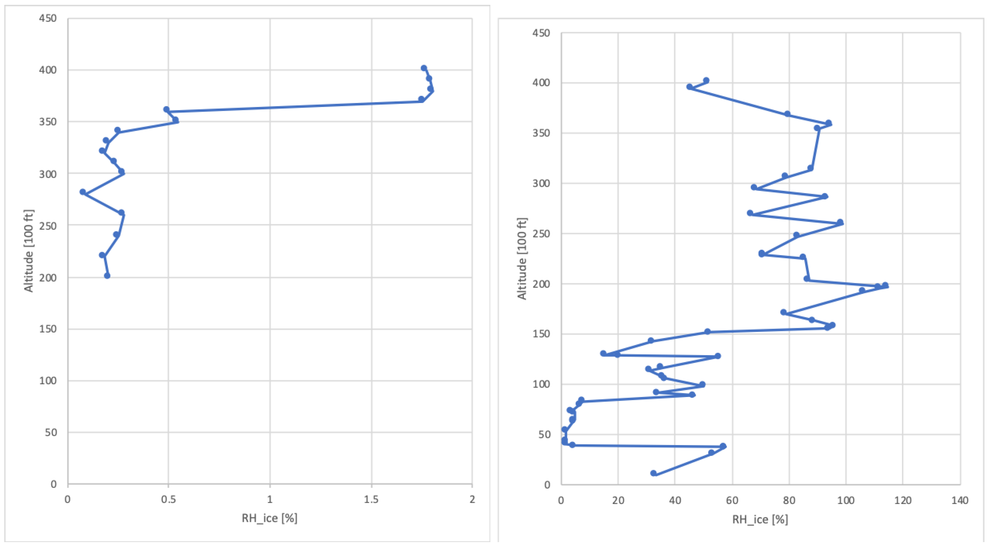
In studies where 4-D weather is considered in aircraft trajectory optimization, usually, numerical weather models, such as the Global Forecast System (GFS) published by the NOAA, provide reliable data sets with sufficient temporal and spatial resolution [33]. Those models assimilate AMDAR and radiosonde data into continuous calculations of the current global atmospheric state. The GFS offers a binary-coded global weather-data set every six hours. The information is compressed into a file with a maximum size of 16 Mb called GRIdded Binary (GRIB2). Additionally, the National Weather Service (NWS) of the NOAA forecasts the global weather with different time horizons. Furthermore, to determine the degree of uncertainty in an GFS forecast, the National Centers for Environmental Prediction (NCEP) provides 21 Global Ensemble Forecast System (GEFS) ensemble forecasts. The analysis of these ensembles and forecast accuracy is found in [34]. Although those models are frequently pushed by real measurements of radiosondes, the uneven distribution of measuring stations and the high volatility of some atmospheric state variables lead to errors in individual data sets in some places. This source of error is amplified by a relatively coarse spatial resolution in the vertical direction. This means that at flight level (around 200 hPa), the model issues a new weather-data set at intervals of 50 hPa. This uncertainty often concerns relative humidity profiles [33]. For this reason, long-living contrails might be detected at times and locations where GFS does not indicate ice supersaturation (see an example from 26 September 2019 in Figure 2). In this case, a calculation of the contrail life cycle is not possible with the provided GFS data. Therefore, we replaced the modeled relative humidity with the measured humidity profile.

2.4. Aircraft Performance Model

While we assume that every flight identified in Section 2.2 produces a contrail, we verified the atmospheric conditions and flight performance of each flight to confirm this assumption. We recalculated each flight using the aircraft-type-specific kinetic model Sophisticated Aircraft Performance Model (SOPHIA) to generate a precise vertical profile. This is necessary because the criteria for contrail formation and the initial state of the contrail are dependent on the flight performance. SOPHIA is embedded in the TOolchain for Multi-criteria Aircraft Trajectory Optimization (TOMATO) [35,36]. In this study, SOPHIA is used to model an optimal vertical profile (i.e., climb and descent rates according to minimum fuel burn) considering cruising altitudes identified in Section 2.2. The lateral path was calculated by the path-finding algorithm of TOMATO considering all waypoints identified in Section 2.2. The state variables v TAS , pressure altitude p (Pa), and flight path angle γ were calculated for each time step by SOPHIA using analytical functions. Nevertheless, for speed with minimum fuel, an analytic solution cannot be obtained; thus, Brent’s method [37] was used to compute these particular speeds. In an aircraft-type-specific proportional-integral-derivative controller (PID controller), v TAS , target , p target , and γ target were employed as controlled variables and the lift coefficient c L was used as regulative variable [4]. Aircraft-type-specific parameters for the drag polar depending on the flap handle position, and the engine thrust depending on the throttle parameter or defined ratings, were taken from the Open Aircraft Performance model (OpenAP) [38]. Fuel burn and engine emissions (for environmental costs) were quantified using a jet-engine combustion model [39].
Each time step (default 1   s ), the following state variables were calculated in the ground-based coordinate system including wind correction: true airspeed v TAS ( m   s 1 ), thrust F ( N ), fuel flow m f ˙ ( k g   s 1 ), forces of acceleration a x ( m   s 2 ) and a y ( m   s 2 ) for the derivation of v TAS , time of flight t ( s ), and emission quantities ( k g   s 1 ) [36].
For conditions of contrail formation, the slope G, describing the mixing of the engine emissions with the ambient air in an enthalpy-mass diagram [19]
G = Q ( 1 η ) E I water
was calculated. Here, Q = 43 MJ kg 1 denotes the specific combustion heat of the kerosene. E I water describes the emission index of water vapor ( kg kg 1 ). η defines the overall propulsion efficiency as the fraction between resulting energy (thrust F times true airspeed v TAS ) and required energy (specific combustion heat Q and fuel flow m ˙ f ) [19]
η = F v TAS Q m ˙ f .
Subsequently, the threshold temperature for contrail formation T LC was calculated iteratively as a function of the saturation vapor pressures e * ( T LM ) and e * ( T LC ) and the relative humidity of the ambient atmosphere r H E :
r H E = e E e * ( T LC )
Parameters of the empiric formulas of e * ( T ) (hPa) over flat water surfaces and ice were taken from Sonntag [40].
T LC = T LM e * ( T LM ) r H E e * ( T LC ) G .
A starting value for T LM was taken from Schumann 1996 [41]:
T LM = 46.46 + 9.43 ln ( G 0.053 ) + 0.720 ( ln ( G 0.053 ) ) 2 .
In cases when the ambient temperature T was below the critical temperature T LC and the atmosphere was supersaturated concerning ice, we assumed contrail formation at this specific time step and calculated the initial state of the contrail (as described in Section 3).

3. Contrail Life Cycle

Paugum et al. [42] describe the evolution of a young contrail in four phases: In the jet regime, two counter-rotating vortices enroll. These vortices form the primary wake. In the vortex regime, due to a large gradient in ambient density, the primary wake falls and generates a secondary wake. The aircraft emissions are captured between the continuously generated primary wake at flight altitude and the secondary wake below flight altitude. After about 100 s (in the following specified with the time t (s), estimated according to Holzäpfel et al. [43]), turbulence and exhaust gases leave the primary wake in the dissipation regime and both the primary and the secondary wake begin to decay. Only in an ice-supersaturated atmosphere, are the ice particles big enough to survive the dissipation regime. In the following hours, the diffusion of the exhaust takes place in the diffusion regime. The mixing of the emissions with the ambient atmosphere starts.
In this study, the dimension of the wake vortices at the end of the dissipation regime (defining the initial dimension of the contrail) were estimated with a probabilistic wake vortex model [43].
The duration of these regimes strongly depends on turbulence and on the circulation within the vortices, i.e., the aircraft mass m, true airspeed v TAS , and aircraft wing span l s (m). For example, behind an Airbus A320 aircraft the time t while the wake vortices are falling is between 40 and 58 s , depending on turbulence [6].
The turbulence intensity in the atmosphere is denoted by the turbulent energy dissipation rate ε ( m 2 s 3 ), defined as the conversion of kinetic energy due to molecular friction per unit mass and per time into thermal energy [44]. For ε , a lognormal distribution of turbulence in the lower troposphere and upper stratosphere is assumed [45]. Furthermore, a linear correlation between ε and the vertical velocity w (Pa s 1 ) [45], provided by the GFS as logarithmic diagnostic turbulence value [44,45], is considered in this study. More details on those assumptions can be found in [45,46].
ε 1 / 3 = a ε + b ε ln w ,
with
b ε = σ ( ln ε 1 / 3 ) σ ( ln w )
and
a ε = ln ε 1 / 3 b ε ln w .
In Equation (7), σ ( ln ε 1 / 3 ) denotes the standard deviation of all logarithmized eddy dissipation rate values. σ ( ln w ) denotes the standard deviation of all logarithmized vertical velocity values. Sharman et al. emphasize the necessity of sufficiently large range of ε and w [45,46]. The vertical velocity w (Pa s 1 ) is defined as the rate of change in pressure with time [47]
w = d p d t .

3.1. Dissipation Regime

At the beginning of the dissipation regime (≈70–100 s after contrail formation) the vortices descend with a descent speed v s ( m s 1 ) (Equation (10)) for a time t, once fully established [43]. The descent speed v s is normalized to the initial tangential velocity v t , 0 [43]
v s = v t , 0 1 exp 1.257 b 2 r c 2 ,
where b = 0.4 b 0 (m); b 0 = π 4 l s (m) denotes the effective horizontal vortex spacing and the initial horizontal vortex spacing between left and right vortex assuming an elliptical wing loading [48], respectively. The elliptical wing loading induces minimum drag and is a rather good assumption for modern aircraft design [49]. The radius of the vortex core depends on aircraft type and is estimated iteratively aiming to achieve an equally calculated initial contrail height compared to measurements by Sussmann and Gierens [50]. For example, r c = 0.09 l s for an A320 aircraft. The initial tangential velocity v t , 0 ( m s 1 ) within the vortices
v t , 0 = Γ 0 2 π b 0
depends on initial circulation Γ 0 ( m 2 s 1 ) of the wake vortex, i.e., the integral of the velocity along the circular path around the wing:
Γ 0 = v d s .
Following Equation (12), the circulation as the divergence of the velocity around the wing is always greater than zero. Hence, a lift force F L (N) develops. With the Kutta–Joukowski theorem [51], F L depends on
F L = ρ v TAS b 0 Γ 0 .
Assuming the aircraft to be in a vertical equilibrium where lift compensates weight ( F L = F G ) with F G = m g (N), Γ 0 is
Γ 0 = m g ρ b 0 v TAS .
The time t while the wake vortices descend during the dissipation regime depends on stratification (i.e., on normalized Brunt-Väisälä frequency N n = N t n )
t = t n ( N n = 0 ) exp [ 0.185 t n ( N n = 0 ) N n ] t n ,
with
t n = b 0 v t , 0
as normalized time scale (s). Note, normalized times can be transferred into aircraft-specific times by multiplication with t n . The time t n ( N n = 0 ) represents the descent time in a neutrally stratified atmosphere and depends on normalized eddy dissipation rate ε n
ε n = ( ε b 0 ) 1 / 3 v t , 0
with v t , 0 (m s 1 ) as initial tangential velocity and ε calculated according to Equation (6).
In Equation (15), t n ( N n = 0 ) depends on t n , 2 [43]
t n ( N n = 0 ) = t n , 2 1 ;
for ε n > 0.2535 , t n , 2 can be calculated using a model of Sarpkaya [52] modified by Holzäpfel et al. [43]
t n , 2 = 0.804 ε n 3 / 4 .
For 0.0235 < ε n < 0.2535 , the original formula of Sarpkaya [52] can be used:
ε n = t n , 2 1 / 4 exp 0.70 t n , 2 .
For ε n 0.0235 , Holzäpfel et al. [43] defined:
t n ( N n = 0 ) = 5 .
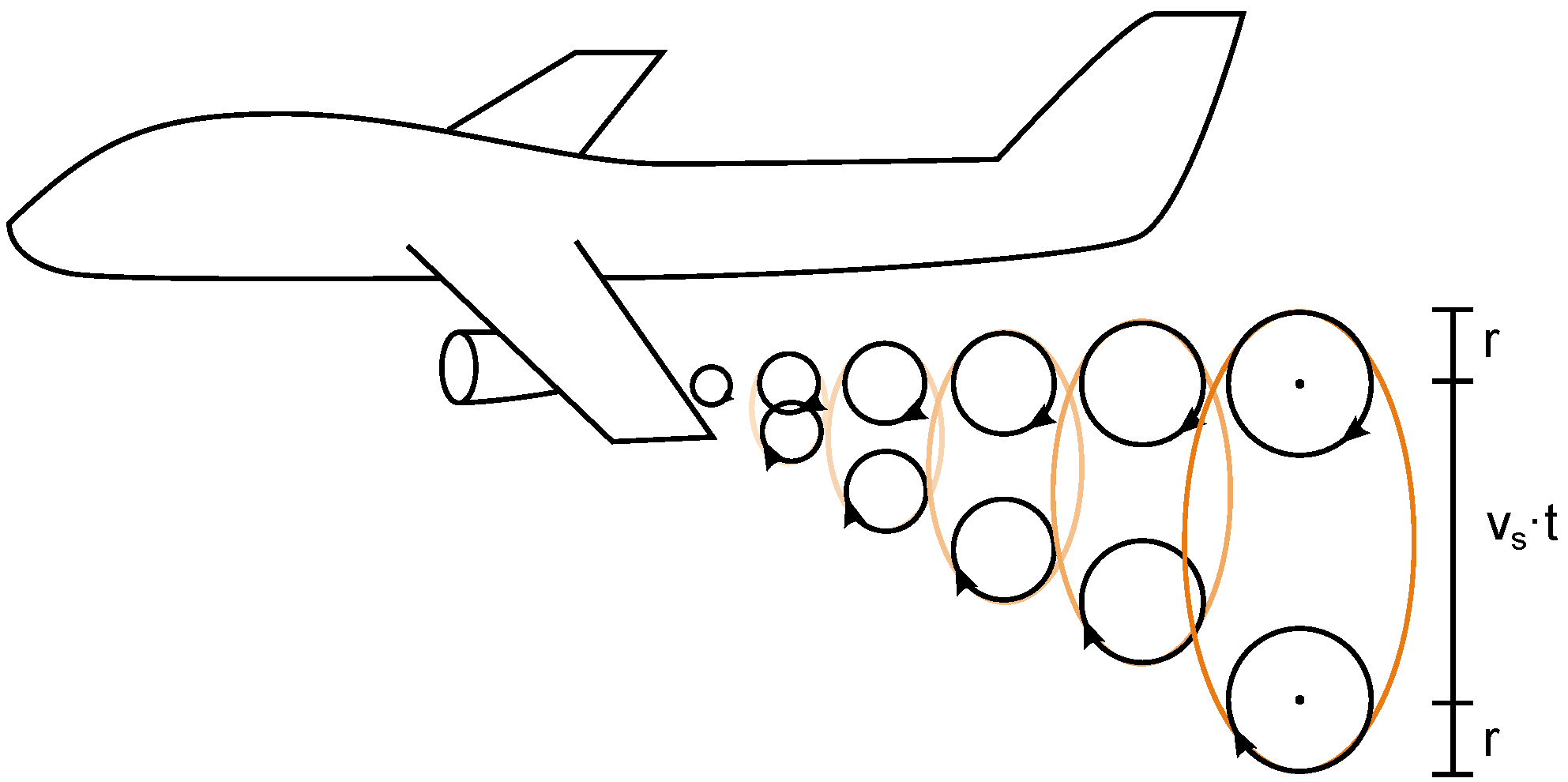
Finally, the initial vertical dimension of the contrail c v (m)
c v ( t ) = v s t + 2 r .
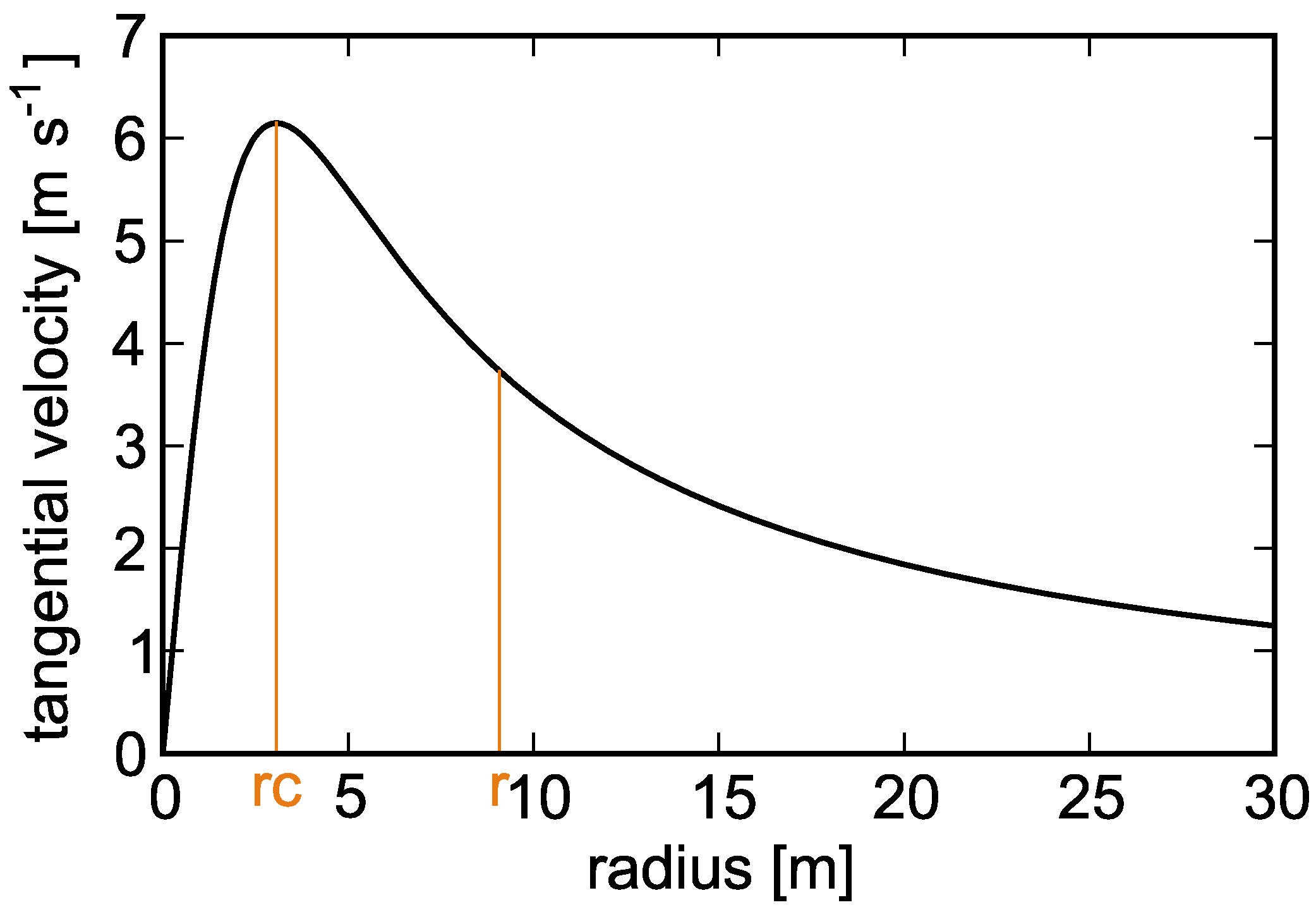
depends on vortex radius r (m). We assume a correlation between r and the tangential velocity v t ( r ) ( m s 1 ), as a measure of the ability of ice particles to follow the circular path within the wake vortices. The tangential velocity is defined as the cross product of the angular velocity ω and the radius r . According to Burnham et al. [53],
v t ( r ) = Γ 2 π r r 2 + r c 2
is maximal in the vortex core r c and decelerates with increasing radius r . In the diffusion regime, a Gaussian plume model was used, assuming that the growth in the contrail cross-section is represented by a sheared ellipse. Accordingly, a certain definition of the contrail boundaries is impossible, as the amount of ice particles among the ellipse is described by a Gaussian probability density function with infinite boundaries. The standard deviation σ describes the number of ice particles within a certain radius r : at 1 σ the distribution function reaches a value ( e ) 1 of the maximum value of the function. The vortex radius r is defined where tangential velocity v t ( r ) reaches the value ( e ) 1 . Consequently, tangential velocity v t is maximum at location r c
v t ( r c ) = Γ 4 π r c .
Hence, ( e ) 1 of v t ( r c ) is
v t ( r ) = 1 e Γ 4 π r c = Γ 2 π r r 2 + r c 2 .
The radius r is the larger value of the quadratic equation
r 2 e 2 r c r + r c 2 = 0 ,
which is
r = ( e + e 1 ) r c .
The estimation of r is demonstrated in Figure 3.
Figure 4 and Equation (22) demonstrate the initial vertical contrail height.
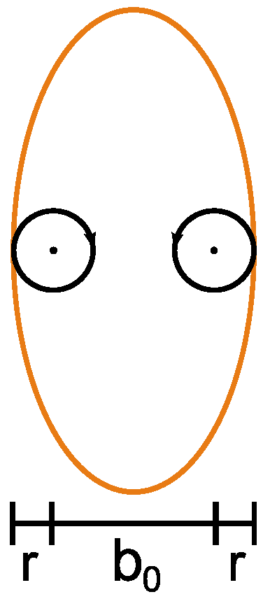
The horizontal dimension c h , i.e., the contrail width, is defined as the initial horizontal vortex spacing b 0 plus two times the vortex radius r (Figure 5).
c h = b 0 + 2 r .
Note, within the time span t until the end of the dissipation regime we neglect a horizontal spreading of the two vortices (which is valid for small values of Brunt-Väisälä frequency N and weak turbulence [54]).

3.2. Diffusion Regime

In the diffusion regime, wake vortices no longer define the contrail, since the circulation (which once trapped emissions inside) has degraded. The end of the lifespan of a contrail is determined by two factors: the air inside the contrail no longer being ice-supersaturated or the ice particles being too far apart from one another. At this stage, the radiative extinction of the ice particles becomes negligible. A Gaussian plume model is used to simulate the turbulent diffusion of the contrail until it is completely mixed with the atmosphere. Schumann et al. [55] demonstrate how a Gaussian plume model can be used to analyze contrails. For example, exhaust plumes from any industry utilizing fossil fuels are frequently calculated using the Gaussian plume model [44].
Applying the Gaussian plume model, the artificial cloud diffuses faster with increasing cross-section. Furthermore, the ice mass concentration decreases with distance from the center. Based on this supposition, vortex-centric ellipses with a constant ice mass are produced. The Ice Water Content (IWC) ( kg m 3 ) is used to express the entire quantity of ice mass per volume contrail. One standard deviation is used to define the location along the vertical and horizontal axes of a Gaussian distribution, with its highest value concentrated at ( e ) 1 in the center of the cross-section. The use of a two-dimensional Gaussian distribution is shown in Figure 6, which also defines the axes that are utilized in this model.
The two-dimensional probability density function that calculates the number of ice particles present in the contrail at any given time t (s) and the place are:
f ( x , t ) = 1 2 π det σ ^ ( t ) exp 1 2 x T σ ^ ( t ) 1 x .
x describes the position vector
x = y z
Two limiting parameters, I W C < 10 8 kg m 3 or r H ice < 100 % , are used to define the contrail lifetime [14]. The first instance is a hypothetical situation when a contrail becomes too thin optically to be seen as a contrail. The ice particles sublime in the second case, when the contrail drifts away from the ice-supersaturated environment.
The variance in the standard deviation σ ^ ( t ) (m 2 ) is described using a matrix of horizontal σ ^ h ( t ) (m), vertical σ ^ v ( t ) (m) and sheared σ ^ s ( t ) (m) components of the contrail’s diffusion.
σ ^ ( t ) = σ ^ h ( t ) σ ^ s ( t ) σ ^ s ( t ) σ ^ v ( t )
Following the definition of the area of an ellipse [14,56], the contrail cross-section A is defined as
A = 2 π det σ .
The initial standard deviations σ 0 h = 2.2 c h and σ 0 v = 2.2 c v are defined as starting values [55].
The development of the variances σ ^ h ( t ) , σ ^ v ( t ) , and σ ^ s ( t ) is [55]:
σ ^ h ( t ) = 2 3 s h 2 D v t 3 + ( 2 D s + s h σ 0 v 2 ) s h t 2 + 2 D h t + σ 0 h 2
σ ^ s ( t ) = s h D v t 2 + ( 2 D s + s h σ o v 2 ) t
σ ^ v ( t ) = s h D v t + σ o v 2 ,
where s h [ s 1 ]
s h = Δ v Δ z
denotes the wind shear as difference in wind velocity Δ v ( m s 1 ) between two altitudes Δ z (m) and is calculated with the GFS data. Wind shear strongly influences the 2-D sheared Gaussian plume model for contrail dispersion [6,57,58]. Δ z is called the shear layer and depends on the maximum differences in wind velocity between two altitudes. s h is calculated from the provided weather data. The sheared diffusivity D s (m 2 s 1 ) is assumed to be in the range of the square root of the vertical D v (m 2 s 1 ) and horizontal diffusivity D h (m 2 s 1 ): D s D v D h [55], but D s D v D h [6].
In Equations (33)–(35), D v , D h and D s are the components of an asymmetric and anisotropic diffusivity tensor:
D ^ = D h D s D s D v .
Typical values of D v , D h , and D s in a stably stratified atmosphere at flight level are provided by Schumann et al. [55]:
0 D v 0.6 m 2 s 2
5 D h 20 m 2 s 2
0 | D s | 2 m 2 s 2
| s h | 0.002 s 1
D s influences the horizontal D h and vertical D v diffusivity. According to a two-dimensional Fick’s law, D s 0 causes a composition wherein D h and D v slightly influence each other. For D s = 0.3 m 2 s 2 , a contrail lives approximately five hours shorter, in comparison with D s = 0 m 2 s 2 [6]. Wind-shear variations are more important. Particles develop more quickly and become larger at a constant wind shear of s h = 0.002 s 1 than for s h = 0 s 1 . The contrail cross-section grows more quickly in a sheared environment.
Following Equations (33)–(35), wind shear s h is equal to the vertical and horizontal components of the variance matrix σ ^ ( t ) and to the diffusivity tensor D ^ . However, the Gaussian plume model is very sensitive to sheared components. For values of D s D v D h the two-dimensional Gaussian distribution function results in a contrail cross-section converging to zero, until, for D s = D v D h , the Gaussian function describes no longer an ellipse, but a pair of parallel straight lines. In this case, the determinant det σ ^ = 0 and the contrail cross-section A is zero [56]. For D s > D v D h , the determinant det σ ^ becomes an imaginary number, and the area is not computable.
A linear correlation between ε and D v , D h is assumed (examples are provided in Table 1).
The vertical diffusivity
D v = c ε N 2 ,
depends on the eddy dissipation rate ε , Brunt-Väisälä frequency N and on a constant factor c = 0.1 [55].
Therefore, Equation (29) becomes:
f ( y , z , t , D v , D h , D s ) = 1 2 π det σ ^ ( t ) exp 1 2 det σ ^ ( t ) ( σ ^ v ( t ) y 2 + σ ^ h ( t ) z 2 ) .
The initial number of ice particles corresponds to the number of emitted (hydrophilic) soot particles. Assuming an emission index of soot E I soot = 0.04 g kg 1 kerosene [59], a density of soot ρ soot = 2 g cm 3 and a mean soot particle diameter d soot = 60 nm [60], the specific number of emitted soot particles is N ice = 10 15 per kg of combusted kerosene [20].
For the emission index of water vapor E I water , we assume lean combustion with more oxygen than necessary resulting in an emission index of E I water = 1.24 kg kg 1 [61].
Assuming a constant vapor pressure above ice and water, the relative humidity above ice is
r H ice = r H water e water * e ice * ,
where r H water is given by the radiosonde data. The ratio Δ e above saturation is assumed to be captured by the ice particles
Δ e = e ice * ( r H ice 100 1 ) .
Hence, the amount of water vapor I W C s contributing to the ice particle size is
I W C s = Δ e R v T ,
where R v = 461.5 J ( kg K ) 1 denotes the specific gas constant of water vapor. I W C s distinguishes from the total IWC because I W C s is the humidity, which is not necessary for saturation of the air within a contrail and, therefore, can be used for ice particle growth. The total IWC of the ice particles for a section of the contrail is defined by the distance s flown by aircraft in one second, estimated with the help of true airspeed v TAS ( m s 1 ) and the amount of combusted kerosine (the fuel flow m ˙ f ( kg s 1 ))
I W C = I W C s + E I water m f v TAS A .
The amount of available ice mass m ice (kg) within the volume defined by the contrail cross-section A and a contrail length s = 1 m
m ice = I W C · A · s
allows the calculation of the volume V p (m 3 ) of a spherical ice particle
V p = I W C N ice ρ ice ,
where ρ ice = 917 kg m 3 denotes the density of ice [62] and the volume of a sphere is
V p = π 6 d ice 3 .
Consequently, the initial mean crystal diameter is
d ice = 6 m ice π N ice 3 .

Contrail Drift

Additional to the growth in cross-section, the contrail is drifted by wind vertically and horizontally. The growth in the cross-section due to diffusion causes a reduction in its IWC [ kg m 3 ], as soon as the contrail leaves the ice-supersaturated layer. Each time step, the IWC is calculated. According to the Stokes law [63], every particle within the contrail experiences a drag force F W , p as a result of viscous friction:
F W , p = 6 π η dyn v s , p r p .
F W , p is equal to the weight F G , p of the particle
F G , p = 4 3 π r p 3 ρ p g ,
where v s , p ( m s 1 ) is the ice particle sedimentation speed, r p ( m ) the ice particle radius, ρ p ( kg m 3 ) the ice particle density, and η dyn [ kg m 1 s 1 ] the dynamical viscosity, respectively. The sedimentation speed v s , p comes from balancing Equations (52) and (53) [64]
v s , p = 2 r p 2 ρ p g 9 η dyn .
η dyn is calculated as the product of the density of the atmosphere ρ ( kg m 3 ) and kinematic viscosity ν kin ( m 2 s 1 ), which, in turn, is calculated according to Sutherland [65].
ν kin = ρ η dyn .
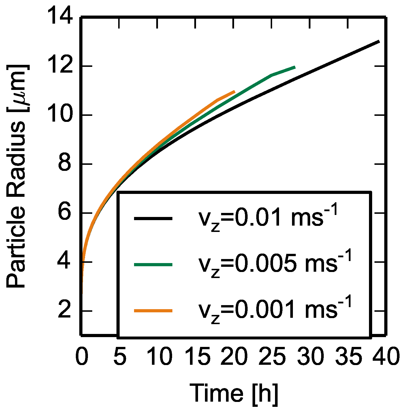
The sedimentation speed v s , p might be counteracted by a vertical movement due to (vertical) wind drift, which is provided by the GFS weather data. If an upwind exceeds the sedimentation speed, the particle will move upwards. For example, assuming an upward vertical wind speed of v z = 0.005 m s 1 , from Equation (54) follows sedimentation of the contrail into warmer and dryer altitudes in the atmosphere as soon as the ice-particle radius exceeds r p 6 μ m . The contrail heats adiabatically during this sedimentation, which sublimates ice particles, lowers relative humidity inside the contrail, and shortens the contrail’s lifetime overall.
The impact of vertical wind on ice-particle growth and on contrail lifetime is not negligible (see Figure 7). For example, for v z > 0.01 m s 1 , the contrail lives for an unrealistically long time. The lifetime and the development of the particle radius saturate at the level of v z = 0.001 m s .
Additionally, to the vertical movement, the contrail drifts horizontally and could leave the ice-supersaturated layer. Strong winds distort the contrail cross-section. The phenomenon is considered in turbulence-dependent diffusion. Therewith, the horizontal displacement simply follows the horizontal wind speed provided by the GFS weather data.

4. Results

4.1. Observed and Identified Aircraft with Contrail Formation

By applying the method for contrail detection and aircraft pairing, described in Section 2.1 and Section 2.2, within 68 randomly chosen days between September 2018 and July 2020, 1778 contrails were detected. Of 1569 observations, the lifetime of the contrails could be determined because the contrails remained within the camera field of view. From this follows, for the contrail lifetime, that most of the observed contrails were short-lived. A total of 82% of the contrails existed for less than one minute. For 26% of all contrails, we observed a lifetime longer than one minute [21].

4.2. Single-Flight Analysis

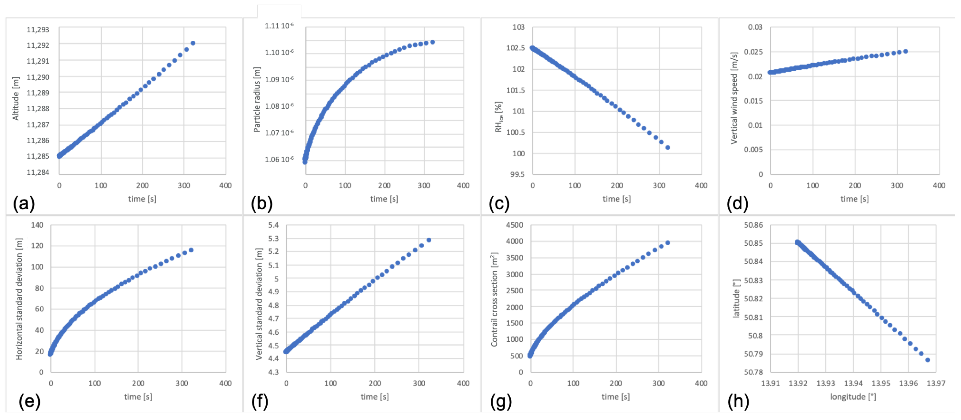
The approach described in Section 2 was applied to 13 flights generating a contrail. Figure 8 and Figure 9 provide an example contrail induced during a flight from Manchester Intl Airport, United Kingdom (EGCC) to Paphos International Airport, Cyprus (LCPH). On the 26 September 2018 at 3 p.m., above Děčín, the A320 aircraft had an altitude of 37,000 ft, according to the photographic and ADS-B identification. SOPHIA modeled the whole flight and calculated the input variables proving the contrail formation with the Schmidt–Appleman criterion above Děčín (i.e., a fuel flow of m ˙ f = 0.584 k g s 1 and a v T A S =   227.36 m s 1 ). The high amount of measured ice-supersaturation at FL 370 (Figure 8, left) holds a good potential for contrail formation during the major part of the cruise flight (red line in Figure 8, left and Figure 9). Relatively low modeled horizontal wind speed at FL 370 (Figure 8, right) above Prague did not drift the contrail out of the camera window. For this reason, the camera observed a contrail lifetime of five min and 42 s (see, also, Table 2 for details).
Additionally, the modeled profile from EGCC to LCPH with modeled weather data from 26 September 2018, 12 p.m. with 3 h forecast with a cruising altitude of 37,000 ft indicates contrail formation for the majority of the cruise phase (Figure 9).
From the modeled vertical velocity, we estimated a weak turbulent environment with ε = 0.057 m 2 s 3 . Subsequently, the modeled relative humidity was replaced with the radiosonde measurement at station T3930163 from 26 September 2018, 12 p.m. and the contrail life cycle was calculated according to the methodology described in Section 3. We modeled a contrail lifetime of five min and 23 s.
Moderate positive (upward) vertical wind speeds (Figure 10d) result in an upward shift in the contrail during the entire lifetime (Figure 10a). The contrail died due to an undersaturated atmosphere, i.e., r H ice < 100 % (Figure 10c). During the entire lifetime, the mean particle radius grows logarithmically (Figure 10b), an often observed behavior [66]. The horizontal wind coming from north-west (Figure 8, right) drifts the contrail towards south-east (Figure 10h).
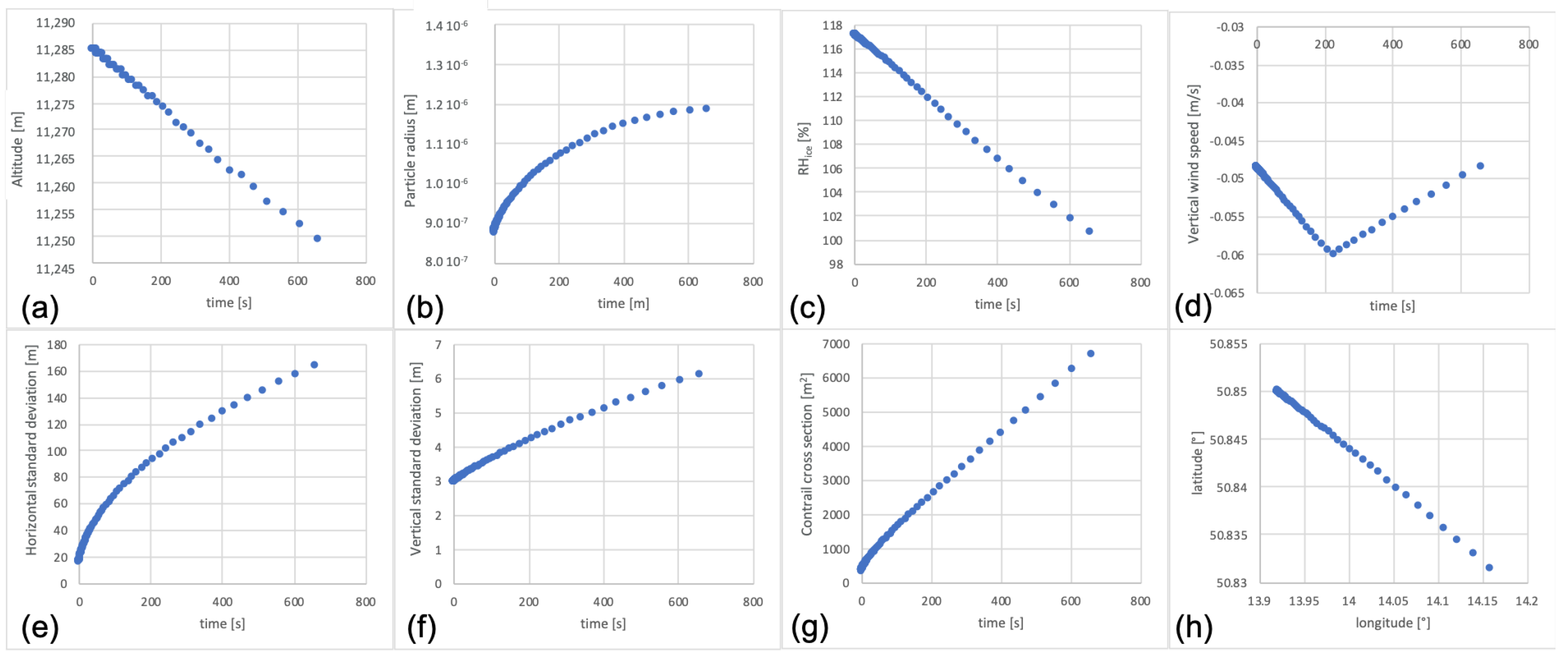
Another single contrail formed by flight 471F5D on the 16 September at 2 p.m. in a stronger turbulent environment ( ε = 0.0098 m 2 s 3 ) is shown in Figure 11. Again, the contrail was induced by an A320 aircraft from Eindhoven Airport, Nederlands (EHEH) to Belgrade Nikola Tesla Airport, Serbia (LYBE). Despite a strong turbulent environment, the contrail was observed by the camera for twelve min and 19 s (see, also, Table 2). In this case, the contrail lifetime is impacted by a negative (downward) vertical wind (Figure 11d) moving the contrail out of the ice-supersaturated region (Figure 11c). The presence of a highly turbulent environment leads to an accelerated increase in the average particle diameter (as depicted in Figure 11b) and contrail dimensions (as depicted in Figure 11e,f), in comparison to the contrail illustrated in Figure 10.
Both single contrail examples show the diversity of the influencing variables in the contrail life-cycle model. Besides the high sensitivity of the relative humidity, the direction of the vertical wind is decisive for the contrail life cycle. The atmospheric turbulence, on the other hand, significantly influences the growth in the contrail and its ice particles.
Table 2 additionally summarizes thirteen observed and modeled contrails above Děčín between the 4 and 26 September 2018, which could be modeled realistically after replacing modeled humidity values with measured data. The difference between observed and calculated lifetime is within a range of 10%. Usually, we slightly underestimate the lifetime of our model.
Note, single contrails are usually observed in weak ice-saturated atmospheres corresponding to a short contrail lifetime. In strong ice-supersaturated areas, natural clouds and/or additional contrails may complicate the identification of individual contrails with one of the cameras. Furthermore, modeling individual contrails in the presence of neighbored natural or artificial clouds requires modeling the distribution of competitive resources, such as condensation nuclei and humidity among all clouds. These phenomena are under investigation. However, for validation purposes, the visual contrail identification is somehow restricted to contrails in a low-cloud atmosphere (for automatically distinguishing the contrail from natural clouds) and to low horizontal wind conditions (for the contrail not moving out of the camera window).

4.3. Comparison with Other Studies

The results of our modeled contrails can not only be compared with photographic measurements but also with in-situ measurements. Despite lots of technical problems [67], contrails have been observed since 1972 [68]. The contrail microphysical properties modeled in this study are in the same order of magnitude as measurements of young contrails by [69,70], whereas [16,71] measured the transition of (old) contrails into cirrus clouds yielding larger dimensions (up to 10.000   m ), larger particle radii (up to 10 μ m ) and longer lifetimes (up to 1000 s ).
Additionally, the modeled contrails can be compared with remote-sensing observations which have been performed since 1975 [72]. The dimensions and lifetimes of the modeled contrails are in the same order of magnitude as observed by [10,20,73,74]. Observations of long-living contrails, on the contrary, result in longer life times [75].
Furthermore, there are Large Eddy Simulations of contrails [76] with a coarse resolution in time and space, but with results in the same order of magnitude as the current model.

5. Conclusions and Outlook

In this study, we developed a method for validating a contrail life-cycle model with ground-based camera observations, globally modeled weather data, and locally measured humidity values. After identifying the contrail-inducing aircraft and observing the contrail lifetime, we model the flight with an aircraft flight performance model SOPHIA and estimate the aircraft state parameters (such as thrust, TAS and fuel flow) above Děčín with an impact on the conditions of contrail formation and the initial state of the contrail. Subsequently, we model the whole contrail life cycle and compare the calculated lifetime with the observed lifetime. We met the observed lifetime with an accuracy of 90%. On average, we slightly underestimated the lifetime. The accuracy might be limited because, during the probing, the radiosonde may be laterally drifted by wind. In this case, the radiosonde would measure the humidity in the vicinity of the contrail.
The contrail lifetime strongly depends on two atmospheric criteria. First, the amount and vertical depth of ice supersaturation r H ice and second, the direction of the vertical wind speed. Therewith, we derive the following possible reasons for the short lifetime due to r H ice < 100 % : In the presence of a small vertical thickness of the ice-supersaturated layer and a strong downward vertical wind, the contrail will quickly die. With less significance, we found that low cruise altitudes and low fuel burn lead to a lower number of particles, as this is initially proportional to the number of soot particles emitted. However, these few ice particles are larger because they share the same amount of humidity. Those large ice particles descend faster and, therefore, reduce the contrail lifetime.
On the other hand, in the presence of a small amount of ice-supersaturation, the contrail dies due to an I W C < 10 8 kg m 3 , because the humidity is distributed in a large contrail volume. In the presence of weak vertical wind, the contrail cannot catch enough surrounding humidity. This results in a larger number of (small) ice particles. This effect can be supported by high cruising speeds with high fuel flow and a large number of emitted soot particles.
Finally, the contrail vertical movement
d z d t = f ( v z , r p )
depends on the vertical wind speed v z and is counteracted by the ice-particle sedimentation speed v s , p as a function of the ice particle radius r p . From this follows, for the contrail lifetime, L T contrail
L T contrail r H ice d z d t .
Besides theoretical considerations on the contrail lifetime, from this study, many ideas emerged to continue this research. From the again-demonstrated uncertainty in the humidity data of global weather models, the idea arises to develop humidity’s own weather data set from a network of radiosonde measurements and/or IAGOS data sets for the contrail life-cycle model and for trajectory optimizations (such as TOMATO [35,77]), following the ideas of Sun et al. [78]. A higher local resolution of weather data would further improve the estimation of the sheared component of the standard-deviation matrix.
The developed approach could also be applied to ice-supersaturated and cold atmospheres (identified by radiosonde measurements) in which contrail formation and contrail life cycles have been modeled/predicted, but not observed. In this case, the range of lifetimes would be interesting.
Now that the contrail life-cycle model has been validated, the contrail optical properties model [79] will be linked to the camera observations and aircraft pairings [21] in the future. With the help of machine learning, correlations between location, altitude, aircraft type, atmospheric properties, and the radiative forcing of the contrails can be determined.

Author Contributions

Conceptualization, J.R.; methodology, S.L., J.H. and J.R.; software, S.L. and J.R.; validation, S.L. and J.R.; formal analysis, S.L. and J.R.; investigation, S.L. and J.R.; resources, S.L., J.H., H.F. and J.R.; data curation, S.L., J.H. and J.R.; writing—original draft preparation, J.R.; writing—review and editing, S.L., J.H., H.F. and J.R.; visualization, J.R.; supervision, J.R.; project administration, J.R.; funding acquisition, J.R. All authors have read and agreed to the published version of the manuscript.

Funding

This research was funded by EUROCONTROL via contract NO.19-220468-C. Its contents are solely the authors’ responsibility and do not necessarily represent the official views of EUROCONTROL. Furthermore, this research was funded by Czech Technical University in Prague institutional support and grant number SGS19/129/OHK2/2T/16.

Data Availability Statement

Not applicable.

Acknowledgments

The authors would like to thank Stanley Förster, Thomas Zeh, and Marco Berger for programming support.

Conflicts of Interest

The authors declare no conflict of interest.

References

  1. Lee, D.S.; Pitari, G.; Grewe, V.; Gierens, K.; Penner, J.E.; Petzold, A.; Prather, M.J.; Schumann, U.; Bais, A.; Berntsen, T.; et al. Transport impacts on atmosphere and climate: Aviation. Atmos. Environ. 2010, 44, 4678–4734. [Google Scholar] [CrossRef] [PubMed]
  2. Lee, D.; Fahey, D.; Skowron, A.; Allen, M.; Burkhardt, U.; Chen, Q.; Doherty, S.; Freeman, S.; Forster, P.; Fuglestvedt, J.; et al. The contribution of global aviation to anthropogenic climate forcing for 2000 to 2018. Atmos. Environ. 2021, 244, 117834. [Google Scholar] [CrossRef] [PubMed]
  3. Burkhardt, U.; Kärcher, B.; Mannstein, H.; Schumann, U. Climate impact of contrails and contrail cirrus. In Subject Specific White Paper IV, Aviation Climate Change Research Initiative (ACCRI); United States Department of Transportation, Federal Aviation Administration: Washington, DC, USA, 2008. [Google Scholar]
  4. Rosenow, J.; Chen, G.; Fricke, H.; Wang, Y. Factors Impacting Chinese and European Vertical Fight Efficiency. Aerospace 2022, 9, 76. [Google Scholar] [CrossRef]
  5. Gierens, K.; Vázquez-Navarro, M. Statistical analysis of contrail lifetimes from a satellite perspective. Meteorol. Z. 2018, 27, 183–193. [Google Scholar] [CrossRef]
  6. Rosenow, J. Optical Properties of Condenstation Trails. Ph.D. Thesis, Technische Universität Dresden, Dresden, Germany, 2016. [Google Scholar]
  7. Vázquez-Navarro, M.; Mannstein, H.; Mayer, B. An automatic contrail tracking algorithm. Atmos. Meas. Tech. 2010, 3, 1089–1101. [Google Scholar] [CrossRef]
  8. Mannstein, H.; Vázquez-Navarro, M.; Graf, K.; Duda, D.; Schumann, U. Contrail Detection in Satellite Images. In Atmospheric Physics: Background—Methods—Trends; Springer: New York, NY, USA, 2012; p. 433. [Google Scholar]
  9. Zhang, G.; Zhang, J.; Shang, J. Contrail Recognition with Convolutional Neural Network and Contrail Parameterizations Evaluation. SOLA 2018, 14, 132–137. [Google Scholar] [CrossRef]
  10. Duda, D.P.; Bedka, S.T.; Minnis, P.; Spangenberg, D.; Khlopenkov, K.; Chee, T.; Smith, W.L., Jr. Northern Hemisphere contrail properties derived from Terra and Aqua MODIS data for 2006 and 2012. Atmos. Chem. Phys. 2019, 19, 5313–5330. [Google Scholar] [CrossRef]
  11. McCloskey, K.; Geraedts, S.; Van Arsdale, C.; Brand, E. A human-labeled Landsat-8 contrails dataset. In Proceedings of the ICML 2021 Workshop on Tackling Climate Change with Machine Learning, Virtually, 23 July 2021. [Google Scholar]
  12. Meijer, V.R.; Kulik, L.; Eastham, S.D.; Allroggen, F.; Speth, R.L.; Karaman, S.; Barrett, S.R.H. Contrail coverage over the United States before and during the COVID-19 pandemic. Environ. Res. Lett. 2022, 17, 034039. [Google Scholar] [CrossRef]
  13. Wang, Z.; Bugliaro, L.; Jurkat-Witschas, T.; Heller, R.; Burkhardt, U.; Ziereis, H.; Dekoutsidis, G.; Wirth, M.; Groß, S.; Kirschler, S.; et al. Observations of microphysical properties and radiative effects of contrail cirrus and natural cirrus over the North Atlantic. Atmos. Chem. Phys. Discuss. 2022, 2022, 1–36. [Google Scholar] [CrossRef]
  14. Schumann, U. A contrail cirrus prediction tool. In Proceedings of the International Conferences on Transport, Atmosphere and Climate, DLR/EUR, Aachen and Maastricht, Prien am Chiemsee, Germany, 22–25 June 2009. [Google Scholar]
  15. Schumann, U.; Heymsfield, A. On the lifecycle of individual contrails and contrail cirrus. AMS Meteorol. Monogr. 2017, 58, 3.1–3.24. [Google Scholar]
  16. Jones, H.M.; Haywood, J.; Marenco, F.; O’Sullivan, D.; Meyer, J.; Thorpe, R.; Gallagher, M.W.; Krämer, M.; Bower, K.N.; Rädel, G.; et al. A methodology for in-situ and remote sensing of microphysical and radiative properties of contrails as they evolve into cirrus. Atmos. Chem. Phys. 2012, 12, 8157–8175. [Google Scholar] [CrossRef]
  17. Spinhirne, J.; Hart, W.; Duda, D. Evolution of the morphology and microphysics of contrail cirrus from airborne remote sensing. Geophys. Res. Lett. 1998, 25, 1153–1156. [Google Scholar] [CrossRef]
  18. Rap, A.; Forster, P.M.; Haywood, J.M.; Jones, A.; Boucher, O. Estimating the climate impact of linear contrails using the UK Met Office climate model. Geophys. Res. Lett. 2010, 37, 1–6. [Google Scholar] [CrossRef]
  19. Schmidt, E. Die Entstehung von Eisnebel aus den Auspuffgasen von Flugmotoren. Schriften Dtsch. Akad. Luftfahrtforsch. Verl. Oldenbourg MÜNchen/Berlin 1941, 44, 1–15. [Google Scholar]
  20. Sussmann, R.; Gierens, K.M. Lidar and numerical studies on the different evolution of vortex pair and secondary wake in young contrails. J. Geophys. Res. 1999, 104, 2131–2142. [Google Scholar] [CrossRef]
  21. Lán, S.; Hospodka, J. Contrail Lifetime in Context of Used Flight Levels. Sustainability 2022, 14, 5877. [Google Scholar] [CrossRef]
  22. Hoff, A.M. Humidity Measurements by Aircraft of the E-AMDAR Fleet; Observing Networks and Data: Offenbach am Main, Germany, 2008. [Google Scholar]
  23. World Meteorological Organization. Aircraft Meteorological Data Relay (AMDAR) Reference Manual; WMO No. 958; Secretariat of the World Meteorological Organization: Geneva, Switzerland, 2003. [Google Scholar]
  24. Rosenow, J.; Lindner, M.; Scheiderer, J. Advanced Flight Planning and the Benefit of In-Flight Aircraft Trajectory Optimization. Sustainability 2021, 13, 1383. [Google Scholar] [CrossRef]
  25. Zhang, Y.; Sun, K.; Gao, Z.; Pan, Z.; Shook, M.; Li, D. Diurnal Climatology of Planetary Boundary Layer Height Over the Contiguous United States Derived From AMDAR and Reanalysis Data. J. Geophys. Res. Atmos. 2020, 125, e2020JD032803. [Google Scholar] [CrossRef]
  26. NOAA/Earth System Research Laboratory (ESRL). Aircraft Meteorological Data Reports (AMDAR) and Aircraft Communications Addressing and Reporting System (ACARS) Data; Version 1.0; UCAR/NCAR—Earth Observing Laboratory: Boulder, CO, USA, 2023. [Google Scholar]
  27. Hoff, A.; Smit, H.; Taylor, S.; Carlberg, S.; Berechree, M. Advancements in the AMDAR Humidity Sensing 2023. In Proceedings of the WMO Technical Conference on Meteorological and Environmental Instruments and Methods of Observation (TECO-2010), Helsinki, Finland, 30 August–1 September 2010. [Google Scholar]
  28. Petzold, A.; Thouret, V.; Gerbig, C.; Zahn, A.; Brenninkmeijer, C.; Gallagher, M.; Hermann, M.; Pontaud, M.; Ziereis, H.; Boulanger, D.; et al. Global-scale atmosphere monitoring by in-service aircraft—Current achievements and future prospects of the European Research Infrastructure IAGOS. Tellus B 2015, 67, 28452. [Google Scholar] [CrossRef]
  29. Reutter, P.; Neis, P.; Rohs, S.; Sauvage, B. Ice supersaturated regions: Properties and validation of ERA-Interim reanalysis with IAGOS in situ water vapour measurements. Atmos. Chem. Phys. 2020, 20, 787–804. [Google Scholar] [CrossRef]
  30. Oolman, L. University of Wyoming, Atmospheric Soundings. 2023. Available online: https://weather.uwyo.edu/upperair/sounding.html (accessed on 2 May 2023).
  31. Govett, M. NOAA/ESRL Radiosonde Database; Global Systems Laboratory: Boulder, CO, USA, 2023. [Google Scholar]
  32. Vaisala Radiosonde RS41-SG; Datasheet. 2017. Available online: https://www.vaisala.com/sites/default/files/documents/WEA-MET-RS41-Datasheet-B211321EN.pdf (accessed on 2 May 2023).
  33. National Oceanic and Atmospheric Administration. Global Data Assimilation System (GDAS), Technical Report. 2016. Available online: http://ready.arl.noaa.gov/gdas1.php (accessed on 2 May 2023).
  34. Lindner, M.; Rosenow, J.; Zeh, T.; Fricke, H. In-Flight Aircraft Trajectory Optimization within Corridors Defined by Ensemble Weather Forecasts. Aerospace 2020, 7, 144. [Google Scholar] [CrossRef]
  35. Förster, S.; Rosenow, J.; Lindner, M.; Fricke, H. A Toolchain for Optimizing Trajectories under real Weather Conditions and Realistic Flight Performance. In Proceedings of the Greener Aviation, Brussels, Belgium, 11–13 October 2016. [Google Scholar]
  36. Rosenow, J.; Zeh, T.; Lindner, M.; Förster, S.; Fricke, H.; Caraud, A. Multiple Aircraft in a multi-criteria Trajectory Optimization. In Proceedings of the Fifteenth USA/Europe Air Traffic Management Research and Development Seminar (ATM2023), Savannah, GA, USA, 5–9 June 2023. [Google Scholar]
  37. Brent, R.P. An algorithm with guaranteed convergence for finding a zero of a function. Comput. J. 1971, 14, 422–425. [Google Scholar] [CrossRef]
  38. Sun, J.; Hoekstra, J.M.; Ellerbroek, J. OpenAP: An Open-Source Aircraft Performance Model for Air Transportation Studies and Simulations. Aerospace 2020, 7, 104. [Google Scholar] [CrossRef]
  39. Rosenow, J.; Förster, S.; Lindner, M.; Fricke, H. Multi-objective trajectory optimization. In International Transportation; Special Edition 1; Trialog Publishers Verlagsgesellschaft: Baiersbronn, Germany, 2016. [Google Scholar]
  40. Sonntag, D. Advancements in Field Hygrometry, Review Article. Meteorol. Z. 1994, 3, 51–66. [Google Scholar] [CrossRef]
  41. Schumann, U. On conditions for Contrail formation from aircraft exhaust. Meteorol. Z. 1996, 5, 4–23. [Google Scholar] [CrossRef]
  42. Paugam, R.; Paoli, R.; Cariolle, D. Influence of vortex dynamics and atmospheric turbulence on the early evolution of a contrail. Atmos. Chem. Phys. 2010, 10, 3933–3952. [Google Scholar] [CrossRef]
  43. Holzäpfel, F. Probabilistic Two-Phase Wake Vortex Decay and Transport Model. J. Aircr. 2003, 40, 323–331. [Google Scholar] [CrossRef]
  44. Foken, T. Angewandte Meteorologie; Springer: Berlin/Heidelberg, Germany, 2006. [Google Scholar]
  45. Sharman, R.D.; Cornman, L.B.; Meymaris, G.; Pearson, J. Description and Derived Climatologies of Automated In Situ Eddy-Dissipation-Rate Reports of Atmospheric Turbulence. J. Appl. Meteorol. Climatol. 2014, 53, 1416–1432. [Google Scholar] [CrossRef]
  46. Sharman, R.D.; Pearson, J.M. Prediction of Energy Dissipation Rates for Aviation Turbulence. Part I: Forecasting Nonconvective Turbulence. J. Appl. Meteorol. Climatol. 2017, 56, 317–337. [Google Scholar] [CrossRef]
  47. Etling, D. Theoretische Meteorologie; Springer: Berlin/Heidelberg, Germany, 2008. [Google Scholar]
  48. Betz, A. Verhalten von Wirbelsystemen. Z. Für Angew. Math. Und Mech. 1932, 12, 164–174. [Google Scholar] [CrossRef]
  49. Glauert, H. Die Grundlagen der Tragflügel- und Luftschraubentheorie, 1st ed.; Softcover Reprint of the Original 1929 ed.; Springer: New York, NY, USA, 2013. [Google Scholar]
  50. Sussmann, R.; Gierens, K.M. Differences in early contrail evolution of two-engine versus four-engine aircraft: Lidar measurements and numerical simulations. J. Geophys. Res. 2001, 106, 4899–4911. [Google Scholar] [CrossRef]
  51. Anderson, J.D. Introduction to Flight; McGraw-Hill: New York, NY, USA, 1989. [Google Scholar]
  52. Sarpkaya, T. A new model for vortex decay in the atmosphere. J. Aircr. 2000, 37, 53–61. [Google Scholar] [CrossRef]
  53. Burnham, D.C.; Hallock, J.N. Chicago Monostatic Acoustic Vortex Sensor System; Report No. DOT-TSC-FAA-79-103.IV; Federal Aviation Administration (FAA): Washington, DC, USA, 1982. [Google Scholar]
  54. Holzäpfel, F.; Gerz, T.; Baumann, R. The turbulent decay of trailing vortex pairs in stably stratified environments. Aerosp. Sci. Technol. 2001, 5, 95–108. [Google Scholar] [CrossRef]
  55. Schumann, U.; Konopka, P.; Baumann, R.; Busen, R.; Gerz, T.; Schlager, D.; Schulte, P.; Volkert, H. Estimate of diffusion parameters of aircraft exhaust plumes near the tropopause from nitric oxide and turbulence measurements. J. Geophys. Res. 1995, 100, 14147–14162. [Google Scholar] [CrossRef]
  56. Merziger, G.; Mühlbach, G.; Wille, D.; Wirth, T. Formeln + Hilfen zur Höheren Mathematik; Binomi: Hannover, Germany, 2001. [Google Scholar]
  57. Rosenow, J.; Kaiser, M.; Fricke, H. Modeling Contrail life cycles based on highly precise flight profile data of modern aircraft. In Proceedings of the International Conference on Research in Airport Transportation (ICRAT), Berkeley, CA, USA, 22–25 May 2012. [Google Scholar]
  58. Rosenow, J.; Fricke, H. Individual Condensation Trails in Aircraft Trajectory Optimization. Sustainability 2019, 11, 6082. [Google Scholar] [CrossRef]
  59. Döplheuer, A.; Lecht, M. Influence of Engine Performance on Emission Characteristic; RTO MP-14; Canada Communication Group. Inc.: Lisabon, Portugal, 1998. [Google Scholar]
  60. Schumann, U.; Ström, J.; Busen, R.; Baumann, R.; Gierens, K.; Krautschunk, M.; Schröder, F.P.; Stringl, J. In situ observations of particles in jet aircraft exhausts and contrails for different sulfur containing fuels. J. Geophys. Res. 1996, 101, 6853–6869. [Google Scholar] [CrossRef]
  61. Myhre, G.; Shindell, D.; Bréon, F.M.; Collins, W.; Fuglestvedt, J.; Huang, J.; Koch, D.; Lamarque, J.F.; Lee, D.; Mendoza, B.; et al. Anthropogenic and Natural Radiative Forcing. In Climate Change 2013: The Physical Science Basis. Contribution of Working Group I to the Fifth Assessment Report of the Intergovernmental Panel on Climate Change; Cambridge University Press: Cambridge, UK, 2013. [Google Scholar]
  62. Kraus, H. Die Atmosphäre der Erde; Springer: Berlin/Heidelberg, Germany, 2001. [Google Scholar]
  63. Stokes, G.G. On the effect of internal friction of fluids on the motion of pendulums. Trans. Camb. Philos. Soc. 1851, 9, 1–10. [Google Scholar]
  64. Roedel, W. Physik Unserer Umwelt, Die Atmosphäre; Springer: Berlin/Heidelberg, Germany, 2000. [Google Scholar]
  65. Sutherland, W. The viscosity of gases and molecular force. Philos. Mag. 1893, 5, 507–531. [Google Scholar] [CrossRef]
  66. Pfitzenmaier, L. Studying ice particle growth processes in mixed-phase clouds using spectral polarimetric radar measurements. Ph.D. Thesis, Technische Universität Delft, Delft, The Netherlands, 2018. [Google Scholar]
  67. Heymsfield, A.; Baumgardner, D.; DeMott, P.; Forster, P.; Gierens, K. Contrail microphysics. Bull. Am. Meteorol. Soc. 2010, 91, 456–472. [Google Scholar] [CrossRef]
  68. Knollenberg, R.G. Measurements of the Growth of the Ice Budget in a Persisting Contrail. J. Atmos. Sci. 1972, 29, 1367–1374. [Google Scholar] [CrossRef]
  69. Poellot, M.R.; Arnott, W.P.; Hallett, J. In situ observations of contrail microphysics and implications for their radiative impact. J. Geophys. Res. Atmos. 1999, 104, 12077–12084. [Google Scholar] [CrossRef]
  70. Kaufmann, S.; Voigt, C.; Jeßberger, P.; Jurkat, T.; Schlager, H.; Schwarzenboeck, A.; Klingebiel, M.; Thornberry, T. In-situ measurements of ice saturation in young contrails. Geophys. Res. Lett. 2014, 41, 702–709. [Google Scholar] [CrossRef]
  71. Schröder, F.; Kärcher, B.; Duroure, C.; Ström, J.; Petzold, A.; Gayet, J.-F.; Strauss, B.; Wendling, P.; Borrmann, S. On the Transition of Contrails into Cirrus Clouds. J. Atmos. Sci. 2000, 57, 464–480. [Google Scholar] [CrossRef]
  72. Hoshizaki, H.; Anderson, L.B.; Conti, R.J.; Farlow, N.; Meyer, J.W.; Overcamp, T.; Redler, K.O.; Watson, V. Aircraft wake microscale phenomena. In The Stratosphere Perturbed by Propulsion Effluents; Climatic Impact Assessment Program; Grobecker, A.J., Ed.; Department of Transportation: Fort Belvoir, VA, USA, 1975; pp. 2-1–2-79. [Google Scholar]
  73. Baumann, R.; Busen, R.; Fimpel, H.P.; Kiemle, C.; Reinhardt, M.; Quante, M. Measurements on contrails of commercial aircraft. In Proceedings of the 8th Symposium on Meteorological Observations and Instrumentation, Anaheim, CA, USA, 17–22 January 1993; pp. 484–489. [Google Scholar]
  74. Minnis, P.; Young, D.F.; Garber, D.P.; Nguyen, L.; Smith, W.L., Jr.; Palikonda, R. Transformation of contrails into cirrus during SUCCESS. Geophys. Res. Lett. 1998, 25, 1157–1160. [Google Scholar] [CrossRef]
  75. Atlas, D.; Wang, Z.; Duda, D. Contrails to Cirrus—Morphology, Microphysics, and Radiative Properties. J. Appl. Meteorol. Climatol. 2006, 45, 5–19. [Google Scholar] [CrossRef]
  76. Chlond, A. Large-Eddy Simulation of Contrails. J. Atmos. Sci. 1997, 55, 796–819. [Google Scholar] [CrossRef]
  77. Rosenow, J.; Fricke, H.; Sherry, L. Time of the day-dependent impact of Contrail Avoidance Strategies on Airline Delay Costs. In Proceedings of the Fifteenth USA/Europe Air Traffic Management Research and Development Seminar (ATM2023), Savannah, GA, USA, 5–9 June 2023. [Google Scholar]
  78. Sun, J.; Vû, H.; Ellerbroek, J.; Hoekstra, J.M. Weather field reconstruction using aircraft surveillance data and a novel meteo-particle model. PLoS ONE 2018, 13, e0205029. [Google Scholar] [CrossRef]
  79. Rosenow, J.; Fricke, H. When do contrails cool the atmosphere? In Proceedings of the SESAR Innovation Days (SID 2022), Budapest, Hungary, 5–8 December 2022.
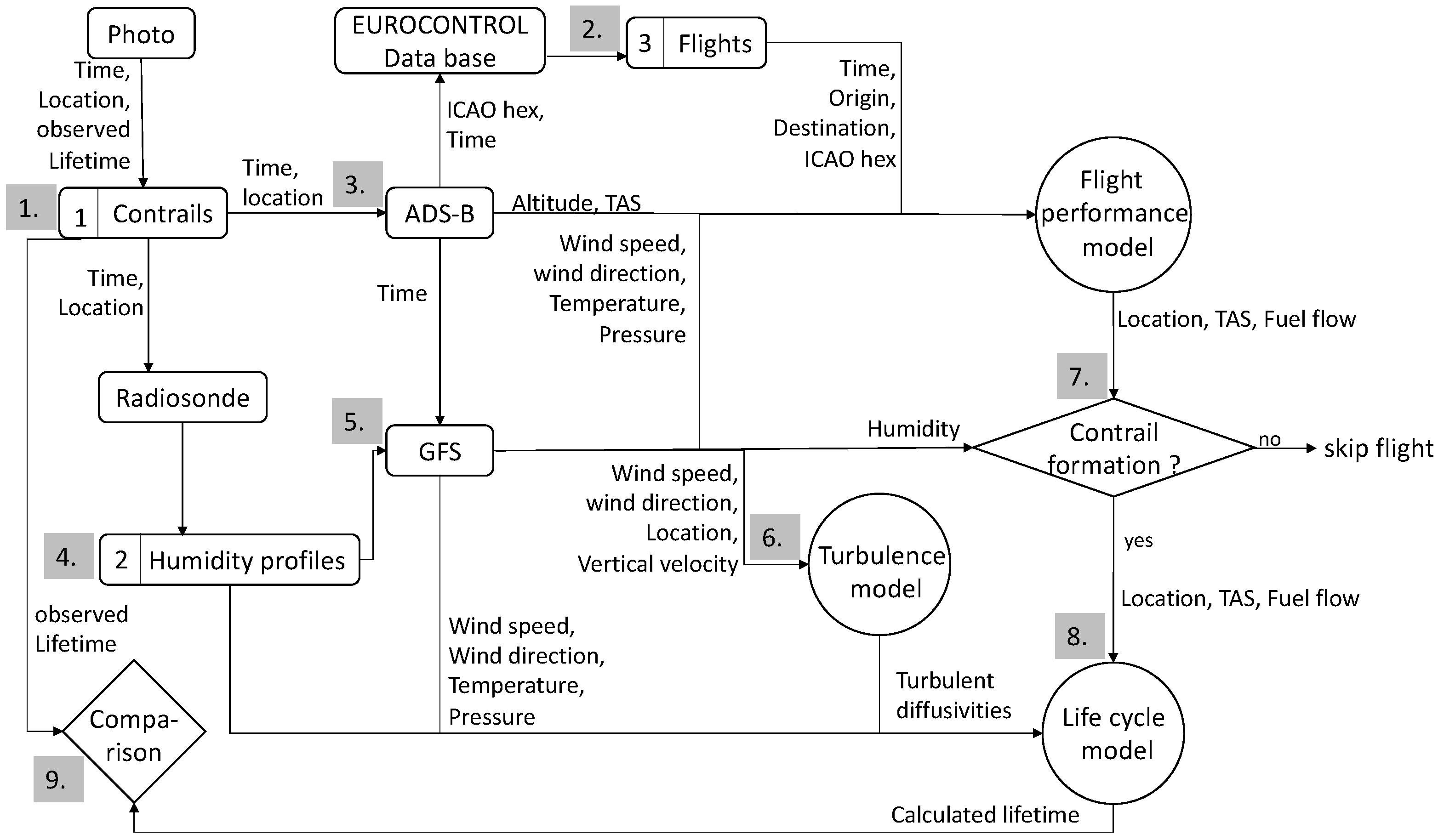
Figure 1. Methodological approach for the validation of the contrail life-cycle model using automatic ground-based contrail detection, ADS-B flight data, radiosonde measurements, and modeled weather data.
Sustainability 15 08669 g001
Figure 2. Relative humidity profiles on 26th of September, 2019, 6 p.m. above Prague. Left: modeled by Global Forecast System (GFS) at 51 North, 14 East. Since the model output is restricted to layers every 50 hPa, the modeled data is interpolated for desired altitudes. Right: measured by a radiosonde. Although persistent contrails were detected in Prague at 6 p.m. at flight level 200, the modeled humidity profile does not indicate the ice supersaturation, which was measured with the radiosonde. For this reason, the radiosonde measurement seems more realistic.
Sustainability 15 08669 g002
Figure 3. Tangential velocity v t ( r ) as function of radius r within a vortex. The vortex radius r is defined, where v t ( r ) is ( e ) 1 times the maximum value v t ( r c ) .
Sustainability 15 08669 g003
Figure 4. Initial vertical contrail dimension depending on wake vortex characteristics [43] fall down time t and descent speed v s for a single wake vortex.
Sustainability 15 08669 g004
Figure 5. Contrail horizontal extension c h at the end of the dissipation regime depending on initial horizontal vortex spacing b 0 and vortex radius r.
Sustainability 15 08669 g005
Figure 6. Model of a two-dimensional Gaussian plume. The flight path is considered along with time on the x-axis. The older state of the contrail is, therefore, represented by pale-orange ellipses.
Sustainability 15 08669 g006
Figure 7. Impact of the vertical wind speed v z on particle radius r p and contrail lifetime in a mean turbulent environment ( ε = 5 × 10 5   m 2 s 3 ). In strong vertical upward winds, the contrail remains in the ice-supersaturated region with increasing lifetime.
Sustainability 15 08669 g007
Figure 8. Modeled flight path 40756A from EGCC to LCPH on 26 September 2018 at 3 p.m. The black dot shows the position of the radiosonde station Prague (50°5.28 N; 14°25.248 E) which is 80 km to the southeast of Děčín, where the camera is located. The red line indicates flight segments with contrail formation.
Sustainability 15 08669 g008
Figure 9. Modeled flight profile 40756A from EGCC to LCPH on 26 September 2018 at 5 p.m. with a cruising altitude of 37,000 ft above Děčín (black vertical line), where the ice-supersaturated region (blue dots) has at least a vertical depth of 130 m. The red line indicates flight segments with contrail formation.
Sustainability 15 08669 g009
Figure 10. (ah) Modeled contrail life cycle of flight 40756A from EGCC to LCPH on 26 September 2018 at 3 p.m. In this case, a weak turbulent environment with ε = 0.057 m 2 s 3 was estimated.
Sustainability 15 08669 g010
Figure 11. (ah) Modeled contrail life cycle of flight 471F5D from EHEH to LYBE on 16 September 2018 at 1 p.m. in a stronger turbulent environment with ε = 0.0098 m 2 s 3 .
Sustainability 15 08669 g011
Table 1. Assumed linear correlation between eddy dissipation rate ε and horizontal diffusivity D h . Values are taken from measurements by Schumann et al. [55].
Eddy Dissipation RateHorizontal Diffusivity
ε [m 2 s 3 ] D h [m 2 s 2 ]
1 × 10 6 5.00
5 × 10 6 8.75
1 × 10 5 12.50
5 × 10 5 16.254
1 × 10 4 20.00
Table 2. Modeled flights and contrail lifetimes and comparison with observed lifetimes.
ICAOAltitudeDepart.Dest. m ˙ f v TAS Obs.Calc.
Hex[ft] [kg/s][m/s]LifetimeLifetime
44017637,000LHBPEHAM0.588227.0500:05:4300:05:53
40756A37,000LOWWEGPH0.592226.9500:10:2500:10:48
471F7E37,000EGGWLRCL0.590229.8700:11:5200:11:27
4B990236,975EGCNLTAI0.586228.2700:05:5500:05:03
40667435,000LOWWEGLL0.676235.0500:05:0500:05:14
4BB84339,000EHAMLTFJ0.580227.6900:05:1300:05:13
40097C36,975EGLLLOWW0.581226.3300:10:2900:09:38
471F5D37,025EHEHLYBE0.604230.4500:12:1900:10:59
3C097B28,450EDDPLTAI0.888212.9600:13:4600:12:52
45CABA34,975EKBILGPZ0.551229.4200:10:1700:09:59
40756A37,000EGCCLCPH0.584227.3600:05:4200:05:23
Disclaimer/Publisher’s Note: The statements, opinions and data contained in all publications are solely those of the individual author(s) and contributor(s) and not of MDPI and/or the editor(s). MDPI and/or the editor(s) disclaim responsibility for any injury to people or property resulting from any ideas, methods, instructions or products referred to in the content.