
Review of Power Control Methods for a Variable Average Power Load Model Designed for a Microgrid with Non-Controllable Renewable Energy Sources

Abstract
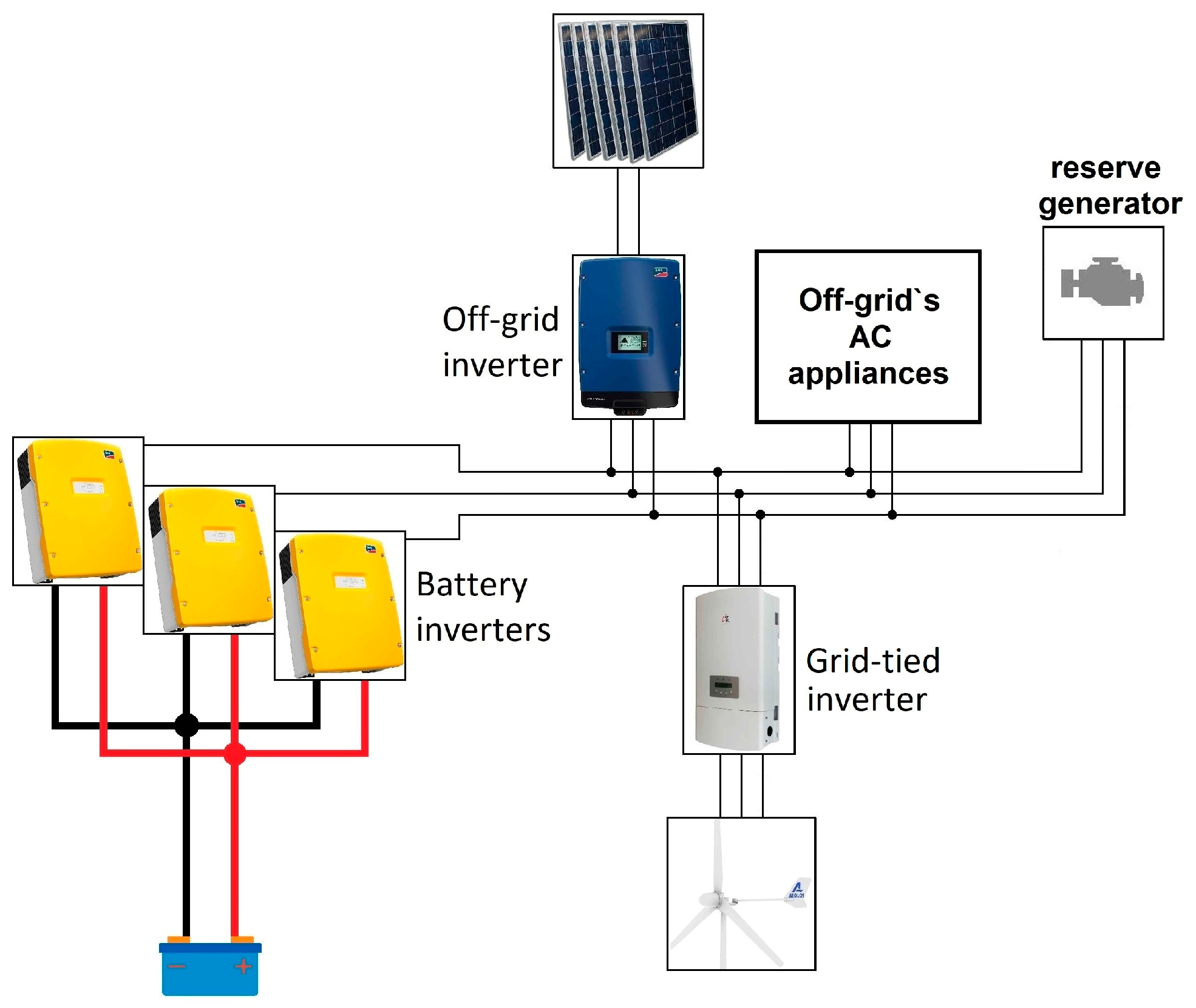
:1. Introduction
2. Average Power Control Methods
2.1. Burst Average Power Control Method
2.2. Phase Delay Average Power Control Method
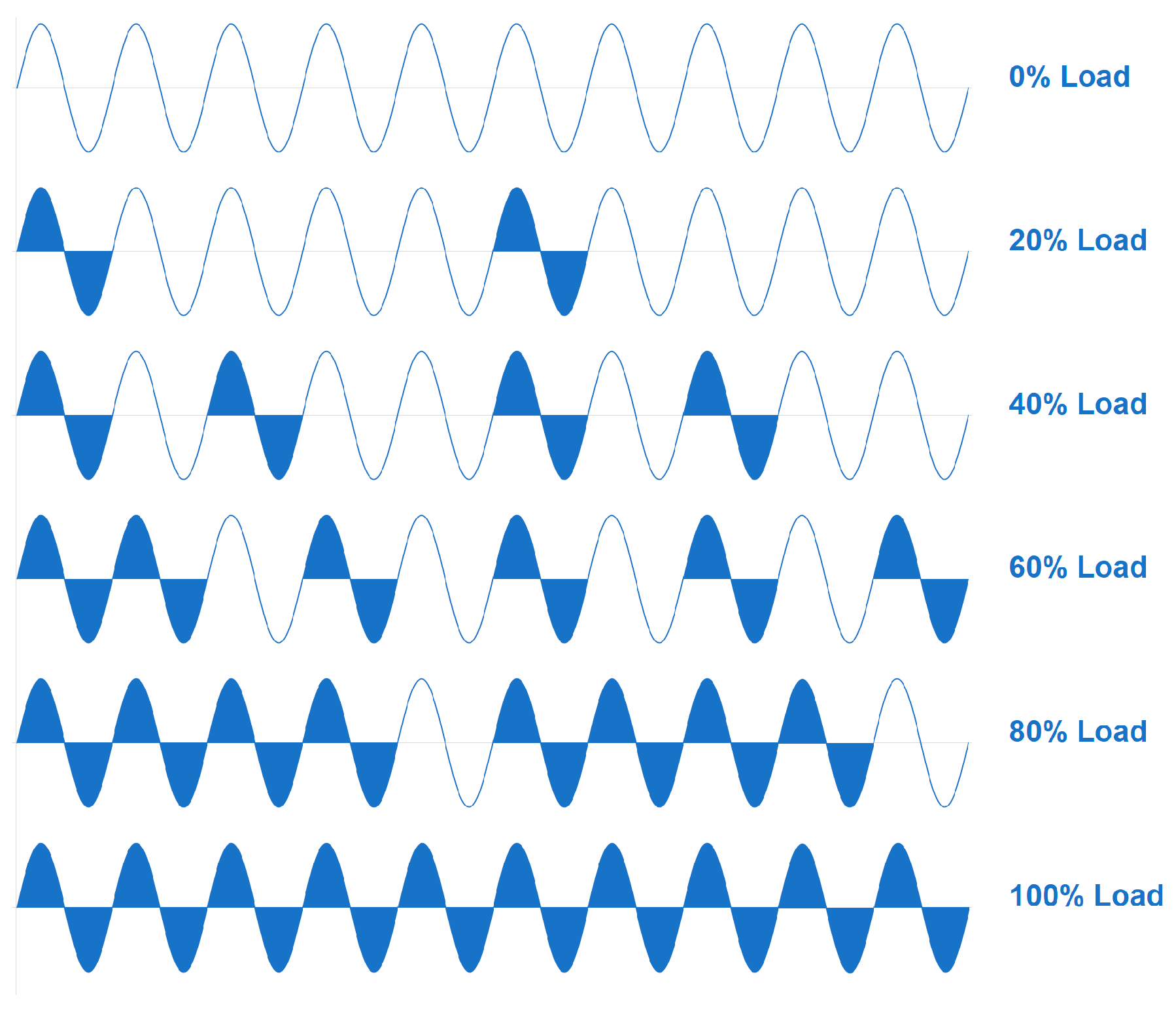
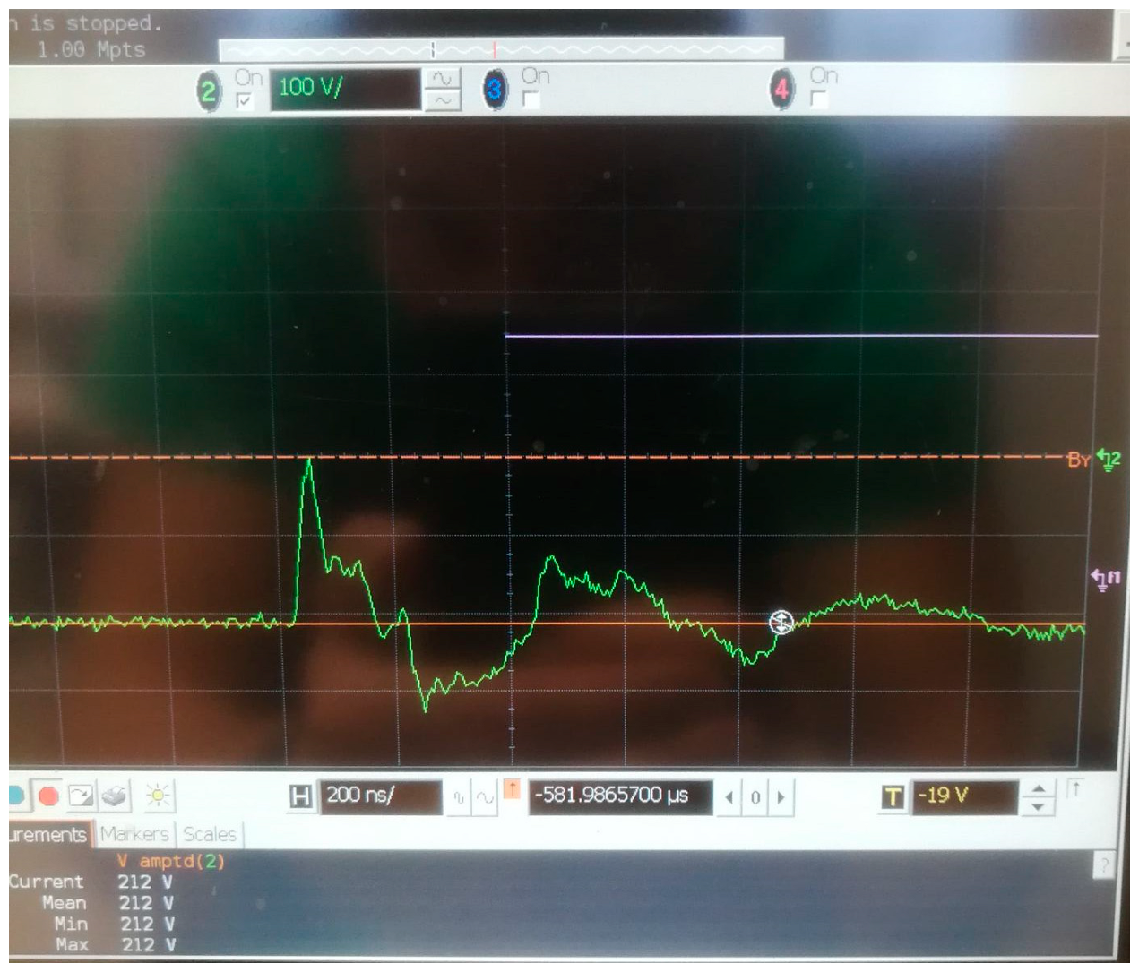
2.3. PWM on AC Bus Average Power Control Method
2.4. PWM on DC Bus Average Power Control Method
3. Comparison of Power Control Methods
- Versatile for implementation in different systems;
- Not harmful to other devices in a system;
- A cost-effective solution.
3.1. Versatility Comparison of Power Control Methods
3.2. Not Harmful to Other Devices in a System
3.3. Cost Evaluation of Power Control Methods
3.4. Summary of Comparison of Power Control Methods
4. Discussion
5. Conclusions
Author Contributions
Funding
Institutional Review Board Statement
Informed Consent Statement
Data Availability Statement
Conflicts of Interest
References
- Zelba, M.; Deveikis, T.; Barakauskas, J.; Baronas, A.; Gudzius, S.; Jonaitis, A.; Giannakis, A. A Grid-Tied Inverter with Renewable Energy Source Integration in an Off-Grid System with a Functional Experimental Prototype. Sustainability 2022, 14, 13110. [Google Scholar] [CrossRef]
- Lu, N.; Vanouni, M. Passive energy storage using distributed electric loads with thermal storage. J. Mod. Power Syst. Clean Energy 2013, 1, 264–274. [Google Scholar] [CrossRef] [Green Version]
- Tasdighi, M.; Ghasemi, H.; Rahimi-Kian, A. Residential Microgrid Scheduling Based on Smart Meters Data and Temperature Dependent Thermal Load Modeling. IEEE Trans. Smart Grid 2013, 5, 349–357. [Google Scholar] [CrossRef]
- Tahir, M.F.; Haoyong, C.; Mehmood, K.; Ali, N.; Bhutto, J.A. Integrated Energy System Modeling of China for 2020 by Incorporating Demand Response, Heat Pump and Thermal Storage. IEEE Access 2019, 7, 40095–40108. [Google Scholar] [CrossRef]
- Anvari-Moghaddam, A.; Monsef, H.; Rahimi-Kian, A. Optimal Smart Home Energy Management Considering Energy Saving and a Comfortable Lifestyle. IEEE Trans. Smart Grid 2014, 6, 324–332. [Google Scholar] [CrossRef]
- Nirmal, M.C.M.; Sruthi, M.; Jayaprakash, P. Control of a Pumped Hydro Storage Power Plant Supported Solar PV Generation System for Grid-Side Energy Management. In Proceedings of the 2021 IEEE 4th International Conference on Computing, Power and Communication Technologies (GUCON), Kuala Lumpur, Malaysia, 24–26 September 2021. [Google Scholar]
- Abdalla, S.M.; Saad, S.M.; El Naily, N.; Bukra, O.A. Seawater Pumped Hydro Energy Storage in Libya Part I: Location, Design and Calculations. In Proceedings of the 2021 IEEE 1st International Maghreb Meeting of the Conference on Sciences and Techniques of Automatic Control and Computer Engineering MI-STA, Tripoli, Libya, 25–27 May 2021. [Google Scholar]
- Black, M.; Strbac, G. Value of Bulk Energy Storage for Managing Wind Power Fluctuations. IEEE Trans. Energy Convers. 2007, 22, 197–205. [Google Scholar] [CrossRef]
- Tahir, M.F.; Haoyong, C.; Khan, A.; Javed, M.S.; Laraik, N.A.; Mehmood, K. Optimizing Size of Variable Renewable Energy Sources by Incorporating Energy Storage and Demand Response. IEEE Access 2019, 7, 103115–103126. [Google Scholar] [CrossRef]
- Nayanatara, C.; Divya, S.; Mahalakshmi, E. Micro-Grid Management Strategy with the Integration of Renewable Energy Using IoT. In Proceedings of the 2018 International Conference on Computation of Power, Energy, Information and Communication (ICCPEIC), Chennai, India, 28–29 March 2018. [Google Scholar]
- Bao, Z.; Qiu, W.; Wu, L.; Zhai, F.; Xu, W.; Li, B.; Li, Z. Optimal Multi-Timescale Demand Side Scheduling Considering Dynamic Scenarios of Electricity Demand. IEEE Trans. Smart Grid 2018, 10, 2428–2439. [Google Scholar] [CrossRef]
- Karapetyan, A.; Khonji, M.; Chau, S.C.-K.; Elbassioni, K.; Zeineldin, H.H.; El-Fouly, T.H.; Al-Durra, A. A Competitive Scheduling Algorithm for Online Demand Response in Islanded Microgrids. IEEE Trans. Power Syst. 2020, 36, 3430–3440. [Google Scholar] [CrossRef]
- Koutsopoulos, I.; Tassiulas, L. Optimal Control Policies for Power Demand Scheduling in the Smart Grid. IEEE J. Sel. Areas Commun. 2012, 30, 1049–1060. [Google Scholar] [CrossRef]
- Qayyum, F.A.; Naeem, M.; Khwaja, A.S.; Anpalagan, A.; Guan, L.; Venkatesh, B. Appliance Scheduling Optimization in Smart Home Networks. IEEE Access 2015, 3, 2176–2190. [Google Scholar] [CrossRef]
- Li, D.; Jayaweera, S.K. Distributed Smart-Home Decision-Making in a Hierarchical Interactive Smart Grid Architecture. IEEE Trans. Parallel Distrib. Syst. 2014, 26, 75–84. [Google Scholar] [CrossRef]
- Latif, A.; Paul, M.; Das, D.C.; Hussain, S.M.S.; Ustun, T.S. Price Based Demand Response for Optimal Frequency Stabilization in ORC Solar Thermal Based Isolated Hybrid Microgrid under Salp Swarm Technique. Electronics 2020, 9, 2209. [Google Scholar] [CrossRef]
- Sanjari, M.J.; Karami, H.; Gooi, H.B. Analytical Rule-Based Approach to Online Optimal Control of Smart Residential Energy System. IEEE Trans. Ind. Inform. 2017, 13, 1586–1597. [Google Scholar] [CrossRef]
- Huang, Q.; Jia, Q.-S.; Guan, X. Robust Scheduling of EV Charging Load With Uncertain Wind Power Integration. IEEE Trans. Smart Grid 2016, 9, 1043–1054. [Google Scholar] [CrossRef]
- Patterson, M.; Macia, N.F.; Kannan, A.M. Hybrid Microgrid Model Based on Solar Photovoltaic Battery Fuel Cell System for Intermittent Load Applications. IEEE Trans. Energy Convers. 2014, 30, 359–366. [Google Scholar] [CrossRef]
- Agbossou, K.; Kolhe, M.; Hamelin, J.; Bose, T. Performance of a Stand-Alone Renewable Energy System Based on Energy Storage as Hydrogen. IEEE Trans. Energy Convers. 2004, 19, 633–640. [Google Scholar] [CrossRef]
- Tushar, M.H.K.; Assi, C.; Maier, M.; Uddin, M.F. Smart Microgrids: Optimal Joint Scheduling for Electric Vehicles and Home Appliances. IEEE Trans. Smart Grid 2014, 5, 239–250. [Google Scholar] [CrossRef]
- Singh, M.; Kumar, P.; Kar, I.; Kumar, N. A real-time smart charging station for EVs designed for V2G scenario and its coordination with renewable energy sources. In Proceedings of the 2016 IEEE Power and Energy Society General Meeting (PESGM), Boston, MA, USA, 17–21 July 2016. [Google Scholar]
- Arun, S.L.; Selvan, M.P. Intelligent Residential Energy Management System for Dynamic Demand Response in Smart Buildings. IEEE Syst. J. 2017, 12, 1329–1340. [Google Scholar] [CrossRef]
- Arriaga, M.; Cañizares, C.A.; Kazerani, M. Renewable Energy Alternatives for Remote Communities in Northern Ontario, Canada. IEEE Trans. Sustain. Energy 2013, 4, 661–670. [Google Scholar] [CrossRef]
- Nehrir, M.; Lameres, B.; Venkataramanan, G.; Gerez, V.; Alvarado, L. An approach to evaluate the general performance of stand-alone wind/photovoltaic generating systems. IEEE Trans. Energy Convers. 2000, 15, 433–439. [Google Scholar] [CrossRef] [Green Version]
- Ustun, T.S.; Hussain, S.M.S. Standardized Communication Model for Home Energy Management System. IEEE Access 2020, 8, 180067–180075. [Google Scholar] [CrossRef]
- Hirose, T.; Matsuo, H. Standalone Hybrid Wind-Solar Power Generation System Applying Dump Power Control without Dump Load. IEEE Trans. Ind. Electron. 2011, 59, 988–997. [Google Scholar] [CrossRef]
- Abbey, C.; Li, W.; Joos, G. An Online Control Algorithm for Application of a Hybrid ESS to a Wind–Diesel System. IEEE Trans. Ind. Electron. 2010, 57, 3896–3904. [Google Scholar] [CrossRef]
- Manjarres, P.; Malik, O. Frequency regulation by fuzzy and binary control in a hybrid islanded microgrid. J. Mod. Power Syst. Clean Energy 2014, 3, 429–439. [Google Scholar] [CrossRef] [Green Version]
- Mahmood, H.; Michaelson, D.; Jiang, J. A Power Management Strategy for PV/Battery Hybrid Systems in Islanded Microgrids. IEEE J. Emerg. Sel. Top. Power Electron. 2014, 2, 870–882. [Google Scholar] [CrossRef]
- Mori, M.; Gutiérrez, M.; Casero, P. Micro-grid design and life-cycle assessment of a mountain hut’s stand-alone energy system with hydrogen used for seasonal storage. Int. J. Hydrogen Energy 2021, 46, 29706–29723. [Google Scholar] [CrossRef]
- Esteban, L.J.; Andrea, M.; Enrico, P.; Harm, L.; Ettore, B. Modelling and Control of a Grid-Connected RES-Hydrogen Hybrid Microgrid. Energies 2021, 14, 1540. [Google Scholar]
- Jose, C.M.J.; Francisca, S.M.; Jose, M.A.; Francisco, J.V.; Antonio, J.C. An Optimized Balance of Plant for a Medium-Size PEM Electrolyzer: Design, Control and Physical Implementation. Electronics 2020, 9, 871. [Google Scholar]
- An, S.; Wang, H.; Yuan, X. Real-Time Optimal Operation Control of Micro Energy Grid Coupling with Electricity-Thermal-Gas Considering Prosumer Characteristics. IEEE Access 2020, 8, 216566–216579. [Google Scholar] [CrossRef]
- Venkatraman, K.; Reddy, B.D.; Selvan, M.P.; Moorthi, S.; Kumaresan, N.; Gounden, N.A. Online condition monitoring and power management system for standalone micro-grid using FPGAs. IET Gener. Transm. Distrib. 2016, 10, 3875–3884. [Google Scholar] [CrossRef]
- Jiang, W.; Yang, C.; Liu, Z.; Liang, M.; Li, P.; Zhou, G. A Hierarchical Control Structure for Distributed Energy Storage System in DC Micro-Grid. IEEE Access 2019, 7, 128787–128795. [Google Scholar] [CrossRef]
- Hosseinzadeh, M.; Salmasi, F.R. Power management of an isolated hybrid AC/DC micro-grid with fuzzy control of battery banks. In Proceedings of the IET Renewable Power Generation, Loughborough, UK, 23–25 April 2014. [Google Scholar]
- Song, M.; Shi, J.; Liu, Y.; Xu, Y.; Hu, N.; Tang, Y.; Ren, L.; Li, J. 100 kJ/50 kW HTS SMES for Micro-Grid. IEEE Trans. Appl. Supercond. 2014, 25, 5700506. [Google Scholar] [CrossRef]
- Audrius, J.; Renata, M.; Tomas, D. Dynamic model of wind power balancing in hybrid power system. Turk. J. Electr. Eng. Comput. Sci. 2017, 25, 222–234. [Google Scholar]
- Salim, H.M.; Nacereddine, B.-T.; Faouzi, D. Analysis of the reliability of photovoltaic-micro-wind based hybrid power system with battery storage for optimized electricity generation at Tlemcen, north west Algeria. Arch. Thermodyn. 2019, 40, 161–185. [Google Scholar]
- Mayo-Maldonado, J.C.; Valdez-Resendiz, J.E.; Rosas-Caro, J.C. Power Balancing Approach for Modeling and Stabilization of DC Networks. IEEE Trans. Smart Grid 2018, 10, 4188–4200. [Google Scholar] [CrossRef]
- Al Kez, D.; Foley, A.M.; Muyeen, S.M.; Morrow, D.J. Manipulation of Static and Dynamic Data Center Power Responses to Support Grid Operations. IEEE Access 2020, 8, 182078–182091. [Google Scholar] [CrossRef]
- Jis, B.; Wu, H.; Li, Y. Flexible On-grid and Microgrid Control Strategy of Photovoltaic Energy Storage System Based on VSG Technology. In Proceedings of the 2021 IEEE 5th Conference on Energy Internet and Energy System Integration (EI2), Taiyuan, China, 25 February 2022. [Google Scholar]
- Byoung-Hee, L.; Ki-Bum, P.; Chong-Eun, K.; Gun-Woo, M. No-Load Power Reduction Technique for AC/DC Adapters. IEEE Trans. Power Electron. 2012, 27, 3685–3694. [Google Scholar]
- Smith, J.R. Programming the PIC Microcontroller with MBASIC; Elsevier Inc.: Maryland Heights, MO, USA, 2005; Chapter 23—AC Power Control; 543p. [Google Scholar]
- Selvaperumal, S.; Krishnamoorthy, N.; Prabhakar, G. A novel source side power quality improved soft starting of three-phase induction motor using a symmetrical angle controller through pic microcontroller. Bull. Pol. Acad. Sci.-Tech. Sci. 2021, 69, e136746. [Google Scholar]
- He, L.; Zeng, T.; Zhang, J. The Regulation Characteristics of Bridge Modular Switched-Capacitor Ac-Ac Converter. IEEE Access 2019, 7, 147683–147693. [Google Scholar] [CrossRef]
- Zhang, Y.; Ruan, X. Three-Phase AC-AC Converter with Controllable Phase and Amplitude. IEEE Trans. Ind. Electron. 2015, 62, 5689–5699. [Google Scholar] [CrossRef]
- Hyeon-gyu, C.; Jung-Ik, H. Dynamic current control using synchronous pulse-width modulation for permanent magnet machines. J. Power Electron. 2020, 20, 501–510. [Google Scholar]
- Gungor, B.; Nihat, O. A Novel Control Technique for Soft-switching Sinusoidal Pulse Width Modulation Inverter. Electr. Power Compon. Syst. 2010, 39, 31–45. [Google Scholar]
- Matthias, S.; Josef, G.; Jan, E.; Markus, L. Influence of pulse width modulated auxiliary consumers on battery aging in electric vehicles. J. Energy Storage 2022, 48, 104009. [Google Scholar]
- Zhang, M.; Liu, Y.; Li, D.; Cui, X.; Wang, L.; Li, L.; Wang, K. Electrochemical Impedance Spectroscopy: A New Chapter in the Fast and Accurate Estimation of the State of Health for Lithium-Ion Batteries. Energies 2023, 16, 1599. [Google Scholar] [CrossRef]
- Li, W.; Niimi, Y.; Orino, Y.; Hirata, S.; Kurosawa, M.K. A Frequency Synchronization Method for a Self-Oscillating PWM Signal Generator. IEEE Trans. Circuits Syst. II Express Briefs 2014, 61, 244–248. [Google Scholar]
- Zhang, L.; Born, R.; Zhao, X.; Gu, B.; Lai, J.-S.; Ma, H. A Parabolic Voltage Control Strategy for Burst-Mode Converters with Constant Burst Frequency and Eliminated Audible Noise. IEEE Trans. Power Electron. 2016, 31, 8572–8580. [Google Scholar] [CrossRef]
- Kim, J.W.; Choi, S.M.; Kim, K.T. Variable On-time Control of the Critical Conduction Mode Boost Power Factor Correction Converter to Improve Zero-crossing Distortion. In Proceedings of the 2005 International Conference on Power Electronics and Drives Systems, Kuala Lumpur, Malaysia, 18 April 2006. [Google Scholar]
- Ambhorkar, K.; Rana, A.K.; Jain, P.; Tutakne, D.R. Single phase AC-AC converter with improved power factor for efficient control of fan motors. In Proceedings of the 2016 7th India International Conference on Power Electronics (IICPE), Patiala, India, 23 October 2017. [Google Scholar]
- Yun, S.J.; Yun, Y.K.; Kim, Y.S. A Low Flicker TRIAC Dimmable Direct AC LED Driver for Always-on LED Arrays. IEEE Access 2020, 8, 198925–198934. [Google Scholar] [CrossRef]
- Kadota, M.; Shoji, H.; Hirose, H.; Hatakeyama, A.; Wada, K. A Turn-off Delay Controlled Bleeder Circuit for Single-Stage TRIAC Dimmable LED Driver with Small-Scale Implementation and Low Output Current Ripple. IEEE Trans. Power Electron. 2019, 34, 10069–10081. [Google Scholar] [CrossRef]
- Campo, J.C.; Vaquero, J.; Perez, M.A.; Martinez, S. Dual-tap chopping stabilizer with mixed seminatural switching. Analysis and synthesis. IEEE Trans. Power Deliv. 2005, 20, 2315–2326. [Google Scholar] [CrossRef]
- Yin, B.; Oruganti, R.; Panda, S.K.; Bhat, A.K.S. An Output-Power-Control Strategy for a Three-Phase PWM Rectifier under Unbalanced Supply Conditions. IEEE Trans. Ind. Electron. 2008, 55, 2140–2151. [Google Scholar] [CrossRef]
- Martínez-Treviño, B.A.; El Aroudi, A.; Valderrama-Blavi, H.; Cid-Pastor, A.; Vidal-Idiarte, E.; Martinez-Salamero, L. PWM Nonlinear Control with Load Power Estimation for Output Voltage Regulation of a Boost Converter with Constant Power Load. IEEE Trans. Power Electron. 2021, 36, 2143–2153. [Google Scholar] [CrossRef]


| Excess Power Utilization Option | Reference | Drawback |
|---|---|---|
| Heat/thermal storage | [2,3,4,5] | Excess power is utilized in fixed power, and therefore, fixed power causes microgrid system battery discharge. |
| Pump storage | [6,7,8,9] | Complicated to implement both at the commercial and residential scale. |
| Scheduling | [10,11,12,13,14,15,16] | Excess power is utilized at the cost of consumer comfort. |
| V2G/G2V; fuel cell | [17,18,19,20,21,22] | It expands the accumulated energy level in a microgrid system, and therefore, it solves the issue only temporarily. |
| Dump load | [23,24,25] | Excess power is utilized in fixed power, and therefore, fixed power causes microgrid system battery discharge. |
| Inverter/system control via communication | [26,27,28,29,30] | Complicated to implement in different designs of systems. Not feasible to create a plug and play solution. |
| Power Control Method | Versatile | Cost-Efficient | No Filtering Needed |
|---|---|---|---|
| Burst | Yes | Yes | Yes |
| Phase delay | Yes | No | No |
| PWM AC bus | Yes | No | No |
| PWM DC bus | No | Yes | Yes |
Disclaimer/Publisher’s Note: The statements, opinions and data contained in all publications are solely those of the individual author(s) and contributor(s) and not of MDPI and/or the editor(s). MDPI and/or the editor(s) disclaim responsibility for any injury to people or property resulting from any ideas, methods, instructions or products referred to in the content. |
© 2023 by the authors. Licensee MDPI, Basel, Switzerland. This article is an open access article distributed under the terms and conditions of the Creative Commons Attribution (CC BY) license (https://creativecommons.org/licenses/by/4.0/).
Share and Cite
Zelba, M.; Deveikis, T.; Gudžius, S.; Jonaitis, A.; Bandza, A. Review of Power Control Methods for a Variable Average Power Load Model Designed for a Microgrid with Non-Controllable Renewable Energy Sources. Sustainability 2023, 15, 9100. https://doi.org/10.3390/su15119100
Zelba M, Deveikis T, Gudžius S, Jonaitis A, Bandza A. Review of Power Control Methods for a Variable Average Power Load Model Designed for a Microgrid with Non-Controllable Renewable Energy Sources. Sustainability. 2023; 15(11):9100. https://doi.org/10.3390/su15119100
Chicago/Turabian StyleZelba, Mantas, Tomas Deveikis, Saulius Gudžius, Audrius Jonaitis, and Almantas Bandza. 2023. "Review of Power Control Methods for a Variable Average Power Load Model Designed for a Microgrid with Non-Controllable Renewable Energy Sources" Sustainability 15, no. 11: 9100. https://doi.org/10.3390/su15119100