Article

Traffic Manager Development for a Roundabout Crossed by Autonomous and Connected Vehicles Using V2I Architecture

1
IFP Energies Nouvelles, 1–4 Avenue de Bois-Préau, 92852 Rueil-Malmaison, France
2
IFP School, 228–232 Avenue Napoléon Bonaparte, CEDEX, 92852 Rueil-Malmaison, France
3
ALSTOM, Rue Albert Dhalenne 48, 93400 Saint Ouen, France
*
Author to whom correspondence should be addressed.
Sustainability 2023, 15(12), 9247; https://doi.org/10.3390/su15129247
Submission received: 11 April 2023 / Revised: 12 May 2023 / Accepted: 29 May 2023 / Published: 7 June 2023
(This article belongs to the Special Issue Safety and Sustainability in Future Transportation)

Abstract

:
Connected Autonomous Vehicle (CAV) is considered as a proposal toward sustainable mobility. In order to succeed in a sustainable mobility solution, “CAV” or more precisely “CAV Transport System” should prove to be low energy, safe, and allow better performances than human-driven vehicles. This paper will propose a system architecture for a sustainable CAV Transport System on a standard scenario: crossing a roundabout. Nowadays, roundabouts are very common and practical crossing alternatives to improve the traffic flow and increase safety. This study aims to simulate and analyze the behavior of connected autonomous vehicles crossing a roundabout using a V2I (vehicle-to-infrastructure) architecture. The vehicles are exchanging information with a so-called central signaling unit. All vehicles are exchanging their position, speed, and target destination. The central signaling unit has a global view of the system compared to each ego vehicle (has more local than global information); thus, can safely and efficiently manage the traffic of the vehicles in the roundabout using a standard signaling block strategy. This strategy of decision of the central signaling unit (CSU) is performed by dividing the roundabout into several zones/blocks which can be booked by only one vehicle at a time. A solver, reproducing a vehicle’s behavior and dynamics, computes the trajectory and velocity of each vehicle depending on its surroundings. Finally, a graphical representation is used and implemented to facilitate the analysis and visualization of the roundabout crossing. The vehicle flow performance of the developed traffic control model is compared with SUMO.

1. Introduction

In the future, the connected and autonomous vehicle (CAV) will be seen as a means of not only meeting the requirements for individual comfort, safety, and the potential to improve the flow and fluidity of transport [1,2], but it will also face the challenges of environmental issues to offer future sustainable mobility. Therefore, there will be a significant need in the future for in-depth scientific knowledge and the creation of new skills in the field of CAVs. In this field, new technologies and new business models are transforming not only vehicles but also the whole ecosystem around them. These massive changes on the horizon represent an opportunity to move toward a transport system that is more efficient, safer, and less polluting. However, new transport technologies, on their own, will not spontaneously make our lives better without upgrading our transport systems and policies to the 21st century. Recent years have seen the development and the emergence of new cooperative intelligent transportation systems (C-ITSs) where data sent via information and communication technologies (ICTs) have the potential to enhance traffic conditions instead of extending physical infrastructure; thereby introducing new business models and reduction of environmental impact. These technologies along with the introduction of new features in autonomous vehicles bring new challenges in terms of evaluation and performance of connected and automated vehicles (CAVs) [3].
Roundabout intersections have recently become very popular, especially in Europe where they have gradually proven their effectiveness and safety [4,5,6]. Therefore, if the popularization of autonomous vehicles is to be realized, the decision-making problem of autonomous vehicles in roundabout intersections must be solved with a robust safety concept. If autonomous vehicles cannot make safe, reasonable decisions, they will undoubtedly reduce the efficiency of traffic operation, increase the waiting time of each vehicle, and even bring the risk of traffic accidents. The most difficult part to develop is crossroads and, with five hundred to eight hundred new roundabouts created per year, in France, for example, manufacturers need to find a way to deal with autonomous vehicles in roundabouts and optimize the vehicle flow inside this type of intersection [7].
Different strategies can be used to cross an intersection with an autonomous vehicle. Wei Wang et al. [8] propose to use image processing and computer vision technology. The weaknesses of this strategy are the accuracy, safety proof of neural network, and real-time issues. Xu, X. et al. [9] propose to use cloud computing methods to improve data processing efficiency. Furthermore, García Cuenca, L. et al. [10] propose to use reinforcement learning in addition to q-learning to cross a roundabout with autonomous vehicles.
Other research studies provide insights into various aspects of traffic flow at roundabouts, including capacity analysis, performance evaluation, and the impact of autonomous vehicles on operations [11,12,13,14,15].
A new proposal of this study is to elaborate a solution that can fit with every roundabout. Vehicle-to-infrastructure communication may be a solution for autonomous driving in a roundabout. The V2I, vehicle-to-infrastructure, process starts with the infrastructure collecting information about approaching vehicles. It then assigns a global path around the roundabout based on the destination and current position, in the same way as path planning for platooning on highways [16,17,18]. To do so, the infrastructure compares a pre-assigned trajectory with other vehicles’ trajectories and checks if there is a risk of interference. The vehicles request a space resource through a booking process toward infrastructure. If the booking is successful, infrastructure then allocates the vehicle trajectory. This space resource is then not considered as free, but rather as booked. To achieve autonomous driving, each vehicle will generate control variables to follow the allocated trajectory inside their booked space while avoiding obstacles in their way either by braking, accelerating, or cruising at the same speed. In the case of a faulty ego vehicle trespassing, its booked zone (not fulfilling end of authority), the central signaling unit (CSU), will request an emergency stop for all vehicles in the roundabout under supervision.
This proposed system architecture based on a CSU and on autonomous vehicles offers new possibilities to apportion the management of the risk of collision. Usually, crossing a roundabout for autonomous vehicles is not seen as a global system but as an aggregation of decentralized multiple vehicles. Safety then relies solely on each vehicle for taking care mostly of its own safety (e.g., through safe gap/headway). Therefore, in this case, the safety of the global system is not a feature in itself but is achieved by the optimistic aggregation of multiple egoistic safeties. Implementing common driving rules into each vehicle logic mimics the system safety of human drivers but cannot be proven equivalent. The high level of safety to be proven can make it difficult to reach a sustainable cost in the best case, or even simply impossible to demonstrate due to the use of nonpredictable artificial intelligence (AI). On the contrary, the proposed system architecture includes a CSU whose aim is to offer the global system level and then a possibility to tackle this “transport system” safety and, most important characteristic, can be proven safe against common safety integrity level software methods (ISO 26262 [19] or EN 50657 [20] for example). The CSU offers a new functional safety barrier against the risk of collision that is independent of each ego vehicle’s sensors and control. It is then possible to reduce the safety level allocated to ego vehicle sensors and control to a technically/economically reasonable level.
This paper is structured as follows: Section 2 describes the system architecture, the generation of vehicles, and their characteristics. Section 3 further explains the methodology to manage the traffic in the given system, its implementation, and the design of the simulation interface. Section 4 performs a parametric study of the system to prove the adaptability of the developed algorithm. Finally, Section 5 highlights the results obtained and suggests further improvements.

2. Materials

2.1. System and Network Architecture

The system is illustrated in Figure 1 and is made of a network, e.g., roundabout, the users, e.g., vehicles, and a central signaling unit (CSU) able to manage the users in the network safely and optimally. The central signaling unit must know the position of each user in the network to manage them and be aware of interactions. It has been assumed in this study that all users of the network can communicate their positions to the central unit. This assumption is technically realistic as it is already possible to share real-time vehicle positions. However, it is still difficult to implement for competition and confidential issues [21].
To deal with the vehicles in the system, the roundabout has been divided into a fixed number of zones with a maximum of one vehicle per zone to ensure safety. A similar architecture called Absolute Block Signaling is frequently used in train signalization [22]. This zoning strategy is different from the classical car following models [23] as it does rely on the infrastructure to manage traffic and not on forward vehicles. Pushing the zones to an infinitesimal size led to a moving block architecture. Takeuchi, H. et al. [24] showed that pure moving block signaling leads to a higher capacity of the network but also requires more computational efforts. Section 4.2 studies the effect of zone size on traffic performance. Figure 1 illustrates an overview of the system with the zoning of the roundabout and the vehicles interacting with the CSU.
Some assumptions have been made on the system concerning the interaction between the central signaling unit, the vehicles, and the roundabout:
-
The dynamic of the vehicle is modeled with a bicycle model [25,26].
-
All the vehicles in the system can send and receive information from a traffic manager.
-
The trajectories of the vehicles entering the roundabout are predefined and randomly chosen.
-
All the vehicles in the system react and instantaneously execute an order received by the CSU.
-
Software resolution time taken by the traffic manager is neglected in this study.
-
The communication network characteristic between the infrastructure and vehicles is not considered in this study.

2.2. Central Signaling Unit

Working with a zoning strategy, the CSU will list all the zones of the roundabout and will stock each zones size, if they are available, and if not, which vehicle booked it. The vehicles in the roundabout make requests to the CSU to book the zones they desire, and the CSU replies with a movement authority. This way, the CSU has a global view of the network and acts as a flag for the movement of the vehicle. It acts as the infrastructure side in vehicle-to-infrastructure communication [27,28].

2.3. Vehicle Generation and Database

To simulate the system, a diversity of vehicles is created with random shapes, sizes, entries and exits, speeds, etc. for a given simulation. Once the vehicles have been randomly constituted, it is important to construct their path through the roundabout. Depending on the entry and exit, the path is drawn according to the conventions of the traffic regulation [29], as can be seen in Figure 2. Vehicles will know in which zones they should go through and will use their centers to locate their waypoints at each time step. A third order interpolation (Matlab function “3rd order polynomial”) is performed to determine the path to take between these waypoints depending on vehicle speed. The vehicle then evolves at each time step according to its speed and the waypoint’s location.
Vehicles are stocked in a vehicle database with the following information: identifier, size, entry, exit, entry time, entry speed, path, position, distance, and zones to book. This vehicle database will communicate with the infrastructure and act as the vehicle side of the vehicle-to-infrastructure communication [27,28]. Please note that the vehicles are not communicating between them.
During the passage of the vehicle through the roundabout, the speed of the vehicle must be limited by traffic laws but must also be limited to improve passengers’ comfort. Regarding this point, Schramm et al. [30] advise to limit the lateral acceleration suffered by the passenger to 0.4 g. The lateral acceleration is computed thanks to a model of vehicle dynamics [30]:
a y ,   m a x = v m a x 2   R c u r v a t u r e  
where a y ,   m a x is the maximum lateral acceleration [m/ s 2 ], v m a x 2 is the maximum permitted vehicle speed [m/s], and R c u r v a t u r e is the curvature radius [m].
The radius of curvature at each moment is calculated for each vehicle from different points that make up its constructed path. Knowing the radius of curvature taken by the vehicle and the admissible acceleration, the vehicle calculates the maximum speed it can take.
To have an overview of the trends of energy consumption during the system simulation, a simple model of an electric vehicle has been used. The characteristics of this model are depicted in the Table 1.
Using these assumptions, it is now possible to obtain an overview of the trends concerning vehicle consumption, with dedicated equations [30].
F t o t   [ N ] = M v e h i c l e     ×   g     ×   C r r 1000 + 1 2 ρ S x C x V 2 + a x M v e h i c l e  
T   [ Nm ] = F t o t     ×   R w R
N   [ rad / s ] = V     ×   1000     ×   R     ×   π 60     ×   2 π     ×   R w       ×   30
P   [ W ] = T     ×   N
C   [ Wh / km ] = P     ×   ( t o u t t i n ) T o t a l D i s t a n c e

3. Methodology

To deal with the vehicles entering the roundabout, a traffic manager called communication-based vehicle control (CBVC) has been built. The first function of this traffic manager is to ensure safety. In addition, it must follow traffic laws and optimize the traffic flow through the network.

3.1. Algorithm Architecture

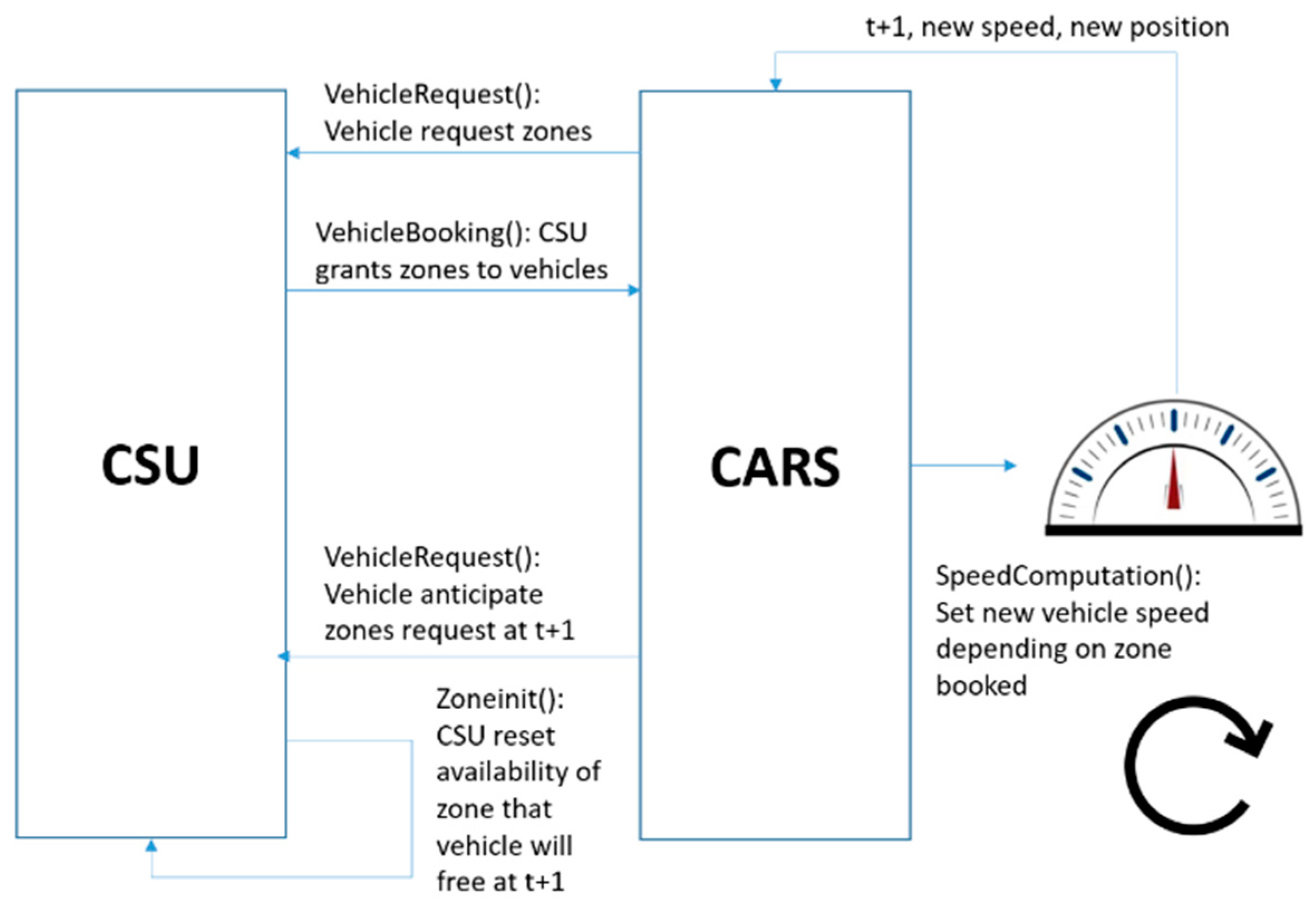
The communication-based vehicle control (CBVC) algorithm is following an object-oriented programming organization (Figure 3) [31]. It comprises a set of functions that are separated into blocks according to their functionalities. Objects are initialized due to different functions, as defined in Figure 4. All these objects are then fed to a solver, as described in Section 3.2. At the end of the solving process, the waypoints and speed profile of each vehicle will be extracted from the solver to create a graphical view of the driving scenario. Results such as vehicle crossing time, speed, consumption, and overall traffic flow can be plotted from the data obtained.

3.2. Solver Principle

The traffic manager works in the following way: Each vehicle will request the zones it needs to move forward. The zones required are computed based on the actual speed of the vehicle and its characteristics. The forward length required by the vehicle is chosen as the maximum distance between the perspective it will travel at its actual speed in two seconds and the emergency braking distance it needs at its speed. The emergency braking distance is computed according to the equation taken as a reference for the French highway code.
D e m e r g e n c y = 3 2 ( V x 10 ) 2  
where D e m e r g e n c y is the Emergency distance [m], and V x is the vehicle speed.
Once the zones to be booked are known, the vehicle will make a request to the central unit. The central unit will take a decision following a decision tree. Once the central unit has rejected a zone request by a given vehicle, the following zone requests by this vehicle during the same time step are rejected too.
Once the vehicle knows how many zones the CSU has allocated to it and the number of zones it has requested, the vehicle can adjust its speed. If the number of zones allocated is higher than the number of zones requested, the vehicle will speed up to the maximum speed. If the number of zone requests is equal to the zone allocated, the vehicle will cruise at its actual speed. Otherwise, the vehicle will decelerate depending on how many zones the CSU rejected from the initial zone request.
At a time, t, the solver deals with each first zone requested by each vehicle one by one, depending on applied priority rules, and repeats the process until the last zone requested by each vehicle is analyzed.
The main functions used for this solving process are:
-
Vehicle request(): Computes the distance the vehicle has to book at the next time step depending on its speed and characteristics.
-
Vehicle booking(): Takes as input the vehicle’s request and zone availability to assign the zones to the different vehicles.
-
Speed computation(): Depending on the difference between the number of zones requested and the number of zones assigned, it will compute a speed for the vehicle.
-
Zoneinit(): CSU resets the availability of zones where the vehicle will be free at the next time step.

3.3. Driving Scenario Designer

After running the solver and obtaining the behavior of all the vehicles in the simulation at each time step, a graphic interface is used to realistically represent the scenario from the data obtained by the solver.
The Driving Scenario Designer module present on Matlab allows one to realize a video of all types of driving scenarios from some inputs. The Driving Scenario Designer takes as inputs the geometry of the roundabout and three vectors of the vehicle’s data calculated by the designed algorithm: the vehicle’s waypoints, vehicle’s speeds, and vehicle’s wait times at each time step.
In addition, it must also be informed of all the useful data on the vehicles which circulate: their class, a randomly given color, their name, their length and width, their entry time, and their exit time in the roundabout. The CBVC memorizes this information at each time step in the three different vectors and feeds the Driving Scenario Designer at the end of the simulation.

3.4. Reference Case Study

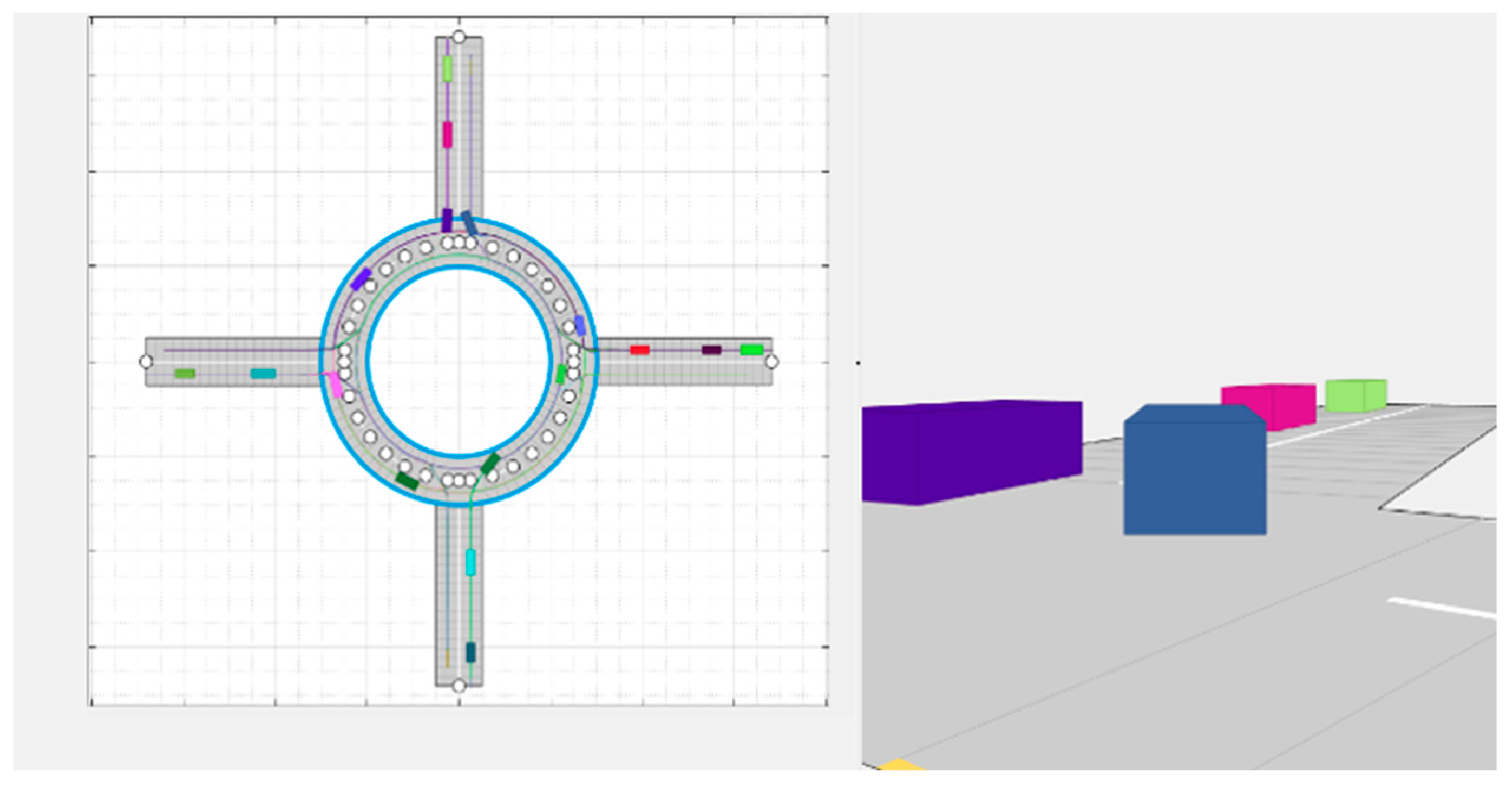
As depicted in Figure 5, the studied system is a four-entrance roundabout. The entrances/exits are simplified as straight, and the roundabout is assumed to be perfectly round. Apart from this, the roundabout parameters are completely tunable, such as:
-
Geometrical design parameters: number of in-roundabout lanes, number of lanes per entrance, or roundabout radius.
-
Algorithm accuracy parameters: number of roundabout zones between two entrances or time step for solving process.
-
Safety and comfort criteria: admissible lateral acceleration, speed limitation, or safety distance.
The influence of each of these parameters on roundabout performance is studied individually in further sections. For that, a reference case is chosen according to the Table 2. These values are chosen in coherence with a typical European average city’s roundabout.
Consistency of the simulations was verified. Firstly, the simulated roundabout had a typical size of 30 m for the inner radius [32]. Secondly, to cover a wide operating range and to generate tense traffic, the simulation was performed with vehicles arriving randomly at a frequency of 2 s, which is an upper bound to the vehicle capacity observed in this study. If there was a collision of vehicles during the simulation, the simulation stopped, and a flag was lifted. This flag was not observed during the simulations performed with the developed traffic manager. In addition, each simulation configuration performed one hundred times and results were averaged to obtain the most general results possible. To conclude, the traffic flow obtained with the simulation is of the same order as the traffic flow observed in real life by Demir, H.G. et al. [33] and comparable to the results obtained with the benchmark simulator, which is further discussed in Section 4.4.
Traffic congestion was regulated by the total number of vehicles crossing the roundabout during a driving scenario. For each driving scenario generated, the traffic can be depicted in three phases:
-
Phase 1: Accumulation phase—vehicles are progressively loading the empty roundabout until it reaches its full capacity. This phase duration is completely independent of the total number of vehicles crossing the roundabout.
-
Phase 2: Maximum flow capacity—roundabout is fully loaded while vehicles are still entering it. This is the best sample to be studied to evaluate the maximum roundabout performance in terms of flow, average vehicle speed, average crossing time, and average vehicle consumption. This phase duration is completely proportional to the total number of vehicles crossing the roundabout.
-
Phase 3: Decumulation phase—no more vehicles are entering the roundabout, the load is decreasing as vehicles are progressively leaving, until the roundabout becomes completely empty. This phase duration is completely independent of the total number of vehicles crossing the roundabout.
To better evaluate the roundabout performance, a significant number of vehicles had been chosen to maximize phase two duration compared to those of phases one and three. A quick study can show the impact of the total number of vehicles in a driving scenario on results, considering the reference case.
Figure 6 shows some trends in results for simulations of up to 100 vehicles. These results then become more stable for more than 100 vehicles as phases one and three are more and more diluted compared to phase three.
In the subsequent studies, 60 vehicles were used per driving scenario to obtain a good trade-off between a significant number of vehicles and the heaviness of algorithm calculations. These trends of up to 100 vehicles can be used to obtain an estimation of the results for more or fewer vehicles.
Lastly, the algorithm was set up to consider the conventional in-roundabout right-of-way: the priority is given to the vehicle inside the roundabout.
Another way was to remove this conventional right-of-way, using the assets of the algorithm to apply the “first come, first served” strategy as proposed by Martin-Gasulla et al. [34]: the vehicle that would reach the zone first with its current speed and within two seconds would book it. This strategy assumes that it could help achieve the best vehicle flow rate by respecting the fastest way of proceeding.
However, simulations can easily demonstrate that this second way of proceeding mostly leads to deadlock and overload of the roundabout, as shown in Figure 7, with a direct impact on roundabout performance (Table 3). Thus, these results validate the choice of respecting the conventional in-roundabout right-of-way.

4. Results

4.1. Roundabout Design

The roundabout design has a direct impact on roundabout performance in terms of traffic flow, average speed, average crossing time, and average vehicle consumption.
Lane number is an important design criterion of the roundabout. In the algorithm, a maximum of two lanes is considered, a third lane is only considered for higher vehicle flow up to 5000 veh/h. The reference case considers a roundabout with two lanes inside the roundabout and one lane per entrance, as seen in Figure 8, but other settings could be considered: reduce the number of roundabout lanes or increase the number of lanes per entrance. These other settings are depicted below.
Adding a second entry lane means one would be used by vehicles willing to turn right or go straight, while the second would be used by those turning left or executing a U-turn. As vehicle flow exceeds 1200 veh/h, a second exit lane is also recommended. The performance of different lane numbers can be evaluated in Table 4.
Second, in-roundabout lane benefits are obvious: average crossing time is clearly reduced as there is less locking in the roundabout. Thus, the average speed of each vehicle is increased, and so does the traffic flow. As the vehicles are less blocked, the re-acceleration phases are reduced; therefore, the consumption decreases. This validates the design of a roundabout with two lanes.
Concerning the number of lane(s) per entrance/exit, benefits are also clear, as more vehicles can enter the roundabout, allowing better vehicle flow, less stop and re-acceleration phase, and better average speed and consumption. However, this slightly increases average crossing times and reduces average speed as a vehicle can have more difficulty entering the roundabout due to higher traffic load. Thus, benefits should also be balanced by customer acceptance of these waiting times concerning this upgrade.
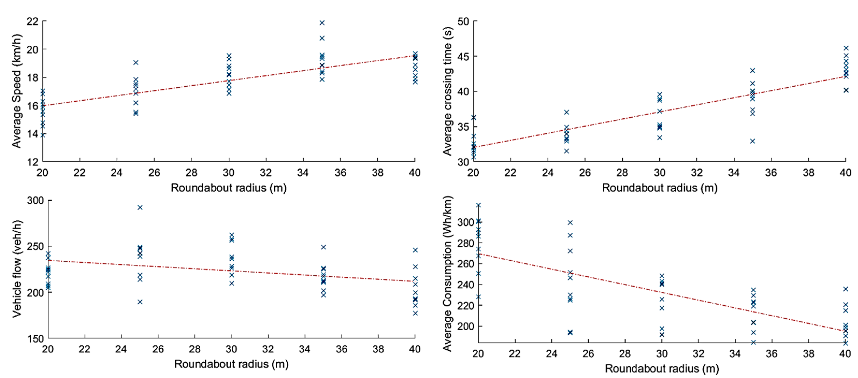
The other major design parameter of the roundabout is its radius. Increasing the roundabout radius means more space for each vehicle inside the roundabout, but also longer crossing distances. This has a big impact on roundabout performance, as can be seen in Figure 9.
Increasing the radius of the roundabout decreases the average flow of vehicles as crossing distances are increased, as noted in Figure 9. However, this also makes the traffic within the roundabout more fluid with a larger space dedicated to each vehicle; thus, reducing sudden acceleration, and enhancing better consumption. Therefore, it is important to find a compromise between traffic fluidity and traffic flow through the roundabout.

4.2. Accuracy Parameters

Two key accuracy parameters impact the solving process of the algorithm:
-
The time step for the solving process: represents the time step between each calculation loop repeated by the solver. The smaller it is, the more accurate the system will be. However, this parameter must be traded off to limit the heaviness of the calculation process.
-
The number of roundabout zones between two entrances: this parameter regulates the roundabout zone subdivision. A fine mesh of the roundabout zone can impact roundabout performance with closer control of speed and position, potentially allowing more vehicles to enter the roundabout, in trade-off with the heaviness of the calculation process.
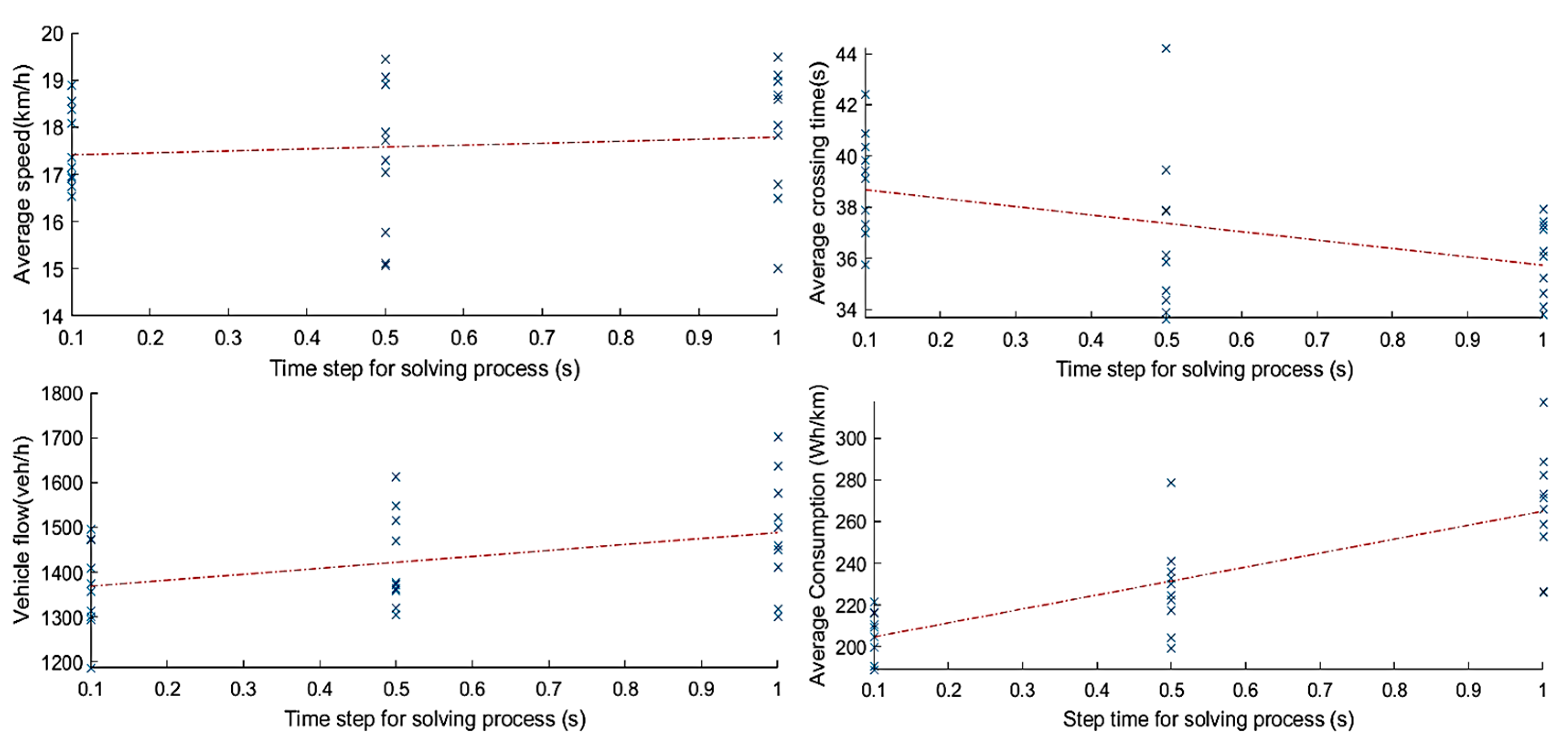
Concerning the time step for the solving process, the paradox is that a time step increase means fewer points acquired on the trajectory, it means that the trajectory is less accurate but also less restricted; thus, smoother. The curvature radius being higher, allowed for max speed respecting the lateral acceleration criteria is also higher, as shown in Figure 10.
As a result, the average speed is increased as it is less restricted by lateral acceleration criteria; thus, resulting in a better vehicle flow through the roundabout. However, higher step time means less smooth and accurate control of the acceleration cycle, high and sudden acceleration could occur more often, and it impacts vehicle consumption.
When it comes to roundabout zoning impact on system performance, the flow increases with the number of zones as the division of the roundabout is more precise, leading to more accuracy, and more vehicles entering the roundabout, as noted in Figure 11.
However, as every zone has a checkpoint, trajectories are more constrained with more zones, leading to lower maximum speed to respect lateral acceleration criteria. Moreover, with more vehicles entering the roundabout, interactions between vehicles are more numerous, increasing re-acceleration phases, and consumption.
As can be seen, the benefits of less accurate step time and the number of zones between entrances results in a smoother trajectory. To obtain these benefits alongside the reduced consumption of a more accurate step time and the increased flow of a higher number of zones, work on the optimization of the initial vehicle path must be performed in order to obtain a smooth trajectory even with a low step time and a high number of zones. However, step time is also limited by the heaviness of calculations as a fast response algorithm is needed.

4.3. Safety and Comfort

How to efficiently cross a roundabout with autonomous vehicles is a key part of the problem, but crossing it safely is the other major issue. To ensure comfort and safety, the impact of three criteria on performance has been evaluated:
-
Admissible lateral acceleration: for driver comfort, the choice is made to limit it to 0.3 g at first, but a higher value of 0.4 g is tolerated according to Schramm et al. [30] and could lead to a higher speed in curves as a speed limitation along the vehicle trajectory come from this comfort criteria using Equation (1).
-
Speed limitation: as previously stated, speed limitation in the roundabout is mainly automatically regulated by the algorithm using lateral acceleration criteria as depicted in Equation (1). However, some areas on the trajectory are less restrictive, and a stringent speed limitation could also be added for safety issues, depending on the area of implantation of the roundabout.
-
Additional safety distance: this is an additional safety feature that can be added to the safety distance induced by zone booking. Set to 0 m in the reference case, additional safety distance could be needed in case of a high number of roundabout zones, and consequently, very accurate booking by vehicles. A trade-off would then have to be found with system performance.
All these criteria have their own effect on roundabout performance. A simulation design matrix allows the evaluation of the impact of all these effects (see Table 5).
When it comes to studying the effect of each safety and comfort parameters some observations could be made:
-
Increasing admissible lateral acceleration by 0.1 g, allows vehicles to go faster inside the roundabout; thus, reducing crossing times and increasing vehicle flow, with a limited impact on consumption. A trade-off is to be made between passenger comfort and high admissible lateral acceleration.
-
Increasing speed limitation by 20 km/h will have the same benefits as increasing maximum admissible lateral acceleration, but on a smaller scale, as speed is mainly limited by an admissible lateral acceleration in curves. However, a 20 km/h increase also has the biggest impact on the increase of consumption with a high acceleration level to reach these higher speeds.
-
Increasing safety distance by 2 m implies slightly less space allocated to every vehicle, slightly reducing their speed; thus, slightly increasing their crossing times. Combined with the fact that fewer vehicles are entering the roundabout, it significantly reduces the overall traffic flow. However, as fewer vehicles are entering the roundabout, in-roundabout interactions also decrease, limiting re-acceleration phases, with a smoother speed profile; thus, reducing average consumption.
The other benefit of the simulation matrix tool is that it allows us to see the absolute value of the combined effect that these parameters can have. Thus:
-
To obtain a big variation in crossing time and vehicle speed, in one sense or another, a speed limitation of 20 km/h variation combined with a safety distance of 2 m variation would be the criteria that would obtain the highest combined effect.
-
To obtain a big variation in overall traffic flow, in one sense or another, a speed limitation of 20 km/h variation combined with an admissible lateral acceleration of 0.1 g variation would be the criteria that would obtain the highest combined effect.
-
To obtain a big variation in average consumption, in one sense or another, the three parameters variate at the same time giving a higher combined effect.
These combined effects are to be considered and added to the variations of the parameter’s initial effects.
In this study, the benefits of increasing admissible lateral performance in terms of speed and crossing times are demonstrated as the best but reaching the limit of 0.4 g defined by Schramm et al. [30] is questionable for comfort issues.
Thus, using the combined effect of speed limitation and safety distance variation, in addition to the proper benefits of increasing speed limitation on crossing times reduction and average speed increase, these values obtained with an increase of admissible lateral acceleration can be matched, without having to increase it.
A good trade-off between roundabout performance and safety and comfort must be found, but in practice, it may depend on each roundabout’s geographical and technical context.

4.4. CBVC Traffic Manager Performance Comparison with SUMO Benchmark Simulator

CBVC has been designed to ensure safety in roundabouts crossed by CAV. In addition to safety, the traffic flow performance of CBVC must be analyzed and compared. To assess the traffic flow performance of the CBVC developed in the scope of this project, a comparison with an existing traffic manager has been performed. A lot of different traffic managers with different functionalities exist. A type of characteristic that differentiates simulators is the level of detail captured by the model. Models are usually categorized as macroscopic, microscopic, and mesoscopic (see Table 6):
  • Macroscopic Models: Characterize traffic as an aggregate flow. Macroscopic models offer computational efficiency, but reduced fidelity because they cannot model the behavior of individual vehicles;
  • Microscopic models: Often include gap acceptance models to characterize a driver’s willingness to enter another stream of traffic or to change lanes. Many microscopic traffic simulators have been developed. A few examples include SUMO, TRANSIMS, CORSIM, PARAMICS, MITSIM, and VISSIM;
  • Mesoscopic models: Lie between macroscopic and microscopic models. They typically model clusters or platoons of vehicles and focus on modeling the interactions between clusters. Examples of mesoscopic models include MATsim, CORFLO/NETFLO, DYNASMART, DYNEMO, and INTEGRATION.
SUMO is a free and open-source traffic simulation suite well suited for this comparison with the CBVC traffic manager [35]. It has been available since 2001 and allows the modeling of intermodal traffic systems—including road vehicles, public transport, and pedestrians. The roundabout in SUMO illustrated in Figure 12 has been built in the same conditions as the roundabout developed in this study. The vehicles arrive randomly in the roundabout and can only cross the road at given positions as is the case for the roundabout studied, the speed of the vehicles is limited to a lateral acceleration of 0.3 g, and priority is given to the vehicles already in the roundabout. The case study was run 100 times to obtain an accurate average performance of the traffic manager. The maximum cross-time, the average cross-time, the duration of the simulation, the average speed, and the flow were taken out of the simulation.
The case study is fixed to a roundabout with four entries, two internal roads, an external radius of thirty meters, and a road width of five meters. The CBVC traffic manager reaches a flow performance of 1424 vehicles per hour whereas SUMOs manager reaches 1188 vehicles per hour. This result confirms that the CBVC performance in terms of traffic flow is acceptable while ensuring safety in the roundabout. This flow performance could be due to the usage of a zoning strategy rather than an absolute priority strategy, to the fact that SUMOs manager can be implemented on every type of network whereas the CBVC developed is completely dedicated to roundabouts. In the same trend, the average cross time and the maximum cross time are smaller using the CBVC manager compared to SUMOs manager (see Table 7).

5. Conclusions

Autonomous vehicles are becoming an increasingly important part of the automotive industry, offering a safer and more efficient alternative for driving on the road. Intersections, such as roundabouts, are an integral part of the world’s road landscape, so it is important to develop technologies that allow these new vehicles to cross roundabouts in a safe way.
During this study, it was decided to implement a V2I strategy; therefore, using a CSU to communicate with the vehicles and manage their arrival in the roundabout, and manage the reservation of the zones from their entry to exit. The behavior of the vehicles is modeled with a bicycle model. Finally, a graphical representation is used to visualize the passage of vehicles through the roundabout.
Numerous simulations have been carried out to analyze the influence of traffic, roundabouts, accuracy, and driver safety parameters. These results can be used in the future to design and regulate intersections for these new connected autonomous vehicles. Above all, these simulations proved that the strategy adopted during this work can manage the traffic in a roundabout safely independently of the geometry of the intersection. However, this study requires some installation and adaptation of the current roundabouts such as an external supervisor i.e., CSU which manages the traffic. Therefore, it is suggested to implement this strategy in roundabouts with a high-risk factor as discussed by Riccardi, M.R. et al. [36].
This study can be improved in the future to approach a more accurate model to improve the performance and safety within the roundabout. It is first possible to use the moving blocks technique already used in the railway industry rather than separating the roundabout into a fixed number of zones. It would also be interesting to add a more representative vehicle dynamics model to obtain a more accurate trajectory; thus, optimizing the blocks to reserve.
Moreover, a formal demonstration of the impossibility of deadlock with the actual strategy but also of the maximum time to pass a roundabout once the first movement is granted could be added.
It would also be interesting to perform an experimental validation of our traffic manager by starting with validations on miniature vehicles. This would be a good way to physically see the possible collisions and the traffic fluidity while saving time and money compared to validations on real vehicles.

Author Contributions

Conceptualization, C.V., N.P., B.O. and B.R.; methodology, S.C. and B.R.; software, C.V., N.P., B.O. and B.R.; validation, O.E.G.-M., S.C. and C.V.; investigation, B.O.; data curation, O.E.G.-M., S.C., C.V. and N.P.; writing—original draft, O.E.G.-M., S.C., C.V., N.P., B.O. and B.R.; writing—review & editing, O.E.G.-M.; supervision, O.E.G.-M. and S.C. All authors have read and agreed to the published version of the manuscript.

Funding

This research received no external funding.

Informed Consent Statement

Not applicable.

Data Availability Statement

Not applicable.

Conflicts of Interest

The authors declare no conflict of interest.

Nomenclature

ParametersDefinitions
a y ,   m a x Longitudinal vehicle acceleration [ m · s 2 ]
CConsumption [ Wh · km 1 ]
C r r Rolling resistance ratio [ ]
F t o t Total sum of forces [ N ]
g Gravitational constant [ N · m 2 · kg 2 ]
NWheel speed [ rad · s 1 ]
P Vehicle power [ W ]
R w Radius of a wheel [ m ]
R Reducer ratio [ ]
T Vehicle torque [ Nm ]
V Vehicle speed [ m · s 1 }
ρ Air density [ kg · m 3 ]

References

  1. Boualam, O.; Borsos, A.; Koren, C.; Nagy, V. Impact of Autonomous Vehicles on Roundabout Capacity. Sustainability 2022, 14, 2203. [Google Scholar] [CrossRef]
  2. Anagnostopoulos, A.; Kehagia, F. CAVs and roundabouts: Research on traffic impacts and design elements. Transp. Res. Procedia 2020, 49, 83–94. [Google Scholar] [CrossRef]
  3. Erikson, J.; Svensson, L. Tuning for Ride Quality in Autonomous Vehicle; Uppsala Universitet, Teknisk—Naturvetenskaplig Fakultet UTH-Enheten: Uppsala, Sweden, 2015. [Google Scholar]
  4. Alphand, F.; Noelle, U.; Guichet, B. Roundabouts and safety—State of the art in France. In Intersections without Traffic Signals (II); Springer: Berlin/Heidelberg, Germany, 1991; pp. 107–125. ISBN 3-540-54180-2. [Google Scholar]
  5. Bill, A.; Khan, G. Safety evaluation of Wisconsin roundabouts. In Proceedings of the 4th International Roundabout Conference, Seattle, WA, USA, 16–18 April 2014. [Google Scholar]
  6. Elvik, R. Effects on Road Safety of Converting Intersections to Roundabouts: Review of Evidence from Non-U.S. Studies. Transp. Res. Rec. 2003, 1847, 1–10. [Google Scholar] [CrossRef]
  7. Brilon, W.; Stuwe, B. Capacity and design of traffic circles in Germany. Transp. Res. Rec. 1993, 1398, 61–67. [Google Scholar]
  8. Wang, W.; Lin, H.; Wang, J. CNN based lane detection with instance segmentation in edge-cloud computing. J. Cloud Comput. Adv. Syst. Appl. 2020, 9, 27. [Google Scholar] [CrossRef]
  9. Xu, X.; Zhang, X.; Khan, M.; Dou, W.; Xue, S.; Yu, S. A balanced virtual machine scheduling method for energy-performance trade-offs in cyber-physical cloud systems. Future Gener. Comput. Syst. 2020, 105, 789–799. [Google Scholar] [CrossRef]
  10. García Cuenca, L.; Puertas, E.; Fernandez Andrés, J.; Nourdine, A. Autonomous driving in roundabout maneuvers using reinforcement learning with Q-learning. Electronics 2019, 8, 1536. [Google Scholar] [CrossRef] [Green Version]
  11. Wong, K.I.; Wong, S.C. Evaluating the capacity and performance of roundabouts: A review of research. Transp. Rev. 2018, 38, 1–26. [Google Scholar]
  12. Wu, N.; Rouphail, N.M. Microscopic traffic flow modeling at roundabouts: A review. Transp. Res. Part C Emerg. Technol. 2012, 25, 150–166. [Google Scholar]
  13. Tian, Z.; Yang, Q. A comprehensive review of roundabout capacity analysis methods. J. Transp. Eng. Part A Syst. 2016, 142, 04016022. [Google Scholar]
  14. Hossain, M.A.; Rahman, M.S. Performance evaluation of roundabouts considering mixed traffic conditions. Transp. Res. Part A Policy Pract. 2015, 71, 162–176. [Google Scholar]
  15. Haque, M.M.; Hossain, M.A.; Rakha, H.A. Analyzing the effects of autonomous vehicles on roundabout operations. J. Intell. Transp. Syst. 2019, 23, 316–328. [Google Scholar]
  16. El Ganaoui-Mourlan, O.; Camp, S.; Hannagan, T.; Arora, V.; De Neuville, M.; Kousournas, V.A. Path Planning for Autonomous Platoon Formation. Sustainability 2021, 13, 4668. [Google Scholar] [CrossRef]
  17. Lakshmanan, V.; Sciarretta, A.; El Ganaoui-Mourlan, O. Cooperative Eco-Driving of Electric Vehicle Platoons for Energy Efficiency and String Stability. IFAC-PapersOnLine 2021, 54, 33–139. [Google Scholar] [CrossRef]
  18. Lakshmanan, V.K.; Sciarretta, A.; El-Ganaoui Mourlan, O. Cooperative Levels in Eco-Driving of Electric Vehicle Platoons. In Proceedings of the IEEE International Intelligent Transportation Systems Conference (ITSC), Indianapolis, IN, USA, 19–22 September 2021; pp. 1163–1170. [Google Scholar] [CrossRef]
  19. ISO 26262-1:2018; Road Vehicles—Functional Safety—Part 1: Vocabulary. ISO: Geneva, Switzerland, 2018. Available online: https://www.iso.org/standard/68383.html (accessed on 10 April 2023).
  20. SIST EN 50657:2017; Railway Applications—Rolling Stock Applications—Software on Board of Rolling Stock. Slovenian Institute for Standardization: Ljubljana, Slovenia, 2017.
  21. Los, J.; Schulte, F.; Spaan, M.T.J.; Negenborn, R.R. The value of information sharing for platform-based collaborative vehicle routing. Transp. Res. Part E Logist. Transp. Rev. 2020, 141, 102011. [Google Scholar] [CrossRef]
  22. Takashige, T. Signaling system for safe railway transport. Jpn. Railw. Transp. Rev. 1999, 21, 44–50. [Google Scholar]
  23. Bevrani, K.; Chung, E.; Teo, P. The Space-Based Car-Following Model: Development and Application for Managed Motorway System Safety Evaluation. Future Transp. 2021, 1, 443–465. [Google Scholar] [CrossRef]
  24. Takeuchi, H.; Goodman, C.J.; Sone, S. Moving block signaling dynamics: Performance measures and re-starting queued electric trains. IEE Proc. Electr. Power Appl. 2003, 150, 483–492. [Google Scholar] [CrossRef]
  25. Ren, H.; Shim, T.; Ryu, J.; Chen, S. Development of Effective Bicycle Model for Wide Ranges of Vehicle Operations; SAE Technical Paper Series; SAE: Warrendale, PA, USA, 2014; Available online: https://www.researchgate.net/publication/286912996_Development_of_Effective_Bicycle_Model_for_Wide_Ranges_of_Vehicle_Operations (accessed on 4 April 2023).
  26. Polack, P.; Altché, F.; d’Andréa-Novel, B.; de La Fortelle, A. The kinematic bicycle model: A consistent model for planning feasible trajectories for autonomous vehicles? In Proceedings of the 2017 IEEE Intelligent Vehicles Symposium, Los Angeles, CA, USA, 11–14 June 2017; Available online: https://www.researchgate.net/publication/318810853_The_kinematic_bicycle_model_A_consistent_model_for_planning_feasible_trajectories_for_autonomous_vehicles (accessed on 24 March 2023).
  27. Dong, C.; Wang, H.; Li, Y.; Liu, Y.; Chen, Q. Economic comparison between vehicle-to vehicle (V2V) and vehicle-to-infrastructure (V2I) at freeway on-ramps based on microscopic simulations. IET Intell. Transp. Syst. 2019, 13, 1726–1735. [Google Scholar] [CrossRef]
  28. Cho, W.; Kim, S.I.; Choi, H.K.; Oh, H.S.; Kwak, D.Y. Performance evaluation of V2V/V2I communications: The effect of midamble insertion. In Proceedings of the 2009 1st International Conference on Wireless Communication, Vehicular Technology, Information Theory and Aerospace & Electronic Systems Technology, Aalborg, Denmark, 17–20 May 2009; pp. 793–797. [Google Scholar] [CrossRef]
  29. Code de la Route. Available online: https://codedelaroute.io/blog/clignotant-rond-point/ (accessed on 20 June 2022).
  30. Schramm, D.; Hiller, M.; Bardini, R. Vehicle Dynamics: Modeling and Simulation; Springer: Berlin/Heidelberg, Germany, 2018. [Google Scholar]
  31. Rentsch, T. Object oriented programming. ACM Sigplan Not. 1982, 17, 51–57. [Google Scholar] [CrossRef]
  32. Les Carrefours Giratoires Urbains. Available online: https://www.creuse.gouv.fr/contenu/telechargement/4937/35507/file/Giratoires_urbains.pdf (accessed on 10 April 2023).
  33. Demir, H.G.; Demir, Y.K. A Comparison of Traffic Flow Performance of Roundabouts and Signalized Intersections: A Case Study in Nigde; Department of Civil Engineering, Faculty of Engineering, Niğde Ömer Halisdemir University (NOHU): Nigde, Turkey, 2020. [Google Scholar]
  34. Martin-Gasulla, M.; Elefteriadou, L. Single-Lane Roundabout Manager under Fully Automated Vehicle Environment. Transp. Res. Rec. 2019, 2673, 439–449. [Google Scholar] [CrossRef]
  35. UMO User Documentation. Available online: https://sumo.dlr.de/docs/index.html (accessed on 10 April 2023).
  36. Riccardi, M.R.; Augeri, M.G.; Galante, F.; Mauriello, F.; Nicolosi, V.; Montella, A. Safety Index for evaluation of urban roundabouts. Accid. Anal. Prev. 2022, 178, 106858. [Google Scholar] [CrossRef]
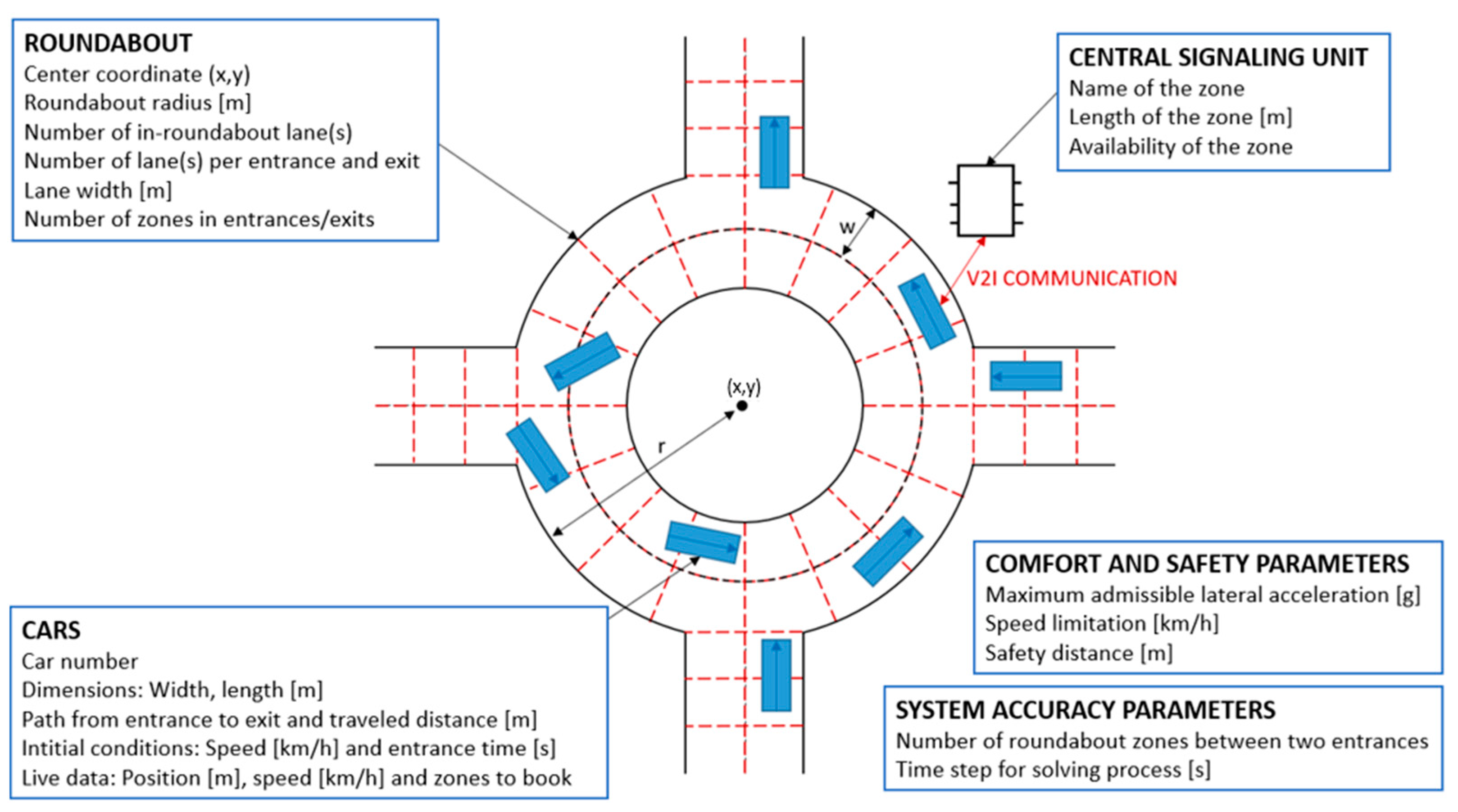
Figure 1. System overview.
Sustainability 15 09247 g001
Figure 2. Roundabout possible trajectories [29].
Sustainability 15 09247 g002
Figure 3. CBVC algorithm architecture.
Sustainability 15 09247 g003
Figure 4. Solver iterative process.
Sustainability 15 09247 g004
Figure 5. Driving Scenario Designer interface. The color rectangles are the vehicles circulating in the roundabouts. The white dots are points used to build the roundabout.
Sustainability 15 09247 g005
Figure 6. Average vehicle speed, crossing times, flow, and consumption depending on the number of vehicles. The crosses are points recorded during simulations whereas the red line is the linear trend of the recorded points.
Sustainability 15 09247 g006
Figure 7. Deadlock and overload difference inside the roundabout depending on right-of-way. The color rectangles are the vehicles circulating in the roundabouts. The white dots are points used to build the roundabout.
Sustainability 15 09247 g007
Figure 8. Reduced roundabout (left); and Increased roundabout (right). The color rectangles are the vehicles circulating in the roundabouts. The white dots are points used to build the roundabout.
Sustainability 15 09247 g008
Figure 9. Average vehicle speed, crossing times, flow, and consumption depending on the roundabout radius. The crosses are points recorded during simulations whereas the red line is the linear trend of the recorded points.
Sustainability 15 09247 g009
Figure 10. Average vehicle speed, crossing times, flow, and consumption depending on the time step for the solving process. The crosses are points recorded during simulations whereas the red line is the linear trend of the recorded points.
Sustainability 15 09247 g010
Figure 11. Average vehicle speed, crossing times, flow, and consumption depending on the number of zones between entrances. The crosses are points recorded during simulations whereas the red line is the linear trend of the recorded points.
Sustainability 15 09247 g011
Figure 12. Illustration of the SUMO simulation interface. The blue rectangles are the vehicles circulating in the roundabout.
Sustainability 15 09247 g012
Table 1. Vehicle data for consumption estimation.
ParametersDefinitionsValues
MvehicleMass of the Vehicle [kg]1200
SxCxLongitudinal area of the vehicle [m2], Longitudinal aerodynamic coefficient of the vehicle [-]0.7
Crr Rolling resistance ratio [-]7.5
Rw Radius of a wheel [m] 0.3
RReducer ratio [-]10
ηtransmission Transmission efficiency [-]0.95
ηEM Electric motor efficiency [-]0.8
Table 2. Reference parameters.
ParametersValues
Number of vehicles60
Number of roundabout lanes2
Number of entry/exit lane(s) [entry]1
Roundabout radius [m]30
Solving process time step [s]0.5
Number of roundabout zones [/entry]6
Admissible lateral acceleration [g]0.3
Speed limitation [km/h]30
Safety distance [m]0
Table 3. Average performance depending on the chosen right-of-way.
Right of WayFirst Arrived, First ServedIn-Roundabout Priority
Average crossing time55.837.4 (−33.0%)
Average speed [km/h]12.418.7 (+50.8%)
Average vehicle flow [veh/h]1318.61423.8 (+8.0%)
Average consumption [Wh/km]255.6216.3 (−15.4%)
Table 4. Average performance depending on the number of roundabout lanes.
CasesReference
(2 in-Roundabout Lanes, 1 Lane per Entrance/Exit)
Reduced Configuration
(1 in-Roundabout Lane, 1 Lane per Entrance/Exit)
Increased Configuration
(2 in-Roundabout Lanes, 2 Lanes per Entrance/Exit)
Average crossing time [s]37.295.1 (+155.6%)38.0 (+2.2%)
Average speed [km/h]18.48.9 (−51.6%)17.3 (−6.0%)
Average vh. flow [veh/h]1407.2782.7 (−44.4%)1637.6 (+16.4%)
Average cons. [Wh/km]224.8338.6 (+50.6%)173.9 (−22.6%)
Table 5. Simulation design matrix evaluating comfort and safety criteria. Legend: Best case; Worst case.
ConditionsResults
Lateral Acceleration Limit [g]Maximum Speed Limit [km/h]Minimum Safety Distance [m]Average Crossing Time [s]Average Speed [km/h]Average Flow [veh/h]Average Consumption [kWh/km]
Case 10.450232.619.61535.2251.7
Case 20.450033.219.31557.3274.7
Case 30.430236.018.71424.9200.7
Case 40.430034.119.31502.9216.9
Case 50.350235.918.31417.0267.8
Case 60.350037.217.71469.5248.9
Case 70.330238.217.41365.5215.0
Case 80.330035.818.21457.7236.0
Table 6. Traffic Simulators Comparison.
SimulatorOpen SourceTypeNetwork and Flow ConstructionCommunity and Documentation
SUMOYesMicroscopicEasyVery good
MATSimYesMesoscopicMediumGood
TRANSIMSYesMicroscopicMediumLow
MITSIMLab/SIMMOBLITYYesMicro/MessoMediumVery low
Table 7. Average performance depending on the chosen solver.
Average PerformanceSUMOCBVC
Vehicle flow [vehicle/h]11881540 (+23%)
Average crossing time [s]54.335.7 (−34%)
Maximum crossing time [s]94.674.3 (−21%)
Disclaimer/Publisher’s Note: The statements, opinions and data contained in all publications are solely those of the individual author(s) and contributor(s) and not of MDPI and/or the editor(s). MDPI and/or the editor(s) disclaim responsibility for any injury to people or property resulting from any ideas, methods, instructions or products referred to in the content.