Article

On-Site Experimental Study on Low-Temperature Deep Waste Heat Recovery of Actual Flue Gas from the Reformer of Hydrogen Production

1
School of Environmental and Energy Engineering, Institute of Waste Energy Utilization and Energy Saving, Beijing University of Civil Engineering and Architecture, Beijing 100044, China
2
Department of Chemical Engineering, Dalian University of Technology, Dalian 116023, China
3
Shandong Chambroad Petrochemicals Co., Ltd., Binzhou 256500, China
*
Author to whom correspondence should be addressed.
Sustainability 2023, 15(12), 9495; https://doi.org/10.3390/su15129495
Submission received: 17 April 2023 / Revised: 24 May 2023 / Accepted: 12 June 2023 / Published: 13 June 2023

Abstract

:
Improving the energy-saving efficiency of flue gas deep waste heat and reducing the emission of carbon dioxide and other pollutants have been two issues that need to be paid attention to in petrochemical heating furnaces. A hydrogen production reformer with high energy consumption and high carbon emissions in the petroleum refining process affects the thermal and productive efficiency of the hydrogen production, amounts of heat from flue gas are wasted with the exhausted corrosive gas of the reformer, and latent heat is not recovered. To recover the sensible and latent heat from the exhausted gas, a new anti-corrosion, high-efficiency, and low-pressure-drop flue gas condensing heat exchanger (FGCHE) with low consumption and pressure drop was developed. The energy-saving performance was evaluated through on-site measurements and theoretical analysis. The results show that the exhausted gas temperature was reduced from 161.3~175.9 °C to 33.9~38.9 °C after using the new FGCHE to recover waste heat. The energy-saving efficiency and the utilization ratio of flue gas waste heat were 12~16.1% and 74~81.9%, respectively. The latent heat accounted for 41.3~48.1% of the total recovered heat. The exergy efficiency and the total thermal efficiency of the reformer reached 73~86.8% and 95.2~96.6%, respectively. The condensation in the flue gas reduced pollutant emissions (SO2 and NOx). This paper provides a practical application reference for the technology development of waste heat recovery and the application of an FGCHE for petrochemical heating furnaces.

1. Introduction

In 2022, China’s total energy consumption was 5.41 billion tons of standard coal, of which industrial energy consumption accounted for about 65% [1]. For industry, around 42% of the total primary energy consumption as waste heat is directly emitted in different forms [2]. Industrial waste heat recovery and hydrogen production are the most promising methods to reduce carbon emissions [3] and realize carbon peaking and carbon neutrality goals. Hydrogen production methods mainly contain hydrocarbon conversion, reforming by-products, and refinery hydrogen-rich gas purification [4,5]. Hydrocarbon conversion to the reformer of hydrogen production plays a main role in hydrogen production, accounting for 80% of total hydrogen production [6]. The reformer determines the amount of hydrogen production and provides raw materials and fuel for the refining process, as shown in Figure 1, while flue gas exhausted from the hydrogen production reformer (HPR) with temperatures of 150~250 °C is exhausted, which is 17~22% of the total heat of fuel consumption. Exhausted waste heat recovery is beneficial to saving energy [7,8], efficiency improvement [9,10], water conservation [11,12], pollution reduction, and carbon reduction [13,14,15].
Heat exchangers (e.g., heat pipe, air preheater, etc.), the most widely used in waste heat recovery technology, significantly affect the amount of heat transfer and thermal efficiency. Therefore, some researchers have studied the heat transfer characteristics of heat exchangers. Table 1 presents the application of different heat exchangers for coal, oil, and natural gas heating furnaces to recover waste heat from flue gas. As shown in Table 1, coal [16,17], fuel oil [18], and gas [19,20,21] heating furnaces have added heat exchangers to recover sensible heat of flue gas, of which the outlet temperature drops to 60~203 °C (higher than the acid dew point temperature). The flue gas contains corrosive gas such as SOx and NOx [22,23]. Hence, the low-temperature (lower than the flue gas water dew point temperature) flue gas deep waste heat recovery of refinery heating furnaces is a technical challenge in the petrochemical industry, while for natural gas boilers, the corrosiveness of flue gas is weak. The water dew point temperature of flue gas from natural gas boilers is generally below 57 °C [24]. The exhaust gas temperature of natural gas boilers can be reduced to 25.7~57 °C lower than the water dew point temperature [25,26,27,28], and the sensible and latent heat of flue gas is deeply recovered. However, the latent heat recovery from the HPR of a petroleum refining system has not been reported and there are no projects implemented or on-site measurements. For fuel gas boilers or furnaces, the latent heat of flue gas accounts for more than 10% of the fuel gas input heat [29]. If the latent heat is deeply recovered, the thermal efficiency of the energy-using system can be significantly improved [30]. The flue gas condensate is precipitated in the process of flue gas condensation and recovered after being treated, reducing the mist emission [31]. In addition, the flue gas condensate also absorbs pollutants such as NOx and SO2 in the exhausted gas [32], which purifies the flue gas, reduces pollutant emissions, and improves the atmospheric quality. Hence, latent heat recovery from flue gas plays an important role in saving energy, water conservation, and emission reduction.
There are many ways to evaluate the thermal performance of waste heat recovery systems. Energy saving and exergy efficiency are commonly used [33,34]. The energy-saving efficiency of flue gas waste heat is analyzed based on the first law of thermodynamics, while the exergy efficiency is analyzed by combining the first and second laws of thermodynamics. Li et al. [35] conducted an energy and exergy analysis of waste heat recovery from a cogeneration plant and pointed out the optimization direction using thermodynamic analysis. Hernandez et al. [36] adopted exergy to evaluate material efficiency and energy efficiency. Hamedi et al. [37] applied exergy analysis to study the contributions of the olefin plant to total exergy destruction. Utlu et al. [38] employed energy and exergy analysis to obtain the efficiency and heat recovery potential of Turkish industrial sectors. Shariati et al. [39] carried out an exergy analysis on the waste heat recovery section (including the feed preheater part, the pre-reformer reactor, and the reformer reactor) about the sensible heat of flue gas from the steam-natural gas reformer, and the exergy efficiency reached 0.58. However, there are few studies that have investigated the exergy efficiency of the flue gas condensing heat exchanger (FGCHE) used in the HPR.
To fill the above-mentioned gap, the FGCHE is used to recover the sensible and latent waste heat. The temperature of exhausted gas is reduced to below the flue gas water dew point temperature, and then the sensible and latent heat of low-temperature flue gas and the condensed water can be recovered. Meanwhile, the acid-condensed water corrodes the heat exchanger and increases equipment consumption. Low heat-transferred-temperature differences lead to a higher area of the heat exchanger. Additionally, a new anti-corrosion, high-efficiency, and low-pressure-drop FGCHE was developed and applied in the HPR. Meanwhile, the energy-saving performance of the FGCHE was measured on-site. The results of this paper can offer a design reference for similar furnaces or reformers to achieve deep utilization, energy savings, efficiency improvements, and carbon and pollution reduction for low-temperature waste heat recovery. For petroleum refining furnaces with high exhausted gas temperatures, the sensible and latent heat in the flue gas waste heat can be recovered by installing an anti-corrosive FGCHE, saving primary energy and improving the energy utilization ratio of the refining enterprises. Hence, it also provides a feasible solution for low-temperature flue gas deep waste heat to recover the latent heat and condensed water from the flue gas of the petrochemical heating furnaces.
The structure of the following section is as follows. In Section 2, the low-temperature deep waste heat recovery system (LT-DWHRS) for the reformer is designed, and the potential of the low-temperature deep recovery system of waste heat is analyzed; In Section 3, the on-site measurement method and data analysis basis are given; In Section 4, the energy saving performance and exergy efficiency of the FGCHE under different operating conditions are discussed. Additionally, the socio-economic and environmental benefits of the FGCHE are analyzed.

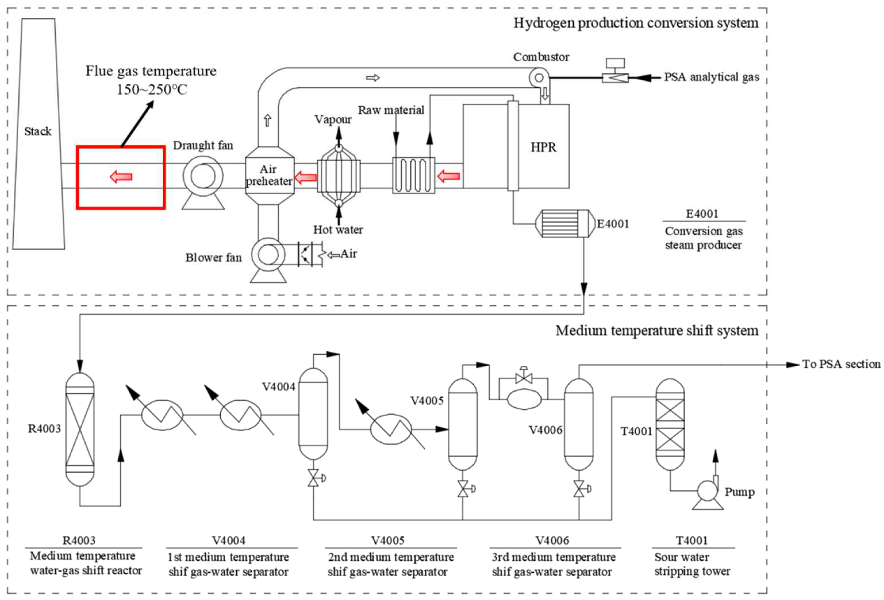
2. System Description

2.1. Low-Temperature Deep Waste Heat Recovery System in a Reformer

The reformer of a 5000 Nm3/h hydrogen production unit was reformed for the LT-DWHRS, as shown in Figure 2. Based on the operating parameters of the reformer and the heat demand of the refinery, the anti-corrosion, high-efficiency, and low-pressure-drop FGCHE was applied at the rear of the air preheater (AP) and draught fan to heat the low-temperature demineralized water, which was used as water replenishment for a self-contained power plant in a petrochemical enterprise.
Pressure swing adsorption (PSA) gas is mainly used for fuel gas combustion in HPRs. The composition and calorific value of the PSA gas are shown in Table 2. The PSA gas is burned in the HPR to heat the raw material, and produces high-temperature flue gas, which successively passes through the raw material gas preheating section (RMGP), the steam generation section (SGS), the air preheater (AP), the draught fan, the FGCHE, and the stack. The PSA gas consumption, temperature, and components of flue gas after AP are shown in Table 3.

2.2. Flue Gas Condensing Heat Exchanger and Its Energy-Saving Potential

The novel anti-corrosion, high-efficiency, and low-pressure-drop FGCHE determines the recovery of flue gas waste heat. The surface of the fin-and-tube for the condensing heat exchanger was modified by anti-corrosion coating, which can prevent corrosion at the dew point of flue gas. The counter current pattern was applied in the condensing heat exchanger, where the flow direction of the flue gas in the FGCHE is from top to bottom, and the cooling water flows from bottom to top. This pattern is conducive to improving the heat exchange efficiency of the heat exchanger. During the heating process, the cooling water releases gases that flow upwards along with the cooling water and are discharged by the exhaust valve at the highest position. The condensed water is released and collected in the tank after the flue gas cools lower than the dew point temperature. Meanwhile, the condensed water flows in the same direction as the flue gas, which drives the flue gas condensate’s timely discharge and improves the heat transfer performance of the FGCHE. The condensed water can be used as supply water after treatment. The exhausted gas pressure of the HPR system is about 100 Pa. The outlet pressure of exhausted gas can overcome the flue gas pressure drop of the FGCHE (less than 30 Pa) without extra power consumption of the draught fan.
Table 4 presents the energy-saving and carbon-reducing potential analysis of the FGCHE. Under the design conditions of the FGCHE, the PSA gas volume flow rate, excess air coefficient, and flue gas volume flow rate were 2354 Nm3/h, 1.3, and 8330 Nm3/h, respectively. When the exhausted gas temperature was reduced from 170 °C to 40 °C, the energy saving efficiency, waste heat recovery amount, and utilization ratio of the flue gas were 13.8% (HHV), 902 kW, and 64.4%, respectively. The 25 m3/h low-temperature demineralized water as cooling water was heated from 25 °C to 56 °C, and the flue gas condensed water flow rate was 14.9 t/d. When the annual operation time of the reformer was 8000 h, the annual PSA gas volume flue rate can be saved by 3.083 million Nm3/a, with the CO2 emissions reduced by 4278 t/a.

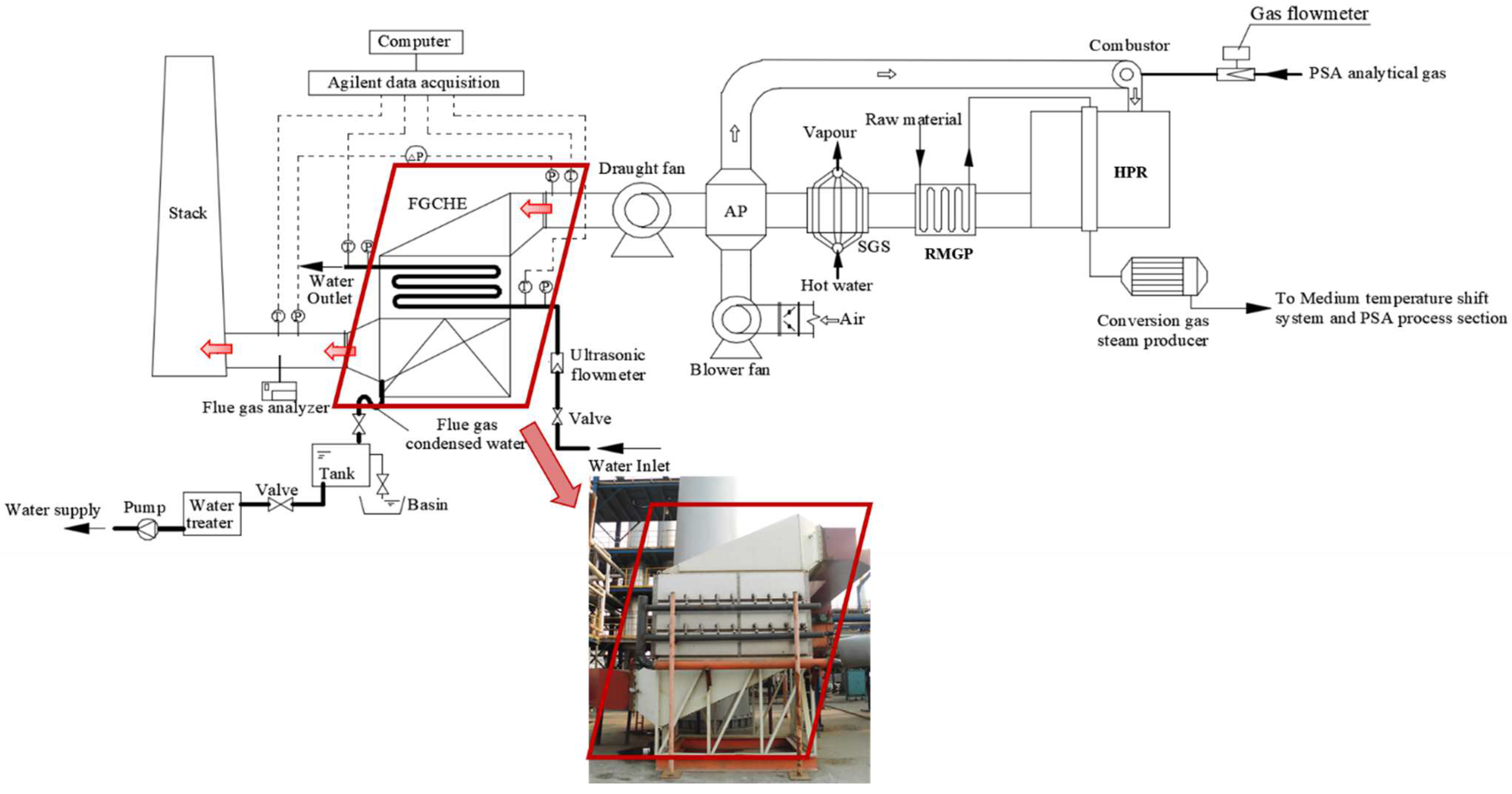
3. On-Site Measurement Method

3.1. On-Site Measurement System and Method

The LT-DWHRS was located in Shandong Chambroad Petrochemical Plant. The detection system of the LT-DWHRS comprised PSA gas, flue gas, and cooling water, as shown in Figure 2.
The PSA gas flow rate, temperature, and pressure were measured by the gas flow meter. The flue gas temperatures were detected by T-type armored thermocouples, and the water temperatures were detected by Pt100-type platinum resistances, which were connected to the Agilent. The data cables were used to transmit the data collected by Agilent to the computer. The flue gas flow pressure drop of the FGCHE was read via a digital micromanometer. The flue gas components were detected using a flue gas analyzer. The cooling water flow rate and pressure were detected with ultrasonic flowmeter and pressure gauges, respectively. Table 5 presents the instruments and the accuracy of the experimental system. Among the testing instruments listed in Table 5, most of the on-site instruments are shown in Figure 2, except for the temperature and humidity recorder, electronic scale, stopwatch, and portable PH tester, which were portable and carried during the on-site tests. The operating parameters of the LT-DWHRS were collected every five minutes, and the detection time was not less than 2 h.
The average temperature of the flue gas was calculated using Equation (1) [40]
t f = i = 1 n t f , i A i N A i = i = 1 n t f , i N
where tf and tf,i are the average and local measuring temperatures of flue gas; Ai is the equivalent area; and N is the measuring number.

3.2. Data Analysis

The fuel gas calorific capacity based on the higher heating value is given by [41]
Q g = H G g
where H and Gg are the higher heating value and volume flow rate of fuel gas, respectively.
Based on the dry flue gas mass flow rate and the flue gas enthalpy difference between the flue gas inlet and standard ambient temperatures, the exhausted heat amount of the HPR is given by
Q eh = m f ( h f , in h am )
where hf,in and mf are the inlet enthalpy and mass flow rate of dry flue gas; ham is the flue gas enthalpy value at standard ambient temperature (20 °C).
The exhausted gas heat loss of the HPR is given by [42]
q 2 = Q eh Q g
where Qeh is the exhausted heat amount and Qg is the fuel gas calorific capacity.
Based on the heat balance theory [41], the thermal efficiency of the reformer was calculated as
η 1 = 100 ( q 2 + q 3 + q 4 + q 5 + q 6 )
where q2, q3, q4, q5, and q6 are heat loss of exhausted gas, heat loss of unburned fuel gas, heat loss of unburned solid, heat dissipation loss, and other heat loss, respectively.
The total thermal efficiency of the reformer system after adding the FGCHE was calculated by
η t = η 1 + η
where η is the energy-saving efficiency of the FGCHE.
According to the inversing balance calculation method, the heat amount released by flue gas can be calculated according to flue gas heat release [42]:
Q f = m f ( h f , in h f , out ) m cw h cw
where hf,out and hcw are the flue gas outlet enthalpy and flue gas condensed water enthalpy; mcw is the flue gas condensed water flow rate.
The flue gas condensed water flow rate was calculated as
m cw = m f × ( d f , in d f , out ) 1000
where df,out and df,in are the flue gas outlet and inlet moisture content, respectively.
Releasing heat amount of flue gas includes sensible heat and latent heat. The sensible heat amount of flue gas can be calculated using
Q f , s = c p , f   ρ f   V f   G   ( t f , in t f , out )
where cp,f is the specific heat capacity of flue gas; ρ is the flue gas density under standard conditions; Vf is flue gas volume per unit of fuel gas; and tf,in and tf,out are flue gas outlet and inlet temperature, respectively.
The latent heat amount of flue gas can be calculated as
Q f , l = Q f Q f , s
According to the positive balance calculation method, the heat absorption amount of cooling water can be obtained using Equation (11) [40]:
Q w = m w h w , out h w , in = m w c p , w t w , out t w , in
where mw is the mass flow rate of cooling water; hw,out and hw,in are the outlet and inlet enthalpies of cooling water; and tw,out and tw,in are the outlet and inlet temperatures of cooling water.
The errors between the water-side and flue-gas-side heat balance calculated using Equation (12) were less than 5%.
χ = Q w Q f Q f × 100 %
Flue gas waste heat recovery amount can be calculated as [43]
Q h = Q w + Q f 2
where Qh is the flue gas waste heat recovery amount.
The utilization ratio of flue gas waste heat of the FGCHE is given by [44]
η h = Q h Q eh
The energy-saving efficiency of the FGCHE is given by [44]
η = Q h Q g
From the perspective of energy conversion and utilization, the exergy efficiency based on the second law of thermodynamics is often one of the important indicators for evaluating the performance of heat exchangers. The exergy efficiency of the FGCHE was calculated using [45]
η ex = Δ E w Δ E f = m w h w , out h w , in m w T 0 S w , out S w , in m f h f , out h f , in m f T 0 S f , out S f , in
Herein, ΔEf and ΔEw denote the exergy difference of flue gas and cooling water; T0 is the ambient temperature (293.15 K); Sf,in, Sf,out, and Sw,in, Sw,out are the inlet- and outlet-specific entropy of flue gas and cooling water.
The dew point of flue gas from the HPR was calculated as [46]
lg P H 2 O = a b t d + c
where td and PH2O are the dew point temperature and water vapor partial pressure of flue gas; a, b, and c are the Antoine constants for water vapor pressure.
The dehumidification rate of flue gas at the outlet of the FGCHE was calculated as
ψ = d f , in d f , out d f , in
Based on the annual PSA gas saving amount and the average concentrations of CO2, NOx, and SO2 emissions from the flue gas of the HPR, the CO2, NOx, and SO2 emission reductions of the LT-DWHRS are expressed in Equation (19)–(21), respectively.
E CO 2 = G sg · ε CO 2
E NO x = G sg · ε NO x
E SO 2 = G sg · ε SO 2
where ECO2, ENOx, and ESO2 are the total emissions of CO2, NOx, and SO2 per year depending on variant, respectively; Gsg is the annual saving amount of PSA gas; and εCO2, εNOx, and εSO2 are PSA gas factors for CO2, NOx, and SO2 emissions (εCO2 = 1.387, εNOx = 1.586 × 10⁻⁴, εSO2 = 2.57 × 10⁻⁶), respectively.
The annual saving amount of PSA gas is
G sg = G av T ar η
where Gav is the average volume flow rate of fuel gas and Tar is the annual running time.
The payback period was evaluated using [47]
PBP = IC ANCF
where PBP, IC, and ANCF are the payback period, the investment cost (including materials and manufacturing costs of the heat exchanger), and the annual net capital flow.

3.3. Uncertainty Analysis

Experimental data measurement were divided into direct measurement and indirect measurement. The former was directly measured with instruments, including the flow rate and temperature of PSA gas and cooling water, condensed water flow rate, and pressure drop of flue gas, etc. The type and accuracy of those instruments are presented in Table 5. Indirect measurement was calculated based on direct measurement values, including exhausted gas waste heat and its recovery amount, utilization ratio, energy saving, and exergy efficiency, etc. According to the uncertainty transitive relations [48] as shown in Equations (24) and (25), the relative uncertainties can be calculated, which depend on both the accuracy of the measuring instruments and testing conditions. The relative uncertainties of Qeh, q2, Qh, ηh, η, ηex, and ψ are 3.16%, 3.5%, 1.05%, 3.33%, 1.83%, 3.66%, and 1.51%, respectively.
Δ y = y x 1 Δ x 1 2 + y x 2 Δ x 2 2 + + y x n Δ x n 2
e = Δ y y × 100 %

4. Results and Discussion

The LT-DWHRS was measured, and the energy-saving performance of the FGCHE under actual operating conditions was obtained.

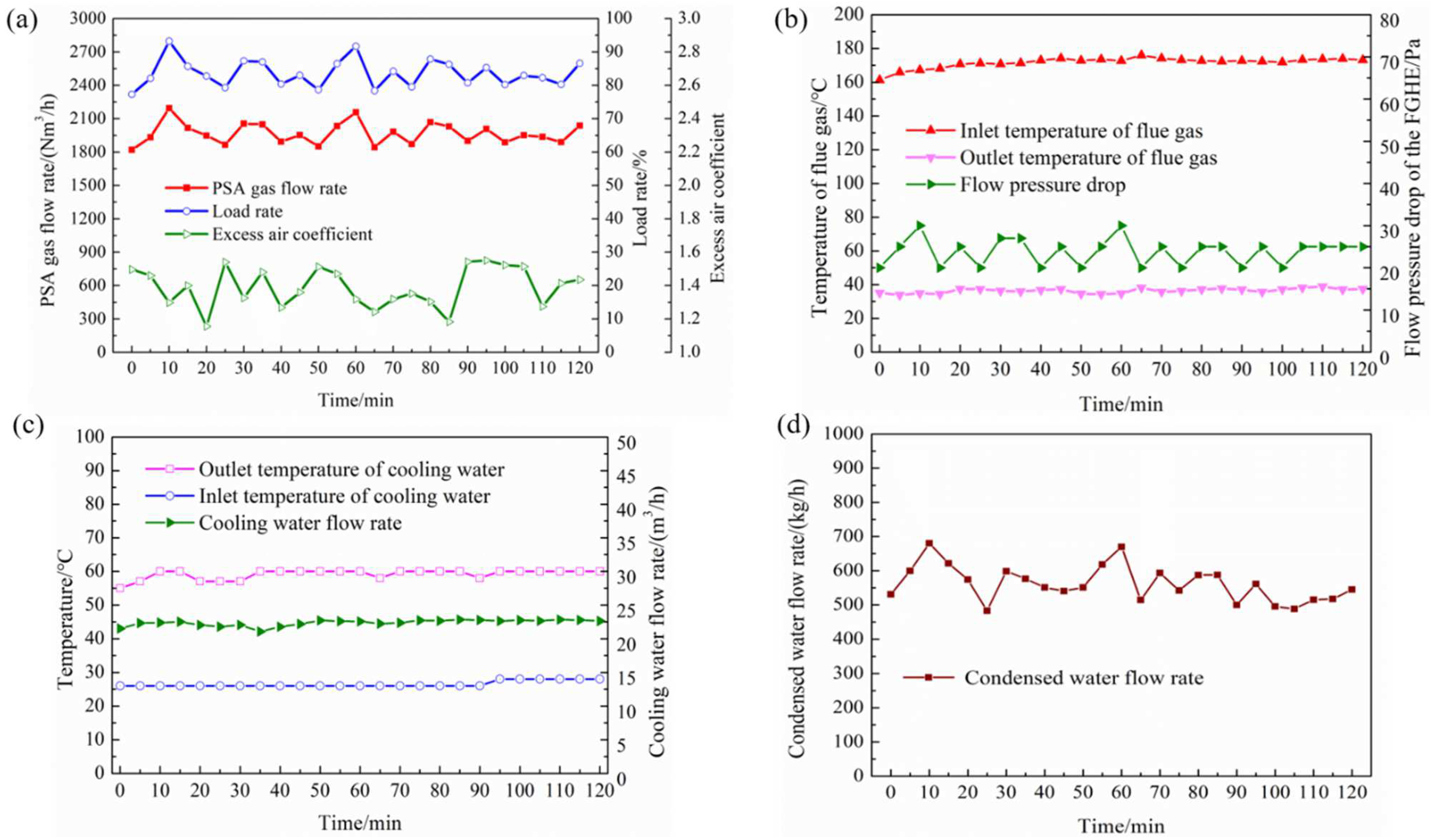
4.1. Operating Parameters of the LT-DWHRS

As shown in Figure 3a, the PSA gas flow rate of the HPR was 1820~2195 Nm3/h, and the average PSA gas flow rate was 1967.6 Nm3/h. The load rate of the HPR was 77.3~93.2%, fluctuating within a certain range due to the production process changes of the hydrogen production unit. The excess air coefficient was 1.15~1.55 and the average excess air coefficient was 1.37. The flue gas temperatures and flow pressure drop of the FGCHE are shown in Figure 3b,c. After adding the FGCHE at the rear of the reformer, the exhausted gas temperature dropped from 161.3~175.9 °C to 33.9~38.9 °C. The exhausted heat of flue gas heated 22.4 m3/h low-temperature demineralized cooling water from 26~28 °C to 55~60 °C. The difference between the outlet temperature of flue gas and the inlet temperature of cooling water was within 7.7~12.1 °C. The flue gas flow pressure drop of the FGCHE was rarely small with 20~30 Pa. The flue gas flow pressure drop of flue gas fluctuates with the operating load rate of the HPR. The higher load rate of the HPR, the higher amount of flue gas generated by fuel gas combustion, and the higher flue gas flow pressure drop of the FGCHE. The residual exhausted residual pressure behind the draught fan (~100 Pa) can meet the pressure drop requirement of the FGCHE. After the FGCHE cooled the flue gas, the recovering condensed water flow rate of the flue gas was 483.3~680.5 kg/h, equivalent to 11.6~16.3 t/d, as shown in Figure 3d.

4.2. Dew Point and Dehumidification Rate

As shown in Figure 4a, the flue gas dew point temperature was within 51.9~55.9 °C, and the flue gas inlet moisture content of the FGCHE was 97.1~122.2 g/kg with an excess air coefficient at 1.15~1.55. After the exhausted gas temperature reached the dew point temperature, the water vapor in flue gas condensed into condensed water. In this process, it released the latent heat, and the outlet moisture content of the flue gas dropped to 34.7~46.3 g/kg. Figure 4b shows that the condensed water flow rate is proportional to the dehumidification rate of flue gas. The dehumidification rate of flue gas was 55~68.3%. As shown in Figure 4c, with the increase in the excess air coefficient, the dew point and inlet moisture content of flue gas decreased. The inlet moisture content of flue gas decreased, which means the partial pressure of water vapor decreased, whose corresponding saturation temperature decreased. Thus, the flue gas dew point temperature decreased. The dehumidification rate fluctuated with the outlet moisture content fluctuation of the flue gas and showed a decreasing trend with the increasing excess air coefficient. Because the increase in excess air coefficient under the condition that the load rate of the HPR and recovered heat were relatively stable, the volume flow rate of flue gas increased and the flue gas inlet moisture content decreased, while the outlet moisture content of flue gas increased. According to Equation (14), the dehumidification rate of flue gas decreased.
The condensed water of flue gas was collected, and its pH and partial ion concentration were tested. The test results are shown in Table 6. The pH of flue gas condensed water was 4.6. The condensed water absorbed acid gases such as NOx and SO2. Thus, the flue gas condensation had a purification effect on NOx and SO2, and on other pollutant gases to a certain extent. Considering the acid-condensed water with corrosiveness, the working time of the FGCHE can be prolonged through anti-corrosion surface modification.

4.3. Exhausted Heat and Flue Gas Waste Heat Recovery Amount

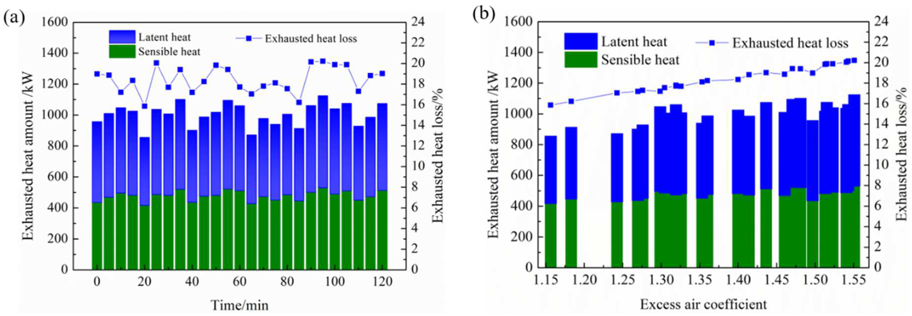
4.3.1. Exhausted Heat Amount and Exhausted Heat Loss of the HPR

Figure 5 shows the exhausted heat amount and exhausted heat loss of the HPR. As shown in Figure 5a, the exhausted heat amount of the flue gas was 855~1125 kW, of which the latent heat was 439~595 kW. The total exhausted heat loss of HPR was 15.8~20.2%, and the latent heat accounted for 50.9~54.5% of total exhausted heat. As the excess air coefficient increased, the flue gas volume flow rate increased, while the reformer’s exhausted gas temperature tended to be stable; thus, the exhausted heat amount and exhausted heat loss increased, as shown in Figure 5b.

4.3.2. Recovery Amount and the Utilization Ratio of Flue Gas Waste Heat of the FGCHE

The recovery amount and utilization ratio of flue gas waste heat and its variation with excess air coefficient and outlet temperature of the flue gas are presented in Figure 6. In Figure 6a, the flue gas waste heat recovery amount was 649~859 kW, of which the latent heat was 271~413.3 kW, accounting for 41.3~48.1% of the flue gas waste heat recovery amount. The utilization ratio of flue gas waste heat was 74~81.9%. As shown in Figure 6b, with the excess air coefficient increasing, the recovery amount of flue gas waste heat increased, and the utilization ratio of flue gas waste heat was relatively stable. Because the amount of flue gas increased with the excess air coefficient, the mass flow rate of flue gas increased, increasing flue gas velocity-enhancing heat transfer, and then the recovery amount of flue gas waste heat increased. Meanwhile, the exhausted heat also increased so that the utilization ratio of flue gas waste heat changes were relatively small. In Figure 6c, the recovery amount and utilization ratio of flue gas waste heat decreased with the flue gas outlet temperature. Because the flue gas inlet temperature was relatively stable, the higher the flue gas outlet temperature, the lower the recovery amount and utilization ratio of flue gas waste heat.

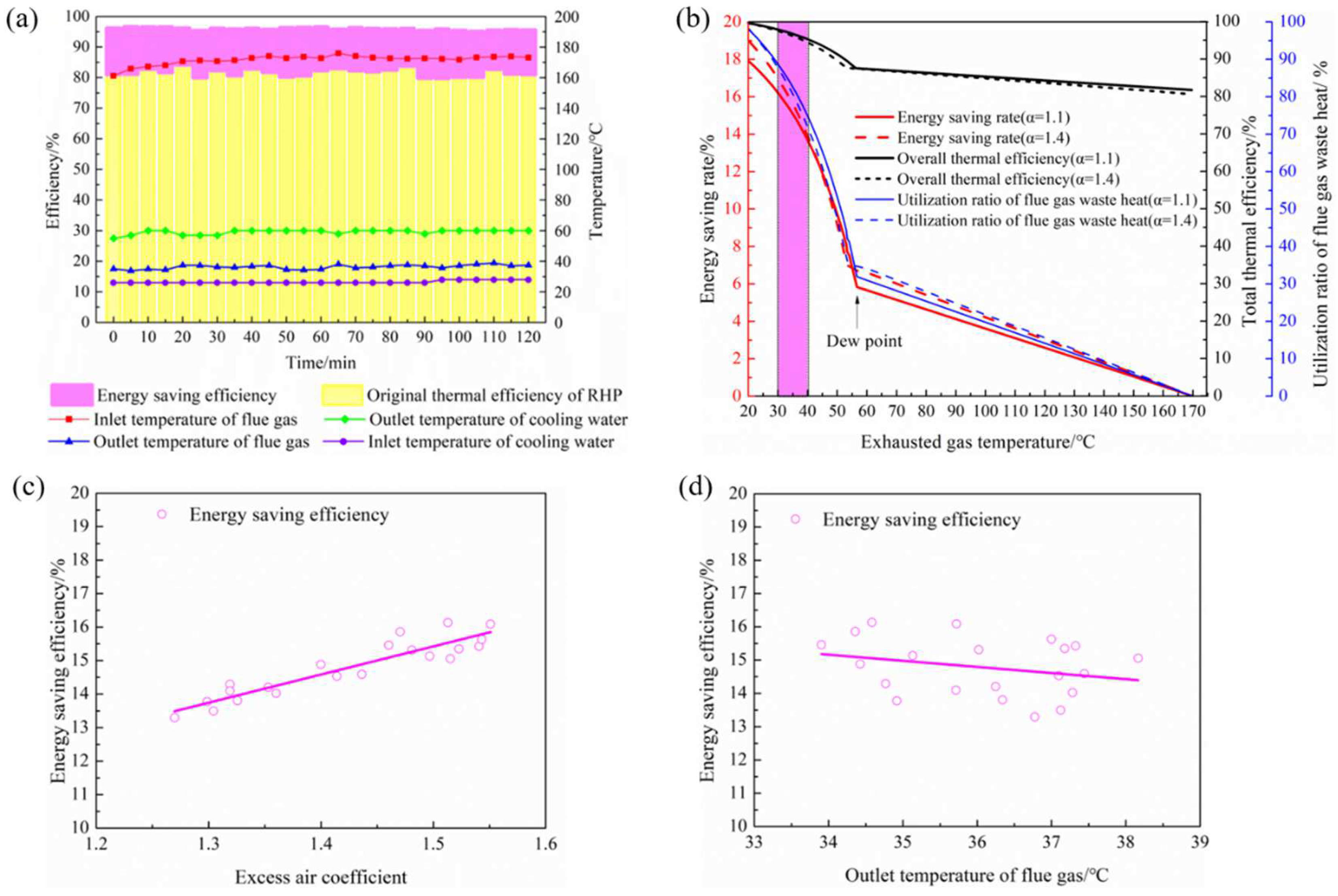
4.4. Energy-Saving Efficiency

The comparisons of the on-site and theoretical energy-saving efficiency and thermal efficiency of the reformer are shown in Figure 7a,b. Figure 7a shows that the on-site original thermal efficiency of the HPR was only 80~84% (HHV). The total thermal efficiency of the reformer system after waste heat recovery reached 95.2~96.6% (HHV), including an energy-saving efficiency of 12~16.1% (average 14.4%) (HHV). Because the flow rate of cooling water was relatively stable, the lower the inlet water temperature, the larger the temperature difference between cooling water and flue gas, which led to the enhancement of convection heat transfer. Thus, both the recovery amount and energy-saving efficiency of flue gas waste heat increased. Figure 7b shows the theoretical energy-saving efficiency and thermal efficiency of the HPR at different exhausted gas temperatures under a state of thermal equilibrium. The results show that when the temperature of flue gas dropped from 170 °C to 30~40 °C under the excess air coefficient 1.1~1.4 (flue gas water dew point 53.3~56.6 °C), the theoretical energy-saving efficiency was 13~17% (HHV), the theoretical total thermal efficiency of the HPR was 94.6~97.9% (HHV), and the theoretical utilization ratio of flue gas waste heat was 72~89%. The on-site measurement result of energy-saving efficiency, the utilization ratio of flue gas waste heat, and thermal efficiency of HPR were consistent with the theoretical calculation values. Figure 7c,d presents the variation in energy-saving efficiency with excess air coefficient and outlet temperature of flue gas. The energy-saving efficiency increases with the excess air coefficient, as shown in Figure 7c. Because the flue gas volume flow rate and flue gas waste heat recovery increased with the excess air coefficient, the energy-saving efficiency correspondingly increased. Figure 7d indicates that the energy-saving efficiency decreased along with the raising flue gas outlet temperature. Because the flue gas inlet temperature was relatively stable, the difference between the flue gas inlet and outlet temperature was reduced, so the recovery amount of flue gas waste heat and energy saving rate decreased.

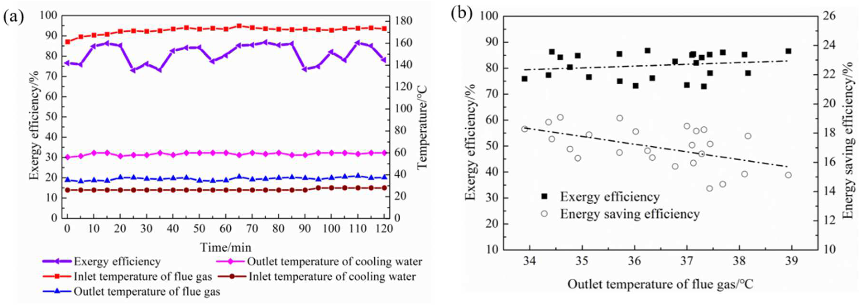
4.5. Exergy Efficiency

Figure 8 presents the exergy efficiency and its variation with the outlet temperature of flue gas. As shown in Figure 8a, the exergy efficiency of the FGCHE reached 73~86.8% under the conditions that the flue gas temperature dropped from 161.3~175.9 °C to 33.9~38.9 °C, and the cooling water temperature rose from 26~28 °C to 55~60 °C. The variations in exergy efficiency and energy-saving efficiency with flue gas outlet temperature are shown in Figure 8b. The exergy efficiency presents an inverse proportional relation to energy-saving efficiency. As flue gas outlet temperature decreased, the energy-saving efficiency increased, while exergy efficiency slightly decreased.

4.6. Analysis of Socio-Economic and Environmental Benefits

An LT-DWHRS was used to heat demineralized cooling water for the captive power plant at a low temperature of 26~28 °C. The exhausted gas temperature was reduced from 161.3~175.9 °C to 33.9~38.9 °C, and the energy-saving efficiency was 12~16.1% (HHV). The results of energy-saving, socio-economic, and environmental benefits of the FGCHE for an HPR system are shown in Figure 9.
From the perspective of energy saving benefits, the average consumption of PSA gas for the reformer combustion of the hydrogen production unit reached 1967.6 Nm3/h, and the energy-saving efficiency was up to 12~16.1% (average 14.4%). The unit price of PSA gas was 1.6 RMB/Nm3. When the annual operation time was up to 8000 h, the annual PSA gas consumption of the HPR was saved by 1.889~2.534 million Nm3/a, equivalent to 643.7~863.6 tce/a. The annual PSA gas saving fee reached 3.022~4.055 million RMB/a. The investment cost of the waste heat recovery system was 1.8 million RMB. The payback period was about 5.3~7.2 months (average 5.9 months). The energy saving and economic benefits are remarkable.
From the perspective of environmental performance, the annual savings for PSA gas reduced carbon dioxide emissions by 2620~3516 t/a. The annual pollutant emissions of NOx and SO2 were reduced by 299.6~401.9 kg/a and 17.9~24.0 kg/a. Thus, the LT-DWHRS can effectively reduce carbon dioxide, pollutant emissions, and improve the air quality of the refinery area.

5. Summary and Conclusions

Considering the contradiction between energy growth and the achievement of carbon peaking and carbon neutrality, the deep waste heat recovery of industrial exhaust gas, with the aim of efficiency improvement and heat loss reduction like that of the LT-DWHRS applied in this study, is a promising and practical exploration for sustainable development. In this regard, a new FGCHE is proposed to deeply recover the low-temperature waste heat of flue gas from the HPR. The on-site test and practical application of FGCHE are investigated to evaluate its waste heat recovery performance. The socio-economic and environmental benefits are also analyzed. The key conclusions are drawn as follows:
(1)
The FGCHE reduced the exhausted gas temperature from 161.3~175.9 °C to 33.9~38.9 °C, and the utilization ratio of flue gas waste heat was 74~81.9%, of which the latent heat accounted for 41.3~48.1%. The energy-saving efficiency was 12~16.1% (HHV), and the total thermal efficiency of the HPR system reached 95.2~96.6% (HHV). The exergy efficiency was 73~86.8%. The flue gas pressure drop of the FGCHE was rarely 20~30 Pa.
(2)
After the exhausted gas temperature drops to the dew point, 11.6~16.3 t/d flue gas condensed water can be recovered. The condensed water can purify NOx and SO2 in the flue gas to a certain extent.
(3)
The annual PSA gas saving was 1.889~2.534 million Nm3/a, which is equivalent to 643.7~863.6 tce/a. Around 3.022~4.055 million RMB/a of the fuel gas cost can be saved after using the FGCHE. The CO2, NOx, and SO2 emissions were reduced by 2620~3516 t/a, 299.6~401.9 kg/a, and 17.9~24.0 kg/a, respectively. The payback period was 5.3~7.2 months. The energy saving, carbon reduction, and economic benefits of the FGCHE for reformers are significant.
China’s crude oil processing volume reached 703.554 million tons in 2021, equivalent to 100.597 million tons of standard coal. If the energy consumption of refining accounts for 8%~10% of total crude oil processing volume, then the refining energy consumption reaches 80.407~100.51 million tons of standard coal. If the flue gas deep waste heat recovery technology is extended to the whole refinery heating furnaces, and the thermal efficiency of the heating furnaces are improved by 12%, then the annual saving amount of standard coal will reach 964.9~12.06 million tons/a, which has huge energy-saving, socio-economic, and environmental benefits.

Author Contributions

All authors contributed to this paper. Research concept, L.M. and S.W.; Figures, L.M. and J.L. (Junhui Lu); Methodology, S.W. and G.L.; Validation, L.M., J.L. (Junhui Lu) and L.Z.; Formal analysis, L.M. and Y.L.; Investigation, L.M. and G.L.; Resources, G.L. and L.Z.; Data curation, S.W. and Y.L.; Writing—original draft preparation, L.M.; Writing—review and editing, S.W., Y.L. and G.L.; Supervision, S.W. and J.L. (Jincheng Liu); Project leader, S.W.; Funding acquisition, L.M., S.W. and J.L. (Junhui Lu). All authors have read and agreed to the published version of the manuscript.

Funding

This research was supported by the BUCEA Doctor Graduate Scientific Research Ability Improvement Project (DG2022015), Beijing Scholars Program (2015No.022), the National Key Research and Development Program of China (2016YFB0601100), and the R&D Program of Beijing Municipal Education Commission (KM202310016006). We also thank the editors and the anonymous reviewers for their valuable comments and suggestions on our manuscript.

Institutional Review Board Statement

Not applicable.

Informed Consent Statement

Not applicable.

Data Availability Statement

Data is contained within the article.

Conflicts of Interest

The authors declare no conflict of interest.

Nomenclature

AiEquivalent area corresponding to the measuring points, m2Sw,outOutlet specific entropy of cooling water, kJ/(kg∙K)
ANCFAnnual net capital flow, RMB/monthtdFlue gas dew point temperature, °C
cp,fSpecific heat capacity of flue gas, kJ/(kg·K)tfAverage temperature of flue gas, °C
cp,wSpecific heat capacity of cooling water, kJ/(kg·K)tf,iMeasuring temperature at different points, °C
df,inFlue gas inlet moisture content, g/kgtf,inFlue gas inlet temperature, °C
df,outFlue gas outlet moisture content, g/kgtf,outFlue gas outlet temperature, °C
ΔEfExergy difference of flue gas, kJtw,inCooling water inlet temperature, °C
ΔEwExergy difference of cooling water, kJtw,outCooling water outlet temperature, °C
ECO2Total CO2 emissions per year depending on variant, kg/aTarAnnual running time, h
ENOxTotal NOx emissions per year depending on variant, kg/aT0Ambient temperature, K
ESO2Total SO2 emissions per year depending on variant, kg/aVfFlue gas volume per unit of fuel gas, m3/Nm3
GavAverage fuel gas volume flow rate, Nm3/hGreek symbols
GgFuel gas volume flow rate, Nm3/sαExcess air coefficient
GsgAnnual saving amount of PSA gas, Nm3/aηEnergy-saving efficiency, %
hamFlue gas enthalpy value at standard ambient temperature, kJ/kgη1Thermal efficiency of the reformer, %
hcwFlue gas condensed water enthalpy, kJ/kgηtTotal thermal efficiency of the reformer, %
hf,inFlue gas inlet enthalpy, kJ/kgηhUtilization ratio of flue gas waste heat, %
hf,outFlue gas outlet enthalpy, kJ/kgηexExergy efficiency, %
hw,inInlet enthalpy of cooling water, kJ/kgρFlue gas density under standard condition, kg/m3
hw,outOutlet enthalpy of cooling water, kJ/kgψDehumidification rate of flue gas, %
HHigher heating value of fuel gas, kJ/Nm3 χ Heat balance deviation, %
ICInvestment cost, RMBεPSA gas factor for CO2, NOx, and SO2 emissions, kg/Nm3
mcwFlue gas condensed water flow rate, kg/sSubscripts
mfDry flue gas mass flow rate, kg/samAmbient
mwMass flow rate of cooling water, kg/scwCondensed water
NMeasuring numberdDew point
PH2OPartial pressure of water vapor in flue gas, barehExhausted heat
PBPPayback period, monthexExergy
q2Heat loss of exhausted gas, %fFlue gas
q3Heat loss of unburned fuel gas, %gFuel gas
q4Heat loss of unburned solid, %hHeat recovery
q5Heat loss of furnace body, %lLatent
q6Heat loss of ash, %inInlet
QgFuel gas calorific capacity, kWoutOut
QehExhausted heat amount, kWsSensible
QfReleasing heat amount of flue gas, kWsgSaving gas
Qf,sSensible heat amount of flue gas, kWtTotal
Qf,lLatent heat amount of flue gas, kWT0Standard ambient temperature
QhFlue gas waste heat recovery amount, kWwWater
QwHeat absorption amount of cooling water, kWCO2Carbon dioxide
Sf,inInlet-specific entropy of flue gas, kJ/(kg∙K)H2OWater vapor
Sf,outOutlet-specific entropy of flue gas, kJ/(kg∙K)NOxNitrogen oxides
Sw,inInlet-specific entropy of cooling water, kJ/(kg∙K)SO2Sulfur dioxide

References

  1. National Bureau of Statistics. Statistical Communiqué of the People’s Republic of China on the 2022 National Economic and Social Development. Available online: http://www.stats.gov.cn/xxgk/sjfb/zxfb2020/202302/t20230228_1919001.html (accessed on 10 May 2023). (In Chinese)
  2. Lin, Y.C.; Chong, C.H.; Ma, L.W.; Li, Z.; Ni, W.D. Quantification of waste heat potential in China: A top-down Societal Waste Heat Accounting Model. Energy 2022, 261, 125194. [Google Scholar] [CrossRef]
  3. Sgarbossa, F.; Arena, S.; Tang, O.; Peron, M. Renewable hydrogen supply chains: A planning matrix and an agenda for future research. Int. J. Prod. Econ. 2023, 255, 108674. [Google Scholar] [CrossRef]
  4. Zare, A.A.D.; Yari, M.; Nami, H.; Mohammadkhani, F. Low-carbon hydrogen, power and heat production based on steam methane reforming and chemical looping combustion. Energy Convers. Manag. 2023, 279, 116752. [Google Scholar] [CrossRef]
  5. Young, B.; Hawkins, T.R.; Chiquelin, C.; Sun, P.P.; Gracida-Alvarez, U.R.; Elgowainy, A. Environmental life cycle assessment of olefins and by-product hydrogen from steam cracking of natural gas liquids, naphtha, and gas oil. J. Clean. Prod. 2022, 359, 131884. [Google Scholar] [CrossRef]
  6. Lei, X.J.; Wang, Y.H.; Zhang, Y.; Li, Y.; Xu, H. Simulation and analysis of reactor for methane steam reforming. Nat. Gas Chem. Ind. 2017, 42, 67–76. (In Chinese) [Google Scholar]
  7. Larrinaga, P.; Campos-Celador, Á.; Legarreta, J.; Diarce, G. Evaluation of the theoretical, technical and economic potential of industrial waste heat recovery in the Basque Country. J. Clean. Prod. 2021, 312, 127494. [Google Scholar] [CrossRef]
  8. Yang, Z.; Korobko, V.; Radchenko, M.; Radchenko, R. Improving Thermoacoustic Low-Temperature Heat Recovery Systems. Sustainability 2022, 14, 12306. [Google Scholar] [CrossRef]
  9. Zhao, J.; Ma, L.; Zayed, M.E.; Elsheikh, A.H.; Li, W.J.; Yan, Q.; Wang, J.C. Industrial reheating furnaces: A review of energy efficiency assessments, waste heat recovery potentials, heating process characteristics and perspectives for steel industry. Process Saf. Environ. Prot. 2021, 147, 1209–1228. [Google Scholar] [CrossRef]
  10. Nami, H.; Anvari-Moghaddam, A.; Arabkoohsar, A.; Razmi, A.R. 4E Analyses of a Hybrid Waste-Driven CHP–ORC Plant with Flue Gas Condensation. Sustainability 2020, 12, 9449. [Google Scholar] [CrossRef]
  11. Xiao, L.H.; Yang, M.L.; Yang, Y.; Huang, S.M.; Han, Z.H.; Wu, D. Performance study of transport membrane condenser using condensate water to recover water and heat from flue gas. J. Clean. Prod. 2022, 371, 133573. [Google Scholar] [CrossRef]
  12. Lu, J.H.; Tang, J.J.; Li, J.M.; Wang, S.L. The comparison of adsorption characteristics of CO2/H2O and N2/H2O on activated carbon, activated alumina, zeolite 3A and 13X. Appl. Therm. Eng. 2022, 213, 118746. [Google Scholar] [CrossRef]
  13. Shamsi, S.S.M.; Negash, A.A.; Cho, G.B.; Kim, Y.M. Waste Heat and Water Recovery System Optimization for Flue Gas in Thermal Power Plants. Sustainability 2019, 11, 1881. [Google Scholar] [CrossRef] [Green Version]
  14. Lan, Y.C.; Wang, S.L.; Lu, J.H.; Zhai, H.X.; Mu, L.B. Comparative analysis of organic rankine cycle, Kalina cycle and thermoelectric generator to recover waste heat based on energy, exergy, economic and environmental analysis method. Energy Convers. Manag. 2022, 273, 116401. [Google Scholar] [CrossRef]
  15. Ghorbani, B. Development of an Integrated Structure for the Tri-Generation of Power, Liquid Carbon Dioxide, and Medium Pressure Steam Using a Molten Carbonate Fuel Cell, a Dual Pressure Linde-Hampson Liquefaction Plant, and a Heat Recovery Steam Generator. Sustainability 2021, 13, 8347. [Google Scholar] [CrossRef]
  16. Wang, Y.J.; Chen, Y.; Wang, K.; Li, X.F. Performance evaluation and thermal analysis of heat pipe flue gas waste heat utilization system. Energy Rep. 2022, 8, 210–217. [Google Scholar] [CrossRef]
  17. Szulc, P.; Tietze, T.; W’ojs, K. Studies on the process of recovering low-temperature waste heat from a flue gas in a pilot-scale plant. Chem. Process Eng. 2016, 37, 529–543. [Google Scholar] [CrossRef] [Green Version]
  18. Wang, P.; Xie, C.F.; Xu, S.M.; Ge, Y.L. Application of Energy-saving Technology on Furnaces of Oil Refining Units. Procedia Environ. Sci. 2012, 12, 387–393. [Google Scholar]
  19. Karimi, M.; Kargari, A.; Behbahani-nia, S.A.; Sanaeepur, H. Heat recovery and optimizing design of furnaces in the gasoline-kerosene units of Tabriz Oil Refining Company. Appl. Therm. Eng. 2019, 161, 114136. [Google Scholar] [CrossRef]
  20. Mihelić-Bogdanić, A.; Špelić, I. Energy Efficiency Optimization in Polyisoprene Footwear Production. Sustainability 2022, 14, 10799. [Google Scholar] [CrossRef]
  21. Madzivhandila, V.A.; Majozi, T.; Zhelev, T.K. Recovery of Flue Gas Energy in Heat-Integrated Gasification Combined Cycle (IGCC) Power Plants Using the Contact Economizer System. Energy Fuel 2011, 25, 1529–1536. [Google Scholar] [CrossRef]
  22. Alviz-Meza, A.; Shah, S.I.; Kafarov, V.; Peña-Ballesteros, D.Y. Fireside corrosion of 9Cr-1Mo steel at high temperatures, in the acid flue gas from an oil refinery. Corros. Sci. 2021, 193, 109878. [Google Scholar] [CrossRef]
  23. Zuo, W.J.; Zhang, X.Y.; Li, Y.Z. Review of flue gas acid dew-point and related low temperature corrosion. J. Energy Inst. 2020, 93, 1666–1677. [Google Scholar] [CrossRef]
  24. Wang, Z.Y.; Zhang, X.Y.; Li, Z. Evaluation of a flue gas driven open absorption system for heat and water recovery from fossil fuel boilers. Energy Convers. Manag. 2017, 128, 57–65. [Google Scholar] [CrossRef]
  25. Shang, S.; Li, X.T.; Chen, W.; Wang, B.L.; Shi, W.X. A total heat recovery system between the flue gas and oxidizing air of a gas-fired boiler using a non-contact total heat exchanger. Appl. Energy 2017, 207, 613–623. [Google Scholar] [CrossRef]
  26. Hong, S.K.; Park, S.; Jeon, S.; Lee, K. Experimental study on heat transfer characteristics of water-spray-bed heat exchanger. J. Mech. Sci. Technol. 2015, 29, 2243–2247. [Google Scholar] [CrossRef]
  27. Zhang, Q.L.; Niu, Y.; Yang, X.H.; Sun, D.H.; Xiao, X.; Shen, Q.; Wang, G. Experimental study of flue gas condensing heat recovery synergized with low NOx emission system. Appl. Energy 2020, 269, 115091. [Google Scholar] [CrossRef]
  28. Bao, A.N.; Wang, D.X.; Lin, C.X. Nanoporous membrane tube condensing heat transfer enhancement study. Int. J. Heat Mass Tran. 2015, 84, 456–462. [Google Scholar] [CrossRef]
  29. Zhang, W.; Wang, S.L.; Mu, L.B. Condensation heat transfer characteristics of flue gas on anti-corrosive coated finned tubes. Appl. Therm. Eng. 2021, 189, 116672. [Google Scholar] [CrossRef]
  30. Gao, D.; Li, Z.H.; Zhang, H.; Chen, H.P.; Cheng, C.; Liang, K. Moisture and latent heat recovery from flue gas by nonporous organic membranes. J. Clean. Prod. 2019, 225, 1065–1078. [Google Scholar] [CrossRef]
  31. Wang, X.; Zhuo, J.K.; Liu, J.M.; Li, S.Q. Synergetic process of condensing heat exchanger and absorption heat pump for waste heat and water recovery from flue gas. Appl. Energy 2020, 261, 114401. [Google Scholar] [CrossRef]
  32. Liu, G.C.; Yang, L.J.; Wang, L.D.; Wang, S.L.; Liu, C.Y.; Wang, J. Corrosion behavior of electroless deposited Ni-Cu-P coating in flue gas condensate. Surf. Coat. Tech. 2010, 204, 3382–3386. [Google Scholar] [CrossRef]
  33. Yang, B.; Yuan, W.X. Performance analysis of a novel two-stage membrane waste heat recovery system. Appl. Therm. Eng. 2022, 215, 118952. [Google Scholar] [CrossRef]
  34. Mehdizadeh-Fard, M.; Pourfayaz, F.; Maleki, A. Exergy analysis of multiple heat exchanger networks: An approach based on the irreversibility distribution ratio. Energy Rep. 2021, 7, 174–193. [Google Scholar] [CrossRef]
  35. Li, Y.; An, H.L.; Li, W.T.; Zhang, S.Y.; Jia, X.Q.; Fu, L. Thermodynamic, energy consumption and economic analyses of the novel cogeneration heating system based on condensed waste heat recovery. Energy Convers. Manag. 2018, 177, 671–681. [Google Scholar] [CrossRef]
  36. Hernandez, A.G.; Cullen, J.M. Exergy: A universal metric for measuring resource efficiency to address industrial decarbonisation. Sustain. Prod. Consump. 2019, 20, 151–164. [Google Scholar] [CrossRef]
  37. Hamedi, M.; Omidkhah, M.; Sadrameli, S.M.; Manesh, M.H.K. Exergetic, exergoeconomic, and exergoenvironmental analyses of an existing industrial olefin plant. Sustain. Energy Techn. 2022, 52, 102175. [Google Scholar] [CrossRef]
  38. Utlu, Z.; Hepbasli, A. A review and assessment of the energy utilization efficiency in the Turkish industrial sector using energy and exergy analysis method. Renew. Sust. Energy Rev. 2007, 11, 1438–1459. [Google Scholar] [CrossRef]
  39. Shariati, M.H.; Farhadi, F. Exergy Analysis of Waste Heat Recovery Section in Steam-Natural Gas Reforming Process. Energy Fuel 2015, 29, 3322–3327. [Google Scholar] [CrossRef]
  40. Zhang, Y.X.; Wang, S.L.; Zhang, W.; Ding, Y.D.; Cheng, M.; Mu, L.B.; Zhao, X.D. Investigation of the condensation heat-transfer between the wet air and 3-D finned-tube heat exchanger surface with different anti-corrosion coatings. Exp. Heat Transf. 2022, 35, 399–418. [Google Scholar] [CrossRef]
  41. Che, D.F. Boilers-Theory, Design and Operation; Xi’an Jiaotong University Press: Xi’an, China, 2008; ISBN 9787560525310. [Google Scholar]
  42. Mu, L.B.; Wang, S.L.; Zhu, F.; Sun, H.J.; Tian, C.R.; Zhang, L.S. Application and energy saving analysis of the condensing heat depth recovery system for boilers flue gas. Heat. Vent. Air Cond. 2020, 50, 65–69. (In Chinese) [Google Scholar]
  43. Cheng, M.; Chen, Z.Y.; Liao, Q.; Gu, Y.H.; Ding, Y.D. Heat transfer and pressure drop characteristics of 3-D finned tube heat exchanger in ash-laden flue gas. Int. J. Heat Mass Tran. 2021, 170, 120982. [Google Scholar] [CrossRef]
  44. Ministry of Housing and Urban-Rural Development of the People’s Republic of China. Flue Gas Condensing Type Heat Exchanger Units for Gas-Fired Boilers (CJ/T 515-2018); Standards Press of China: Beijing, China, 2018. (In Chinese) [Google Scholar]
  45. Ma, H.Q.; Liang, N.; Liu, Y.M.; Luo, X.M.; Hou, C.Q.; Wang, G. Experimental study on novel waste heat recovery system for sulfide-containing flue gas. Energy 2021, 227, 120479. [Google Scholar] [CrossRef]
  46. Chinese Academy of Science. Scientific Databases-Engineering Chemistry Database. Available online: https://www.cas.cn/ky/kycc/kxsjk/ (accessed on 6 March 2023). (In Chinese).
  47. Zhang, W.; Wang, S.L.; Mu, L.B.; Jamshidnia, H.; Zhao, X.D. Investigation of the forced-convection heat-transfer in the boiler flue-gas heat recovery units employing the real-time measured database. Energy 2022, 238, 121715. [Google Scholar] [CrossRef]
  48. Fei, Y.T. Error Theory and Data Processing, 7th ed.; China Machine Press: Beijing, China, 2019; ISBN 9787111495246. (In Chinese) [Google Scholar]
Figure 1. Process flow chart of the HPR.
Sustainability 15 09495 g001
Figure 2. The LT-DWHRS for exhausted gas of the HPR.
Sustainability 15 09495 g002
Figure 3. Operating parameters of the LT-DWHRS. (a) The PSA gas flow rate, load rate of the HPR, and excess air coefficient. (b) Flue gas temperature and flow pressure drop. (c) Temperature and flow rate of cooling water. (d) Flue gas condensed water flow rate.
Sustainability 15 09495 g003
Figure 4. Dew point temperature and dehumidification rate. (a) Variation in dew point, moisture content, and excess air coefficient. (b) Variation in dehumidification rate. (c) Variation in dew point, dehumidification rate, and moisture content of flue gas with excess air coefficient.
Sustainability 15 09495 g004
Figure 5. Exhausted heat amount and exhausted heat loss of the HPR. (a) Exhausted heat amount and exhausted heat loss with time. (b) Variation in exhausted heat amount and exhausted heat loss with excess air coefficient.
Sustainability 15 09495 g005
Figure 6. Recovery amount and the utilization ratio of flue gas waste heat and its variation: (a) Recovery amount and the utilization ratio of flue gas waste heat. (b) Variation in recovery amount and the utilization ratio of flue gas waste heat with excess air coefficient. (c) Variation in recovery amount and the utilization ratio of flue gas waste heat with flue gas outlet temperature.
Sustainability 15 09495 g006
Figure 7. Energy-saving efficiency and its variation: (a) On-site energy-saving efficiency and thermal efficiency. (b) Theoretical energy-saving efficiency and thermal efficiency. (c) Variation in energy-saving efficiency with excess air coefficient. (d) Variation in energy-saving efficiency with the outlet temperature of flue gas.
Sustainability 15 09495 g007
Figure 8. Exergy efficiency and its variation: (a) Exergy efficiency of the FGCHE. (b) Variation in exergy efficiency and energy-saving efficiency with the outlet temperature of flue gas.
Sustainability 15 09495 g008
Figure 9. Energy saving, emission reduction, and economic benefits.
Sustainability 15 09495 g009
Table 1. Application of different heat exchangers for waste heat recovery of flue gas.
AuthorsFuelsEnergy-Saving EquipmentFlue Gas Inlet Temperature (°C)Flue Gas Outlet Temperature (°C)Inlet Temperature of the Heated Medium (°C)Outlet Temperature of the Heated Medium (°C)Waste Heat Recovery Type
Wang et al. [16]Bituminous coalHeat pipe heat exchanger156.8~158.5129.8~131.240.9~42.288.5~89.3Sensible heat recovery
Szulc et al. [17]Lignite coalHeat exchanger15560-90
Wang et al. [18]Fuel oilAir preheater 285~347160~16580155~225
Karimi et al. [19]Natural gasEconomizer306203118254
Miheli-Bogdani et al. [20]Natural gasAir preheater 20466.9324186
Madzivhandila et al. [21]SyngasContact economizer 90>60--
Shang et al. [25]Natural gasNon-contact total heat exchanger53.525.7044.6Sensible and latent heat recovery
Hong et al. [26] Natural gasTube-type heat exchanger38~5528~3211~1316~18
Zhang et al. [27]Natural gas Direct contact heat exchange 203.5~209.845~5543.750.8
Bao et al. [28]Natural gasTransport membrane condenser64.7~93.545.2~57.319.1–44.633.5–56.1
Table 2. PSA gas components and calorific value.
PSA Gas ComponentsH2CH4COCO2H2S
Volume fraction29.6%13.4%3.4%53.6%≤5 mg/m3
Higher heating value (HHV)9970 kJ/Nm3
Lower heating value (LHV)8433 kJ/Nm3
Table 3. PSA gas consumption, temperature, and components of flue gas from the HPR.
PSA Gas Volume Flow RateTemperature Components
N2CO2H2OO2SO2NOx
Nm3/h°C%%%%mg/Nm3mg/Nm3
1580~2354161~191.658~62.29~9.814.5~18.13.42~6.231.5~2.623~38.6
Table 4. Energy-saving and carbon-reducing potential analysis of the FGCHE under design conditions.
ContentsUnitsParameters
PSA gas volume flow rateNm3/h2354
Excess air coefficient/1.3
Flue gas volume flow rateNm3/h8330
Inlet temperature of flue gas°C170
Outlet temperature of flue gas°C40
Inlet moisture content of flue gas g/kg111.926
Outlet moisture content of flue gasg/kg49.532
Cooling water flow ratem3/h25
Inlet temperature of cooling water°C25
Outlet temperature of cooling water°C56
Exhausted heat amount kW1203
Latent heat ratio in exhausted heat %54.3
Exhausted heat loss (HHV)%18.9
Flue gas waste heat recovery amountkW902
Utilization ratio of flue gas waste heat%64.6
Energy-saving efficiency (HHV)% 13.8
Dehumidification rate%55.7
Flue gas condensed water flow ratet/d14.9
Annual operation timeh8000
Annual saving amount of PSA gas104 Nm3/a308.3
Annual reduction in CO2 emissionst/a4278
Table 5. Instruments and their accuracy.
NO.InstrumentsCompaniesTypeAccuracyParameters
1Gas flowmeterTancy Instrument Group Co., Ltd. (Wenzhou, China)FCM-II ±1.5%PSA gas volume flow rate
2Ultrasonic flowmeterMicronics Ltd. (Loudwater, UK)PF300±1%Cooling water volume flow rate
3Platinum resistance thermometerSiemens AG (Munich, Germany)Siemens-Pt100±0.01 °CCooling water temperature
4Armored thermocoupleSpectris Instrumentation and Systems Shanghai Ltd. (Shanghai, China)T-type±0.1 °CFlue gas temperature
5Flue gas analyzerEcom GmbH (Assamstadt, Germany)Ecom-J2KNO2: ±0.2%
CO2: ±0.3%
NOx: ±2 ppm
SO2: ±5 ppm
Flue gas components
6Digital micromanometerEcom GmbH (Assamstadt, Germany)Ecom-DPH±3%Flue gas flow pressure drop
7Agilent Agilent Technology Co., Ltd. (Santa Clara, CA, USA)HP34970A±0.004%Data collection
8Temperature and humidity recorderEcom GmbH (Assamstadt, Germany)Ecom-TFS±0.1 °C, ±0.1%Air temperature and humidity
9Electronic scaleTianfu Co., Ltd. (Zhengzhou, China)DT-30K±1 gFlue gas condensate flow
10StopwatchShenzhen Huibo Industry and Trade Co., Ltd. (Shenzhen, China)PC396±0.01 sTime
11Portable pH TesterMettler Toledo (Greifensee, Switzerland)SevenGo-SG2±0.01 pHpH of the condensed water
Table 6. Test results of flue gas condensed water.
pHIron ConcentrationSulfide ConcentrationSulfate ConcentrationChloride ConcentrationNitrate Nitrogen ConcentrationNitrite Nitrogen Concentration
μg/Lmg/Lmg/Lmg/Lmg/Lmg/L
4.6039.70.005 4.61 1.12 0.35 0.94
Disclaimer/Publisher’s Note: The statements, opinions and data contained in all publications are solely those of the individual author(s) and contributor(s) and not of MDPI and/or the editor(s). MDPI and/or the editor(s) disclaim responsibility for any injury to people or property resulting from any ideas, methods, instructions or products referred to in the content.

