Article

Study on the Fracture Evolution Characteristics of Existing Defect Lining under Unsymmetrical Load

1
School of Civil Engineering, Shijiazhuang Tiedao University, Shijiazhuang 050043, China
2
Key Laboratory of Large Structure Health Monitoring and Control, Shijiazhuang Tiedao University, Shijiazhuang 050043, China
3
School of Safety Engineering and Emergency Management, Shijiazhuang Tiedao University, Shijiazhuang 050043, China
4
Geotechnical and Structural Engineering Research Center, Shandong University, Jinan 250061, China
5
School of Civil Engineering, Beijing Jiaotong University, Beijing 100044, China
*
Author to whom correspondence should be addressed.
Sustainability 2023, 15(12), 9531; https://doi.org/10.3390/su15129531
Submission received: 17 March 2023 / Revised: 4 June 2023 / Accepted: 12 June 2023 / Published: 14 June 2023

Abstract

:
In order to explore the fracture evolution characteristics of existing defect lining structures under unsymmetrical loads, unsymmetrical failure model tests of three working conditions, namely, intact lining, vault defect, and arch waist defect, were carried out. Acoustic emission (AE) technology was used to detect the lining cracks from microscopic to macroscopic. The relationship between the accumulated energy of AE and the relative load was established, and a fracture evolution model of lining based on the cumulative energy of AE was proposed. The results show that the failure process of the intact lining under unsymmetrical load has three stages: “initial crack cracking at the unsymmetrical position → development and formation of main crack → specimen cracking failure”. The load ratio of initial crack cracking is 16.5%, and the load ratio of main crack development and formation is 52.2%. The initial cracking position of the lining under unsymmetrical loads has nothing to do with the existing defect position, with defects occurring at the unsymmetrical position, and the remaining cracks are mainly distributed in the vault, inverted arch and arch foot position. Compared with the intact lining, the ultimate bearing capacity of the vault defect and arch waist defect decreased by 14.2% and 21.3%, and the maximum deformation decreased by 44.6% and 50.6%, respectively. The radial deformation degree in the unsymmetrical position at each stage is basically the same under unsymmetrical load conditions, and it is not affected by the position of the existing defects. The deformation proportion of each stage is concentrated in 5%, 40%, 53%, respectively. We derived the facture evolution of lining based on the accumulated energy of AE, and the quantitative relationship between the damage variable and deformation of the lining under unsymmetrical load was established. When the fracture degree reaches 0.04 and 0.35, the deformation of vault defect lining and the arch waist defect lining is 58.3%, 75.0%, 40.2% and 50.6% earlier than those of the complete lining, respectively. When the fracture degree exceeds 0.6, the growth rate of damage degree is no longer affected by the location of the existing defect.

1. Introduction

Due to the limitations of geological topography and line direction, unsymmetrical tunnels often appear at tunnel entrances and river valleys. This results in the cracking of tunnel linings, the formation of crack diseases, and even in damage to tunnel structures, endangering driving safety [1]. Meanwhile, as the main material of tunnel lining, concrete has heterogeneous and irregular characteristics [2]. As a result, the damage evolution of the lining is a complex and changeable process, while the force of the unsymmetrical tunnels structure is more complex [3]. As a result, traditional detection methods and damage analysis methods struggle to accurately determine the damage degree and evolution characteristics of unsymmetrical tunnels. Therefore, it is necessary to carry out studies of the evolution characteristics of lining fractures under unsymmetrical load conditions.
At present, some research results have been obtained on the force characteristics and the fracture evolution characteristics of tunnel lining under unsymmetrical loads. Zhao Lianheng et al. [4,5,6] introduced the horizontal unsymmetrical load coefficient to optimize the calculation method of surrounding rock pressure distribution in shallowly buried unsymmetrical tunnels. The authors proved that the optimized calculation method has significant asymmetric failures and that the overall deflection of the failure range to the side with a larger buried depth is more in line with the actual engineering situation. She Jian, He Chuan et al. [7,8] studied the deformation, disease and bearing capacity characteristics of structures under conditions of vertical ground pressure caused by unsymmetrical and surrounding rock relaxation. Liu Xuecheng et al. [9,10] analyzed the stiffness attenuation law of the lining structure with numerical calculation inversion based on the model test results, explored the force deformation characteristics, failure forms and damage processes of the tunnel structure under unsymmetrical load, and proposed a mechanical evaluation model for tunnel lining diseases. Lei Mingfeng et al. [11,12] systematically studied the influence law of unsymmetrical surface angle on the surrounding rock pressure of shallow-buried unsymmetrical tunnels by using indoor similar physical model tests. Zhang Zhiguo et al. [13] modified the cohesion of rock and soil mass based via the comprehensive action of horizontal and vertical seismic forces, and then obtained the analytical solution of surrounding rock pressure in shallow-buried unsymmetrical tunnels. However, the research on the evolution characteristics of lining cracks is more discussed through visual detection results such as force, deformation, and stiffness change. While scholars have ignored the detection and analysis of the whole process from initial microscopic damage to macroscopic damage of the lining.
As a typical nondestructive testing technique, acoustic emission (AE) technology is often applied to the damage detection of tunnel lining because it can describe the whole process from microscopic damage to macroscopic damage. Li Junwei et al. [14] derived a mathematical model of the evolution of lining cracking damage based on the relationship between cumulative energy of AE and the relative load of lining, and the damage degree of lining cracking can be inferred preliminarily by CMOD. Amedeo Manuello et al. [15], by collecting acoustic emission signals during the damage evolution of a highway tunnel, proved that the acoustic emission 3D positioning technique can effectively describe the characteristics of crack growth. In the work of Triantis Dimos et al. [16], the dead load stage of the three-point bending test was detected by acoustic emission technology. It has been proved that the F function and p function can effectively describe the attenuation phenomenon at the early stage of the dead load. At the same time, the attenuation phenomenon is more obvious when the load exceeds 80% of the breaking load. In the work of Efe Selman et al. [17], mechanical and acoustic information of reinforced concrete members reinforced by carbon fiber-reinforced polymer (CFRP) was collected. A unitless function “sentry” was proposed based on a logarithmic ratio of variable energy (ES) to acoustic energy (EAC). It has been proved that the “sentry” function can effectively reflect the failure mechanism and failure degree of reinforced concrete members reinforced by carbon fiber-reinforced polymer (CFRP).
In view of this, this paper carries out a model test of existing defect tunnel lining for unsymmetrical loads. The AE signals of the whole process of fracture evolution is analyzed from the microscopic to the macroscopic, and the fracture evolution law of tunnel lining under unsymmetrical load conditions is studied to provide some reference for lining crack performance evaluation and lining maintenance.

2. Model Test Design and Device

2.1. Model Test Device

The self-developed lining horizontal loading model test device was used in the test, as shown in Figure 1. In this test, the influence of self-weight was ignored. The lining was placed horizontally and the pulley plate was set at the bottom to reduce the friction caused by the displacement of the lining in the loading process. The loading system was composed of a ground stress spring, jack and oil pressure control system. A total of 10 independently controlled jacks were provided. By controlling the loading of each jack, various load conditions of tunnel lining can be simulated.
A self-developed lining horizontal loading model test device was used in the test, as shown in Figure 1. In this test, the influence of self-weight was ignored. The lining was placed horizontally, and the pulley plate was set at the bottom to reduce the friction caused by the displacement of the lining in the loading process. The loading system was composed of a ground stress spring, jack, and oil pressure control system. A total of 10 independently controlled jacks were provided. Various load conditions of tunnel lining can be simulated by controlling the loading of each jack.

2.2. Lining Model Preparation and Working Condition Design

In this paper, the Xiangsi Mountain unsymmetrical tunnel of the Guangzhou–Zhanjiang railway was taken as the engineering prototype in the model test. The transverse span of the prototype tunnel was 14.7 m, the height was 11.5 m and the thickness of the lining was 0.5 m. According to the content and purpose of the test, as well as the geometric size of the existing test bench, the similarity ratio of 1:10 was adopted for the test design according to the law of similarity. The transverse span of the model specimen was 1.47 m, the height was 1.15 m, and the thickness of the lining was 0.05 m. Other parameters of the specimen are similar, as shown in Table 1.
In this test, similar materials of C35 concrete were used to cast lining specimens, and the matching materials were ordinary Portland cement comprising PO32.5, fine river sand, stone plaster and water. The specific matching of similar materials is shown in Table 2.
According to existing research [18,19], the key failure locations of the lining structure were vault and arch waist. The cracks occurred in the vault accounted for 79.31% of the total number of cracks, the number of cracks in the arch waist accounted for 43.10% of the total number of cracks, and the cracks in the side wall accounted for 21% of the total number of cracks. It can be seen that the cracking probability of the vault was the largest, followed by that of the arch waist.
Based on this, three kinds of test pieces were designed in this test. Among them, the inner arch and arch waist of the lining were prefabricated. The depth is 1/3 of the lining thickness, and the width is 5 mm. Details are shown in Table 3.

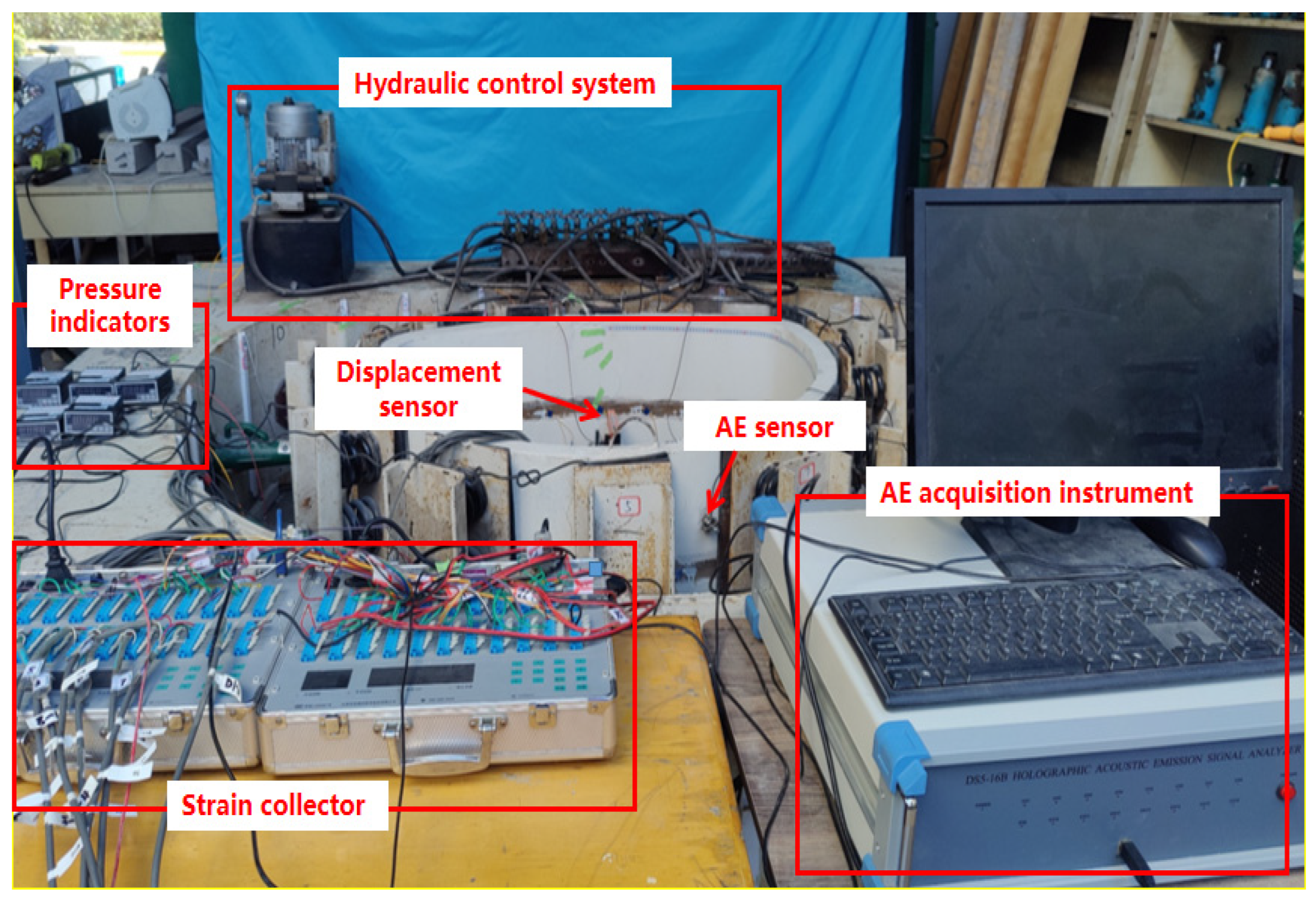
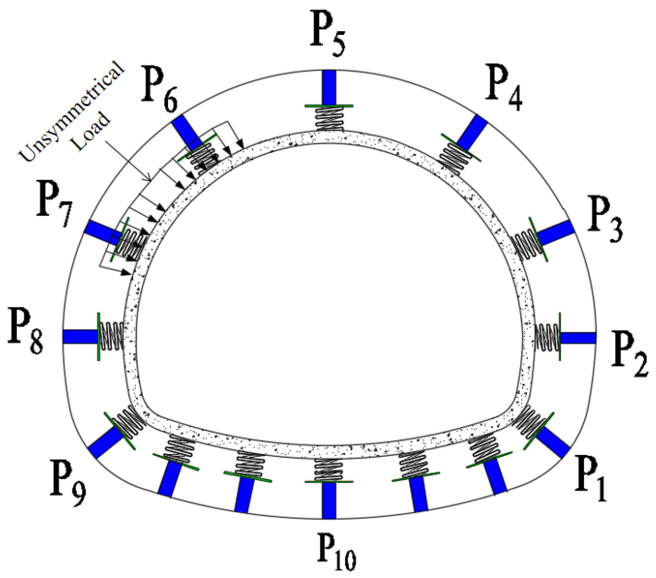
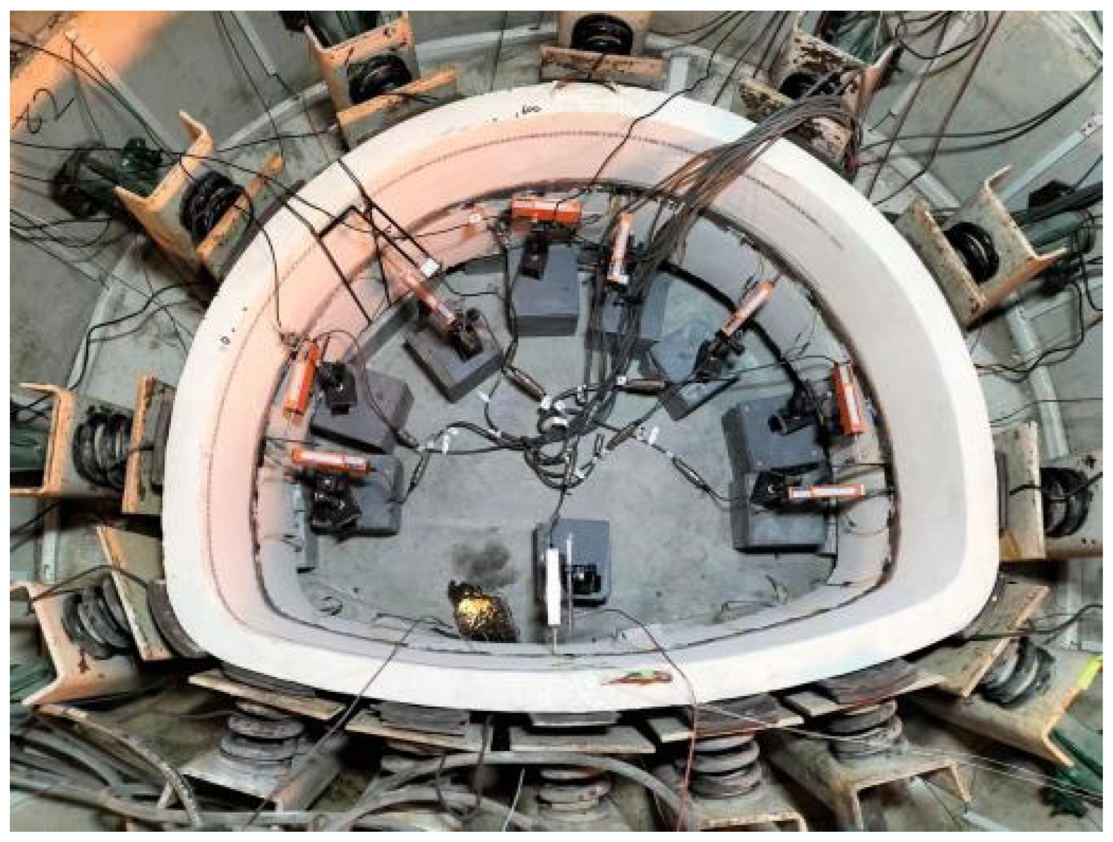
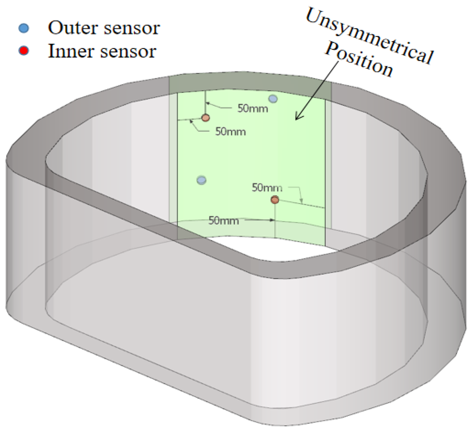
2.3. Test Loading and Sensor Arrangement

In order to meet the requirements of unsymmetrical load in this test, the joint operation mode of P6 and P7 jacks is shown in Figure 2, and the other jacks bear the elastic resistance caused by lining deformation. The test was performed by displacement-controlled loading, with 0.5 mm loading at each level until the component was destroyed.
In this test, displacement meters were used to detect the deformation of lining, and 9 displacement meters were arranged on the inner surface of corresponding lining. The specific positions of displacement meters are shown in Figure 3. The AE was used to detect lining damage. In order to accurately identify the fracture evolution of lining, AE time parameters, sound velocity calibration and other detection parameters were set according to existing research results [20]. Considering the principle of the AE sensor wrapping test specimen, the AE sensors were arranged in a formation of dislocation and cross in a position that was the same distance from the unsymmetrical position and the outer surface boundary. The specific arrangement is shown in Figure 4.

3. Analysis of Lining Cracking Characteristics under Unsymmetrical Load

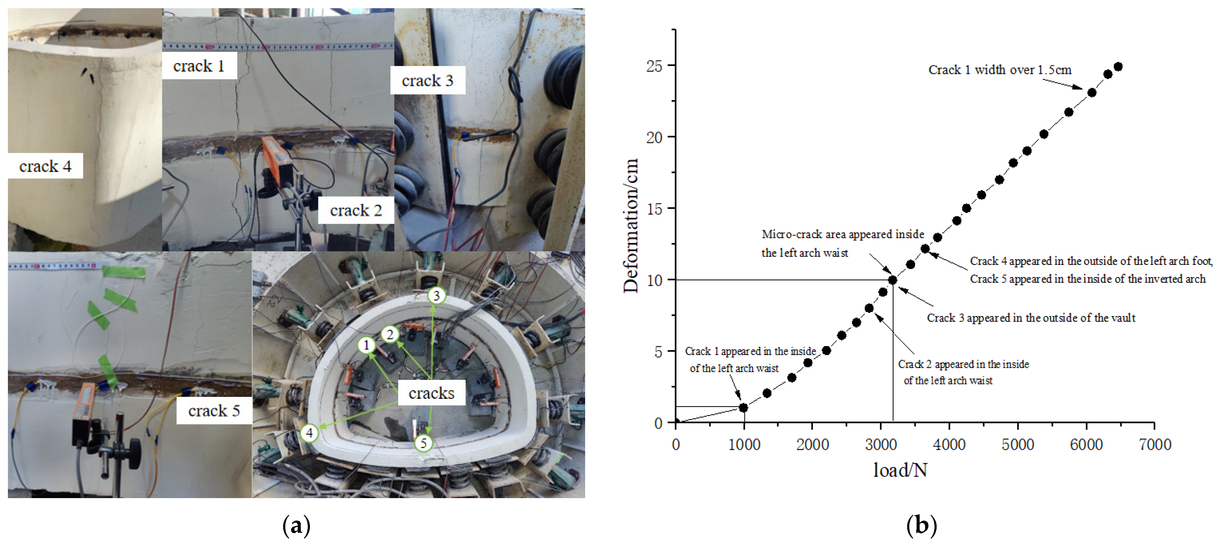
3.1. Analysis of Cracking Characteristics of Intact Lining

There were 5 main cracks in intact lining under the unsymmetrical load. Among them, there were 2 main through cracks on the inner surface of the lining in the unsymmetrical position. These were distributed along the longitudinal lining. The other 3 cracks were distributed on the outside of the left arch foot, the outside of the right spandrel and the inside of the inverted arch. The final shape and location distribution of lining cracks are shown in Figure 5.
As can be seen from Figure 5, with the increase in load, cracks appeared in specimen 1 in the order of arch inside the left arch waist → the outside of the vault → the outside of the left arch foot and the inside of the inverted arch. Among them, the inner crack of the left arch waist gradually developed along the axial direction of the lining, and the concentration area of short micro-cracks appeared around the main crack, which eventually led to the failure of the lining structure as a whole.
Combined with the changes in cracks, deformation and force shown in Figure 5b, it can be seen that the force process of the intact lining under unsymmetrical load was divided into three stages. Stage 1: elastic deformation occurred in the specimen, with the increase in load. The internal pores and micro-damages of the specimen were compacted, and no cracks appeared on the surface of the specimen. Stage 2: when the load reached 16.5% of the ultimate load, crack 1 appeared inside of the unsymmetrical position. After the crack appeared, the stiffness of the specimen decreased, and the deformation rate of the lining increased rapidly. With the increase in load, the stress of the steel bar at crack 1 increased compared with that before cracking, which restrained the propagation of crack 1, causing a new crack to appear in the unsymmetrical position. Stage 3: when the load reached 52.2% of the ultimate load, short and shallow micro-cracks appeared inside the unsymmetrical position. With the increase in load, the stress of reinforcement in the unsymmetrical position continued to increase, which inhibited the crack propagation and decreased the deformation rate. Cracks 3, 4, 5 began to appear in the vault both outside the left arch foot and inside the inverted arch. As the load continued to increase, the stress of the reinforcement in the in the unsymmetrical position reached the limit value, the inhibition ability to cracks and deformation was reduced. The deformation rate of the specimen began to rise, the opening amount of the main crack 1 exceeded 1.5 mm, and the specimen underwent accelerated failure and eventually lost its bearing capacity.

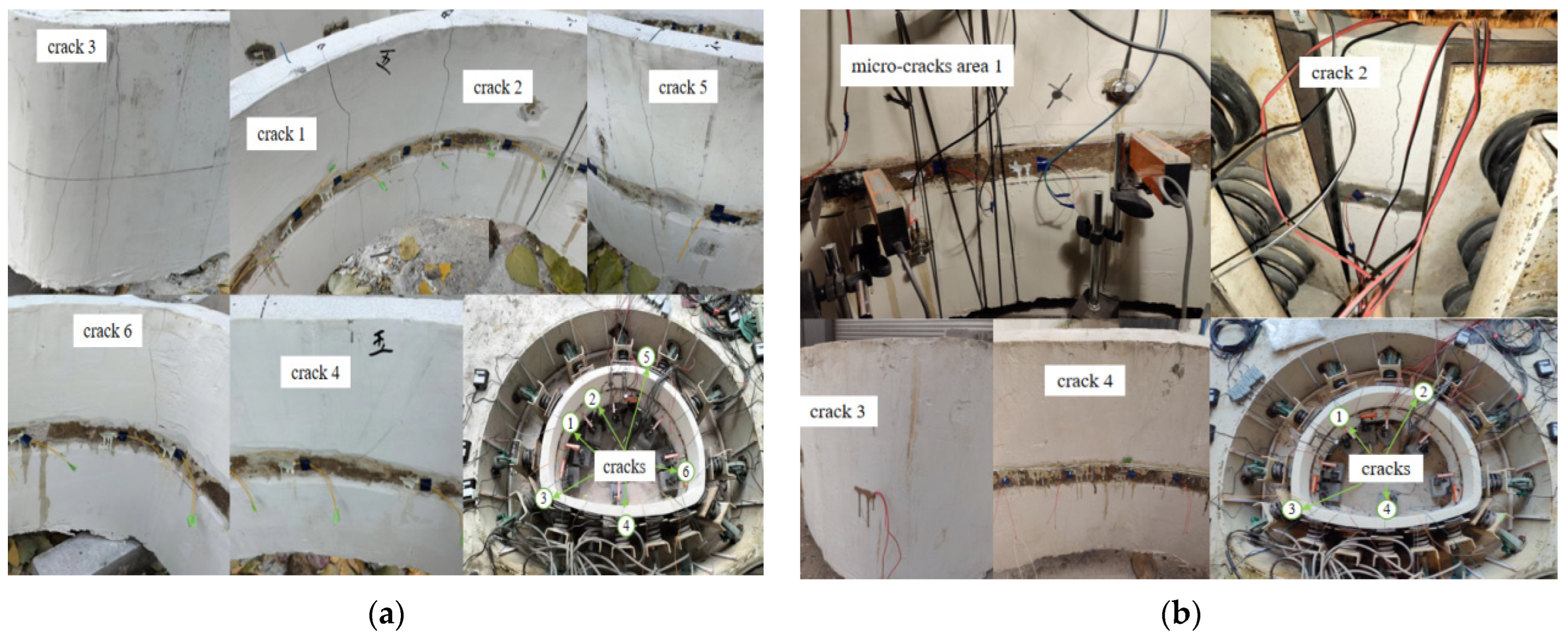
3.2. Influence of Different Positions of Existing Defects on Bearing Capacity and Deformation of Lining

Specimens 2 and 3 were analyzed to study the influence of different defect locations on the bearing capacity, deformation and cracking characteristics of lining structures with defect depth of h/3.
Specimen 2 (vault defect) produced a total of 6 main cracks when an unsymmetrical load was applied. Among them, there were 2 main through cracks on the inner surface of the lining in the unsymmetrical position, which were distributed along the lining lengthwise. The other 4 cracks were distributed on the outside of right spandrel, the outside of the left arch foot, the inside of the inverted arch and the inside of the right arch foot. The final morphology and location distribution of lining cracks are shown in Figure 6a.
Specimen 3 (arch waist defect) produced the main crack group under the unsymmetrical position and one crack outside the right spandrel. The final morphology and location distribution of lining cracks are shown in Figure 6b.
It can be seen from Figure 7a that with the increase in load, the order of cracks in specimen 2 was inside of the left arch waist → outside of the right spandrel and inside of the inverted arch → inside of the right arch foot. Since the existing defect in the vault, after the main crack occurred inside of the left arch waist, cracks began to occur near the existing defect area, but there was no short micro-cracks concentration area in the main crack area. The main cracks continued to spread, eventually leading to the overall failure of the lining structure.
It can be seen from Figure 7b that with the increase in load, the order of cracks in specimen 3 was the defect location of the left arch waist → the micro-cracks area in the left arch waist → outside of the right spandrel → outside of the left arch foot and the inside of the inverted arch. Since the existing defect at the unsymmetrical position, the lining cracks were mainly concentrated in the left arch waist. With the increase in load, crack concentration areas appeared around the main crack, which eventually led to the overall failure of the lining structure.
It can be seen from Figure 7 and Table 4 that under unsymmetrical load conditions, the initial cracking position of the lining occurred at the unsymmetrical position, regardless of the unknown existing defects. Except for the unsymmetrical position, the cracks mainly occurred in the vault, inverted arch and arch foot. Compared with intact lining, the ultimate bearing capacity of the vault defect and arch waist defect decreased by 14.2% and 21.3%, respectively, and the maximum deformation decreased by 44.6% and 50.6%, respectively. At the same time, compared with the intact lining, the initial cracking load of the vault defect and arch waist defect decreased by 33.1% and 73.0%, respectively. This indicates that the closer the existing defect is to the unsymmetrical position, the faster the initial cracking at the unsymmetrical position and the faster the lining instability will be. Although the radial deformation in unsymmetrical position of vault defect and arch waist defect were smaller than those of the intact lining, the radial deformation ratios in unsymmetrical position of each stage were basically the same, being concentrated in about 5%, 40% and 53%, respectively. This indicated that the radial deformation degree of lining cracking at each stage was basically the same under unsymmetrical load, and was not affected by the position of the existing defects.

4. Analysis of Fracture Evolution Characteristics of Unsymmetrical Lining Based on AE

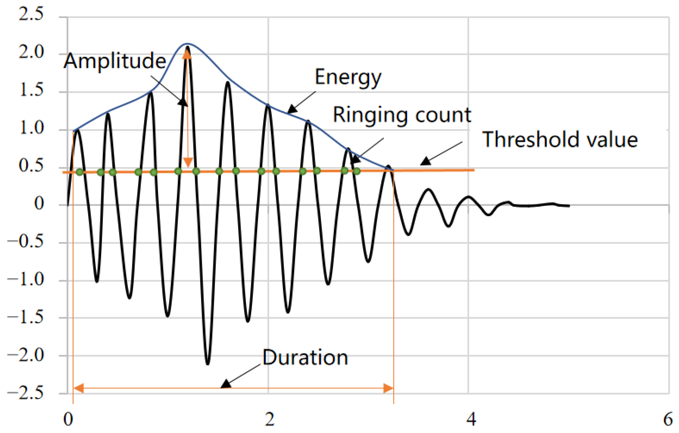
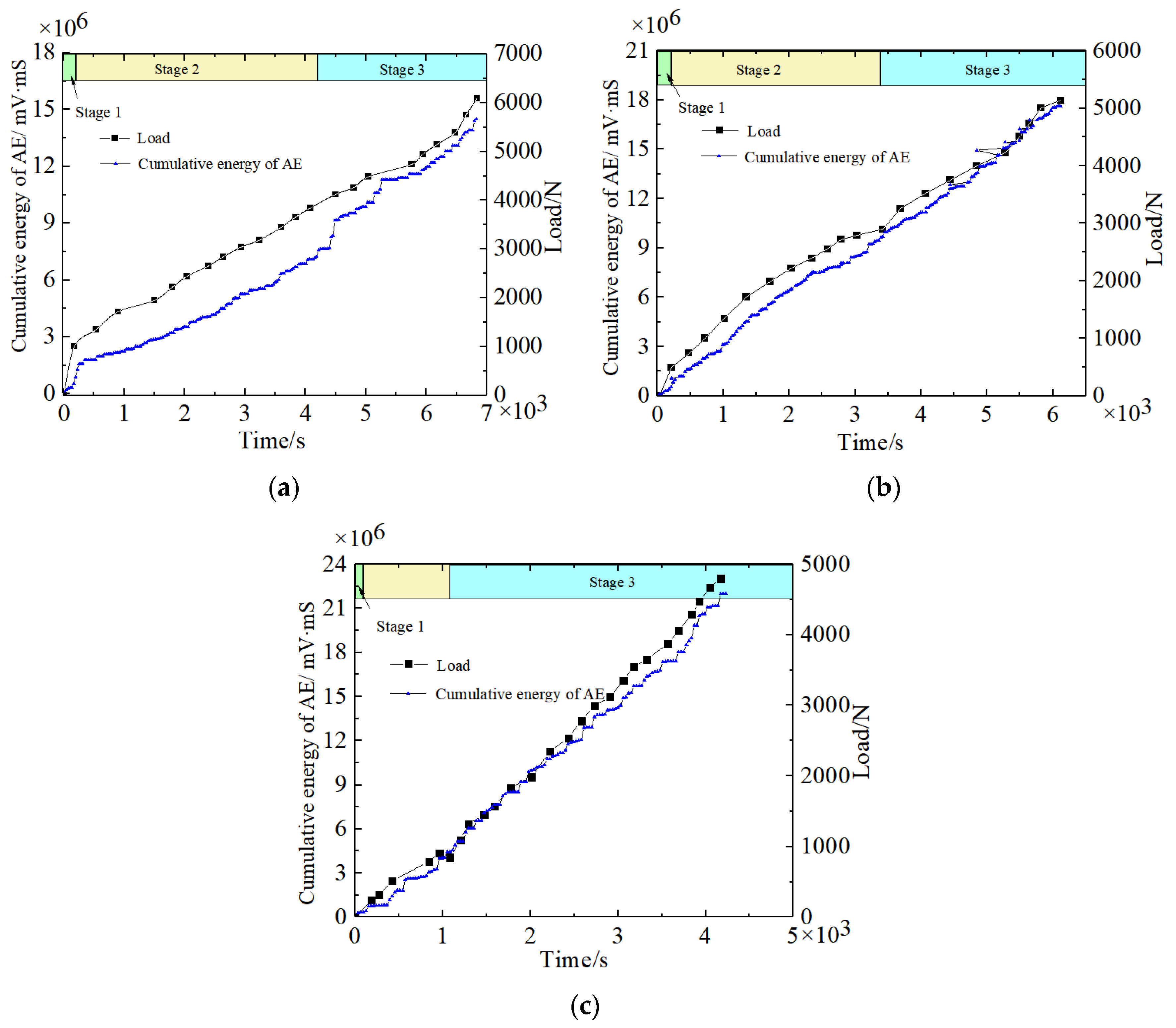
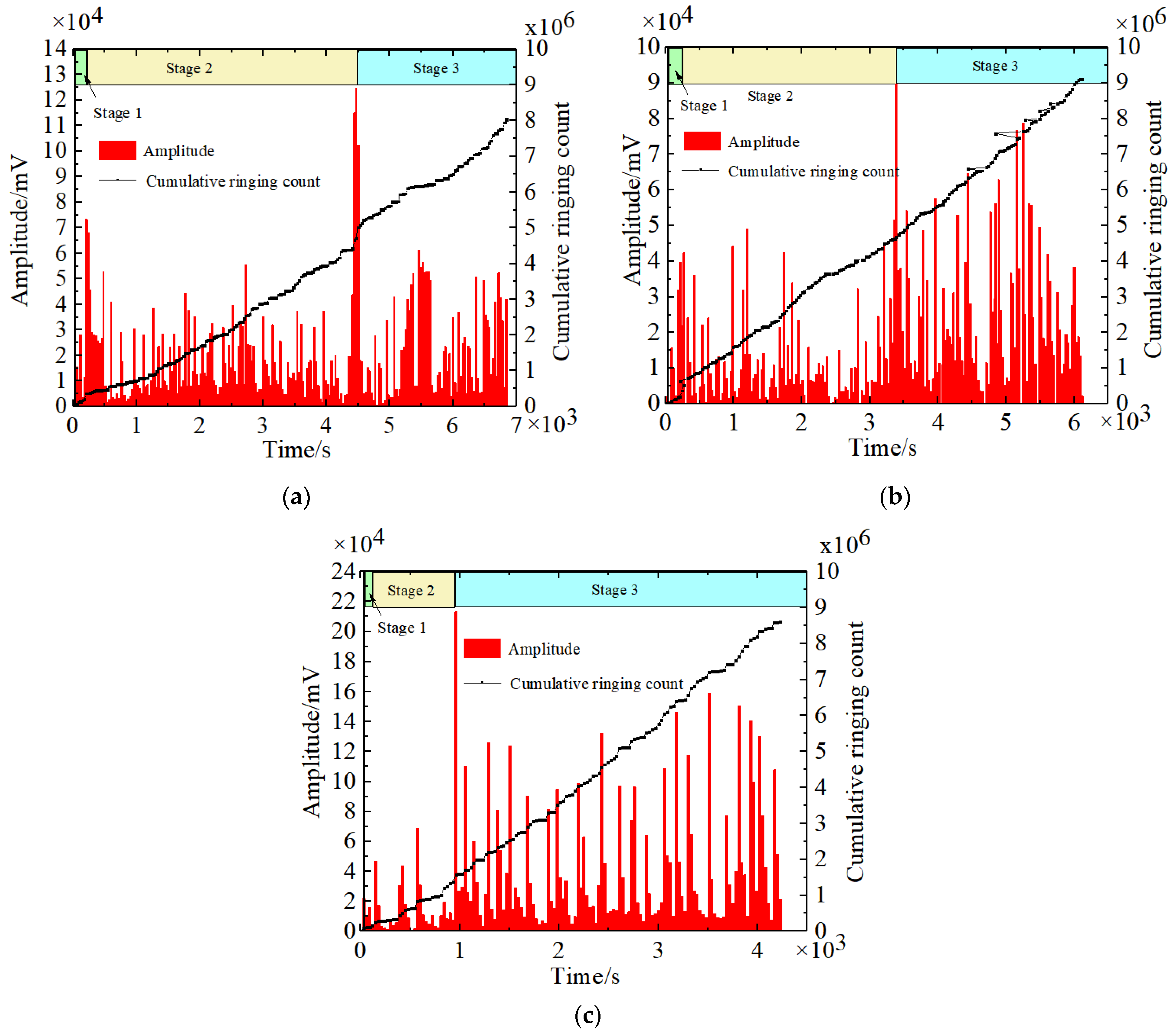
4.1. AE Test Results

The AE signal waveform of a damage event is shown in Figure 8, and it can be seen from the figure that the energy is the area under the envelope of the damage waveform, indicating the size of the damage. Amplitude is the peak value of the damage waveform, indicating the degree of damage. The ringing count is the number of times the damage waveform crosses the threshold value, indicating the active degree of damage inflicted. Therefore, the cumulative energy of AE, amplitude and cumulative ringing count were used to reflect the fracture evolution characteristics of the lining under unsymmetrical load.
It can be seen from Figure 9 and Figure 10 that the cumulative energy of AE is basically consistent with the change in lining load over time. The whole process of lining failure under unsymmetrical load can also be divided into three stages. Additionally, the time nodes of curve fluctuations in each stage are consistent, which further proves that the AE test results can effectively reflect the whole process of structural failure.
Stage 1: At this stage, the duration of specimen 1 lasted for 270 s, while specimens 2 and 3 were comparatively shortened by 14.8% and 44.4%, respectively. Compared with specimen 1, the amplitude of specimen 2 and specimen 3 decreased by 40.3% and 51.4%, the cumulative energy of AE decreased by 16.7% and 55.6%, and the cumulative ringing count decreased by 20.0% and 45.1%, respectively. The results show that the closer an existing defect is to the unsymmetrical position and the faster the initial cracking at the unsymmetrical position is, the smaller and less active the initial cracking damage of the crack will be.
Stage 2: This stage is the most important stage of the whole process of lining failure. The AE test results of three kinds of specimens accounted for 57.4%, 54.1% and 26.2% of the whole process of lining fracture, respectively. At this stage, the cracks of specimen 2 began to transfer to the existing defects of the vault, and the amplitude decreased by 26.7% compared with specimen 1. However, the growth rate of the cumulative energy of AE and cumulative ringing count increased by basically the same amount, indicating that the damage of specimen 2 decreased at this time, but the active degree of damage that occurred did not decrease and the crack expanded steadily. The cracks in specimen 3 continued to develop at the existing defect, the amplitude was 75.0% higher than that of specimen 1. However, the cumulative energy of AE and the cumulative ringing count were much smaller than that of specimen 1, indicating that the damage of the arch waist defect increased rapidly, the active degree of damage that occurred was not high, and the crack expansion was instantaneous. The closer the existing defect is to the unsymmetrical position, the faster the crack development and the shorter the main crack forming time will be.
Stage 3: Compared with the intact lining, the amplitude of the vault defect and arch waist defect lining increased significantly, the cumulative energy of AE was 35.7% and 42.9% higher, respectively, and the cumulative ringing count was basically the same. The results showed that the closer the existing defect is to the unsymmetrical position, the higher the degree of damage will be. However, the active degree of damage that occurred was not high.

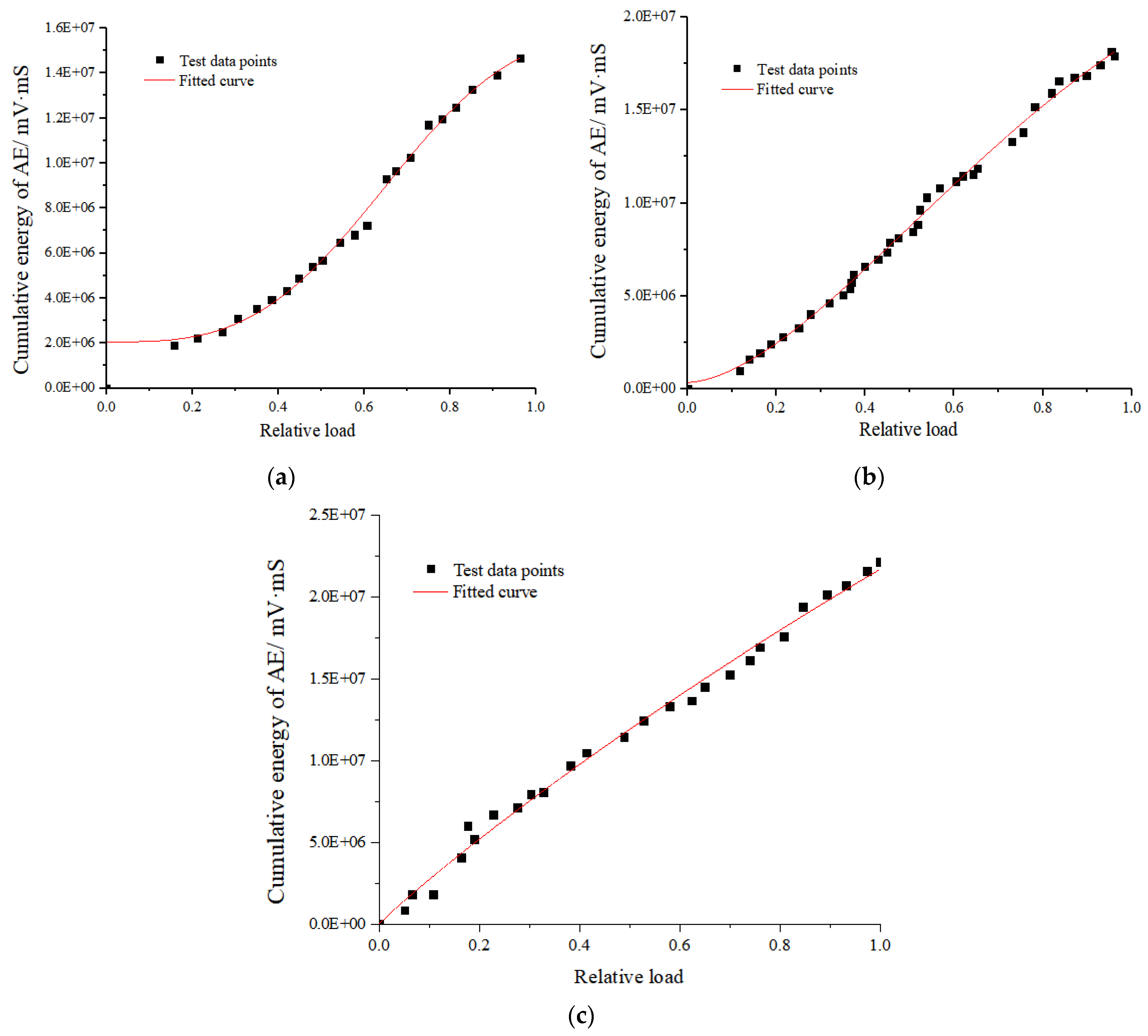
4.2. Fracture Evolution Model of Lining

It has been proved above that AE test results can effectively reflect the whole process of lining cracking from the microscale to the macroscale under unsymmetrical load. In addition, the energy of AE refers to the area under the envelope of the damage waveform, which is not the fracture energy in an intuitive sense. However, a larger energy of AE indicates that the waveform area above the threshold value is larger, which indirectly reflects the degree of structural damage. Therefore, this paper proposes the probability density function based on the cumulative energy of AE:
f V d V = d G / G 0
where V is the relative load borne by the lining, that is, the ratio of load borne by components and ultimate load; G is the sum of energy of AE from the beginning of damage to the current moment, that is, the cumulative energy of AE at the current moment; G0 is the sum of all energy of AE occurring when the lining reaches the peak load, that is, the cumulative energy of AE at the peak load.
The new probability density function can be obtained by dividing Equation (1) by dV:
f V = 1 G 0 d G d V
Integrating Equation (2) from the relative stress level 0 to 1:
0 1 f V d V = 0 G 0 d G / G 0 = 1
Then, the damage variable expression of the lining is:
D = 0 V f V d V = 0 V 1 G 0 d G d V
According to Formula (4), in order to establish the damage variable model with cumulative energy of AE as the variable, the functional relationship between the cumulative energy of AE and relative load should be found first.
The Weibull function is commonly used to describe the distribution of failure data of brittle materials. Therefore, the “S” Weibull function was used to fit the variation of cumulative energy of AE of the lining under unsymmetrical load. The fitting function was expressed as:
y = a ( a b ) exp ( ( k x ) d )
where a is the maximum value of cumulative energy of AE; b is the instantaneous energy value of lining cracking; k is the energy accumulation factor, the higher the value of k, the faster the accumulation of energy; and d is the comprehensive influence factor of energy.
It can be seen from Figure 11 and Table 5 that the curve has a high degree of fitting, and that the curves fitted to R2 were all greater than 0.95. This indicates that this function can effectively describe the relationship between cumulative energy of AE and relative load, namely:
G = X ( V ) = a ( a b ) exp ( ( k V ) d )
Meanwhile, it can be seen from the fitting results in Table 5 that, compared with specimen 1, the maximum cumulative energy of specimen 2 and 3 increased by 66.7% and 541.5%, the instantaneous energy value of lining cracking decreased by 61.7% and 73.3%, and the energy accumulation factor decreased by 47.5% and 70.15%, respectively. This is further proof that the closer the closer the existing defect is to the unsymmetrical position, the faster the initial cracking, the lower the degree of initial cracking damage, the shorter the main crack forming time, and the higher the degree of damage during lining failure will be, but that a less active degree of damage will occur during the whole cracking process.
Formula (6) is substituted into Formula (4) to obtain the expression of the damage variable based on the cumulative energy of AE:
D = a ( a b ) exp ( ( k V ) d ) / G 0
The relationship between the lining damage variable and the deformation calculated by Equation (7) is shown in Figure 12.
It can be seen from Figure 12 that the damage velocity of specimen 2 and 3 is significantly faster than that of specimen 1. The evolution stage of lining damage was delineated based on the initial crack damage range of specimen 1, which was 0.04. As the benchmarks, the deformation was 1.21 cm, the main crack development damage was 0.35, and the deformation was 9.96 cm. When the damage of specimen 2 and specimen 3 reached 0.04 and 0.35, the deformation was advanced by 58.3%, 75.0%, 40.2% and 50.6%, respectively. This indicated the following: the closer the existing defects are to the unsymmetrical position, the faster the cracking at the unsymmetrical position will be. The faster the lining is, the more it becomes unstable. When the damage exceeds 0.6, the damage variable curves of specimen 2 and specimen 3 basically coincide, indicating that the existing defects in different positions only affect the speed of damage evolution during crack cracking and development, and do not affect the damage rate of the structure after crack expansion and forming.

5. Conclusions

Through similar model tests, the deformation characteristics and crack development characteristics of different existing defect linings under unsymmetrical load were investigated. Based on AE technology, the fracture evolution characteristics of lining under unsymmetrical load was analyzed. Th results showed that:
(1)
The failure process of the intact lining under unsymmetrical load has three stages: “initial crack cracking at the unsymmetrical position → development and formation of main crack → specimen cracking failure”. The sequence of crack development is as follows: inside of the arch waist at the unsymmetrical load → the outside of the vault → the outside of the arch foot on the unsymmetrical side and the inside of the inverted arch. The load ratio of initial crack cracking is 16.5%, and the load ratio of main crack development and formation is 52.2%. Once the main crack is formed, the specimen enters a stage of rapid failure.
(2)
The initial cracking location of the lining under unsymmetrical load is independent of the location of existing defects, and all cracks occur at the unsymmetrical position. Other cracks are mainly distributed at the vault, inverted arch and arch foot.
(3)
The closer the existing defects are to the unsymmetrical position, the faster the initial cracking at the unsymmetrical position and faster the lining instability will be. Compared with intact lining, the ultimate bearing capacity of vault defect and arch waist defect decreased by 14.2% and 21.3%, respectively, and the maximum deformation decreased by 44.6% and 50.6%, respectively. The radial deformation degree in an unsymmetrical position at each stage is basically the same under unsymmetrical load and is not affected by the location of existing defects. The proportion of radial deformation in each stage is concentrated in 5%, 40% and 53%, respectively.
(4)
The AE technology can effectively reflect the three stage characteristics of lining fracture evolution under unsymmetrical load. The closer the existing defect is to the unsymmetrical position, the faster the initial cracking, the lower the degree of initial cracking damage, the shorter the main crack forming time, the higher the degree of damage during lining failure will be, but the less active a degree of damage occurs during the whole cracking process.
(5)
The fracture evolution model of unsymmetrical lining was derived based on the cumulative energy of AE, and the quantitative relationship between the damage variables of unsymmetrical lining and the deformation of lining was established. Compared with the intact lining, the location of existing defects only affects the damage evolution rate during crack cracking and development but does not affect the damage rate of the structure after crack propagation.
(6)
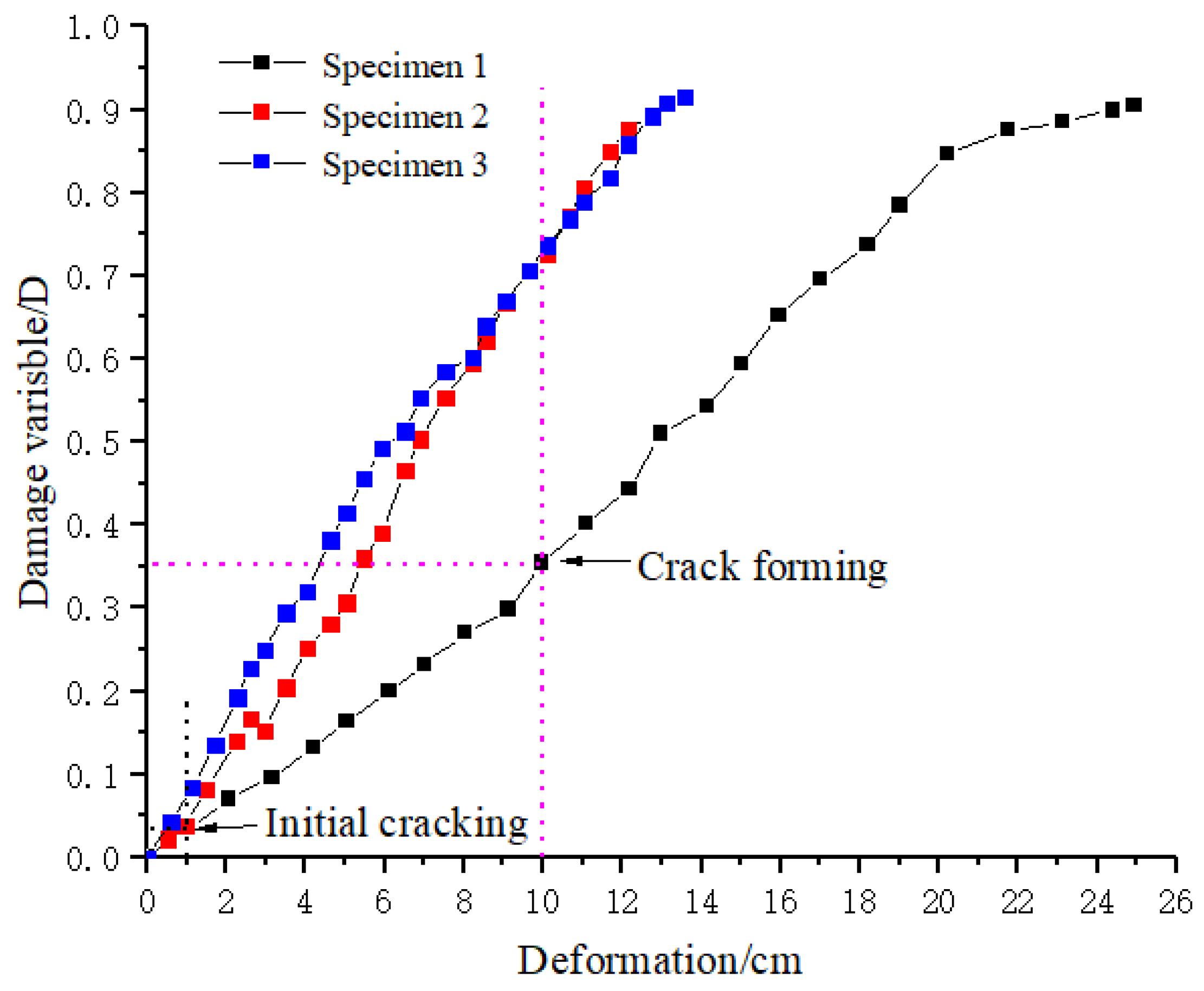
Under the unsymmetrical load, when the radial deformation in unsymmetrical position of the complete lining reaches 1.21 cm and 9.96 cm, the fracture degree of the lining reaches 0.04 and 0.35. At this time, the tunnel lining should be reinforced in time to ensure the normal use of the tunnel. However, when the vault defect lining and arch waist defect lining reach the fracture degree, the deformation is 58.3%, 75.0% 40.2%, and 50.6% earlier than that of the complete lining. The results provide guidance for determining the damage degree of a biased tunnel with existing defects in real engineering and when to adopt reinforcement.

Author Contributions

Conceptualization, J.L. and F.X.; methodology, J.L. and F.X.; validation, J.L. and X.Z.; formal analysis, J.L.; investigation, J.L.; resources, B.L. and T.B.; data curation, J.L., Q.T. and T.B.; writing—original draft preparation, J.L.; writing—review and editing, J.L. and F.X.; visualization, J.L.; supervision, F.X.; project administration, F.X. All authors have read and agreed to the published version of the manuscript.

Funding

This research was funded by the authors gratefully acknowledge the financial support offered by National Natural Science Foundation of China, grant number: 52078311, 51991395; Shenzhen Science and Technology program, grant number: KQTD 20180412181337494; Natural Science Foundation of Hebei Province, grant number: E2021210099; Project of Science and Technology Research and Development Program of China Railway Corporation, grant number: N2022G033.

Institutional Review Board Statement

Not applicable.

Informed Consent Statement

Not applicable.

Data Availability Statement

The data presented in this study are available on request from the corresponding author.

Conflicts of Interest

The authors declare no conflict of interest.

References

  1. Lei, M.F.; Peng, L.M.; Shi, C.H. Damage mechanism and evolution law of mechanical property of tunnel structure suffering sulfate ambient. J. Cent. South Univ. 2012, 43, 4865–4872. [Google Scholar]
  2. Zheng, X.Y.; Wang, Y.R.; Zhang, S.Q.; Xu, F.; Zhu, X.P.; Jiang, X.; Zhou, L.; Shen, Y.; Chen, Q.; Yan, Z.G.; et al. Research progress of the thermophysical and mechanical properties of concrete subjected to freeze-thaw cycles. Constr. Build. Mater. 2022, 330, 127254. [Google Scholar] [CrossRef]
  3. Tan, Z.S.; Zeng, C.; Li, J.; Du, C.W.; Zhang, P. Model test investigation on the mechanical characteristics of support structure of subsea tunnels. China Civ. Eng. J. 2011, 44, 99–105. [Google Scholar]
  4. Zhao, L.H.; Huang, F.; Sun, Q.H.; Xu, Z.M.; Luo, W. Rock pressure of unsymmetrical shallow rectangular tunnel based on upper bound limit analysis method. J. Cent. South Univ. 2014, 45, 3093–3103. [Google Scholar]
  5. Du, J.M.; Fang, Q.; Hai, L.; Mai, H.Y.; Wang, G. Calculation method for surrounding rock pressure of shallow tunnel with asymmetrical pressure of variable slopes. J. Cent. South Univ. 2021, 52, 4088–4098. [Google Scholar]
  6. Liu, X.R.; Chen, H.J.; Liu, K.; He, C.M. Model test and stress distribution law of unsymmetrical loading tunnel in bedding rock mass. Arab. J. Geosci. 2017, 10, 184. [Google Scholar] [CrossRef]
  7. She, J.; He, C.; Wang, B.; Wang, Y. Study on Effect of Cavities behind Linings on Bearing Capacity of Tunnel Structure by Model Test. J. Highw. Transp. Res. Dev. 2008, 1, 104–110. [Google Scholar]
  8. He, C.; Tang, Z.C.; Wang, B.; She, J. Research on effect of inner surface reinforcing on structure bearing capacity by model test in defective tunnel. Rock Soil Mech. 2009, 30, 406–412. [Google Scholar]
  9. Liu, X.Z.; Liu, W.Y.; Sang, Y.L.; Gu, Y.C. Experiment on the influence of cracking characteristics under unsymmetrical load on stresses or forces in tunnel lining. China Civ. Eng. J. 2015, 48, 119–128. [Google Scholar]
  10. Liu, X.Z.; Duan, J.M.; Guo, Q.K. Analysis on Damage Evolution of Highway Tunnel Lining under Lateral Load. Chin. J. Undergr. Space Eng. 2021, 17, 1529–1536. [Google Scholar]
  11. Lei, M.F.; Peng, L.M.; Shi, C.H.; Wang, L.C.; Liu, Z.C. Calculation of the surrounding rock pressure on a shallow buried tunnel using linear and nonlinear failure criteria. Autom. Constr. 2014, 37, 191–195. [Google Scholar] [CrossRef]
  12. Lei, M.F.; Peng, L.M.; Shi, C.H. Model test to investigate the failure mechanisms and lining stress characteristics of shallow buried tunnels under unsymmetrical loading. Tunn. Undergr. Space Technol. 2015, 46, 64–75. [Google Scholar] [CrossRef]
  13. Zhang, Z.G.; Jiang, Y.J.; Liu, M.; Dong, J.F. Rock pressure of shallow unsymmetrical-loading tunnels considering the cohesion and earthquake action. J. China Univ. Min. Technol. 2018, 47, 780–790. [Google Scholar]
  14. Li, J.W.; Xu, F.; Wang, T.M.; Shi, S.T. Research on the Evolution of Shield Segment Cracks Based on Acoustic Emission and CMOD. Materials 2022, 15, 5829. [Google Scholar] [CrossRef] [PubMed]
  15. Amedeo, M.; Gianni, N.; Alberto, C. AE monitoring of a concrete arch road tunnel: Damage evolution and localization. Eng. Fract. Mech. 2019, 210, 279–287. [Google Scholar]
  16. Triantis, D.; Loukidis, A.; Stavrakas, I.; Pasiou, E.D.; Kourkoulis, S.K. Attenuation of the Acoustic Activity in Cement Beams under Constant Bending Load Closely Approaching the Fracture Load. Foundations 2022, 2, 590–606. [Google Scholar] [CrossRef]
  17. Efe, S.; Amir, G.; Ninel, A. Study of fracture evolution in FRP-strengthened reinforced concrete beam under cyclic load by acoustic emission technique: An integrated mechanical-acoustic energy approach. Constr. Build. Mater. 2015, 95, 832–841. [Google Scholar]
  18. Yu, J. Study on the influence of stress distribution law by lining crack in highway tunnel. China Civ. Eng. J. 2017, 50, 70–75. [Google Scholar]
  19. Liu, X.Z.; Wang, X.L.; He, B.G.; Sang, Y.L. Model Test of Cracked Tunnel Lining Reinforced with Umbrella Arch Based on Secondary Loading. J. Sichuan Univ. 2015, 47, 21–28. [Google Scholar]
  20. Li, J.W.; Xu, F.; Wang, B.; Gao, Y. Influence of concrete aggregate particle size on acoustic emission detection. J. Shangdong Univ. 2021, 51, 7. [Google Scholar]
Figure 1. Lining horizontal loading model test device.
Sustainability 15 09531 g001
Figure 2. Bias loading method.
Sustainability 15 09531 g002
Figure 3. Layout diagram of displacement meter.
Sustainability 15 09531 g003
Figure 4. Schematic diagram of AE sensor layout.
Sustainability 15 09531 g004
Figure 5. Cracking characteristics of intact lining: (a) schematic diagram of intact lining cracking; (b) schematic diagram of intact lining cracking.
Sustainability 15 09531 g005
Figure 6. Lining cracking at different defect locations: (a) vault defect lining; (b) arch waist defect lining.
Sustainability 15 09531 g006
Figure 7. Cracking characteristics of lining at different defect locations: (a) vault defect lining; (b) arch waist defect lining.
Sustainability 15 09531 g007
Figure 8. Waveform of damage acquisition.
Sustainability 15 09531 g008
Figure 9. Relationship between cumulative energy of AE and load: (a) Specimen 1; (b) Specimen 2; (c) Specimen 3.
Sustainability 15 09531 g009
Figure 10. Amplitude and ringing count collected results: (a) Specimen 1; (b) Specimen 2; (c) Specimen 3.
Sustainability 15 09531 g010
Figure 11. Fitting curve of cumulative energy and relative load: (a) Specimen 1; (b) Specimen 2; (c) Specimen 3.
Sustainability 15 09531 g011
Figure 12. Relation between damage variable and lining deformation.
Sustainability 15 09531 g012
Table 1. Relevant parameter similarity ratio.
Related ParametersSimilarity Ratio
Geometric Dimensioning L (m)1:10
Load N (N)1:1820
Formation Resistance Coefficient K (MPa/m)1:1.82
Stress σ (MPa)1:18.2
Elasticity Modulus E (MPa)1:18.2
Strain ε 1:1
Poisson Ratio μ 1:1
Displacement δ (cm)1:10
Table 2. Mix ratio of similar materials.
Required MaterialsCementRiver SandLimestoneWater
Mix Ratio17.70.61.75
Table 3. Model conditions of damaged lining.
Test ConditionsDefects
LocationDepth
Specimen 1Intact Lining--
Specimen 2Defective LiningVaulth/3
Specimen 3Arch Waisth/3
Schematic DiagramSustainability 15 09531 i001
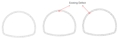
Specimen 1      Specimen 2      Specimen 3
Note: h is the lining thickness.
Table 4. Deformation and load characteristics of different defective lining cracking at different stages under unsymmetrical load.
Initial CrackingFracture DevelopmentLate FractureUltimate Load (N)Ultimate Deformation (cm)
Specimen 1LocationInside of the the left arch waistInside of the left arch waist and outside of the vaultOutside of the left arch foot, inside of the inverted arch609324.9
Load (N)100831823746
Load Ratio16.5%52.2%61.4%
Deformation (cm)1.219.9613.08
Deformation Ratio4.8%40.0%52.5%
Specimen 2LocationInside of the the left arch waistOutside of the vault, inside of the inverted arch and outside of the the left arch footInside of the right arch foot523013.8
Load (N)67426983079
Load Ratio12.9%51.6%58.9%
Deformation (cm)0.625.547.23
Deformation Ratio4.5%40.1%52.4%
Specimen 3LocationInside of the the left arch waistInside of the the left arch waist, outside of the the right spandrelOutside of the the left arch foot, inside of the inverted arch479712.3
Load (N)27214712267
Load Ratio5.6%30.7%47.3%
Deformation (cm)0.584.956.62
Deformation Ratio4.7%40.2%53.8%
Table 5. Curve fitting results.
SpecimenabdkR2
11.59 × 1072.06 × 1063.181.370.99
22.62 × 1070.76 × 1061.671.140.99
31.02 × 1070.55 × 1060.950.220.99
Disclaimer/Publisher’s Note: The statements, opinions and data contained in all publications are solely those of the individual author(s) and contributor(s) and not of MDPI and/or the editor(s). MDPI and/or the editor(s) disclaim responsibility for any injury to people or property resulting from any ideas, methods, instructions or products referred to in the content.

