Article

Study on Mechanical Calculation Model of Arch Ring in Freestanding Stone Cave-Dwelling

1
School of Architectural Engineering, Yan’an University, Yan’an 716000, China
2
Department of Basic Construction, Yan’an University, Yan’an 716000, China
*
Author to whom correspondence should be addressed.
Sustainability 2023, 15(12), 9545; https://doi.org/10.3390/su15129545
Submission received: 14 April 2023 / Revised: 28 May 2023 / Accepted: 9 June 2023 / Published: 14 June 2023
(This article belongs to the Section Sustainable Engineering and Science)

Abstract

:
The freestanding stone cave-dwelling is a kind of arched and sheltered house built with stones in the Loess Plateau region of northwest China. Amazingly, before construction, this kind of cave-dwelling was not formally calculated and designed in theory, but only built on the experience passed down by predecessors. The arch ring is the main load-bearing component of the freestanding stone cave-dwelling, through which the upper loads are transmitted to the legs on the left and right sides of the cave-dwelling and then to the foundations. Therefore, it is a prerequisite to ensure the safety of cave dwellings by adopting a reasonable and accurate mechanical calculation model for the arch ring of a stone cave-dwelling to reveal the distribution of internal forces in the arch ring and scientifically design the arch ring accordingly. Three mechanical calculation models (structural calculation diagrams) are adopted for the arch ring of stone cave-dwelling, namely, hingeless arch, two-hinged arch, and three-hinged arch. Based on the force equilibrium and the force method from the structure mechanics, the formulae for calculating the internal force of the stone arch ring under these three different mechanical calculation models are derived respectively. The mechanical calculation results of three calculation models are compared and analyzed to clarify the difference and rationality of the stress results of the arch ring under the three mechanical calculation models and the degree of influence on the force of the lower cave-dwelling leg members. Lastly, in accordance with the internal force calculation results, the calculation formulae for the design of the arch ring thickness are proposed. The study shows that the hingeless arch and two-hinged arch models are more consistent with the actual failure characteristics, two-hinged arch calculation model is safer, more accu-rate, and more reliable than the hingeless arch calculation model when it is used in the mechanical analysis of circular arc arch ring. The findings are intended to serve as theoretical references for the design and construction, protection and reinforcement, and sustainable development and inheritance of cave dwellings in the future.

1. Introduction

The freestanding stone cave-dwelling is a kind of earth-sheltered arched house, which is formed by directly building an arch ring with stones on the flat land, backfilling a certain thickness of loess at the top, and compacting it, as shown in Figure 1 [1]. Its upper part is covered with loess, which can make use of the thermal insulation function of soil, so the stone cave-dwelling is known as a natural energy-saving ecological residence, with good sustainable development prospects. Compared with loess cave dwellings, freestanding stone cave dwellings are safer, more reliable, and have better durability. In addition, their construction is based on local materials, their cost is low, and they have the advantages of being warm in winter and cool in summer. This type of cave-dwelling has sprung up in the rural areas of northern Shaanxi and has become the mainstream residential form for the inhabitants of China Loess Plateau due to these advantages. However, the construction of freestanding stone cave dwellings was not preceded by force analysis and structural design, and construction relied entirely on the experience of the builders, so there are often safety hazards in the existing cave dwelling structures, such as arch ring cracks, bearing capacity reduction and other structural damages [2]. Therefore, the in-depth study of the mechanics of the freestanding stone cave-dwelling structures, especially the mechanical calculation model of the arch ring in the stone cave-dwelling, is a crucial step to ensure the safety and scientific design of the stone cave-dwelling structure. This has important scientific value and practical significance for the future inheritance, development, and conservation of these sustainable greenhouses [3].
The stone cave-dwelling is classified as an earth-sheltered building according to its construction characteristics. Earth-sheltered buildings can use the thermal performance of raw materials to achieve thermal insulation, thus saving energy consumption and preserving the ecological environment, which has been widely recognized by international scholars [4,5,6]. International scholars have carried out a number of studies on the thermal performance [7,8], architectural design [4,9,10], and construction technology of earth-sheltered buildings [11,12], which provides a reliable basis and technical data for further innovation, design, and construction of earth-sheltered buildings, and gives designers and builders of earth-sheltered buildings a great deal of inspiration and experience. Cave dwellings, as distinctive Chinese buildings, have attracted quite a few scholars in China to make a series of research on them. Their researches mainly focus on the construction principle [13,14,15], force characteristics [16,17,18], seismic performance [19,20,21,22], thermal insulation and energy conservation [23,24,25], stability analysis [26,27,28,29,30,31,32], and reinforcement and protection measures [33,34,35,36] for loess cliff-side cave dwellings and pit-type cave dwellings, while there are few researches on freestanding stone cave dwellings. Combining with the actual earthquake damage and numerical simulation experiment, Wang Feijian et al. [37] put forward that the ratio of vertical displacement of the arch vault to arch vector height should be taken as the damage index of independent cave dwellings under seismic motion. Yan Yuemei et al. [38,39] used a three-hinged arch for masonry cave-dwelling and performed force analysis of the stone arch ring, but the axis of the arch ring was selected as a rational arch axis (suspension chain line), which differs from the circular arc arch mostly used in existing cave dwellings. Zhang Yuxiang [40] et al. analyzed the force situation of adobe masonry half-exposed and half-concealed cave-dwelling, and only the calculation of the reaction force of the vault and the feet of the arch was carried out by the method of “equivalent three-hinged arch”, but the section analysis was not explored. Huang Caihua [41] et al. conducted a stress analysis of a semi-circular arch shaft cave-dwelling, and the calculation model adopted was a two-hinged arch. By consulting the static calculation manual, the internal force coefficients of the arch under different loads were listed, and the internal force results were determined after superposition, which was relatively cumbersome to calculate. In the aforementioned literature, the feet of the arches were simulated as fixed-hinged supports, and the calculation model adopted two-hinged arches or three-hinged arches, which did not deduce the unified formulae for the internal force calculation of the arch ring.
The composition of a freestanding stone cave-dwelling is presented in Figure 2. which shows that this structure can be simplified into two parts: one part is the upper arch ring member, which mainly bears the uniform load and dead weight of the upper structure, and is a flexible member; the other part is the lower cave-dwelling members, which mainly bears the vertical load from the upper structure, and also bears the horizontal thrust, so this part is a compression member. In most cases, freestanding stone cave dwellings are connected by multiple single-hole caves. The middle cave-dwelling legs are balanced by the thrust from the arch ring supports on both sides and only bear the vertical support reaction force of the arch ring at the foot of the arch, which are axial compression members; However, as for the cave-dwelling legs on the side, besides bearing the vertical bearing reaction force at the feet of the arch ring, they also have to bear the horizontal push. Therefore, the side leg is considered a beam-column. In conclusion, the mechanical analysis of the arch ring in the upper part of the cave-dwelling is the focus and primary problem in the force research of the freestanding cave-dwelling structure. The accuracy and rationality of the arch ring calculation model will directly affect the safety of the structural design of freestanding stone cave dwellings.
In order to scientifically and effectively reveal the internal forces distribution in different sections of the arch ring of freestanding stone cave dwellings, and to clarify the difference in force calculation results of the arch ring of freestanding cave dwellings under different mechanical calculation models, the arch ring of stone cave-dwelling is simplified into three calculation models: hingeless arch, two-hinged arch, and three-hinged arch. The unified formulae for calculating the internal force of arc arch rings in stone cave-dwelling are deduced according to the force method, which is a classical solution method in structural mechanics [42,43]. And the mechanical calculation results of the three calculation models are compared and analyzed to verify the rationality and accuracy of the three calculation diagrams and the degree of safety influence on the structural forces of the lower cave-dwelling legs. Finally, based on the results of internal force calculation, the calculation formulae for determining the thickness of the arch ring of cave-dwelling are put forward. The study aims to provide some theoretical basis for the safety design, construction, and conservation of freestanding cave dwellings, which is conducive to the sustainable development and inheritance of cave dwellings.

2. Research Methodology

2.1. Basic Hypotheses Adopted in Calculation Model of Freestanding Stone Cave-Dwelling

In view of the structural characteristics of the freestanding cave dwellings, the assumptions used in establishing the calculation model are as follows:
1.
Freestanding cave dwellings are generally connected by multiple spans. As the arch rings are subjected to basically the same forces per span, a single-span arch ring is taken for the sake of simplicity of analysis.
2.
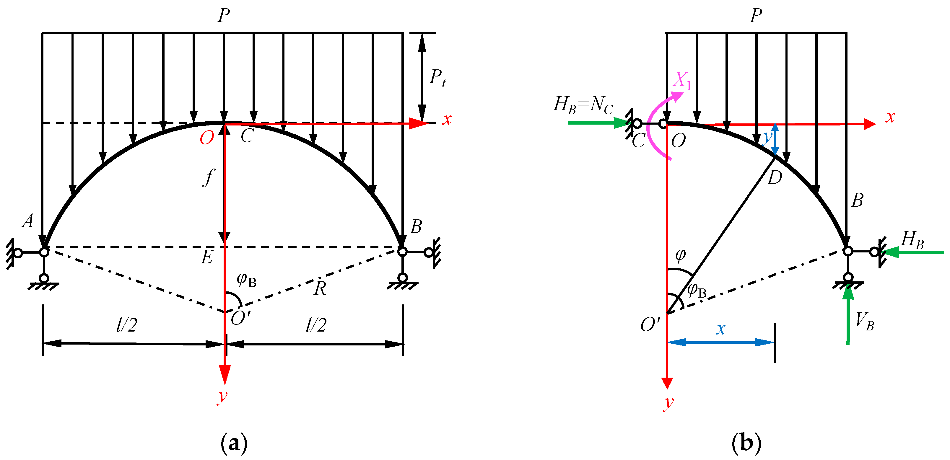
The arch axis curve of the arch ring has multiple forms, such as parabola, catenary and circular arc, etc. Here, the axis of the arch ring of the stone cave-dwelling is simplified as an equivalent cross-sectional circular arc. If the coordinate origin O is set at the vault of the arch, to the right as the x-axis, down as the y-axis, see Figure 2. Then the axis equation of the circular arc arch ring is expressed as:
x 2 + y R 2 = R 2
The radius R of the axis of the circular arc arch should satisfy the following equation:
R 2 = l 2 2 + R f 2
From Formula (2), it can be derived that:
R = l 2 + 4 f 2 8 f
In which, R is the radius of the circular arc arch ring axis; l is the span length of the arch ring axis; f is the arch height.
The φB is calculated as:
sin φ B = l 2 R cos φ B = R f R
As shown in Figure 2, the relationship between the rectangular coordinates and any central angle φ is:
x = R sin φ y = R R cos φ
3.
Normally, when f/l > 0.2, only the effect of bending deformation is considered, and the effects of shear deformation and axial deformation are not taken into account [42].
4.
It can be seen from Figure 2 that the loads on the freestanding stone cave-dwelling are mainly the self-weight of the arch ring, the self-weight of the fill, and the live load on the roof. The filling roof is regarded as a horizontal surface; the live load is considered to be uniformly distributed; the arch ring is assumed to be equally thick; and bending stiffness EI is constant. Then the load concentration P at any section of the arch ring is [39]:
P = P t + γ 2 y = γ 1 h 1 + γ 2 h 2 + γ 2 y + ψ q
in Formula (6), Pt is the vertical uniformly distributed load, Pt = γ1h1 + γ2h2 + ψq; γ1 and γ2 are the weight of the arch ring and the weight of the overburden (covering soil); h1 and h2 are the thickness of the arch ring and the thickness of the overburden on top of the arch ring; y is the longitudinal coordinate of the axis of the arch ring (see Figure 2 for the setting of the coordinate axis); ψ is the combined value coefficient of live load, which is generally taken as 0.7; q is the live load of the roof, which is taken as 2.0 kN/m2.

2.2. Derivation of Force Calculation Formula for Circular Arch Ring under the Calculation Model of Hingeless Arch

If we consider the bending moment that the arch ring is subjected to at the arch foot, the arch foot can be simulated as a fixed support and the arch ring of a freestanding stone cave-dwelling can be simplified as a symmetrical elastic-plastic fixed hingeless arch, whose force calculation model is shown in Figure 3a.

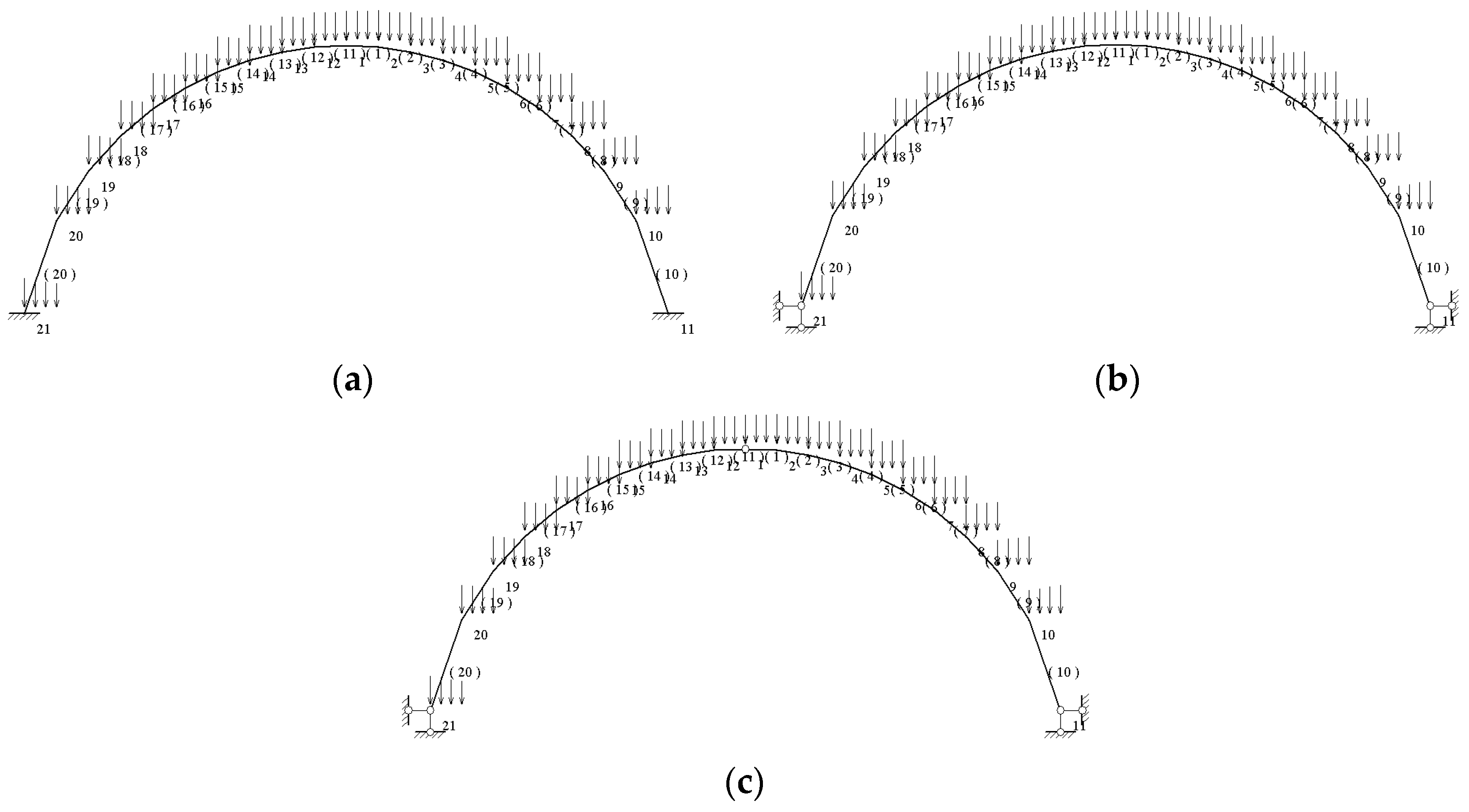
2.2.1. Selection of Basic System and Equation of Force Method

Hingeless arch belongs to a third order statically indeterminate structure. When calculating by force method, the basic structure of force method is cantilevering curved beam, and the basic system adopted is shown in Figure 3b. The unknown force system of the arch vault mainly includes unknown bending moment X1, unknown axial force X2, and unknown shear force X3. Because the structural load is symmetrically distributed, so the unknown value X3 = 0.
The equation of force method is:
δ 11 X 1 + δ 12 X 2 + Δ 1 P = 0 δ 21 X 1 + δ 22 X 2 + Δ 2 P = 0
in the above equation, δ11, δ12, δ21 and δ22 are all coefficients in the force method, Δ1P and Δ2P are the free terms in the force method.

2.2.2. Calculation of Force Method Coefficient and Free Term

The internal force calculation results of the cantilever curved beam under the action of X1 = 1 are as follows:
M 1 ¯ = 1 M 2 ¯ = y
here, the bending moment is positive with internal tension.
The force method coefficient is calculated as follows:
E I δ 11 = M 1 ¯ 2 d s = 2 0 φ B R d φ = 2 R φ B = a 1 R
E I δ 12 = M 1 ¯ M 2 ¯ d s = 1 y d s = 2 0 φ B R R cos φ R d φ = 2 R 2 φ B sin φ B = a 2 R 2
E I δ 22 = M 2 ¯ 2 d s = y 2 d s = 2 0 φ B R R cos φ 2 R d φ = 2 R 3 3 2 φ B 2 sin φ B + 1 4 sin 2 φ B = a 3 R 3
where
a 1 = 2 φ B a 2 = 2 φ B sin φ B a 3 = 3 φ B 4 sin φ B + 1 2 sin 2 φ B
The moment equation MP1(x) for the section of the basic structure at a distance x from the point O under the load P is:
M P 1 x = P t 2 x 2 x 0 x γ 2 y d x - 0 x x γ 2 y d x = P t 2 R 2 sin 2 φ γ 2 R sin φ 0 φ R R cos φ d R sin φ + γ 2 0 φ R sin φ R R cos φ d R sin φ = P t 2 R 2 sin 2 φ γ 2 R 3 sin φ sin φ φ 2 + 1 4 sin 2 φ + γ 2 R 3 1 2 sin 2 φ + 1 3 cos 3 φ 1 3
The force method free term Δ1P is calculated as follows:
E I Δ 1 P = M 1 ¯ M P d s = 2 0 φ B 1 × P t 2 R 2 sin 2 φ R d φ 2 γ 2 R 3 0 φ B 1 × sin 2 φ sin φ φ 2 + 1 4 sin 2 φ R d φ       + 2 γ 2 R 3 0 φ B 1 × 1 2 sin 2 φ + 1 3 cos 3 φ 1 3 R d φ = P t R 3 φ B 2 1 4 sin 2 φ B γ 2 R 4 7 φ B 6 1 4 sin 2 φ B + φ B cos φ B 5 sin φ B 3 sin 3 φ B 9 = P t R 3 b 1 b 2 R 4
where,
b 1 = φ B 2 1 4 sin 2 φ B b 2 = γ 2 7 φ B 6 1 4 sin 2 φ B + φ B cos φ B 5 sin φ B 3 sin 3 φ B 9
The force method free term Δ2P is calculated as follows:
E I Δ 2 P = M 2 ¯ M P d s = y M P d s = 2 0 φ B R R cos φ × P t 2 R 2 sin 2 φ R d φ       2 γ 2 R 3 0 φ B R R cos φ × sin 2 φ sin φ φ 2 + 1 4 sin 2 φ R d φ       + 2 γ 2 R 3 0 φ B R R cos φ × 1 2 sin 2 φ + 1 3 cos 3 φ - 1 3 R d φ = P t R 4 φ B 2 1 4 sin 2 φ B 1 3 sin 3 φ B       γ 2 R 5 37 24 φ B + 1 24 sin 2 φ B + φ B cos φ B 7 3 sin φ B 4 9 sin 3 φ B 1 4 φ B cos 2 φ B 1 96 sin 4 φ B = P t R 4 b 3 b 4 R 5
where,
b 3 = φ B 2 - 1 4 sin 2 φ B - 1 3 sin 3 φ B b 4 = γ 2 37 24 φ B + 1 24 sin 2 φ B + φ B cos φ B 7 3 sin φ B 4 9 sin 3 φ B - 1 4 φ B cos 2 φ B 1 96 sin 4 φ B

2.2.3. Calculation of Redundant Unknown Force

Substitute Formulas (8)–(10), (12), and (13) into Equation (7), and we get:
a 1 R X 1 + a 2 R 2 X 2 - P t R 3 b 1 b 2 R 4 = 0 a 2 R 2 X 1 + a 3 R 3 X 2 - P t R 4 b 3 b 4 R 5 = 0
solve the above equation of force method, and get the redundant unknown forces X1 and X2 as follows:
X 1 = P t R 2 a 3 b 1 a 2 b 3 + R 3 a 3 b 2 a 2 b 4 a 1 a 3 a 2 2
X 2 = P t R a 2 b 1 a 1 b 3 + R 2 a 2 b 2 a 1 b 4 a 2 2 a 1 a 3

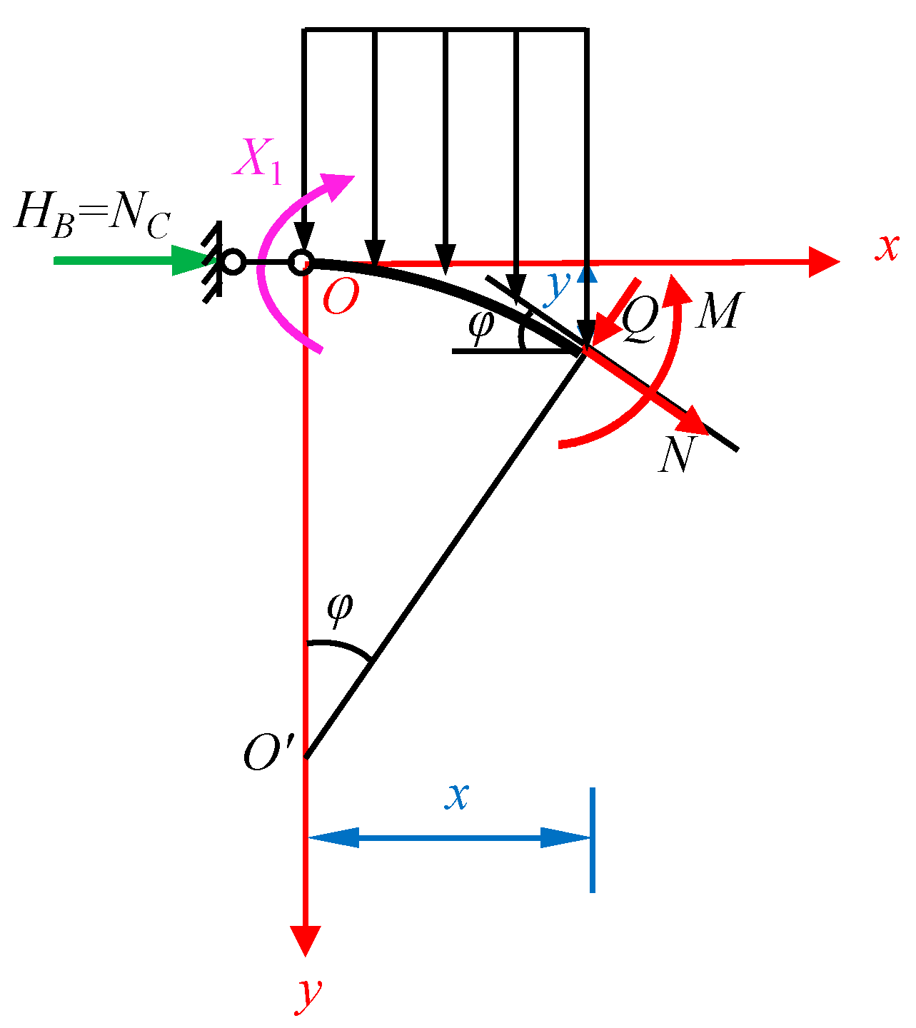
2.2.4. Calculation of Internal Forces in the Arch Ring Section

The internal forces at the arch vault section C are:
  • bending moment:
M C = X 1 = P t R 2 a 3 b 1 a 2 b 3 + R 3 a 3 b 2 a 2 b 4 a 1 a 3 - a 2 2
axial force:
N C = X 2 = P t R a 2 b 1 a 1 b 3 + R 2 a 2 b 2 a 1 b 4 a 2 2 a 1 a 3
For arch foot support B, the free-body diagram of the right half-arch ring is presented in Figure 4a. Based on the equilibrium equation of force, the support reaction forces at arch foot B are obtained as follows:
  • bending moment:
M B = M 1 ¯ X 1 + M 2 ¯ X 2 + M P 1 x B = X 1 + X 2 f P t 2 R 2 sin 2 φ B γ 2 R 3 sin φ B sin φ B φ B 2 + 1 4 sin 2 φ B       + γ 2 R 3 1 2 sin 2 φ B + 1 3 cos 3 φ B 1 3
horizontal thrust:
H B = N C = X 2
vertical reaction force:
V B = 0 l 2 P d x = P t l 2 + 0 l 2 γ 2 y d x = P t l 2 + γ 2 0 φ B R R cos φ d R sin φ = P t l 2 + γ 2 R 2 sin φ B φ B 2 1 4 sin 2 φ B
The force diagram of the isolated body in any section of the right half-arch ring is given in Figure 4b. Depending on the force balance, the internal force functions in any section of the right arch ring shall be expressed as:
M φ = M 1 ¯ X 1 + M 2 ¯ X 2 + M P 1 x = X 1 + X 2 R 1 cos φ P t 2 R 2 sin 2 φ       γ 2 R 3 sin 2 φ 2 φ 2 sin φ sin φ sin 2 φ 4 cos 3 φ 3 + 1 3
Q φ = N C sin φ 0 x P d x cos φ = X 2 sin φ P t R sin φ cos φ γ 2 R 2 cos φ sin φ φ 2 - 1 4 sin 2 φ
N φ = N C cos φ + 0 x P d x sin φ = X 2 cos φ + P t R sin 2 φ + γ 2 R 2 sin φ sin φ φ 2 1 4 sin 2 φ
The bending moments and axial forces of the left half-arch ring in any section are the same as those of the right half-arch ring symmetrically, while the shear forces are antisymmetrically the same in the opposite direction.

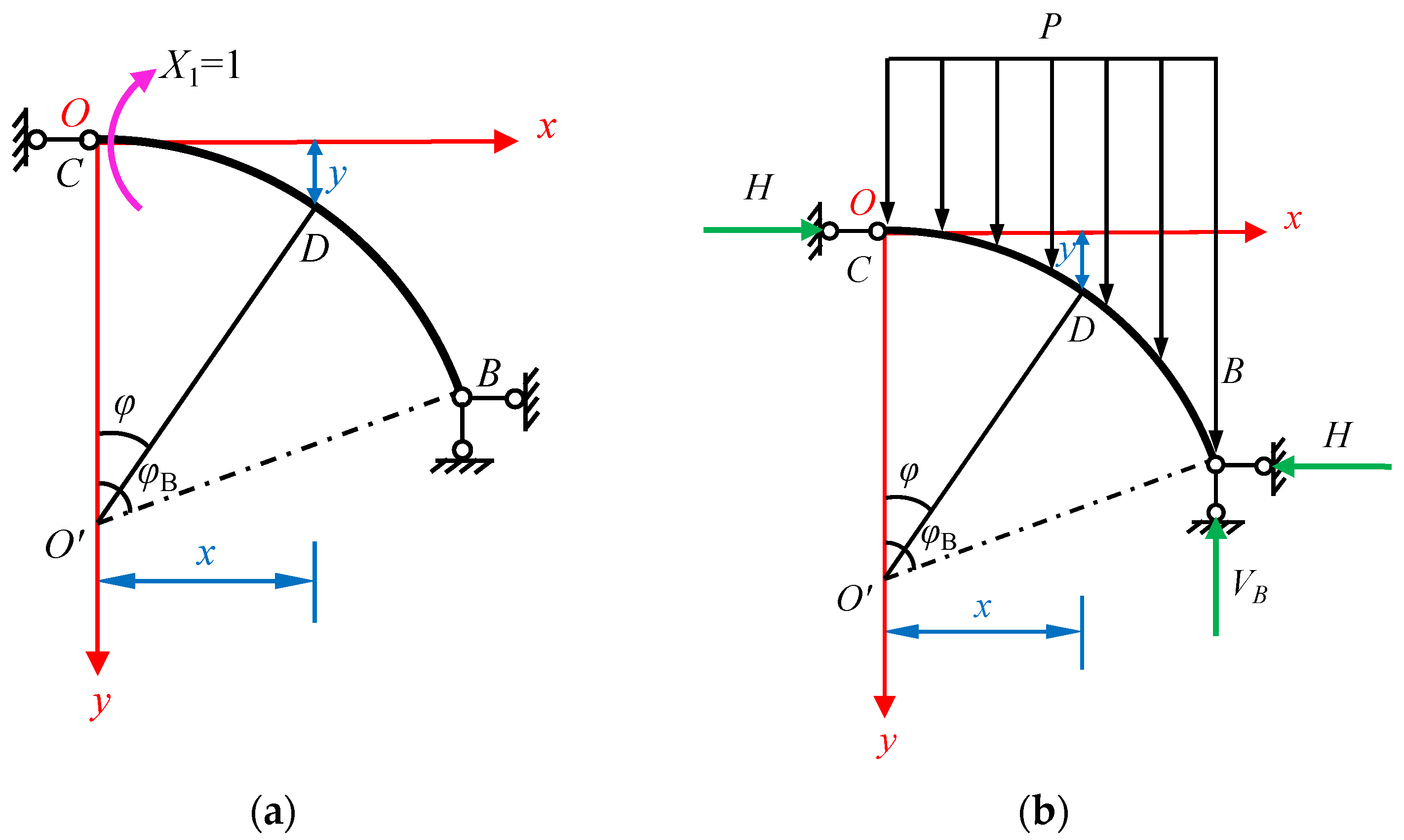
2.3. Derivation of force Calculation Formula for Circular Arch Ring under the Calculation Model of Two-Hinged Arch

If the bending moment at the arch foot is not considered, the foot of the arch can be modeled as a fixed hinged support and the mechanical model of the arch ring of the freestanding stone cave-dwelling is a two-hinged arch, as shown in Figure 5a. The coordinate axes are set in the same way as for the hingeless arch, the arch axis equation is identical to Formulas (1) and (5).

2.3.1. Selection of Basic System and Equation of Force Method

Because the structure and the acting load are symmetrical, the shear force at the vault of the arch QC = 0. Two-hinged arch can be optimized as a half-span structure for calculation, which is a primary statically indeterminate structure. The basic system chosen is shown in Figure 5b.
The basic system shall meet the deformation condition that the rotation angle at the vault C (i.e., the coordinate origin O) is equal to zero. Therefore, the equation of force method is:
δ 11 X 1 + Δ 1 P = 0

2.3.2. Calculation of Force Method Coefficient and Free Term

As shown in Figure 6a, the internal force calculation result of the basic structure under the action of X1 = 1 is as follows:
M 1 ¯ = 1 - y f
As shown in Figure 6b, under the actual load P, the horizontal reaction H of the simply supported curved beam is:
H = 1 f 0 l 2 l 2 x P t + γ 2 y d x = 1 f 1 8 P t l 2 + l 2 γ 2 R 2 sin φ B φ B 2 sin 2 φ B 4 γ 2 R 3 sin 2 φ B 2 + cos 3 φ B 3 1 3
The bending moment equation for the basic structure under load P for a section at a distance x from point O is:
M P 0 x = H y P t 2 x 2 x 0 x γ 2 y d x - 0 x x γ 2 y d x = H R R cos φ P t 2 R 2 sin 2 φ γ 2 R 3 sin 2 φ 2 φ sin φ 2 sin φ sin 2 φ 4 cos 3 φ 3 + 1 3
The main coefficient for the force method is calculated as follows:
E I δ 11 = M 1 ¯ 2 d s = 1 y f 2 d s = 0 φ B 1 R R cos φ f 2 R d φ = R φ B 2 R 2 f φ B - sin φ B + R 3 f 2 φ B - 2 sin φ B + φ B 2 + sin 2 φ B 4
The free term of the force method is calculated as follows:
E I Δ 1 P = M 1 ¯ M P 0 x d s = 0 φ B 1 y f H R R cos φ P t 2 R 2 sin 2 φ γ 2 R 3 sin 2 φ 2 φ sin φ 2 sin φ sin 2 φ 4 cos 3 φ 3 + 1 3 R d φ = H R 2 φ B sin φ B 3 2 R φ B 2 R sin φ B + 1 4 R sin 2 φ B f P t R 3 φ B 4 1 8 sin 2 φ B       γ 2 R 4 7 φ B 12 1 8 sin 2 φ B + 1 2 φ B cos φ B 5 sin φ B 6 sin 3 φ B 18 + P t R 4 f φ B 4 1 8 sin 2 φ B 1 6 sin 3 φ B       + γ 2 R 5 f 37 48 φ B + 1 48 sin 2 φ B + 1 2 φ B cos φ B 7 6 sin φ B 4 9 sin 3 φ B 1 8 φ B cos 2 φ B 1 192 sin 4 φ B

2.3.3. Calculation of Redundant Unknown Force

Substitute Formulas (26), (28), and (29) into Formula (24), the redundant unknown force X1 can be obtained:
X 1 = Δ 1 P δ 11

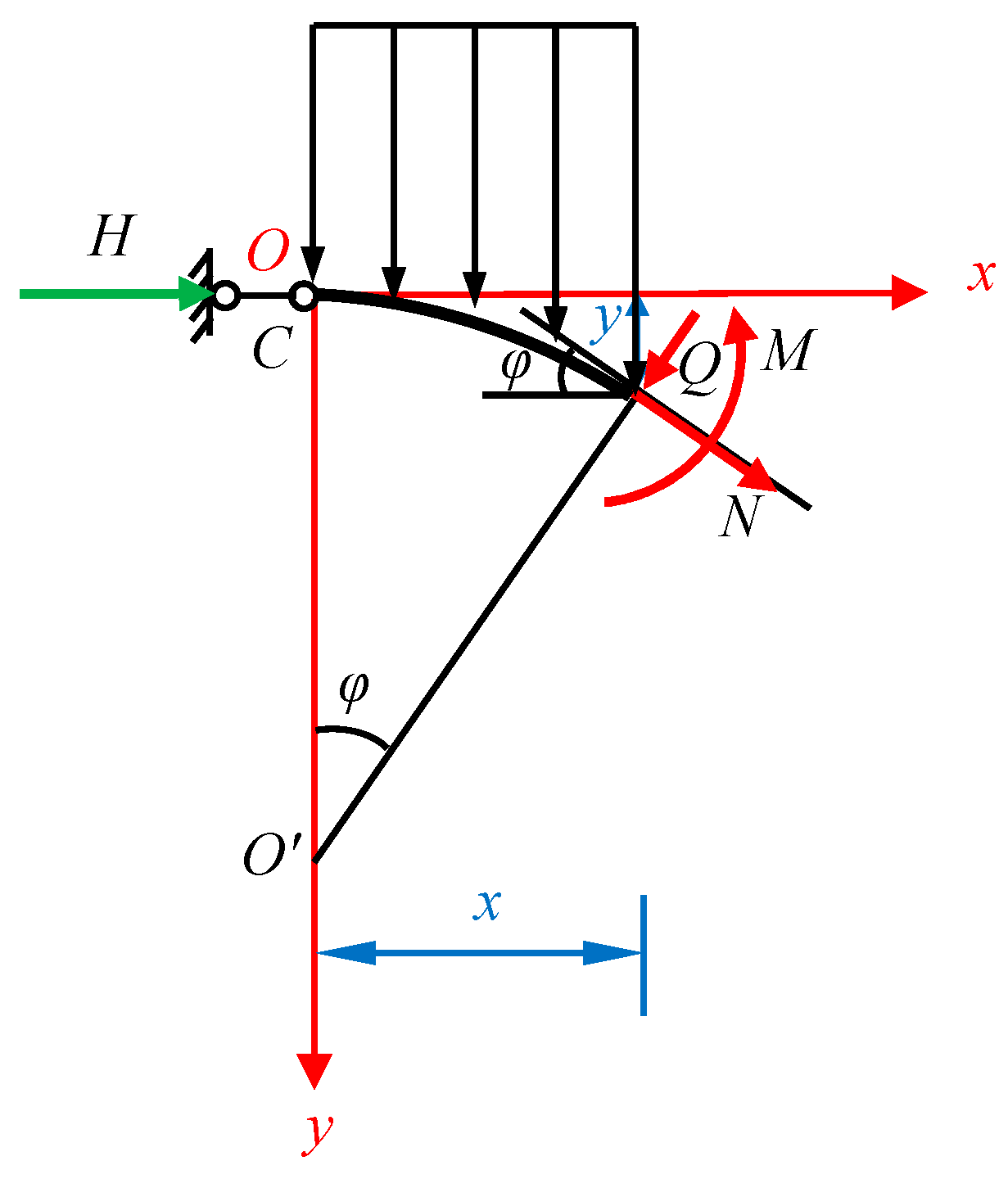
2.3.4. Calculation of Internal Forces in the Arch Ring Section

According to the force diagram shown in Figure 5b, the internal forces at the arch vault section C are:
  • bending moment:
M C = X 1
axial force
N C = 1 f P t 2 x B 2 + x 0 l 2 γ 2 y d x 0 l 2 x γ 2 y d x X 1 = 1 f P t 2 R 2 sin 2 φ B + γ 2 R 3 1 2 sin 2 φ B φ B 2 sin φ B 1 4 sin φ B sin 2 φ B 1 3 cos 3 φ B + 1 3 X 1
The support reaction forces at arch foot B are obtained as follows:
  • bending moment:
M B = 0
horizontal thrust
H B = N C
the vertical reaction force VB is identical to the Formula (20).
The force diagram in any section of the right half-arch ring at a distance x from point O is shown in Figure 7, according to the conditions of force balance, the internal force functions in any section of the right half-arch ring are:
M φ = M 1 ¯ X 1 + M P 0 x = 1 y f X 1 + H R R cos φ P t 2 R 2 sin 2 φ       γ 2 R 3 sin 2 φ 2 φ 2 sin φ sin φ sin 2 φ 4 1 3 cos 3 φ + 1 3
Q φ = N C sin φ 0 x P d x cos φ = H B sin φ P t R sin φ cos φ γ 2 0 φ R R cos φ d R sin φ cos φ = H B sin φ P t R sin φ cos φ γ 2 R 2 cos φ sin φ φ 2 1 4 sin 2 φ
N φ = N C cos φ + 0 x P d x sin φ = H B cos φ + P t R sin 2 φ + γ 2 0 φ R R cos φ d R sin φ sin φ = H B cos φ + P t R sin 2 φ + γ 2 R 2 sin φ sin φ φ 2 1 4 sin 2 φ
Because of the symmetry of loads on the two-hinged arch structures, the bending moments and axial forces on the left and right half-arch ring sections are symmetrical and the shear forces are anti-symmetrical.

2.4. Derivation of Force Calculation Formula for Circular Arch Ring under the Calculation Model of Three-Hinged Arch

The three-hinged arch calculation model does not take into account the bending moment borne by the stone cave-dwelling arch ring at the foot of the arch, the arch footing bearing is directly considered as a fixed hinge support, and the arch vault is simplified as hinge joint without considering the restrained bending moment, that is, the bending moment at the arch vault is equal to zero. and its mechanical calculation model is shown in Figure 8a. The setting of the coordinate axis is also to set the origin O in the arch vault, with the X axis to the right and the Y axis to the down. The arch axis equation is the same as Equation (2).

2.4.1. Simplicity of Calculation Model and Determination of the Support Reaction Force

Due to the symmetrical loads, the three-hinged arch can be simplified to a half-arch structure as shown in Figure 8b.
The horizontal reaction force H of the half-arch structure is the same as Formula (26). The vertical reaction force V at the arch foot is equal to the Formula (20).

2.4.2. Internal Force Formula of Any Section of Arch Ring

The isolator force diagram in any section of the right half-arch ring is shown in Figure 9. By the equilibrium of forces, the internal force functions in any section of the right half-arch ring are respectively:
M φ = H y P t 2 x 2 x 0 x γ 2 y d x 0 x x γ 2 y d x = H R R cos φ P t 2 R 2 sin 2 φ       γ 2 R 3 1 2 sin 2 φ φ 2 sin φ 1 4 sin φ sin 2 φ 1 3 cos 3 φ + 1 3
Q φ = H sin φ - 0 x P d x cos φ = H sin φ P t R sin φ cos φ γ 2 R 2 cos φ sin φ φ 2 1 4 sin 2 φ
N φ = H cos φ + 0 x P d x sin φ = H cos φ + P t R sin 2 φ + γ 2 R 2 sin φ sin φ φ 2 1 4 sin 2 φ

3. Results and Analysis

3.1. Example Parameter

According to the dimension records of freestanding cave dwellings in northern Shaanxi, China, the selected parameters are listed in Table 1. Then it is determined that the load concentration on any section of the arch ring is P = Pt + 26y = 37.06 + 26y, the circular arc radius R = 1.83 m, and the half-arch ring central angle φB = 1.3895 rad.

3.2. Simulation Verification

To verify the accuracy and reliability of the formulae for calculating the internal forces of the arch ring under the three mechanical models derived from the aforementioned theory, The Structural Mechanics Solver (abbreviated as SM Solver), which was developed based on the principle of matrix displacement method, was used to calculate the internal forces of these three mechanical models. The arc arch was divided into 20 segments, and the hingeless, two-hinged, and three-hinged arch models were simulated by first establishing the nodes, then the units and supports, and finally applying the loads. The curved load on the top of the arch ring is simulated by applying the unit load to each unit in a linearly distributed way, see Figure 10. If the material properties are entered, the internal force calculation can be executed.

3.3. Comparison and Analysis of Calculation Results under the Three Mechanical Models

3.3.1. Comparison of Support’s Reaction Force

The bearing reactions of the arch foot under an unhinged arch calculated by Formulas (17), (19), and (20), the bearing reactions of the arch foot under a two-hinged arch calculated by Formulas (20), (32), and (33), the bearing reactions of the arch foot under a three-hinged arch calculated by Formulas (20) and (26), and the bearing reactions calculated by the SM Solver are listed in Table 2.
As can be seen from Table 2, the results of theoretical calculations and numerical simulations are close to each other, indicating the high reliability of the theoretically derived bearing reaction force calculation formulae under the three mechanical models of the arch ring. The comparison of the theoretical calculation results shows that the vertical support’s reaction force V is the same for the hingeless arch, two-hinged arch, and three-hinged arch with the same arch axis. However, the horizontal thrust of the hingeless arch is the largest, followed by the thrust of the three-hinged arch, and the thrust of the two-hinged arch is the smallest. The difference between the horizontal thrust of the hingeless arch and the three-hinged arch is (48.54 − 44.76)/44.76 = 8.4% < 10%, and the difference between the horizontal thrust of the two-hinged arch and the three-hinged arch is (44.76 − 40.96)/44.76 = 8.5% < 10%. Therefore, although there is a difference in the magnitude of the horizontal thrusts under the three calculation models, the difference is not significant.

3.3.2. Comparison of Cross-Section Internal Forces in the Arch Ring

The internal forces at the vault and foot sections of the right half-arch ring for the hingeless, two-hinged, and three-hinged arches are calculated from Formulas (16)–(18), (22), (23), (31), (32), (35), (36), (38) and (39); the absolute maximum values of the internal forces of the sections of the whole right half-arch ring are determined from Formulas (21)–(23) and (34)–(39); and the corresponding results calculated by SM Solver are listed in Table 3. As can be seen, the results obtained from the theoretical calculation and numerical simulation are basically the same, and the difference in shear force is too large because the SM Solver adopts some segmental lines to simulate the circular arc arch, and the curved load on the arch ring uses linear distributed load to be applied in segments, which does not exactly match with the actual force, resulting in a deviation from the theoretical calculation results, and the calculation accuracy will be improved if more units are divided. According to the analysis, the internal force calculation formula obtained from the theoretical derivation is more accurate compared with the numerical simulation. Therefore, only the theoretical calculation results are discussed later.
For these three mechanical models, the shear force at the arch vault section is zero; the maximum absolute shear force occurs at the arch foot support, and the relative deviation of the three values is within 13%, with the maximum shear force value for the hingeless arch, the second largest for the three-hinged arch and the smallest for the two-hinged arch. The maximum axial force occurs near the foot of the arch and the maximum difference between the three is only 1.7%, which is relatively close to each other; the axial force in the vault section of the arch is approximately half of the axial force in the foot of the arch. However, the bending moments at the arch vault and foot sections differ significantly for the three mechanical models. At the vault of the arch, the bending moment of the three-hinged arch is zero, followed by the unhinged arch, and the two-hinged arch is the largest; at the foot of the arch, the hingeless arch has a bending moment, while the bending moments of the two-hinged arch and three-hinged arch are zero. The relative deviation of the maximum absolute values of the section bending moment obtained from the three mechanical models is around 15%, with the three-hinged arch having the largest value, the hingeless arch the second largest, and the two-hinged arch the smallest.
Under symmetrical load, M(φ) and N(φ) diagrams of the right half-arch ring are symmetrical with those of the left half-arch ring, while Q(φ) diagram is anti-symmetric. According to Formulas (21)–(23) and (34)–(39), only the range of φ ∈ [0,1.3895] rad is drawn, that is, M(φ), Q(φ) and N(φ) diagrams of the right half arch under the three calculation models, which are shown in Figure 11. It can be concluded that the cross-sectional bending moment of the arch shaft determined by the hingeless arch and two-hinged arch models can be divided into two categories: interior tensioned and exterior tensioned, and there is a reverse bending point on the arch shaft, while the cross-sectional bending moment obtained by the three-hinged arch model is only exterior tensioned. The distribution law of the three bending moment diagrams is roughly the same, and they can be divided into two parts. The first part is that the bending moments decrease gradually from the arch vault to a third of the section away from the arch foot, and the bending moment of the three-hinged arch decreases from zero to the maximum negative bending moment of external tension, while the hingeless arch and two-hinged arch decrease from the positive bending moment of internal tension to zero and then to the maximum negative bending moment of external tension. In the second part, the bending moments gradually increase from the section one-third away from the arch foot to the arch foot, and the maximum negative bending moments of the three-hinged arch and two-hinged arch reaches zero at the arch foot; the negative bending moment of hingeless arch gradually increases to zero from external tension and reaches the maximum positive bending moment of internal tension at the arch foot. The distribution law of the shear force diagrams is that the shear force starts from zero at the arch vault and gradually decreases to a maximum negative shear force near one-half of the half-arch span; from there the shear force gradually increases, turning from negative to positive values until it reaches a maximum positive shear force at the arch foot. The distribution law of the axial force diagrams is from the arch vault to the arch foot, and the axial force of the arch vault decreases gradually. The value of the axial force of the arch vault is roughly half of that of the arch foot, and the whole span is under pressure.
In conclusion, no matter which of the three mechanical models is adopted in the calculation of the internal forces of the arch ring of the stone cave-dwelling, the change trends of the shear force diagram and the axial force diagram are basically the same, but the bending moment diagram is slightly different. Hingeless arch and two-hinged arch models have bending moments of internal tension at the arch vault, and there are two kinds of bending moments in the cross-section of the half-arch ring, positive internal tension and negative external tension, which are evenly distributed. The maximum tensile stress of a two-hinged arch occurs in the arch vault, and the maximum tensile stress of a hingeless arch occurs in the arch foot, which is consistent with the characteristic that the actual cracking damage of cave dwellings usually occurs in the vault and foot of the arch. However, under the three-hinged arch model, the bending moment at the vault of the arch is zero, and the whole cross-section bending moment of the half-arch ring is externally tensile, which is also larger than that of the hingeless arch and the two-hinged arch. The maximum tensile stress is near the section with the maximum absolute bending moment, that is, about one-third of the half-arch span from the arch foot. Therefore, compared with the three-hinged arch, the hingeless arch and two-hinged arch take the bending moment of the arch vault into account, which is closer to the actual engineering situation; As the maximum tensile stress calculated by the two-hinged arch is larger than that of the hingeless arch, it will be safer, more accurate and more reliable to use the two-hinged arch in the mechanical analysis of the arch ring in the cave dwellings. Because the calculation result of the three-hinged arch is slightly larger, it can be used for rough calculation in engineering design.

3.4. Section Design and Recheck of the Arch Ring

For the arch ring of freestanding stone cave-dwelling, the maximum value of normal tensile stress of flexural member under the combined action of bending moment and axial force shall meet the design value of tensile strength of the arch ring material, that is:
σ max = M I h 1 2 - N A σ
And the maximum value of shear stress of the flexural member shall also meet the design value of shear strength of arch ring material, that is:
τ max = 3 2 Q max A τ
As the load distribution of stone freestanding cave-dwelling is uniform along the depth direction, the unit length b = 1 m is taken as the calculation unit. Then the arch ring thickness h1 can be obtained from Formulas (40) and (41), which shall meet the requirements of the following formula:
h 1 - N + N 2 + 24 σ M · 10 3 2 σ
and
h 1 1.5 Q max τ
In Formulas (40)–(43), M and N are the bending moment and axial force at the most dangerous cross-section of the arch ring, and the units are kN·m and kN respectively; Qmax represents the maximum shear force in the arch ring cross-section, and the unit is kN; I represents the moment of inertia of the arch ring section, and its unit is mm4, which is calculated as bh13/12, b = 1000 mm; A represents the cross-sectional area of the arch ring, calculated as bh1; [σ], [τ] respectively represent the design value of bending tensile strength and bending shear strength of arch ring materials, and the units are MPa.

4. Conclusions

The arch ring of freestanding stone cave-dwelling is simplified into three mechanical calculation models, namely, hingeless arch, two-hinged arch, and three-hinged arch. Following the principle of force method in structural mechanics, the formulae of internal force of the arch ring in freestanding stone cave-dwelling based on the aforementioned three calculation models are deduced respectively, which are verified by numerical simulation with good results. Therefore, the distribution of the cross-section internal force and the difference in force calculation results of the arch ring in the freestanding cave-dwelling under the three mechanical calculation models are revealed. The following conclusions are drawn:
  • Under the aforementioned three mechanical calculation models, the vertical reactions of the support are equivalent, the horizontal thrust is basically the same, and the relative difference is less than 10%.
  • Under the aforementioned three mechanical calculation models, the maximum shear force occurs at the support of the arch foot; The maximum axial force occurs near the support of the arch foot, and the axial force of the arch vault section is roughly half of that of the arch foot. The distribution trend of the shear force diagram and axial force diagram is basically the same, and the values of axial force and shear force are similar, but the bending moment diagram is different. The bending moment diagrams of the hingeless arch and the two-hinged arch are more evenly distributed than those of the three-hinged arch. In addition, under these two mechanical calculation models, there is a certain bending moment at the top of the arch ring, which is close to the actual situation.
  • The theoretical calculation results under the hingeless arch and two-hinged arch models are more consistent with the actual failure characteristics. The two-hinged arch calculation model is safer, more accurate, and more reliable than the hingeless arch calculation model when it is used in the force analysis of the circular arc arch ring. But the three-hinged arch can be used for a rough estimation.
The above conclusions can provide mechanical support for the further safe design, construction, inheritance, and sustainable development of freestanding stone cave dwellings.

Author Contributions

Conceptualization, Y.H.; Methodology, Y.H. and Y.L.; Software, Y.H. and Y.L.; Validation, Y.H. and Y.L.; Formal analysis, Y.H.; Investigation, Y.L.; Data curation, Y.H.; Writing—original draft preparation, Y.H.; Writing—review and editing, Y.H.; Visualization, Y.H. and Y.L.; Supervision, Y.L.; Project administration, Y.H. and Y.L.; Funding acquisition, Y.H. All authors have read and agreed to the published version of the manuscript.

Funding

This research was funded by the Natural Science Basic Research Project, the Science & Technology Department of Shaanxi Province, grant number 2022JM-266, National College Students’ Innovation and Entrepreneurship Training Program, grant number 202110719057, and the Undergraduate Innovation Project of Yan’an University, grant number D2020134.

Institutional Review Board Statement

Not applicable.

Informed Consent Statement

Not applicable.

Data Availability Statement

The data presented in this study are available on request from the corresponding author.

Conflicts of Interest

The authors declare no conflict of interest.

References

  1. Wang, Z.; Wei, Q.; He, Y. Study on Constructive System of Green Cave Dwelling in Loess Plateau—Interpretation with the “Regional Gene” Theory. J. Zhejiang Univ.-Sci. A 2007, 8, 1754–1761. [Google Scholar] [CrossRef]
  2. Hu, X.F.; Zhang, F.L.; Xue, J.Y.; Zhu, W.W.; Liu, S.; Dai, M.X. Disease Analysis and Reinforcement Measures of Loess Caves. Ind. Constr. 2019, 49, 6–13. [Google Scholar]
  3. Zhang, F.L.; Tian, P.G.; Zhu, W.W.; Yang, K.; Hu, X.F.; Fan, D.G. Analysis of Mechanical Properties of Cave Dwelling Structure and Research on Reinforcement and Protection Technology; China Construction Industry Press: Beijing, China, 2020. [Google Scholar]
  4. Akubue, J. Earth Sheltered Housing; Design Concepts for Urban Ground-Scrapers. Int. J. Archit. Arts Appl. 2021, 7, 7. [Google Scholar] [CrossRef]
  5. Korsavi, S.; Mehdizade, S. The Earth and Ice-Pits Sustainable Architecture in Iran. In Proceedings of the European Conference on Sustainability, Energy and the Environment, Brighton, UK, 4–7 July 2013. [Google Scholar]
  6. Zeng, X.D.; Song, D.M. Green Design Explore of Earth-Sheltered Architecture: A Case Study of Chongqing Empirical Study Center of Architecture Energy-Saving Technology. J. Civ. Archit. Environ. Eng. 2011, 33, 104–108. [Google Scholar]
  7. Lee, J.H.; Choi, W.K.; Suh, S.J.; Cho, D.W. A Study on the Energy Needs Patterns for the House According to the Earth Sheltering Method. J. Archit. Inst. Korea Plan. Des. 2008, 24, 233–240. [Google Scholar]
  8. Tundrea, H.; Maxineasa, S.G.; Simion, I.M.; Taranu, N.; Budescu, M.; Gavrilescu, M. Environmental Impact Assessment and Thermal Performances of Modern Earth Sheltered Houses. Environ. Eng. Manag. J. 2014, 13, 2363–2369. [Google Scholar]
  9. Atkison, L.J. Earth Sheltered Housing/Cold Climate Design. In The Potential of Earth-Sheltered and Underground Space, 1st ed.; Holthusen, T.L., Ed.; Pergamon Press: Oxford, UK, 1981; pp. 187–190. [Google Scholar]
  10. Krundyshev, B.L. Engineering Composition Factors Optimization & Classification in the Earth Sheltered Housing Design. Int. J. Appl. Eng. Res. 2017, 12, 10848–10855. [Google Scholar]
  11. Hayashi, Y. The Future of Earth-Sheltered Architecture in China’s Farming Villages. Tunn. Undergr. Space Technol. 1986, 1, 167–169. [Google Scholar] [CrossRef]
  12. Staff, G.B. Earth-Sheltered Houses: How to Build an Affordable Underground Home; New Society Publishers: Gabriola, BC, Canada, 2006. [Google Scholar]
  13. Tong, L.P.; Han, C.P. Earth-Arched Structural Systems of Primitive Earth-Sheltered Dwelling. Constr. Technol. 2008, 37, 113–115. [Google Scholar]
  14. Tong, L.P.; Han, C.P. Study on the Structural Properties of Self-Support Systems for Earth-Sheltered Dwelling. Sichuan Build. Sci. 2009, 35, 71–73. [Google Scholar]
  15. Chen, R.F. Scientific Research on the Traditional Construction of Dikeng Cave Dwellings. Master’s Thesis, Zhengzhou University, Zhengzhou, China, 2011. [Google Scholar]
  16. Cao, Y.; Zhang, Y.X.; Tong, L.P. Study on Size Design and Its Influence on Mechanical Properties of Sunken Cave Dwelling. Build. Sci. 2012, 28, 103–107. [Google Scholar]
  17. Hao, Y.e.; Liang, X.W.; Yang, H.X. Static Behavior and Strengthening Methods of Single-Hole Loess Cave Dwelling by Cliff in Yan’an of Northern Shaanxi. Henan Sci. 2016, 34, 1852–1857. [Google Scholar]
  18. Liu, B.T.; Liu, X.L.; Zhang, S. Analysis of Pressure Arch Effect and Failure Mode of Cliff-Type Cave Dwellings with Different Covering Soil Thickness. China Non-Met. Miner. Ind. 2018, 132, 36–40+44. [Google Scholar]
  19. Guo, P.G. Stability Analysis of Loess Cave Dwellings under Longitudinal Earthquake. Earthq. Resist. Eng. Retrofit. 2016, 38, 133–138. [Google Scholar]
  20. Guo, P.G.; Tong, L.P. Influence of Crosswise Earthquake on Loess Cave Dwellings’ Stability. Earthq. Eng. Eng. Dyn. 2015, 35, 56–63. [Google Scholar]
  21. Hao, Y.e.; Liang, X.W.; Lan, Y.Q. Numerical Simulation and Dynamic Analysis of Single-Hole Cliff-Side Loess Cave Dwelling under Seismic Actions. Geofluids 2021, 2021, 6890445. [Google Scholar] [CrossRef]
  22. Xue, J.Y.; Zhao, X.B.; Zhang, F.L.; Hu, X.F.; Liu, X.H. Shaking Tabletest on Model Structure of Underground Loess Cave. J. Build. Struct. 2021, 42, 14–23. [Google Scholar]
  23. Tong, L.P.; Xu, C.X. Testing and Evaluation of Indoor and Outdoor Thermal Environment of Sunken Cave Dwelling in Summer. Build. Sci. 2015, 31, 9–14. [Google Scholar]
  24. Zhu, J.Y.; Nie, P.; Tong, L.P.; Zhao, X.; Xing, C.J. Thermal Responsive Characteristics of Cliff-Side Cave Dwellings in West Area of He’ Nan under Extreme Climate Conditions. Build. Sci. 2017, 33, 76–81+89. [Google Scholar]
  25. Zhu, J.Y.; Tong, L.P. Study on Thermal Performance of Underground Cave Dwelling in West Area of He’ Nan in Winter. Build. Sci. 2016, 32, 99–105+126. [Google Scholar]
  26. Han, J.M.; Su, S.Q. Stability Analysis of Weibei Pitted Loess Cave Dwellings in Rainfall Infiltration. J. Archit. Civ. Eng. 2012, 29, 104–110. [Google Scholar]
  27. Wang, N.Q.; Zhang, S. Sensitivity Analysis of Stability of Cave Dwellings Based on Orthogonal Design. Sci. Technol. Eng. 2017, 17, 119–124. [Google Scholar]
  28. Wang, N.Q.; Zhang, S. Quantitative Evaluation of Stability on Loess Cave Dwellings Based on Blind Data Theory. Chin. J. Undergr. Space Eng. 2017, 13, 822–827. [Google Scholar]
  29. Wu, C.J.; Gan, Z.M.; Meng, C.P. Stability of Cave Dwelling of Loess Hills in North Part of Shaanxi Province. J. Shaanxi Norm. Univ. (Nat. Sci. Ed.) 2005, 33, 119–122. [Google Scholar]
  30. Wu, W.; Ji, D. Using Flac3D to Simulation and Analysis of Cave Dwelling Stability. Int. J. Digit. Content Technol. Its Appl. 2012. [Google Scholar] [CrossRef]
  31. Wu, W.L.; Yang, H.X. Stability Analysis of the Loess Cave Dwelling in Shanbei Region Using Comsol. Ind. Constr. 2017, 47, 119–122. [Google Scholar]
  32. Yang, K.; Zhang, F.L.; Zhu, W.W.; Xue, J.Y.; Zhou, H.L.; Dai, M.X.; Liu, J. Stability Analysis of Loess Cave Dwelling by Cliff Based on Strength Reduction Method. Ind. Constr. 2019, 49, 25–30. [Google Scholar]
  33. Tong, L.P.; Zhang, M. Application of Brick -Arch Technology on Reinforcement of Earth Sheltered Dwelling. Constr. Technol. 2016, 45, 82–85. [Google Scholar]
  34. Xue, J.Y.; Ling, H.Q.; Zhou, H.L.; Zhang, F.L.; Zhao, X.B. Shaking Table Tests for Independent Stone Hoop Cave Reinforcement Model. J. Vib. Shock 2022, 41, 211–221. [Google Scholar]
  35. Zhang, F.L.; Tian, P.G.; Bian, Z.W.; Lei, B.; Yun, Z.Y.; Shi, J.C. The Strengthening Method of Loess Cave Based on the Stress Mechanism of Arch Structure and New Brick Arch. In Proceedings of the 12th Academic Conference on Building Construction Renovation and Disease Treatment, Zhengzhou, China, 25–26 November 2018. [Google Scholar]
  36. Zhang, F.L.; Zhou, G.M.; Xue, J.Y.; Zhao, X.B.; Hu, X.F.; Liu, Z.Q. Shaking Table Test on Damaged Brick Hoop Caves Strengthened by Cement Mortar Coating with Polypropylene Packing Belt Meshes. J. Build. Struct. 2021, 42, 113–124. [Google Scholar]
  37. Wang, F.J.; Liu, R.S.; Ma, Z.H. Damage Measures Analysis of Independent Cave Dwelling under Earthquake. Sci. Technol. Eng. 2018, 18, 281–286. [Google Scholar]
  38. Yan, Y.M. Force Analysis and Section Calculation of Arch Ring of Stone-Built Cave. Proc. Fifth Natl. Conf. Struct. Eng. 1996, 1, 672–675. [Google Scholar]
  39. Yan, Y.M.; Guo, B.S. Research on the Reasonable Arch Ring of Stone-Built Cave. Proc. Fourth Natl. Conf. Struct. Eng. 1995, 3, 655–658. [Google Scholar]
  40. Zhang, Y.X.; Tian, X.Y. Destroy Causes of Cave Dwelling and Its Cure Measure. J. Northwest Univ. Agric. For. Sci. Technol. (Nat. Sci. Ed.) 2004, 32, 145–149. [Google Scholar]
  41. Huang, C.H.; Wang, Z.J. Structure Analysis on the Cave Dwelling. J. Chang. Inst. Technol. (Nat. Sci. Ed.) 2009, 10, 46–48. [Google Scholar]
  42. Bao, S.H. Structural Mechanics, 3rd ed.; Wuhan University of Technology Press: Wuhan, China, 2008. [Google Scholar]
  43. Chen, Z.H.; Wen, G.Z.; Wang, D.Q.; Liu, H.J.; Chen, M.D. Structural Mechanics, 1st ed.; Higher Education Press: Beijing, China, 2020. [Google Scholar]
Figure 1. Freestanding stone cave-dwelling. (a) Ground floor plan; (b) Axonometric drawing; (c) Realistic scene.
Sustainability 15 09545 g001
Figure 2. Composition of a freestanding stone cave-dwelling.
Sustainability 15 09545 g002
Figure 3. Calculation model of a hingeless arch. (a) Calculation diagram of a hingeless arch; (b) Basic system of a hingeless arch.
Sustainability 15 09545 g003
Figure 4. Force diagram of the right half-arch ring: (a) For the arch foot support B; (b) For any section of the right half-arch ring.
Sustainability 15 09545 g004
Figure 5. Calculation model of a two-hinged arch. (a) Calculation diagram of a two-hinged arch; (b) Basic system of a two-hinged arch.
Sustainability 15 09545 g005
Figure 6. Force diagram of the basic structure under load. (a) Under unit load X1 = 1; (b) Under actual load P.
Sustainability 15 09545 g006
Figure 7. Force diagram of isolator in any section of the two-hinged arch.
Sustainability 15 09545 g007
Figure 8. Calculation model of a three-hinged arch. (a) Calculation diagram of a three-hinged arch; (b) The half-arch structure of a three-hinged arch.
Sustainability 15 09545 g008
Figure 9. Force diagram of the isolator of any section of the three-hinged arch.
Sustainability 15 09545 g009
Figure 10. Numerical simulation models: (a) Hingeless arch; (b) Two-hinged arch; (c) Three-hinged arch.
Sustainability 15 09545 g010
Figure 11. Internal force diagrams of the right half-arch under three calculation models. (a) M; (b) Q; (c) N.
Sustainability 15 09545 g011
Table 1. The selected parameter values.
Parameters NameValue
span-length l (m)3.6
arch height f (m)1.5
arch ring thickness h1 (mm)250
covering soil thickness h2 (m)1.0
arch ring self-weight γ1 (kN/m3)24.8
filling soil self-weight γ2 (kN/m3)
uniformly distributed live load on the roof q (kN/m2)
item coefficient of normal permanent load γG
20
2.0
1.3
item coefficient of active load γQ1.5
combined value coefficient ψ0.7
Table 2. The bearing reactions at the support of the arch foot under three calculation models.
Bearing ReactionsHingeless ArchTwo-Hinged ArchThree-Hinged Arch
horizontal thrust (kN)48.54 (46.62)40.96 (41.02)44.76 (44.83)
vertical reaction (kN)84.14 (84.47)84.14 (84.47)84.14 (84.47)
Note: The values in parentheses are the results calculated by the SM Solver.
Table 3. Internal forces at special sections of the arch ring under three calculation models.
Calculation Model TypeSection PositionBending Moment M (kN·m)Shearing Force Q (kN)Axial Force N (kN)
Hingeless archArch vault3.29 (3.95)0 (2.30)48.54 (46.56)
Arch foot8.97 (6.64)32.57 (16.49)91.51 (95.06)
Maximum absolute values8.97 (6.64)32.57 (20.56)91.67 (95.06)
Two-hinged archArch vault5.70 (5.71)0 (2.02)40.96 (40.97)
Arch foot0 (0)25.12 (11.20)90.15 (93.23)
Maximum absolute values7.47 (7.33)25.12 (15.27)90.15 (93.23)
Three-hinged archArch vault0 (0)0 (2.21)44.76 (44.77)
Arch foot0 (0)28.85 (14.80)90.83 (94.48)
Maximum absolute values9.96 (9.80)28.85 (18.87)90.87 (94.48)
Note: The values in parentheses are the results calculated by the SM Solver.
Disclaimer/Publisher’s Note: The statements, opinions and data contained in all publications are solely those of the individual author(s) and contributor(s) and not of MDPI and/or the editor(s). MDPI and/or the editor(s) disclaim responsibility for any injury to people or property resulting from any ideas, methods, instructions or products referred to in the content.

