Article

Energetic, Exergetic, and Heat Transfer Assessment of PCM-Integrated Heat-Pipe-Based ETSC for Clear and Cloudy Weather Conditions

1
School of Energy Management, Shri Mata Vaishno Devi University, Katra 182320, India
2
School of Mechanical Engineering, Shri Mata Vaishno Devi University, Katra 182320, India
3
Research Centre for Nano-Materials and Energy Technology (RCNMET), School of Engineering and Technology, Sunway University, No. 5, Jalan Universiti, Bandar Sunway, Petaling Jaya 47500, Malaysia
4
Center for Transdisciplinary Research (CFTR), Saveetha Institute of Medical and Technical Sciences, Saveetha University, Chennai 600077, India
5
Department of Metallurgical and Material Engineering, Karadeniz Technical University, Trabzon 61080, Turkey
6
Interdisciplinary Research Center of Renewable Energy and Power Systems (IRC-REPS), King Fahd University of Petroleum and Minerals, Dhahran 31261, Saudi Arabia
7
Department of Air Conditioning and Refrigeration Techniques Engineering, Bilad Alrafidain University College, Baqubah 32001, Iraq
*
Author to whom correspondence should be addressed.
Sustainability 2023, 15(12), 9780; https://doi.org/10.3390/su15129780
Submission received: 15 February 2023 / Revised: 26 May 2023 / Accepted: 8 June 2023 / Published: 19 June 2023
(This article belongs to the Special Issue Thermal Energy Storage for Sustainable Industrial Technologies)

Abstract

:
Solar energy’s most promising application is in water heating, followed by other solar thermal applications. In this investigation, a novel method of incorporating a phase-change material (PCM) between the annulus space of an evacuated tube and an aluminum finned heat pipe is employed. During day time, the PCM stores the excess amount of heat and releases it in order to heat the flowing water during high-demand/insufficient solar radiation. This study aims to evaluate the detailed heat transfer assessment and energetic and exergetic efficiencies of the developed PCM-integrated solar water heater in both clear and cloudy weather conditions at 20 LPH. The outcomes of the study found that the maximum useful amounts of energy collected daily for the clear and cloudy days were 10.65 MJ and 8.52 MJ, respectively, whereas temperatures of the stored water were found to be 45.2 °C and 41.4 °C on the next day at 6:00 a.m. for the corresponding days. The daily energetic and exergetic outputs of the designed system were 76.57% and 79.64%, and 2.37% and 1.38%, respectively, at fixed mass flow rate for the clear and cloudy day conditions. The overall heat transfer coefficients (UL) for both days were 0.75 and 0.72 W/m2 K, respectively. The findings show that the proposed system overcomes the issue of overheated heat pipes and can provide hot water even in cloudy/low-sunshine conditions.

1. Introduction

The energy demand for water heating applications in various buildings has increased continuously, especially in cold regions. The utilization of non-renewable energy sources to meet this energy demand must be limited because of their negative impact on the environment. Solar power is a promising option among all renewables to reduce the reliance on conventional sources for water heating applications [1,2]. Solar water heating (SWH) systems capture and utilize the solar energy. The most frequently used solar collectors are evacuated tube collectors (ETCs) and flat-plate collectors (FPCs). In general, ETCs outperform FPCs in terms of performance, temperature, operation, and cost. As per the current commercial scenario, the water-in-glass and heat-pipe types are two popular forms of ETC-based SWH systems [3]. Its simple design and low price make the water-in glass evacuated tube SWH system a popular choice for domestic purposes, but it has a low thermal performance compared to heat-pipe-based ETCs. A low-boiling-point working fluid is filled inside the heat pipe in order to transfer the heat to the manifold of the SWH system [4]. Generally, an aluminum fin is used with a heat pipe in order to increase the heat transfer rate. Despite the many advantages of heat-pipe-based ETCs, these systems face many challenges regarding their usage, such as being incapable of providing hot water in cloudy, rainy, and low-sunshine conditions, and also having low energy and exergy outputs [5]. Therefore, the integration of thermal energy storage (TES) into these systems could be used as a feasible option in order to increase the thermal output of existing SWH systems and make them efficient for operation in low-sunshine hours. The addition of an energy storage unit to an SWH system has several benefits, i.e., increasing the overall efficiency of the system and having no negative effects on the environment [6,7].
Various experimental works have shown that integrating an energy storage unit, such as a phase-change material (PCM), provides hot water for an extended period, minimizes outlet temperature fluctuations, and reduces thermal losses. A few of them are discussed here. Wu et al. [8] designed a unique type of SWH system that utilizes PCM and an oscillating HP to mitigate the effects of solar radiation intensity changes. It was demonstrated that the variation in the collected efficiency with an energy storage material was approximately 30% smaller than that without storage. Chopra et al. [9] tested a SWH system equipped with a HP-ETC via 3-E analysis for the climate conditions of Jammu (India). They tested the system for six different flow rates from 20 to 60 LPH. The results revealed that the maximum energetic and exergetic outputs were 72% and 5.2%, respectively, at 20 LPH. The economic investigation suggested that the per liter cost of hot water was 0.12 INR/liter, which is less than that of electric geysers. The return on the investment of the system was four years, which is less than the other two systems. Abokersh et al. [10] developed a new U-tube ETC-based SWH system with paraffin wax. They explored the system under real-time operation and real water usage profiles. The results demonstrated that the use of a fin in a SWH system increases the PCM’s thermal properties and the total stability of the system. During real-time operation, the un-finned SWH system’s total actual energy release was 35.8% more than the conventional one. However, the finned SWH system outperformed the conventional system by 47.7%. The annual thermal outputs for the un-finned, finned, and basic SWH systems were 71.8%, 85.7%, and 40.5%, whereas the daily energy efficacy values of the systems were 33%, 26%, and 20%, respectively. Shafieian et al. [11] studied the ability of the output of a SWH system to fulfil the need of hot water in a residential building in the winter season. The ideal glass tube numbers in the HP-based solar collector were calculated using a mathematical model. An experimental setup of 25 tubes was fabricated and tested. The outcomes revealed that hot water production increased the quantity of absorbed energy and the overall efficiency of the SWH systems, while lowering the destruction of exergy. The collector’s predicted and experimental outlet temperatures agreed quite well, with a maximum standard and absolute deviation of 1.77% and 5.6%.
Pawar and Sobhansarbandi [12] integrated a mixture of PCM with porous copper (Cu) into a HP-ETC. The tube was filled with PCM + porous Cu and had an approximately 21 °C peak temperature increase when the radiation was at its maximum. The proposed method achieved 85.64% daily energy efficiency, while the conventional system achieved 36.91%. Finally, the system saved 11.57% and 9.43% in the cost of hot water production for a tenure of 5 and 10 years at a 5% rate of interest. Khedher [13] performed experiments in order to demonstrate the output curves of a FPSC at variable flow rates. The instantaneous efficiency of the collector was obtained using scientific standards The results indicated that the thermal output of a collector is mainly affected by the volume flow rate of the working fluid. Alshukri et al. [14] performed experiments on a conventional without HP and a HP-based ETC–SWH system with a PCM. They filled the tubes and two separate tanks with medical-grade paraffin wax. Due to late heat release during high demand and insufficient radiation, this novel technology provided hot water for an extended period. A study compared four HP/ETSCs with thermosyphon HP rigs at 1 and 2 L/h, respectively. The HP was filled with pure acetone at a 0.7 charge ratio. The results revealed that filling ETs and insulated tanks with a PCM increased the efficiency by 55.7%, while only filling ETs with a PCM improved the thermal output by 49.9%. Adding PCM to the separated tanks improved the efficiency by 36.5% compared to the PCM-free collector. Felinski and Sekret [15] analyzed the impact of energy storage materials, which are filled into the space between the tubes and the heat pipe of the collector. The results revealed that the charging capacity of the system varied between 33 and 66%. The use of technical-grade paraffin as an energy storage medium inside the tube allowed for late heat release at night when solar radiation was not available. Moreover, it increased the solar fraction by 20.5% per annum for the SWH system. Bazri et al. [16] analytically (used MATLAB) investigated a compact-design HP–ETC solar water heater integrated with a LES tank. They filled the tank with paraffin as the PCM. The system output of the system ranged between 32 and 42% in low intensity and was approximately 40% in high intensity, but the newly designed output was around 57%, which was more than 50%. The energy output of the system for all PCMs was in the range of 36–54% on a clear day, but increased to 47–58% on a cloudy day. Overall, the proposed system improved the output by 10–58% for all PCMs compared to a standard system. The heat flow ETCs was studied by Haliang and Soe [17]. An interior black coating was found to maximize the rate at which solar energy is absorbed. In this study, to transfer heat, a copper heat pipe (L = 1.8 m, Do = 0.015 m, and Di = 0.012 m) was filled with ethylene glycol (0.1 L). The conduction of heat through the heat pipe wall and the conduction between the inner and outer glass tubes were analyzed using COMSOL Multiphysics. A maximum Temperature of 43 °C was reached in December, with a collector output of 72% and an outside temperature of 21 °C.
The published literature has concluded that ETC–SWH systems with a PCM perform significantly better than those without a storage-based SWH system. Most of the studies were focused on types of PCM and how the thermal energy storage tank design influences the performance of SWH systems. The PCM was mostly positioned in a storage tank at different locations. As per the aforementioned studies, and to the best of our knowledge, there are very limited studies in which a PCM is filled into the evacuated tubes of the collector. Moreover, paraffin wax has been frequently used in published studies as an energy storage medium. Therefore, there is scope for integrating other organic phase-change materials, i.e., stearic acid and palmitic acid, into ETC–SWH systems as thermal energy storage units.
In this research study, palmitic acid is filled inside the evacuated tubes of the collector as an energy storage medium. The objective of the study is to analyze the effect of PCM on the energetic, exergetic and heat transfer assessment of a heat-pipe-based ETSC for composite climatic conditions (clear and cloudy days). The novelty of this work is its examination of the heat transfer/thermal losses of a system using COMSOL Multiphysics and its attainment of a heat transfer coefficient UL for both clear and cloudy weather situations. The outcomes of the study present the practical applicability of palmitic acid as an energy storage medium for existing ETC-based SWH systems. The integration of PCMs into SWH systems increases their thermal output and makes them convenient for use in the night/low-sunshine hours.

2. Experimental Setup and Methodology

This experimental work was completed in two phases. In Phase I, a suitable PCM for an ETC was selected, which is very critical. In Phase II, the selected PCM was added to the designed collector and an analysis of its thermal performance was conducted for clear and cloudy weather conditions.

2.1. Selection of PCM (Phase-I)

Generally, paraffin wax and fatty-acid-based PCMs are primarily utilized for low/medium-temperature-range air/water heating applications because of their stable physical and chemical properties, lack of toxicity and fire hazard, and relative inexpensiveness and ready availability [18]. These characteristics make them ideal heat storage materials in ETCs. In this study, palmitic acid, which has a greater heat storage capacity and suitable thermophysical properties, was utilized. The melting point temperature, capacity of latent heat, specific heat, and other thermophysical parameters were assessed via DSC analysis [19]. These thermophysical characteristics of palmitic acid are presented in Table 1.

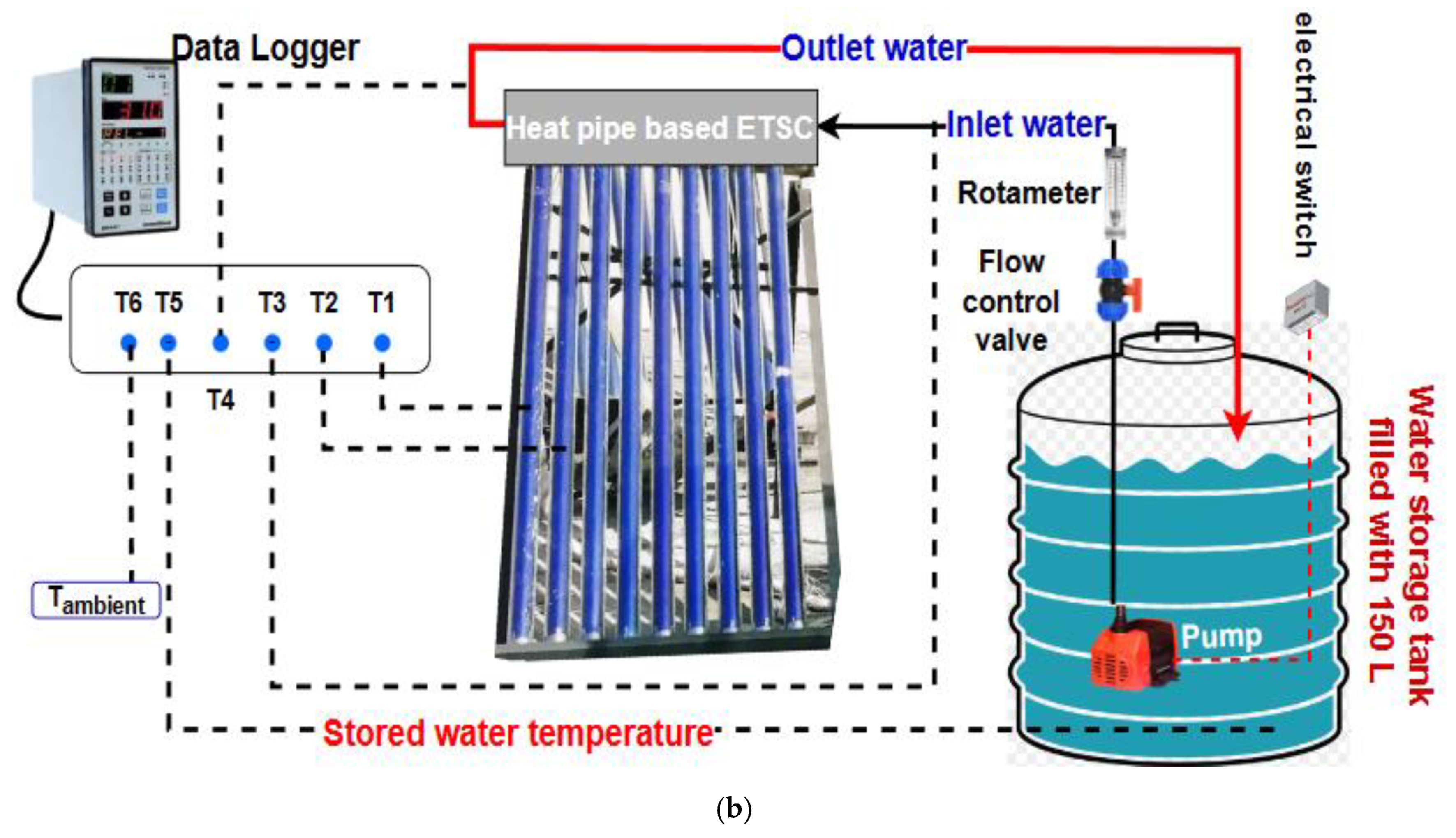
2.2. Experimental Setup Description

Figure 1b depicts the schematic of the test setup. The developed SWH system was tested under outdoor conditions on the rooftop of the SMVDU, Jammu, India (32.9418° N, 74.9541° E). The designed system was tilted at 45° (optimum) in the north–south direction. The palmitic acid was filled into the annulus space between the absorber sides of the tube. Generally, PCMs suffer from low heat conductivity, which affects the transmission of heat from the PCM to the heat pipe. To overcome this issue, an aluminum fin was attached to the heat pipe in order to increase the heat transmission rate. The process of filling the tube with the PCM is described in the following section (See Figure 1a). Firstly, the PCM was melted with the help of a hot plate and then with the help of a beaker, the liquified PCM was directly filled into the evacuated tube with 75% of that total volume. As per the liquified density, 1.9 kg of the selected palmitic acid was filled into each tube. The proposed SWH system was made of nine thermosyphon heat pipes with tubes.
The experimental investigation was conducted at 20 LPH for clear and cloudy weather conditions. The water was circulated through a pump and its flow rate was measured via a highly calibrated rotameter. The output water was collected inside the insulated tank and recirculated to achieve a high degree of hot water for further utilization. Six calibrated thermocouples were positioned at different locations within the proposed system to observe the temperatures of various places. The thermocouples were arranged from T1 to T6 and are presented in Table 2 with their suitable locations. In addition, detailed technical information regarding the test setup and its measuring instruments is presented in Table 3.

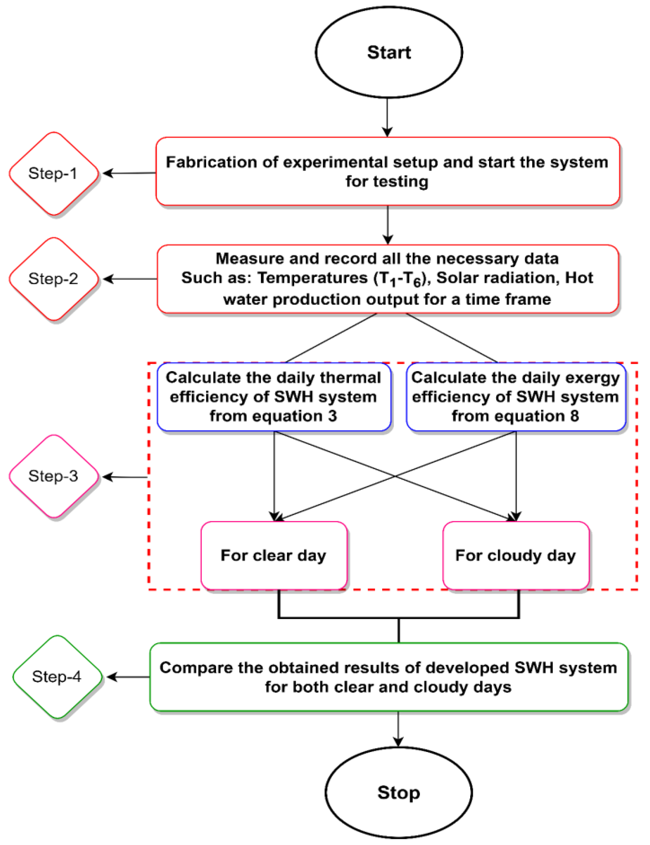
2.3. Experimental Methodology

This study investigated the energetic and exergetic outputs of a HP-based ETC–SWH system with PCM (palmitic acid) at flow rate of 20 LPH for clear and cloudy weather conditions in Jammu, India. A part of the incoming solar energy striking on the area of the collector was stored by the PCM. The remaining part of the solar energy was collected by the heat pipe’s working fluid. The heated fluid moved towards the condenser section and released its heat to the circulating fluid (water) through the manifold. There were two test conditions: Test 1, at 20 LPH for clear weather conditions, and Test 2, at 20 LPH for cloudy weather conditions. For more accurate results, the experimental setup was operated twice with the same environmental conditions for each test. Initially, the setup was covered with a black sheet; at 7:00 a.m., the cover was removed to operate the experimental setup. In the early morning, the solar radiation was very low, due to which the system output fluctuated. To avoid this problem, the system was allowed to stabilize from 7:00 a.m. to 8:00 a.m.; after that, the real operation was started. The experiment was conducted from 8:00 a.m. until 6:00 a.m., the morning of the next day, for almost 22 h. In addition, the flow diagram (See Figure 2) depicts the methodology adopted in order to assess the various output parameters of the developed SWH system.

3. Heat Transfer and Thermal Performance Analysis

This section discusses the assessment of heat transmission/losses and the thermal output of designed collector. Figure 3 depicts the thermal network and heat transmission assessment of the PCM-integrated heat-pipe-based ETSC.

3.1. Heat Transfer/Thermal Losses Assessment

The overall losses of heat transmission for the PCM-filled HP-based ETSC are described in this part of the study. A fraction of the solar energy collected as thermal energy at the surface of the selective coating was dissipated into the atmosphere through radiative heat transmission from the absorber to the outer glass tube, convection heat transmission via the atmospheric air, and radiative heat transmission from the outer tube to the atmosphere. The maximum heat losses from the absorber surface to the atmosphere are mainly decomposed into three mechanisms of heat transmission:
i. Coefficient of heat transmission by radiation from inner to outer side of the evacuated tube is given as follows [17,20]:
h o , i = σ ( T t , o 2 + T t , i 2 ) ( T t , o + T t , i ) 1 ϵ t , i + A i A o ( 1 ε t , o 1 )
ii. Coefficient of convection heat transmission via air velocity from outer surface of the evacuated tube is given as follows:
h t , w i n d = 5.7 + 3.8 v
iii. Coefficient of radiative heat transmission from outer surface of the tube to the ambient air can be written as follows:
h t , s k y = σ ϵ t , o ( T t , o 2 + T s k y 2 ) ( T t , o + T s k y )
Overall heat transmission (loss) coefficient can be written as follows:
U L = 1 A i ( 1 h o , i × A i + 1 ( h t , w i n d + h t , s k y ) × A o ) 1

3.2. Thermal Resistance for PCM Filled Heat Pipe Based ETSC

The thermal resistance from the selective coating surface of the collector to the working fluid inside the heat pipe is shown in Figure 3, which can be written as follows:
The heat resistance of the outer wall of the evaporator section:
R 1 = σ m π k h p d m L e
The heat resistance between the liquid and vapor of the evaporator:
R 2 = R T s 2 2 π R T s P v h f g 2 π d e L e
The heat resistance between the vapor and liquid of the HP-based ETSC:
R 3 = R T s 2 2 π R T s P v h f g 2 π d c L c
The heat resistance from the outer wall of the condenser:
R 4 = σ m π k h p d m L c
The heat resistance between the outer wall of the condenser and the flowing fluid (water):
R 5 = 1 h π d c L c

3.3. Energy Assessment

Energy assessment is used to interpret and analyze the output of thermal systems that have been developed. Their daily thermal efficiency (DTE) is calculated by dividing the daily useful energy gain (Quseful) by the incident solar energy (Qabsorbed) absorbed by the collector. The mathematical expression can be written as Equation (3) [21]:
Q u s e f u l = m ˙ w × C p , w × ( T w o T w i )
For a PCM-filled heat-pipe-based ETC–SWH system, some part of the incident solar energy absorbed by the PCM can be written as follows:
Q u s e f u l = m w × C p × Δ T + m L
The latent heat stored by the PCM can also be obtained using the following equation [22]:
Q l a t e n t = m [ C P S ( Δ T ) + λ L P C M + C p l ( Δ T ) ]
where λ is identified as the melting fraction of the PCM. This can be written as follows [23]:
λ = {     0                               T P C M < T S T s T P C M T s T l T S < T P C M < T m     1                               T m < T P C M }
The solar energy absorbed by collector can be written as follows:
Q a b s o r b e d = I T × A a p e r t u r e
Finally, the mathematical expression for the daily thermal efficiency can be written as follows:
η D T E = Q u s e f u l Q a b s o r b e d

3.4. Exergetic Assessment

Although the 1st law of heat talks about energy, there is no indication as to how much the efficiency of the thermal system has deteriorated. Using the 2nd law of thermodynamics, exergy analysis provides evidence pertaining to the system’s actual losses. In exergy analysis, the design of the system, its optimization, and the study of its thermal performance are all important considerations. To conduct an exergy assessment of the developed SWH system, the following set of equations, from (13) to (14), was used [24].
The average exergetic gain can be calculated by taking the net exergy over the collector manifold and dividing it by the number of systems [25]:
E x g a i n = E x o u t E x i n
The exergy at the outlet section of the manifold can be written as follows:
E x o u t = m ˙ w × C p , w × [ T w o T a m b ( 1 + T a m b l n ( T w o T a m b ) ) ]
The exergy at the inlet of the manifold can be written as follows:
E x i n = m ˙ w × C p , w × [ T w i T a m b ( 1 + T a m b l n ( T w i T a m b ) ) ]
For the developed systems, the average incident exergy can be calculated as follows:
E x s o l a r = I T × A a p e r t u r e × [ 1 4 3 ( T a m b T s u n ) + 1 3 ( T a m b T s u n ) 4 ]
Thus, the daily exergy efficiency should be obtained by dividing the average of the system’s exergy gain by the average of the incident exergy on the developed system [26]:
η D E X = E x o u t E x i n E x s o l a r

3.5. Uncertainty Study

The uncertainty analysis of the measuring components is examined in order to obtain the accuracy of the recorded data. Generally, a significant quantity cannot be expressed clearly, but relies on components that can be evaluated directly, e.g., Y = f (X1; X2; X3; X4…). The observed parameters, namely X1, X2, X3, X4,…, Xi have a randomly varying value, referred to as uncertainty [27]. This analysis identifies how the uncertainties associated with each calculated variable propagate into the measured amount value. The uncertainty analysis equation can be written as follows:
U z = i ( δ Y δ X i ) 2 U x i 2
For example, the uncertainty in the temperature sensors is ± 0.5 °C, whereas the uncertainty in the pyranometer is ± 1.5%, and the uncertainty in the rotameter is ± 2% of the standard deviation. As per the above equation, the uncertainty in the exergy and energy efficiencies varies between ± 0.45–0.9% and ± 1.5–2.5%.

4. Results and Discussions

The discussion starts with the variation in the solar radiation relative to time. Then, the variation in the useful thermal energy gain for the designed system relative to time is discussed. In addition, the effect of the PCM temperature inside the tube relative to time for clear and cloudy days is comprehensively explained. The next section discusses the variation in the exit and entry water temperature, along with the storage tank temperature, relative to time for both clear and cloudy days. Finally, the energetic, exergetic and heat transfer analysis results of the developed SWH system are explained and compared with each other in this study.

4.1. Heat Transfer Assessment for Developed Collector

In this study, COMSOL Multiphysics software 5.0 was used to estimate the thermal losses of a PCM-filled HP-based ETSC. The outer and inner tube temperatures of the developed collector were obtained using the Fourier law of heat conduction. The selected material for the evacuated tube was borosilicate glass, which had a conductivity of 1.13 W/m K. The boundary conditions of heat flux through the walls of the evacuated tube involved the system’s operation under steady-state heat conduction with inner and outer surface temperatures of T1 = 24 °C and T2 = 27 °C. For the heat transmission assessment of the heat pipe, copper with a thermal conductivity of 401 W/m K was selected. The boundary conditions of heat flux for the inner and outer surface temperatures were T1 = 51 °C and T2 = 51 °C. Table 4 shows the physical values of the geometrical and environmental parameters used in the heat transmission assessment of the designed collector. Figure 4 shows the heat transmission/thermal losses analysis of the PCM-filled heat-pipe-based ETSC. It also shows the temperature distribution and heat flux through the ET and the wall of the HP. The physical values of the various thermal resistance and overall heat transfer coefficients were calculated and are presented in Table 5. As per the results, the PCM-integrated heat-pipe-based ETC–SWH system has a low thermal resistance and a high thermal performance compared to the conventional ETC–SWH system.

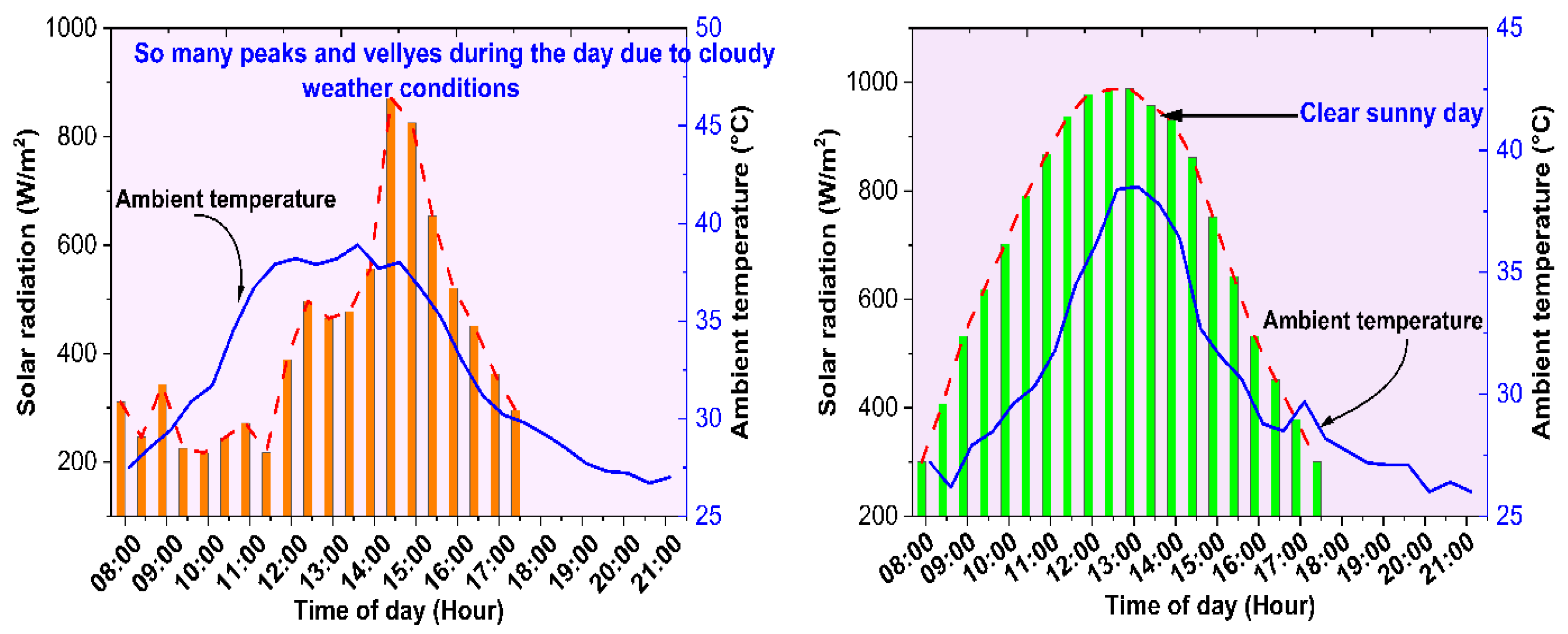
4.2. Variation of Solar Energy and Ambient Temperature for Clear and Cloudy Days

Figure 5 depicts the variation in the solar energy for both clear and cloudy test days. The solar radiation data were measured using a solar power meter at regular intervals of 30 min. The overall solar energy data trend for a clear day increased for a time period and reached to its maximum value at 12:45 p.m. After that, it decreased gradually. On a cloudy day, the solar radiation fluctuates constantly during the day whenever clouds hide the sun. The maximum fluctuation happened between 9:00 a.m. and 2:00 p.m. due to cloudy weather conditions with dense clouds. In addition, the ambient temperature variations relative to time for both test days are shown in Figure 5. It was seen that the ambient temperature on the cloudy test day fluctuated within the range of 26–38 °C, while on the sunny test day varied in the range of 26–40 °C. Heat losses are high during clear sunny days, so the maximum exergy efficiency is obtained from the developed collector.

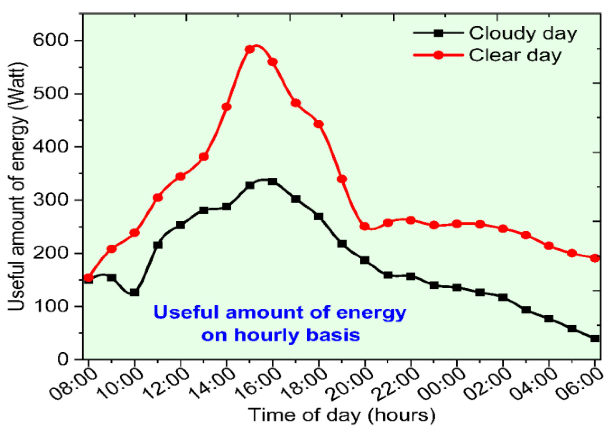
4.3. Variation of Thermal Energy Gain for a Clear and Cloudy Test Days

The disparities regarding the instantaneous thermal energy gain relative to time for both clear and cloudy test days at 20 LPH are revealed in Figure 6. It is shown that whenever the solar energy intensity is high, the excess thermal energy is absorbed and collected as latent heat within the PCM. The stored heat controls the fluctuations that arise due to changes in weather conditions in conventional SWH systems. Furthermore, the trends observed regarding the useful energy gained by water for both climate conditions are quite similar. The stored energy in the PCM is discharged in order to heat the flowing fluid (water) during cloudy weather conditions, causing an increase in the outlet water temperature. Figure 6 reveals that the useful amount of energy stored by water on a clear-skied day is more than on a cloudy day. The daily stored energy of water for the developed SWH system is higher than the heat energy collected by the PCM in the first half of the operating session. The most useful energy peak is achieved around 3:00 p.m. on both test days. The maximum usable amounts of energy collected for the developed HP-based ETC–SWH system were 10.65 MJ and 8.52 MJ for clear and cloudy test days, respectively.
As we know, sufficient heat is absorbed by the PCM during clear sunny days and is released in cloudy/night/low-sunshine hours in order to heat the flowing fluid (water). However, this phenomenon was affected due to the poor heat conductivity of the PCM and the decreased heat transfer rate. Aluminum fins of annular shape were used to overcome the issue of the low heat conductivity of the PCM and to improve the overall thermal output of the system. Figure 7 shows another important parameter (liquid fraction) of the PCM used to ensure its complete charging and discharging during phase change. Figure 7 reveals that the PCM was completely melted for both test days. The complete melting of the PCM occurred around noon on the clear sunny day, whereas the PCM was completely melted around 3:30 p.m. on the cloudy test day. It is evident that the developed system can be operated during low-intensity solar radiation at sunrise and sunset and during intermittent cloudy conditions.

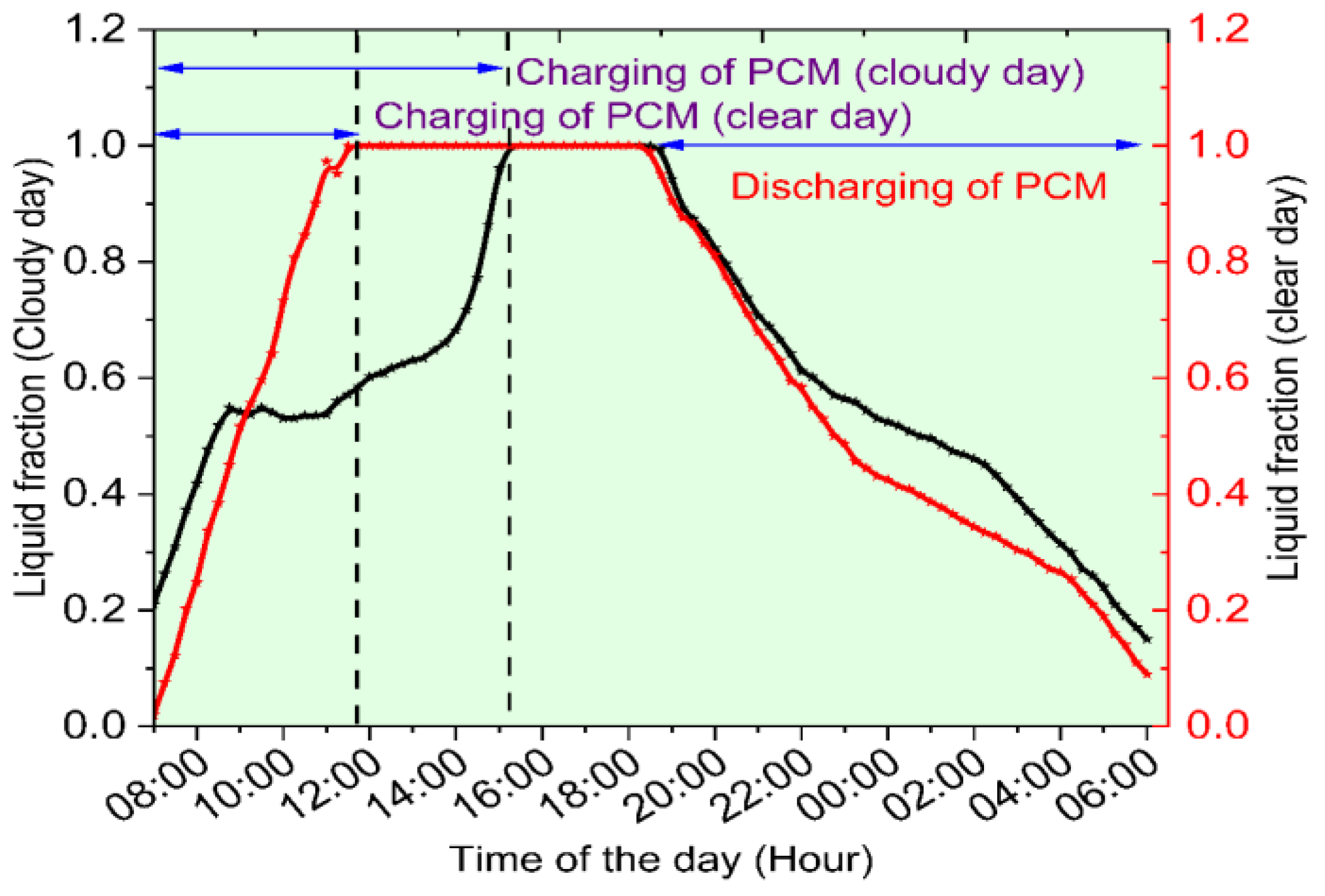
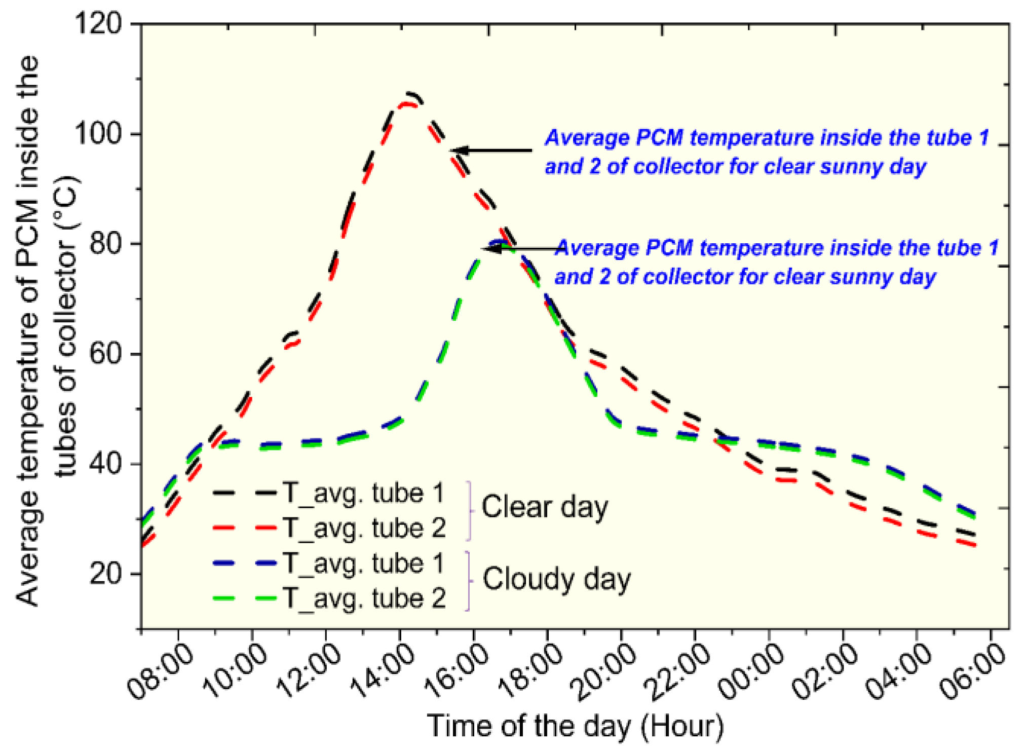
4.4. Variation of Average PCM Temperature with Time for Clear and Cloudy Test Days

Figure 8 depicts the changes in the PCM temperature inside the ET for both clear and cloudy days. It can be observed that the heat absorbed by the PCM fluctuates due to variations in the mass flow rate of the working fluid. The trends observed regarding the average PCM temperature inside the tube for both clear and cloudy weather conditions are similar.
The maximum PCM temperatures were 112 °C (Tube-1) and 108 °C (Tube-2) at somewhere around 3:00 p.m. for the developed system on a clear day. In contrast, the maximum temperatures of the PCM on a cloudy day were 97 °C (Tube-1) and 90 °C (Tube-2). It can be observed that the best thermal output was achieved on a cloudy day during the simultaneous mode of operation. Moreover, it was found that through the charging cycle, in the first half, the highest temperature in the evacuated tube was obtained in the upper portion, while the lowest temperature was achieved in the bottom part of the tube. On the other hand, during the discharging process, the reverse happened. The sudden variation in temperature during the discharging process reflects the liquid PCM’s conversion into a solid form. It releases latent heat, which occurs at a specific temperature range. The discharging trend of the PCM for both test days is identical. It indicates a uniform temperature variation inside the tube. The temperature variation of the PCM throughout the day shows that the developed system has an extended phase-change period compared to the standard SWH system.

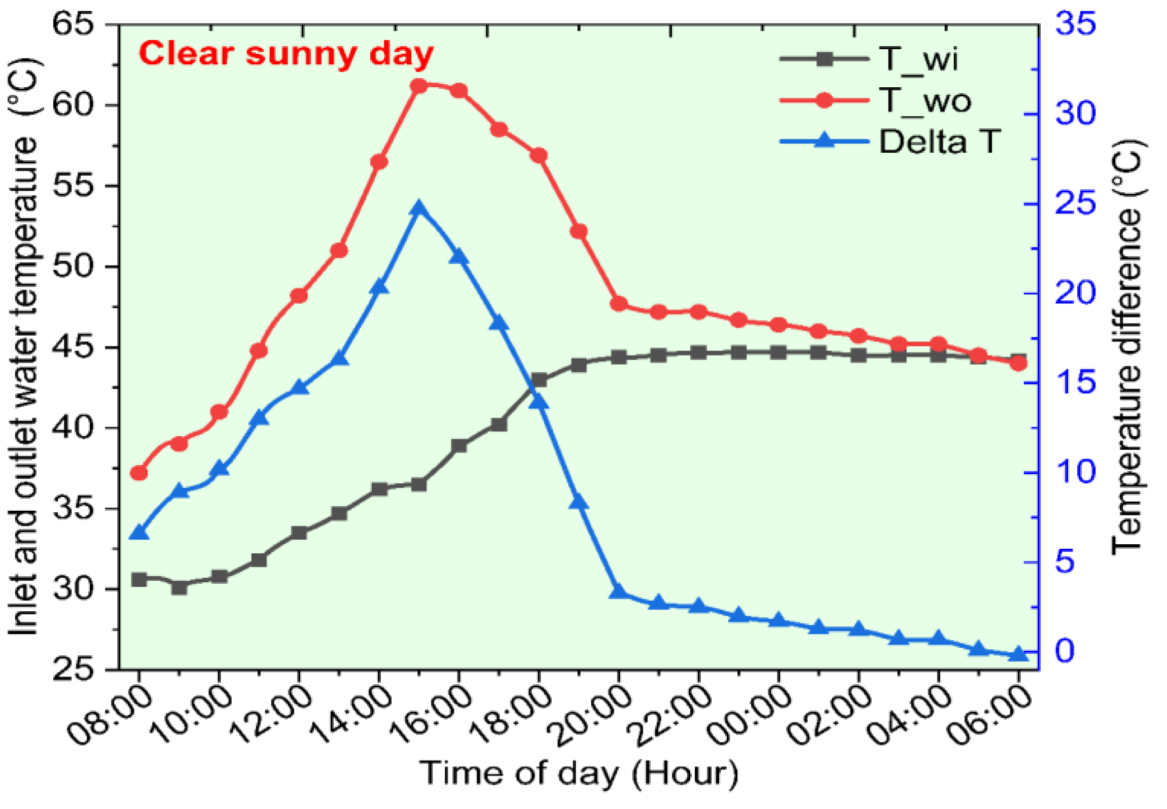
4.5. Variation in Outlet/Inlet Water Temperature for Both Clear and Cloudy Test Days

The change in the inlet (Tw,i) and outlet (Tw,o) water temperature, along with the water storage tank temperature (Ttank)for both test days from 8:00 a.m. to 6 a.m., is discussed in this section. The variation in the outlet and inlet water temperature, along with the stored water temperature relative to the time, are presented in Figure 9, Figure 10 and Figure 11. It was found that the outlet temperature of water on a clear day is higher than that on a cloudy day during the charging phase and discharging phase. However, as the PCM’s average temperature in the tube for a clear sunny day is higher, it transfers more heat to water, increasing the exit temperature of the water. For cloudy day conditions, the heat absorbed by the PCM throughout the day (charging process) is transferred to the circulating working fluid (water) in the evening at low-sunshine hours (discharging process). It can be seen that the heat stored in the PCM can be effectively used for heating the water in late-night hours. Therefore, the PCM-integrated ETC–SWH system is capable of supplying hot water (more than 40°C) for night hours. It is the main requirement of any SWH system to maintain a continuous supply of hot water in cloudy/low-sunshine hours. At 20 LPH, the maximum outlet temperatures of the water were 62.2 °C and 50.4 °C (around 3:00 p.m.) for clear and cloudy days, respectively. Here, the maximum ∆T values were 25.5 °C and 14.4 °C for clear and cloudy conditions, respectively. Moreover, in a particular instance, the inlet and outlet temperatures of the water are the same because the PCM becomes solid after releasing all the latent heat stored within it.
Figure 11 shows the stored water temperature for clear and cloudy weather conditions. It was observed that the temperatures of the stored water for the designed SWH system were 46.2 °C and 41.4 °C at 6:00 a.m. in the next morning for both climate conditions. These are pretty high-water temperatures that can be used for household applications such as bathing, washing, clothing, etc. Therefore, the developed system can be seen as a viable option with which to meet the fluctuation in demand and supply of hot water.

4.6. Daily Energetic and Exergetic Efficiencies of HP-Based ETC–SWH

In this section, the daily average energetic and exergetic outputs of the developed HP–ETC-based SWH system obtained using solar radiation data and other observed parameters are shown in Figure 10. The average daily energetic and exergetic outputs of the developed SWH system were 76.57% and 79.64%, and 2.37% and 1.38%, respectively, for clear and cloudy day conditions. The cloudy day’s daily average energy efficiency was higher than that of the clear day due to the minimal amount of heat lost to the surroundings. It was found that the energy efficiency increased relative to the time until 05:30 p.m. for both weather conditions. After that, the system’s energy efficiency was not taken into account due to the absence of solar energy. The designed system’s energy efficiency was much higher than the conventional system. The results of previously published studies were compared with the current study, as shown in Table 6.
Finally, it was discovered that the daily average exergetic output is always less than the daily energy output because exergy cannot be restored once it has been destroyed (See Figure 12). However, the exergy assessment of the proposed system considers all losses of the SWH system, as well as factors that could not be changed. The outcomes obtained from the present study also highlight the various advantages of the developed system over basic SWH systems. For example, (i) due to aluminum fin outside the heat pipe, the rate of heat transmission from the heat pipe to the PCM increased during the simultaneous mode of operation; (ii) the problem of overheating within the heat pipes inside the tube was avoided; and (iii) the instant fluctuations in the solar energy data relating to the thermal output of the SWH system were minimized. Overall, the results showed that filling the tube with PCM for heat energy storage and increasing the rate of heat transmission are advantageous. However, the designed PCM-integrated SWH system needs more studies regarding its limited energy recovery at night hours/low-sunshine hours.

5. Conclusions

In this study, energetic and exergetic assessments, along with an evaluation of the heat losses of a PCM-filled heat-pipe-based ETC–SWH system, have been performed. Here, palmitic acid is utilized as the heat storage material inside the evacuated tubes of the collector. The main benefit of filling the tubes with a PCM is minimizing the need for extra space. The results revealed that the integration of a PCM with the ETC–SWH system not only maintained the hot water demand in late night/low-sunshine hours, but also improved the overall thermal output of the proposed system. The tests were conducted in the Indian climate conditions of Jammu on clear and cloudy days at 20 LPH. The following conclusions are as follows:
  • The proposed collector obtained a better thermal output than conventional systems (validated by other studies). This happened because of the storage of excess heat energy in the PCM during the daytime, which was utilized in late-night hours.
  • The calculated overall heat transfer coefficients (UL) found via COMSOL Multiphysics for clear and cloudy days were 0.75 and 0.72 W/m2 K, respectively. This shows that losses were at a minimum for cloudy weather conditions.
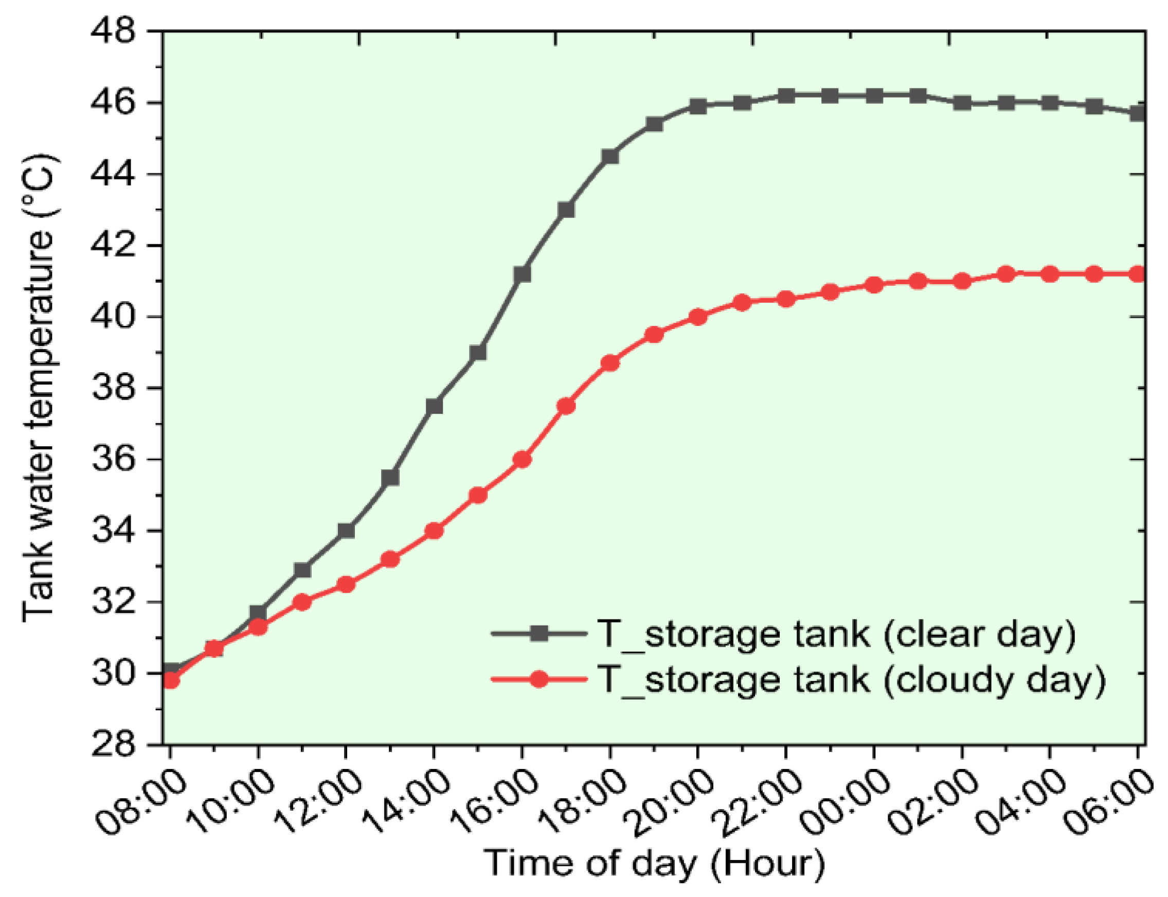
  • The daily useful amounts of energy collected by water were 10.65 MJ and 8.52 MJ for clear and cloudy test days. The maximum water outlet temperatures were 62.2 °C and 50.4 °C, and the storage tank temperatures were 45 °C and 41 °C, respectively, for clear and cloudy day conditions.
  • The daily average energetic and exergetic outputs of the developed collector for the clear test day were found to be 76.57% and 2.37%, whereas the corresponding values for the cloudy test day were 79.64%, and 1.38%, respectively.
  • The daily thermal output of the developed collector was higher for a cloudy test day compared to a clear day, which means that the developed system can be considered as a feasible option for on-demand hot water production during partially overcast weather conditions.

Author Contributions

S.K.P.: Conceptualization, Methodology, Data curation, Writing—Original draft preparation. V.V.T.: Visualization, Supervision, Data curation. K.C.: Validation, Reviewing and Editing. A.K.P.: Validation, Reviewing and Editing. A.S.: Reviewing and Editing and A.M.A.: Validation, Reviewing and Editing. All authors have read and agreed to the published version of the manuscript.

Funding

The author(s) received no financial support for the research, authorship, and/or publication of this article.

Informed Consent Statement

Not applicable.

Data Availability Statement

Data will be available on request.

Conflicts of Interest

The authors declare that they have no known competing financial interests or personal relationships that could have appeared to influence the work reported in this paper.

Nomenclature

Cp,wWater-specific heat (J/kg K)
ExgainExergy gain (J)
ExoutExergy at the outlet (J)
ExinExergy at the inlet (J)
ExsolarIncident solar exergy (J)
QusefulUseful amount of energy (W)
QabsorbedEnergy absorbed by collector (W)
mwMass flow rate of water (LPH)
ITSolar radiation (W/m2)
AapertureAperture area (m2)
σStefan–Boltzmann constant (W/m2 K4)
AiInner surface area of tube (m2)
AoOuter surface area of tube (m2)
εt,iEmissivity of inner surface
εt,oEmissivity of outer surface
Le and LcLength of evaporator and condenser (m)
khpThermal conductivity of copper (W/m K)
de and dcDiameter of evaporator and condenser (m)
Tt,oTemperature of outer surface (°C)
Tt,iTemperature of outer surface (°C)
ηDTEDaily thermal efficiency
ηDEXDaily exergy efficiency
Abbreviations
DSCDifferential scanning calorimetry
ETEvacuated tube
ETSCEvacuated tube solar collector
LHSLatent heat storage
TESThermal energy storage
PCMPhase change material
LPHLiter per hour
SWHSolar water heater
MJMega joule
HPHeat pipe

References

  1. Gao, Y.; Fan, R.; Zhang, X.; An, Y.; Wang, M.; Yu, Y. Thermal performance and parameter analysis of a U-pipe evacuated solar tube collector. Sol. Energy 2014, 107, 714–727. [Google Scholar] [CrossRef]
  2. Goel, V.; Hans, V.; Singh, S.; Kumar, R.; Pathak, S.K.; Singla, M.; Bhattacharyya, S.; Almatrafi, E.; Gill, R.; Saini, R. A comprehensive study on the progressive development and applications of solar air heaters. Sol. Energy 2021, 229, 112–147. [Google Scholar] [CrossRef]
  3. Ahmed, S.F.; Khalid, M.; Vaka, M.; Walvekar, R.; Numan, A.; Rasheed, A.K.; Mubarak, N.M. Recent progress in solar water heaters and solar collectors: A comprehensive review. Therm. Sci. Eng. Progress 2021, 25, 100981. [Google Scholar] [CrossRef]
  4. Naik, B.K.; Premnath, S.; Muthukumar, P. Performance comparison of evacuated U-tube solar collector integrated parabolic reflector with conventional evacuated U-tube solar collector. Sadhana—Acad. Proc. Eng. Sci. 2021, 46, 137. [Google Scholar] [CrossRef]
  5. Ahmed, M.A.; Rofaiel, I.Y.; Essa, M.A. Experimental study for the performance of an integrated solar collector water heater based on helical fins heat pipes using phase changing material. Egypt. J. Eng. Sci. Technol. 2020, 30, 22–38. [Google Scholar] [CrossRef]
  6. Li, C.; Zhang, B.; Xie, B.; Zhao, X.; Chen, J.; Chen, Z.; Long, Y. Stearic acid/expanded graphite as a composite phase change thermal energy storage material for tankless solar water heater. Sustain. Cities Soc. 2019, 44, 458–464. [Google Scholar] [CrossRef]
  7. Elbrashy, A.; Abou-Taleb, F.; El-Fakharany, M.K.; Essa, F.A. Experimental study of solar air heater performance by evacuated tubes connected in series and loaded with thermal storage material. J. Energy Storage 2022, 54, 105266. [Google Scholar] [CrossRef]
  8. Wu, W.; Wang, X.; Xia, M.; Dou, Y.; Yin, Z.; Wang, J.; Lu, P. A novel composite PCM for seasonal thermal energy storage of solar water heating system. Renew. Energy 2020, 161, 457–469. [Google Scholar] [CrossRef]
  9. Chopra, K.; Tyagi, V.V.; Pandey, A.K. Thermodynamic and techno-economic analysis of heat pipe ETC water heating system for Indian composite climate: An experimental approach. J. Therm. Anal. Calorim. 2020, 139, 1395–1407. [Google Scholar] [CrossRef]
  10. Abokersh, M.H.; El-Morsi, M.; Sharaf, O.; Abdelrahman, W. On-demand operation of a compact solar water heater based on U-pipe evacuated tube solar collector combined with phase change material. Sol. Energy 2017, 155, 1130–1147. [Google Scholar] [CrossRef]
  11. Shafieian, A.; Khiadani, M.; Nosrati, A. Thermal performance of an evacuated tube heat pipe solar water heating system in cold season. Appl. Therm. Eng. 2019, 149, 644–657. [Google Scholar] [CrossRef]
  12. Pawar, V.R.; Sobhansarbandi, S. Heat transfer enhancement of a PCM-porous metal-based heat pipe evacuated tube solar collector: An experimental study. Sol. Energy 2023, 251, 106–118. [Google Scholar] [CrossRef]
  13. Ben Khedher, N. Experimental Evaluation of a Flat Plate Solar Collector Under Hail City Climate. Eng. Technol. Appl. Sci. Res. 2018, 8, 2750–2754. [Google Scholar] [CrossRef]
  14. Alshukri, M.J.; Eidan, A.A.; Najim, S.I. Thermal performance of heat pipe evacuated tube solar collector integrated with different types of phase change materials at various location. Renew. Energy 2021, 171, 635–646. [Google Scholar] [CrossRef]
  15. Feliński, P.; Sekret, R. Effect of PCM application inside an evacuated tube collector on the thermal performance of a domestic hot water system. Energy Build. 2017, 152, 558–567. [Google Scholar] [CrossRef]
  16. Bazri, S.; Badruddin, I.A.; Naghavi, M.S.; Seng, O.K.; Wongwises, S. An analytical and comparative study of the charging and discharging processes in a latent heat thermal storage tank for solar water heater system. Sol. Energy 2019, 185, 424–438. [Google Scholar] [CrossRef]
  17. Hlaing, S.; Soe, M.M. Design Calculation and Heat Transfer Analysis of Heat Pipe Evacuated Tube Solar Collector for Water Heating. Int. J. Sci. Eng. Technol. Res. 2014, 3, 2606–2611. [Google Scholar]
  18. Wu, W.; Dai, S.; Liu, Z.; Dou, Y.; Hua, J.; Li, M.; Wang, X.; Wang, X. Experimental study on the performance of a novel solar water heating system with and without PCM. Sol. Energy 2018, 171, 604–612. [Google Scholar] [CrossRef]
  19. Chopra, K.; Tyagi, V.; Pandey, A.; Ma, Z.; Ren, H. Energy, exergy, enviroeconomic & exergoeconomic (4E) assessment of thermal energy storage assisted solar water heating system: Experimental & theoretical approach. J. Energy Storage 2021, 35, 102232. [Google Scholar] [CrossRef]
  20. Pathak, S.K.; Tyagi, V.; Chopra, K.; Kalidasan, B.; Pandey, A.; Goel, V.; Saxena, A.; Ma, Z. Energy, exergy, economic and environmental analyses of solar air heating systems with and without thermal energy storage for sustainable development: A systematic review. J. Energy Storage 2023, 59, 106521. [Google Scholar] [CrossRef]
  21. Eltaweel, M.; Abdel-Rehim, A.A. Energy and exergy analysis of a thermosiphon and forced-circulation flat-plate solar collector using MWCNT/Water nanofluid. Case Stud. Therm. Eng. 2019, 14, 100416. [Google Scholar] [CrossRef]
  22. Douvi, E.; Pagkalos, C.; Dogkas, G.; Koukou, M.K.; Stathopoulos, V.N.; Caouris, Y.; Vrachopoulos, M.G. Phase change materials in solar domestic hot water systems: A review. Int. J. Thermofluids 2021, 10, 100075. [Google Scholar] [CrossRef]
  23. Elarem, R.; Alqahtani, T.; Mellouli, S.; Aich, W.; Ben Khedher, N.; Kolsi, L.; Jemni, A. Numerical study of an Evacuated Tube Solar Collector incorporating a Nano-PCM as a latent heat storage system. Case Stud. Therm. Eng. 2021, 24, 100859. [Google Scholar] [CrossRef]
  24. Saxena, G.; Gaur, M.K. Energy, exergy and economic analysis of evacuated tube solar water heating system integrated with heat exchanger. Mater. Today Proc. 2020, 28, 2452–2462. [Google Scholar] [CrossRef]
  25. Ersöz, M.A. Effects of different working fl uid use on the energy and exergy performance for evacuated tube solar collector with thermosyphon heat pipe. Renew. Energy 2016, 96, 244–256. [Google Scholar] [CrossRef]
  26. Singh, I.; Vardhan, S. Energy, exergy, environmental and economic (4E) analysis of evacuated tube solar collector with helical coils. J. Mech. Sci. Technol. 2022, 36, 5801–5808. [Google Scholar] [CrossRef]
  27. Abo-Elfadl, S.; Yousef, M.S.; Hassan, H. Energy, exergy, and enviroeconomic assessment of double and single pass solar air heaters having a new design absorber. Process. Saf. Environ. Prot. 2021, 149, 451–464. [Google Scholar] [CrossRef]
  28. Essa, M.A.; Rofaiel, I.Y.; Ahmed, M.A. Experimental and Theoretical Analysis for the Performance of Evacuated Tube Collector Integrated with Helical Finned Heat Pipes using PCM Energy Storage. Energy 2020, 206, 118166. [Google Scholar] [CrossRef]
Figure 1. (a) The PCM filling process (b) schematic of test setup.
Sustainability 15 09780 g001aSustainability 15 09780 g001b
Figure 2. Steps to be followed for experimental investigation.
Sustainability 15 09780 g002
Figure 3. (A) Thermal network diagram and (B) heat transmission assessment of heat-pipe-based ETSC.
Sustainability 15 09780 g003
Figure 4. Heat transfer/thermal losses analysis of PCM-integrated heat-pipe-based ETSC.
Sustainability 15 09780 g004
Figure 5. Solar radiation variation for cloudy and clear days.
Sustainability 15 09780 g005
Figure 6. Useful thermal energy gained by the system for both clear and cloudy weather conditions.
Sustainability 15 09780 g006
Figure 7. Variation in PCM liquid fraction relative to time for both test days.
Sustainability 15 09780 g007
Figure 8. Variation in PCM temperature inside the tubes of the collector for both test days.
Sustainability 15 09780 g008
Figure 9. Variation in the outlet, inlet and tank temperature for cloudy day conditions.
Sustainability 15 09780 g009
Figure 10. Changes in the outlet, inlet and tank temperature for clear day conditions.
Sustainability 15 09780 g010
Figure 11. Stored water temperature variation relative to time for both test days.
Sustainability 15 09780 g011
Figure 12. Daily energetic and exergetic efficiencies of the developed SWH system for both clear and cloudy test days.
Sustainability 15 09780 g012
Table 1. Thermophysical characteristics of palmitic acid (PCM).
S. No.PropertyValue in Range
1Latent heat of fusion204.93–205.52 kJ/kg
2Melting point (Tm)61.10–64.70 °C
3Specific heat (Cps and Cpl)2.20–2.48 kJ/kg °C
4Heat conductivity 0.25 W/m K
5Density of material (solid and liquid)0.85–0.89 g/cm3
Table 2. Description of the locations of the several thermocouples in the SWH system.
S. No.Notation of TemperatureTemperature with Their Respective Position (°C)
1T1Average temperature of PCM inside tube 1
2T2Average PCM temperature inside tube 2
3T3Temperature of the water at inlet
4T4Temperature of the water at outlet
5T5Stored water temperature
6T6Ambient temperature
Table 3. Specifications of the experimental setup.
S. No.SpecificationsValue/Material
1Evacuated tube length1800 mm
2Glass materialBorosilicate glass
3Thickness of glass2–3 mm
4Absorptivity of absorber tube>92%
5Emissivity of absorber tube<8%
6Heat pipe materialCopper
7Condenser section length63.5 mm
8Evaporator section length1600 mm
9Temperature range of RTDs−50 °C to 550 °C
10Submersible pump flow range0–2.6 LPM
11Rotameter flow rate range0–1.6 LPM
Table 4. Geometrical parameters of the PCM-filled heat-pipe-based ETSC.
Physical ParametersSymbolValue
Ambient temperatureTa24 °C
Wind velocityv0.8 m/s
Transmissibility0.85
Absorptivityα0.93
Outer and inner tube emission coefficient ϵ t , o   and   ε t , i 0.9
Outer and inner tube reflection coefficient ρ o   and   ρ i 0.14 and 0.08
Table 5. Thermal resistance/losses for PCM-integrated heat-pipe-based ETSC.
Heat-Pipe-Based ETSCRouter tube-amb. (m2K/W)Rinner to outer glass
(m2K/W)
Rheat pipe-inner glass (m2K/W)UL
(W/m2 K)
∑Rheat pipe
(K/W)
Test 1 (clear day)0.0561.683.7 × 10−40.753.91
Test 2 (cloudy day)0.0541.644.0 × 10−40.723.87
Table 6. Various experimental results compared with the present study.
ResearcherMass Flow RateDaily Average Energy Efficiency
Chopra et al. [19]16 LPH75.44%
Essa et al. [28]20 LPH52.20%
Present study20 LPH76.57% (Clear day) and 79.64% (Cloudy day)
Disclaimer/Publisher’s Note: The statements, opinions and data contained in all publications are solely those of the individual author(s) and contributor(s) and not of MDPI and/or the editor(s). MDPI and/or the editor(s) disclaim responsibility for any injury to people or property resulting from any ideas, methods, instructions or products referred to in the content.

