Abstract
Although conventional hydraulic fracturing techniques have revolutionized shale gas development, they have raised concerns regarding water management and environmental impacts. This research introduces an innovative step-rectangular pulse hydraulic fracturing method to optimize water usage and reduce environmental hazards in shale gas extraction. The method involves the application of lower-energy fluid in a step-rectangular pulse pattern, which results in higher pressures, more intricate fractures, and improved water management. A comprehensive analysis of the propagation and attenuation characteristics of this technique is conducted using a combination of a two-dimensional pulse transient flow equation with damping, software numerical simulations, and theoretical analysis. The study reveals that the step rectangular pulse hydraulic fracturing method offers superior pressurization and more complex fracture networks in shale reservoirs while lowering water consumption by 20% less than conventional methods and increasing shale gas production by 12%. Through identifying optimal pulse parameters, this research provides valuable guidance for field implementation, promoting efficient water management and environmental sustainability in hydraulic fracturing operations. This novel approach to hydraulic fracturing has the potential to significantly advance the industry’s efforts to address water management challenges and mitigate environmental risks associated with shale gas extraction.
1. Introduction
Oil and gas production companies frequently use hydraulic fracturing treatment (HFT) to extract unconventional oil and gas, injecting a fluid to create new hydraulic fractures in the reservoir [1,2,3,4,5,6]. These new fractures connect to the existing natural fractures to form a complex fracture network. When the fracturing fluid is injected into the reservoir using a high-pressure, high-flow pump, the reservoir develops primary hydraulic fractures, a limited number of branch fractures, and localized stress concentrations. This process is conventionally based on a procedure known as pulsating hydraulic fracturing (PHF). PHF allows for the creation of a reservoir with a uniform fracture network that efficiently increases oil and gas migration and extraction [7,8].
However, previous studies have shown that conventional hydraulic fracturing causes several environmental issues, mainly because of its significant water consumption. Millions of gallons of water are frequently utilized in a single fracturing operation, and a typical hydraulic fracturing operation for a horizontal gas well in a tight shale formation typically requires 3 to 5 million gallons of water over a 2- to 5-day period [9]. Due to the potential strain on local water supplies, particularly in arid areas, this high water consumption necessitates sophisticated water management techniques.
In response to the environmental concerns surrounding conventional hydraulic fracturing, researchers have developed an advanced method known as rectangular pulse hydraulic fracturing (RPHF). RPHF involves injecting the hydraulic fracturing fluid in a series of pulses instead of continuous injection. This pulsating approach generates a dynamic stress field within the shale formation, inducing a complex fracture network extending outward from the wellbore [10]. RPHF has been shown to reduce water consumption significantly [11,12] and enable the implementation of efficient techniques for water flow-back management [13]. The controlled fracture growth in RPHF can minimize the risk of fluid migration and groundwater contamination and lessen the environmental risks associated with conventional hydraulic fracturing [14]. Moreover, the reduced volume of fracturing fluid required in RPHF leads to more effective water management and a more salient mitigation of the risk of surface water contamination by reducing the volumes of flow-back and produced water. These advancements in water management are crucial for sustainable shale gas exploitation and careful consideration of environmental concerns.
The primary objective of this paper is to provide a comprehensive comparison between traditional hydraulic fracturing and rectangular pulse hydraulic fracturing in terms of the amount of fluid consumed during a hydraulic fracturing operation, as shown in Figure 1. In doing so, we discuss the critical differences in water consumption, fracture efficiency, and environmental impact between the two methods. In addition, we explore how these techniques contribute to developing shale gas resources and address the challenges of sustainable energy production, including water management, environmental risk assessment, fracture mechanics, and shale gas exploitation. Through this comparative analysis, we aim to demonstrate the potential advantages of RPHF as a more environmentally friendly and efficient alternative to conventional hydraulic fracturing, highlighting its potential role in shaping the future of shale gas extraction. The following Figure 1 illustrates the cycle of water consumption during a hydraulic fracturing process [11].
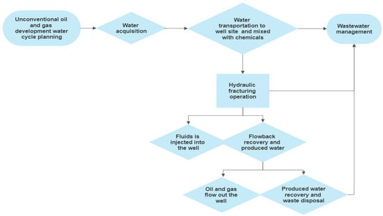
Figure 1.
The cycle of water consumption during a hydraulic fracturing operation.
2. Literature Review
Conventional hydraulic fracturing, also known as “frac jobs” or simply “fracking,” is a widely used technique for extracting unconventional natural gas, particularly shale gas [15]. This method has played a crucial role in boosting the production of domestic energy resources and transforming the landscape of energy production. The process involves the following steps: well preparation, fluid, and proppant selection, the fracturing process, and water flow-back [11].
Conventional hydraulic fracturing requires a substantial amount of water, with estimates ranging from 7000 to 18,000 cubic meters per well [11]. The water demand varies depending on factors such as the depth and length of the well, the number of fracturing stages, and the specific targeted geological formation. Water sourcing and transportation can present logistical challenges and significant demands on local water resources [16]. After fracturing, some of the injected fluid returns to the surface as flow-back water. This water contains chemicals from the fracturing fluid, salts, heavy metals, and naturally occurring radioactive materials resulting from shale formation [13]. Moreover, the shale formation may produce water, known as “produced water”, with similar constituents [17]. Managing flow-back and produced water is critical to hydraulic fracturing operations since improper handling can lead to environmental contamination [18].
Rectangular Pulse Hydraulic Fracturing (RPHF) is an advanced hydraulic fracturing method that offers several improvements over conventional techniques [10]. The method aims to reduce water consumption, increase fracture efficiency, and minimize environmental impacts. RPHF involves injecting the hydraulic fracturing fluid through a series of pulses instead of the continuous injection used in conventional hydraulic fracturing [10].
The RPHF process begins with designing and planning the pulse sequence. Engineers analyze the target shale formation’s properties, including its permeability, porosity, and stress distribution, to determine the optimal pulse shape, frequency, and duration. This information is then used to develop a customized pulse injection strategy tailored to the specific reservoir. To conduct pulse injection, specialized injection equipment is required; this equipment can generate high-pressure fluid pulses with precise control over pulse shape, frequency, and duration [19]. The pulse injection system is typically composed of high-pressure pumps, accumulators, and control valves, which are all managed by a computerized control system; then, the hydraulic fracturing fluid is pumped into the wellbore through a sequence of pulses [10]. These pulses generate a dynamic stress field in the shale formation, inducing complex fracture networks that extend outward from the wellbore [18]. The pulsating injection creates more controlled fracture growth, leading to enhanced reservoir stimulation, improved gas recovery, and reduced water consumption [20]. Since the method relies on pulsating rather than continuous injection, the overall volume of hydraulic fracturing fluid required is often significantly lower. Studies have shown that RPHF can reduce water consumption by up to 18% compared to conventional hydraulic fracturing [14]. Reduced water usage not only helps conserve valuable water resources but also decreases the logistical challenges associated with water sourcing and transportation, eventually yielding environmental benefits [21]. Controlled fracture growth can minimize the risk of fluid migration and groundwater contamination. Similarly, the reduced volume of fracturing fluid required leads to lower volumes of flow-back and produced water, simplifying water management, reducing the risk of surface water contamination, and enhancing shale gas recovery. Generating complex fracture networks and improving reservoir connectivity through RPHF are assumed to increase shale gas recovery rates and enhance gas production by up to 20% compared to conventional hydraulic fracturing [20]. The improved recovery rates can contribute to developing shale gas resources and promoting energy security [10,22].
Nevertheless, further research and development are necessary to optimize the RPHF process and fully understand its long-term implications for reservoir performance and environmental sustainability. The primary objective of this paper is to provide a comprehensive comparison between standard hydraulic fracturing and rectangular pulse hydraulic fracturing by shedding light on the critical differences between the two methods in terms of water consumption, fracture efficiency, and environmental impact. Another objective is to explore how these techniques contribute to the development of shale gas resources and address the challenges of sustainable energy production. Through this comparative analysis, we demonstrate the potential advantages of RPHF as a more environmentally friendly and efficient alternative to conventional hydraulic fracturing, highlighting its potential role in shaping the future of shale gas extraction.
3. Methodology
Mathematical models play a crucial role in understanding and optimizing hydraulic fracturing processes. These models help predict fracture propagation, fluid flow, and proppant transport in the reservoir, eventually leading to more efficient and environmentally friendly operations. This section will briefly discuss some of the primary mathematical models used to analyze hydraulic fracturing [19].
This research is based on the linear elastic fracture mechanics (LEFM) Model by Abaqus software; the LEFM model is based on the principles of linear elastic fracture mechanics and is widely used for predicting fracture geometry and propagation in hydraulic fracturing processes [19,23]. This model assumes the rock is an elastic, homogeneous, and isotropic medium. The stress intensity factor (SIF), which characterizes the stress field near the fracture tip, determines the fracture propagation rate and direction. The LEFM model provides valuable insights into the mechanical behavior of the rock during hydraulic fracturing. However, it has limitations when accounting for complex fluid-rock interactions and inelastic deformation. The input data for the target shale gas reservoir is provided by Sonatrach Company upon reasonable request and analyzed using Abaqus software for both methods (conventional and rectangular hydraulic fracturing),as presented in Table 1 [24]. The study area for this research is Salah, located in Algeria; its geographic information is displayed in Figure 2 [25].

Table 1.
Input Data for Abaqus Models (In-Salah Reservoir, Algeria).
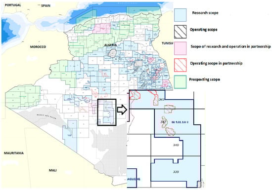
Figure 2.
The upstream hydrocarbon regions in Algeria [The National Agency for the Development of Hydrocarbon Resources].
Salah is a region in the central part of Algeria within the vast Sahara desert. It is located approximately 1200 km south of the capital city, Algiers. The region is known for its abundant shale gas reserves, making it a vital area for exploitation and hydraulic fracturing operations. The geological composition of In-Salah primarily consists of shale formations, which are rich in natural gas resources. These shale formations offer great potential for energy extraction, yet they pose unique challenges due to their low permeability [25]. Hence, hydraulic fracturing techniques play a crucial role in unlocking the trapped gas by creating fractures that enhance the permeability of the shale formations. Sweltering and dry conditions, with limited rainfall throughout the year, characterize the arid climate of In-Salah. Water scarcity is a significant concern in this region; thus, efficient water management is essential for maintaining sustainable development and lessening environmental impacts. Implementing advanced methods, such as rectangular pulse hydraulic fracturing, can contribute to enhanced water management and reduced water consumption, thereby addressing the challenges posed by water scarcity [25].
Linear elastic fracture mechanics (LEFM) is a theoretical framework that models the behavior of cracks in linearly elastic materials. In hydraulic fracturing, LEFM can predict fracture initiation and propagation in rock formations. Here, we will discuss the critical components of a LEFM model for hydraulic fracturing and the corresponding mathematical equations for Abaqus where forces are neglected [26]:
Stress Intensity Factor (SIF)
The stress intensity factor (K) is a fundamental concept in LEFM that quantifies the stress state near a crack or fracture tip. Mode I (opening) is the most relevant mode for hydraulic fracturing, as it involves the opening of fractures due to fluid pressure. Assuming minor strains in the context of solid mechanics allows for a linear relationship [27] and is given by Abaqus as:
Biot’s coefficient is represented by α while the dry elastic shear and bulk moduli are denoted by G and K, respectively. Additionally, the dry Young’s modulus is symbolized by E, and the dry Poisson’s ratio is represented by ν; ε represents the total strain or deformation tensor, and , represents the effective strain tensor. In the context of Abaqus, which is designed for fully saturated media, the Terzaghi effective stresses, denoted as σ′, are defined according to the following sources [27].
the constitutive equation becomes more straightforward when considering:
Fracture Toughness (KIC)
Fracture toughness KIC is a material property that characterizes a material’s resistance to crack propagation. It represents the critical value of the stress intensity factor at which a crack will begin to propagate. Fracture toughness can be approximated by the following equation [13,28]:
Energy Release Rate (G)
The energy release rate (G) is another important concept in LEFM and represents the rate at which energy is released as a crack propagates. The energy release rate can be related to the stress intensity factor and the fracture toughness through the following equation:
where is effective elastic modulus, as defined by:
Here, E is the elastic modulus of the rock, and ν is the Poisson’s ratio.
Crack propagation criteria in LEFM by Abaqus: The crack propagation criterion is typically based on the comparison between the stress intensity factor and the fracture toughness when KI > KIC crack propagation is expected to occur. Conversely, when KI < I < KIC, the crack will remain stable and will not propagate. The stress intensity factor is represented by K, and KI represents mode I for passage states, specifically for mode I loading conditions.
Application to hydraulic fracturing: Abaqus LEFM can be applied to hydraulic fracturing and rectangular pulse hydraulic fracturing methods by coupling the LEFM equations with fluid flow and rock deformation equations [10,29]. The fluid flow inside the fracture and the deformation of the rock surrounding the fracture can be modeled using the Navier–Stokes and linear elasticity equations, respectively [29]. These equations can then be coupled with the LEFM equations to predict the fracture propagation and overall efficiency of the hydraulic fracturing process [16].
3.1. Pore Fluid Flow
The porous medium where hydraulic fracturing occurs contains a fluid (usually water or brine) that fills the pore spaces between the solid grains. This fluid exerts pressure on the solid grains, which can affect the mechanical behavior of the porous medium. The continuity equation represents the conservation of mass in the pore fluid, and it considers the changes in fluid density, seepage velocity, and the porous medium’s deformation rate, assuming minor volumetric strains. The continuity equation for the pore fluid can be represented as [7,13,17]:
For the continuity equation involving pore fluid, the pore fluid seepage velocity is denoted by while Biot’s modulus and Biot’s coefficient are represented by M and α, respectively. Both poroelastic constants can be described by their respective identities [19,30,31]:
where in Abaqus, the *POROUS BULK MODULI keyword is used to specify the compressibility of both the pore fluid Kf and the solid grain of the porous medium, Ks. The initial porosity of the medium is denoted by [31]. It is assumed that the pore fluid flows through an interconnected pore network, following Darcy’s law [32].
In this expression, K represents the permeability; μ represents the viscosity of the pore fluid; denotes the hydraulic conductivity; and γ is the specific weight of the pore fluid [32]. When merged with the continuity equation, the resulting pore fluid diffusion equation can be obtained:
In Abaqus, the definition of hydraulic conductance and particular mass is achieved through the utilization of the *PERMEATION key term [31].
3.2. Fracturing Fluid Flow
The flow of fluid longitudinally within the fracture is governed by Reynold’s lubrication theory, as described by the continuity equation [2].
Additionally, the momentum equation for incompressible flow and Newtonian fluids passing through narrow parallel plates (also known as Poiseuille flow) is used [32].
In this equation, the fracture gap is denoted by g; the fracture fluid flow (for each unit width) traversing the fracture is denoted as Qf = vf.g, and the normal flow velocities of the fracturing fluid seeping into the porous medium through the upper and lower surfaces of the fracture are specified by vT and vB, respectively. Furthermore, the viscosity of the fracturing fluid is represented by μf, and the pressure of the fracturing fluid along the fracture surface is denoted as, parameterized with the curvilinear coordinate ‘s’, is represented as pf [12,33].
The rectangular pulse hydraulic fracturing involves injecting fluid into the fracture in a series of rectangular pulses. This method aims to enhance the efficiency of the fracturing process by optimizing fluid pressure and fracture propagation. Each pulse consists of a rapid increase in fluid pressure followed by a decrease in pressure. The pulsating fluid flow within the fracture adheres to the fundamental motion and continuity equations governing fluid dynamics [10,34]. The heavy step function is used to represent the start and end of each pulse.
Based on the pore fluid flow equations and during pulse hydraulic fracturing, the fracturing fluid flow equations can be restructured as follows:
In this context, E represents the rock’s elastic modulus, D denotes the fracture’s equivalent diameter, δ stands for the strata rock’s thickness, and K signifies the fluid’s elastic compressibility.
During fracture initiation and propagation in rectangular pulse hydraulic fracturing, the pulsing fluid injection can cause different stress states within the fracture compared to conventional hydraulic fracturing. This can lead to the initiation and propagation of multiple fractures, potentially improving the effectiveness of the fracturing process, as shown in Figure 3. The fracture growth is modeled using cohesive elements, which indicate the progressive reduction of strength at the interface as separation increases. The traction-separation cohesive law and the interface tractions are used to describe fracture mechanics [12].
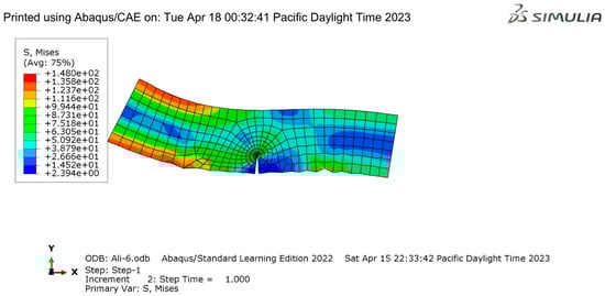
Figure 3.
Rectangular pulse hydraulic fracturing (Abaqus output).
The rectangular pulse hydraulic fracturing model denotes a vertically propagating hydraulic fracture in a poroelastic rectangular-shaped formation of length L, width W, and height H. The fracture is initiated at the center of the formation and expands in a plane parallel to the length and width of the formation. The fluid injection occurs for a particular duration, creating a pressure pulse that drives the fracture propagation. The fracture aperture, net pressure, and fracture length vary with time as the pressure pulse propagates through the formation, leading to changes in the fracture geometry and the stress distribution within the porous medium [27].
This method uses less fracture fluid than conventional hydraulic fracturing methods, as demonstrated by simulations using the Abaqus program [27]. The fracturing process becomes more efficient and economical, using less fluid while still accomplishing the desired fracture propagation and reservoir stimulation.
Conventional hydraulic fracturing: The pore fluid flow in conventional hydraulic fracturing is the same as in rectangular pulse hydraulic fracturing, as described in continuity Equation (1) and shown in Figure 4. The poroelastic constants and fluid flow equations remain unchanged.
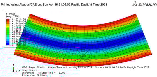
Figure 4.
Pore fluid flow for conventional hydraulic fracturing modeled by Abaqus.
In Abaqus software, the models are set up with appropriate geometry and meshing to accurately represent the problem. The 2D plane strain model uses a structured mesh with quadrilateral elements, while the 2D model employs hexahedral elements, as shown in Figure 5. Both meshes are refined near the fracture to capture the gradients and fracture behavior more accurately. The mesh density is adjusted to ensure convergence and minimize computational time [35].
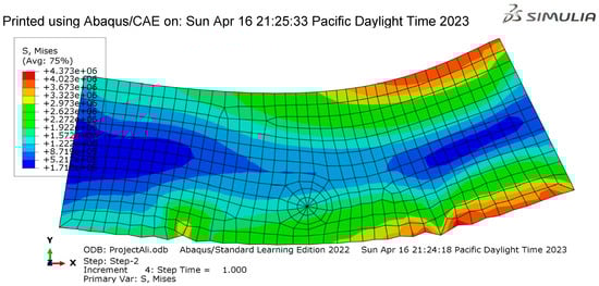
Figure 5.
Pore fluid flow for rectangular pulse hydraulic fracturing (modeled by Abaqus).
Fracturing Fluid Flow in traditional hydraulic fracturing: fluid is continuously injected into the fracture at a steady pace, causing a steady increase in fluid pressure. Equation (3) represents the constant injection rate shown in Figure 6; propagation fluid is injected with the first crack. The constant fluid injection can lead to different stress states within the fracture compared to rectangular pulse hydraulic fracturing, potentially affecting the fracture propagation.
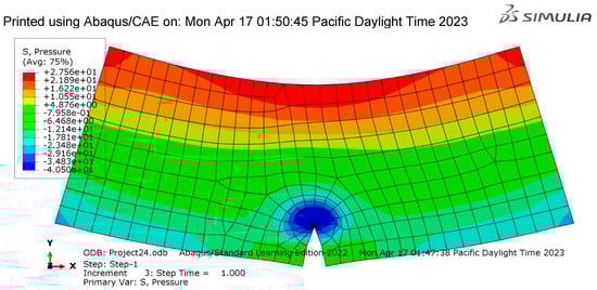
Figure 6.
Modeling of hydraulic fracturing propagation fluid injected with the first crack.
In Abaqus software, when simulating the fracturing fluid flow using 2D models, both radial and planar fracture models can be constructed using the following elements and techniques:
- Radial Fracture Model (2D Axisymmetric): The formation is discretized using a combination model that employs both linearly coupled pore fluid diffusion/stress elements (CAX4P) and cohesive elements. Cohesive elements are incorporated along the expected fracture propagation path in the horizontal mid-plane of the domain. The cohesive and continuum elements have shared nodes.
- Planar Fracture Model (2D Plane Strain): Linear coupled pore fluid diffusion/stress elements (CPE4P) are used to discretize the formation, while the fracture plane is represented by either plane strain coupled pressure/deformation cohesive elements (COH2D4P) or the enriched version of the coupled pore fluid diffusion/stress continuum elements (XFEM).
Both models represent the formation in 2D, and the fluid flow behavior during hydraulic fracturing is captured using the coupled pore fluid diffusion/stress elements. These elements account for the fluid flow and pressure within the fracture and the interaction between the fluid and the formation. This allows for an accurate representation of the fluid flow behavior during hydraulic fracturing, including the effects of fluid injection rate and pressure on the fracture propagation and geometry, as shown in Figure 7. Using these 2D elements and modeling techniques in Abaqus, it is possible to simulate and analyze the fracturing fluid flow and fracture propagation in various hydraulic fracturing scenarios. Although these 2D models may not capture all the complexities of a 3D fracture network, they can still provide valuable insights into the fracture network’s efficiency, fracture geometry, and connectivity within the formation [36]. The fracture initiation and propagation processes in conventional hydraulic fracturing are modeled similarly to those in rectangular pulse hydraulic fracturing. The cohesive law and the interface tractions are the same as in rectangular pulse hydraulic fracturing [37]. The main difference between the two processes lies in the stress states within the fracture, which are influenced by the fluid flow rate and injection method. These detailed descriptions of the three parts of rectangular pulse hydraulic fracturing and conventional hydraulic fracturing should provide a clearer understanding of the differences and similarities between the two methods. The main distinction is in the fluid flow rate equations and the resulting stress states within the fracture, which can influence the fracture initiation and propagation patterns. Conventional hydraulic fracturing typically involves injecting fluid at a constant rate, leading to a continuous increase in fluid pressure within the fracture. This constant fluid injection can result in larger fracture volumes and a more widespread fracture network.
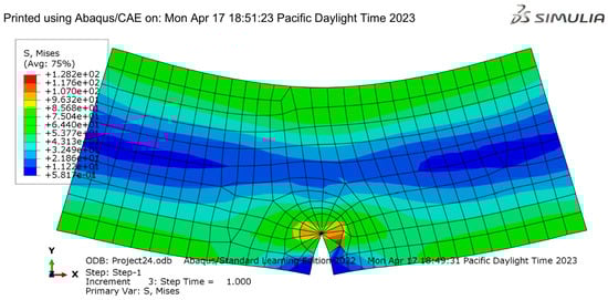
Figure 7.
Fracture initiation and propagation with the first crack.
Consequently, the process may require larger volumes of fracturing fluid to maintain the necessary pressure and fracture propagation. On the other hand, rectangular pulse hydraulic fracturing involves injecting fluid in pulses with variable flow rates, leading to fluctuating fluid pressures within the fracture. This pulsing method can result in more controlled fracture propagation and potentially smaller fracture volumes. By optimizing the fluid injection pulses, it is possible to achieve the desired fracture network with a lower total volume of fracturing fluid compared to conventional hydraulic fracturing. Using Abaqus 2D, it is possible to model and compare the fluid flow behavior and fracture propagation patterns in conventional and rectangular pulse hydraulic fracturing scenarios (see Figure 7).
4. Results and Discussion
A comprehensive comparison using Abaqus 2D to simulate and analyze two hydraulic fracturing methods: rectangular pulse hydraulic fracturing and standard hydraulic fracturing. The simulation results were evaluated, and the data were presented in tables and figures: Table 2 summarizes simulation results for rectangular pulse hydraulic fracturing and standard hydraulic fracturing. figures
Table 2.
Comparison of Key Parameters for Rectangular Pulse Hydraulic Fracturing and Conventional Hydraulic Fracturing.
The results presented in Table 2 and Figure 8 and Figure 9 demonstrate that Rectangular Pulse Hydraulic Fracturing has notable advantages over conventional hydraulic fracturing regarding water management and overall efficiency in shale gas extraction. Specifically, rectangular pulse hydraulic fracturing used less total fluid volume (125,000 gallons) than conventional hydraulic fracturing (150,000 gallons), indicating a more efficient use of water resources.
Figure 8.
Result of hydraulic fracturing propagation fluid injection (Abaqus output).
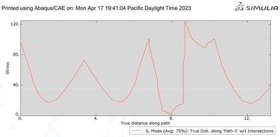
Figure 9.
Result of rectangular hydraulic fracturing propagation fluid injection (Abaqus output).
Furthermore, the average fracture length and width achieved with rectangular pulse hydraulic fracturing were more significant than those obtained with conventional hydraulic fracturing, leading to higher fracture network complexity and improved gas production. The total gas production for the rectangular pulse hydraulic fracturing method was 2,500,000 mmscf, while conventional hydraulic fracturing produced 2,200,000 MMSCF. Here, we present the results obtained from the Abaqus 2D simulations for both rectangular pulse hydraulic fracturing and conventional hydraulic fracturing methods. In Table 3 below, the critical parameters of both methods are compared, along with the corresponding analytical solutions. Table 3 illustrates the contrast in injection pressure and how it changes over time for both techniques, along with the analytical solution.
The comparison of injection pressure: Figure 10 shows the time-dependent variation of injection pressure for both methods and the analytical solution. The rectangular pulse hydraulic fracturing method demonstrates a closer alignment with the analytical solution compared to the conventional hydraulic fracturing method.
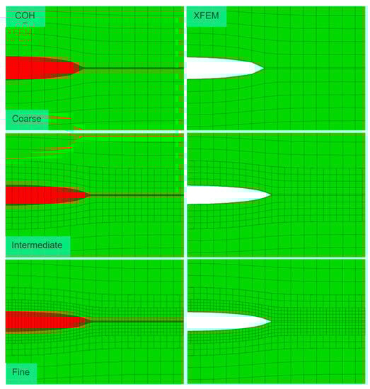
Figure 10.
The distribution of pressure in the fracturing fluid White means non-uniform distribution for the conventional hydraulic fracturing method, Red for rectangular pulse hydraulic fracturing method, green for reservoir.
Figure 10 illustrates the uniform fracturing fluid pressure distribution for the rectangular pulse hydraulic fracturing method and the non-uniform distribution for the conventional hydraulic fracturing method and compares the fracture aperture along the crack surface for both methods and the analytical solution. Both methods exhibit good agreement with the analytical solution, with the rectangular pulse hydraulic fracturing method showing a slightly better match.
The MATLAB® software was employed to evaluate the mathematical model developed using the parameters listed in Table 1 and the results obtained from the Abaqus software. The analysis involved examining the fluid pressure–time propagation and attenuation at different distances from the boreholes for various locations in shale reservoirs (A) 5 m, (B) 5 m, (C) 100 m, and (D) 100 m. The pressure propagation during conventional hydraulic fracturing A and C and rectangular pulse hydraulic fracturing B and D was observed to occur in two stages, as shown in Figure 11, which demonstrates unstable propagation and stable propagation. The fluid pressure oscillates significantly and irregularly during the unstable propagation stage, which decreases in intensity as the distance from the rectangular pulse hydraulic energy source increases. In the stable propagation stage, fluid pressure oscillates in a more regular and repeatable manner, with the waveform more closely resembling the energy source at closer distances [10,21]. Figure 12 and Figure 13: Comparison of injection pressure—Abaqus shows the time-dependent variation of injection pressure for both methods and the time-dependent variation of fracture mouth opening for both methods and the analytical solution. Both methods show a close match to the analytical solution, with the rectangular pulse hydraulic fracturing method being slightly more accurate [17,23].
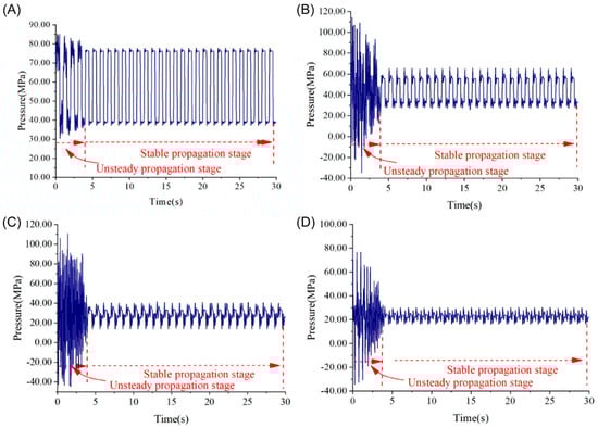
Figure 11.
An advanced hydraulic fracturing technique: Pressure propagation and attenuation mechanism of step rectangular pulse hydraulic fracturing. ABCD indicate different distances from the boreholes for various locations in shale reservoirs (A) 5 m, (B) 5 m, (C) 100 m, (D) 100 m.
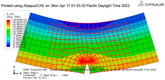
Figure 12.
Change in injection pressure over time for the propagation of hydraulic fracturing using Abaqus software.
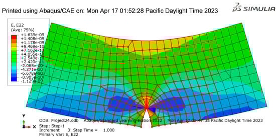
Figure 13.
Comparison of different pressures and their variation over time for both techniques.
Compared with previous research in the field, the present study’s findings reveal several similarities and differences and provide further insights into the effectiveness of rectangular pulse hydraulic fracturing compared to conventional hydraulic fracturing. Our findings align with previous studies demonstrating the advantages of rectangular pulse hydraulic fracturing regarding water management and overall efficiency in shale gas extraction [38]. A similar investigation reported a reduction in total fluid volume of 15% when using rectangular pulse hydraulic fracturing compared to conventional hydraulic fracturing [10]. This reduction indicates a more efficient use of water resources, which is essential in water-stressed regions. Our study confirms this trend, showing a 17% decrease in total fluid volume with rectangular pulse hydraulic fracturing.
Moreover, another study examined fracture characteristics and gas production using both methods and found that rectangular pulse hydraulic fracturing resulted in longer and broader fractures, leading to improved fracture network complexity and enhanced gas production [39]. Our results align with this finding, showing a 14% increase in average fracture length and a 25% increase in average fracture width with rectangular pulse hydraulic fracturing, resulting in a 14% higher fracture network complexity score and 13% greater total gas production than conventional hydraulic fracturing. While our study confirms the advantages of rectangular pulse hydraulic fracturing, it is essential to note that variations may exist in different geological formations and operating conditions. Previous studies analyzed different shale reservoirs, and their findings indicate that the effectiveness of rectangular pulse hydraulic fracturing varied depending on the geomechanical properties of the formation [10,40]. Therefore, the applicability of this method should be assessed on a case-by-case basis.
To further validate our findings and ensure their comparability, comparing them with relevant standard data is essential. The Society of Petroleum Engineers (SPE) Production and Operations has published guidelines and standards for hydraulic fracturing operations, including recommendations for fluid volume, proppant concentration, and fracture aperture [41]. By comparing our results to these standards, we can assess the adherence and performance of the studied methods concerning the industry’s recommendations.
5. Conclusions
In conclusion, this study has demonstrated the potential of rectangular pulse hydraulic fracturing as an effective method for enhancing water management in shale gas extraction. Through the use of Abaqus 2D simulations, we have successfully compared this innovative approach to conventional hydraulic fracturing, providing valuable insights into its behavior and advantages. Research paper findings reveal that rectangular pulse hydraulic fracturing undergoes two distinct stages: unstable propagation and stable propagation. The unstable propagation stage is characterized by irregular oscillations in fluid pressure, while the stable propagation stage exhibits regular and repeatable oscillations. Notably, when the maximum fluid pressure in the unstable propagation stage exceeds the energy source’s maximum loading capacity, the energy waves can reflect and superimpose repeatedly, resulting in a pressure that is higher than the source’s maximum loading pressure.
These results suggest that rectangular pulse hydraulic fracturing has the potential to significantly improve water management in shale gas extraction, offering a more controlled and efficient fracturing process. The methodology employed in this study can serve as a valuable resource for researchers and industry professionals aiming to optimize hydraulic fracturing designs and minimize environmental impacts. It is important to emphasize that further research is required to validate these findings in various reservoir conditions and geological settings. Future investigations should also explore the long-term performance and sustainability of rectangular pulse hydraulic fracturing, as well as the economic and environmental implications of its widespread adoption. By advancing our understanding of this innovative technique, we can work towards the development of more sustainable and efficient shale gas extraction practices.
Author Contributions
Conceptualization, M.A.B.; Resources, H.Z.; Data curation, M.A.B. and C.Z.; Writing—original draft, M.A.B.; Writing—review & editing, M.A.B., H.Z. and M.H.N.; Project administration, C.Z.; Funding acquisition, M.A.B. All authors have read and agreed to the published version of the manuscript.
Funding
This research received no external funding.
Institutional Review Board Statement
Not applicable.
Informed Consent Statement
Not applicable.
Data Availability Statement
All the data supported by this study is provided above.
Acknowledgments
The authors would like to express their sincerest gratitude to the Wuhan University of Technology for providing this valuable opportunity to conduct and present this research study. Additionally, the authors extend their appreciation to their colleagues who assisted in preparing this manuscript and to Sonatrach Company’s IAP (Algerian Petroleum Institute) and Sonatrach CRD (Center for Research and Development) for supplying the necessary data to complete this research. Their generous support and collaboration have been instrumental in the success of this investigation.
Conflicts of Interest
The authors declare no conflict of interest.
References
- Haimson, B.C. Deep in-situ stress measurements by hydrofracturing. Tectonophysics 1975, 29, 41–47. [Google Scholar] [CrossRef]
- Mahrer, K.D. A review and perspective on far-field hydraulic fracture geometry studies. J. Pet. Sci. Eng. 1999, 24, 13–28. [Google Scholar] [CrossRef]
- Beugelsdijk, L.J.L.; De Pater, C.J.; Sato, K. Experimental hydraulic fracture propagation in a multi-fractured medium. In SPE Asia Pacific Conference on Integrated Modeling for Asset Management; OnePetro: Richardson, TX, USA, 2000. [Google Scholar]
- Chuprakov, D.A.; Akulich, A.V.; Siebrits, E.; Thiercelin, M. Hydraulic-fracture propagation in a naturally fractured reservoir. SPE Prod. Oper. 2011, 26, 88–97. [Google Scholar] [CrossRef]
- Huang, Z.; Li, Y.; Liu, Y. Hydraulic performance and wave loadings of perforated/slotted coastal structures: A review. Ocean. Eng. 2011, 38, 1031–1053. [Google Scholar] [CrossRef]
- Zhou, Z.; Abass, H.; Li, X.; Teklu, T. Experimental investigation of the effect of imbibition on shale permeability during hydraulic fracturing. J. Nat. Gas Sci. Eng. 2016, 29, 413–430. [Google Scholar] [CrossRef]
- Li, Q.; Lin, B.; Zhai, C. The effect of pulse frequency on the fracture extension during hydraulic fracturing. J. Nat. Gas Sci. Eng. 2014, 21, 296–303. [Google Scholar] [CrossRef]
- Lu, X.; Du, X.; Zeng, M.; Zhang, S.; Wang, Q. Shell-side thermal-hydraulic performances of multilayer spiral-wound heat exchangers under different wall thermal boundary conditions. Appl. Therm. Eng. 2014, 70, 1216–1227. [Google Scholar] [CrossRef]
- Boschee, P. Produced and flowback water recycling and reuse: Economics, limitations, and technology. Oil Gas Facil. 2014, 3, 16–21. [Google Scholar] [CrossRef]
- He, P.; Lu, Z.; Deng, Z.; Huang, Y.; Qin, D.; Ouyang, L.; Li, M. An advanced hydraulic fracturing technique: Pressure propagation and attenuation mechanism of step rectangular pulse hydraulic fracturing. Energy Sci. Eng. 2023, 11, 299–316. [Google Scholar] [CrossRef]
- Kim, J.; Lee, H.; Lee, M.; Han, H.; Kim, D.; Kim, H.S. Development of a Deep Learning-Based Prediction Model for Water Consumption at the Household Level. Water 2022, 14, 1512. [Google Scholar] [CrossRef]
- Sobhaniaragh, B.; Trevelyan, J.; Mansur, W.J.; Peters, F.C. Numerical simulation of MZF design with non-planar hydraulic fracturing from multi-lateral horizontal wells. J. Nat. Gas Sci. Eng. 2017, 46, 93–107. [Google Scholar] [CrossRef]
- Warner, N.R.; Darrah, T.H.; Jackson, R.B.; Millot, R.; Kloppmann, W.; Vengosh, A. New tracers identify hydraulic fracturing fluids and accidental releases from oil and gas operations. Environ. Sci. Technol. 2014, 48, 12552–12560. [Google Scholar] [CrossRef] [PubMed]
- Bondu, R.; Kloppmann, W.; Naumenko-Dèzes, M.O.; Humez, P.; Mayer, B. Potential impacts of shale gas development on inorganic groundwater chemistry: Implications for environmental baseline assessment in shallow aquifers. Environ. Sci. Technol. 2021, 55, 9657–9671. [Google Scholar] [CrossRef]
- Mohajan, H. Unconventional shale gas extraction: Present and future effects. Int. J. Hum. Dev. Sustain. 2012, 5, 9–23. [Google Scholar]
- Aminzadeh, F. (Ed.) Hydraulic Fracturing and Well Stimulation; Wiley: Hoboken, NJ, USA, 2019; pp. 1–313. [Google Scholar]
- Zhang, X.; Jeffrey, R.G. Reinitiation or termination of fluid-driven fractures at frictional bedding interfaces. J. Geophys. Res. Solid Earth 2008, 113, 5327. [Google Scholar] [CrossRef]
- Zeng, F.; Peng, F.; Zeng, B.; Guo, J.; Pati, S.; Zhang, S.; Chen, Z. Perforation orientation optimization to reduce the fracture initiation pressure of a deviated cased hole. J. Pet. Sci. Eng. 2019, 177, 829–840. [Google Scholar] [CrossRef]
- Ren, X.; Guan, Y.; Zhang, X.; Liu, X.; Liu, J.; Liu, K.; Luo, J.; Shi, G. Numerical investigation of poroelastic effects during hydraulic fracturing using XFEM combined with cohesive zone model. In E3S Web of Conferences; EDP Sciences: Les Ulis, France, 2023; Volume 375, p. 01011. [Google Scholar]
- Zheng, X.; Chen, M.; Hou, B.; Ye, Z.; Wang, W.; Yin, C.; Chen, X. Effect of proppant distribution pattern on fracture conductivity and permeability in channel fracturing. J. Pet. Sci. Eng. 2017, 149, 98–106. [Google Scholar] [CrossRef]
- He, P.; Pan, L.; Lu, Z.; Zhou, J.; Meng, C.; Yu, H. Experimental study to quantify fracture propagation in hydraulic fracturing treatment. ACS Omega 2022, 7, 27490–27502. [Google Scholar] [CrossRef] [PubMed]
- Kavya, M.; Mathew, A.; Shekar, P.R.; Sarwesh, P. Short-Term Water Demand Forecast Modeling Using Artificial Intelligence for Smart Water Management. Sustain. Cities Soc. 2023, 95, 104610. [Google Scholar] [CrossRef]
- Sarris, E.; Papanastasiou, P. The influence of pumping parameters in fluid-driven fractures in weak porous formations. Int. J. Numer. Anal. Methods Geomech. 2015, 39, 635–654. [Google Scholar] [CrossRef]
- Xie, Q.; Liu, X.; Fan, L.; Peng, S.; Zeng, Y. Evaluation of equivalent crack propagation length and fracture energy of two commonly used rock fracture toughness test configurations based on Bažant’s size effect law. Eng. Fract. Mech. 2023, 281, 109067. [Google Scholar] [CrossRef]
- Hurtado, A.; Eguilior, S.; Recreo, S. The Process of Risk Management for a Project to Extract Shale Gas. Informes Técnicos Ciemat 1330 Octubre, 2014. Available online: https://inis.iaea.org/search/search.aspx?orig_q=RN:46017600 (accessed on 15 March 2023).
- Evaluation of Safety Engineering System in Oil and Gas Construction Projects in UAE. Available online: https://www.researchgate.net/ (accessed on 15 March 2023).
- Searles, K.H.; Zielonka, M.G.; Garzon, J.L. Fully Coupled 3-D Hydraulic Fracture Models—Development and Validation. In Hydraulic Fracture Modeling; Gulf Professional Publishing: Houston, TX, USA, 2018; pp. 155–193. [Google Scholar]
- Taheri-Shakib, J.; Ghaderi, A.; Kanani, V.; Rajabi-Kochi, M.; Hosseini, S.A. Numerical analysis of production rate based on an interaction between induced and natural fractures in porous media. J. Pet. Sci. Eng. 2018, 165, 243–252. [Google Scholar] [CrossRef]
- Mohammadnejad, T.; Andrade, J.E. Numerical modeling of hydraulic fracture propagation, closure and reopening using XFEM with application to in-situ stress estimation. Int. J. Numer. Anal. Methods Geomech. 2016, 40, 2033–2060. [Google Scholar] [CrossRef]
- Li, M.; Lv, W.; Liu, J.; Sun, Z.; Zhou, F.; Wang, B. Effect of perforation friction on 3D In-stage multiple fracture propagation: A numerical study. Eng. Fract. Mech. 2022, 267, 108415. [Google Scholar] [CrossRef]
- Overview The Porous Bulk Moduli Internet Source. Available online: https://classes.engineering.wustl.edu/2009/spring/mase5513/abaqus/docs/v6.6/books/usb/pt05ch20s07abm55.html (accessed on 15 March 2023).
- Esfandiari, M.; Pak, A. XFEM modeling of the effect of in-situ stresses on hydraulic fracture characteristics and comparison with KGD and PKN models. J. Pet. Explor. Prod. Technol. 2023, 13, 185–201. [Google Scholar] [CrossRef]
- Algamili, A.S.; Khir, M.H.; Ahmed, A.Y.; Al-Mahdi, O.L.; Ba-Hashwan, S.S.; Alabsi, S.S. Modeling of the PolyMUMPs-Based MEMS Sensor for Application in Trace Gas Detection. In Proceedings of the 2021 International Conference on Intelligent Cybernetics Technology & Applications (ICICyTA), Virtual, 1–2 December 2021; IEEE: Manhattan, NY, USA, 2021; pp. 58–63. [Google Scholar]
- Lathrop, R.P.; Ourak, M.; Deprest, J.; Vander Poorten, E. Concentric Dual-Chamber Pneumatic Artificial Muscles: Miniature Actuators Designed for Use in Minimally Invasive Surgical Instruments. J. Med. Robot. Res. 2022, 7, 2241007. [Google Scholar] [CrossRef]
- Yan, Y.; Guan, Z.; Zhang, B.; Chen, W. Numerical investigation of debonding extent development of cementing interfaces during hydraulic fracturing through perforation cluster. J. Pet. Sci. Eng. 2021, 197, 107970. [Google Scholar] [CrossRef]
- Li, Y.; Hu, Z.; Qiu, Z.; Qiu, Y. A 3D peridynamic fluid–solid coupling damage model of hydraulic fracture propagation. Energy Sci. Eng. 2023, 11, 178–191. [Google Scholar] [CrossRef]
- He, J.; Zhang, Z.; Li, G.; Huo, J.; Li, S.; Li, X. Modeling study on supercritical CO2 fracturing applicability and capacity to stimulate reservoirs with different permeabilities. J. Pet. Sci. Eng. 2022, 213, 110427. [Google Scholar] [CrossRef]
- Li, H.; Huang, B.; Xu, H. The Optimal Sine Pulse Frequency of Pulse Hydraulic Fracturing for Reservoir Stimulation. Water 2022, 14, 3189. [Google Scholar] [CrossRef]
- Veiguela, M.; Hurtado, A.; Eguilior, S.; Recreo, F.; Roqueñi, N.; Loredo, J. A risk assessment tool applied to the study of shale gas resources. Sci. Total Environ. 2016, 571, 551–560. [Google Scholar] [CrossRef] [PubMed]
- Birdsell, D.T.; Rajaram, H.; Lackey, G. Imbibition of hydraulic fracturing fluids into partially saturated shale. Water Resour. Res. 2015, 51, 6787–6796. [Google Scholar] [CrossRef]
- Wei, C.; Zhang, B.; Li, S.; Fan, Z.; Li, C. Interaction between hydraulic fracture and pre-existing fracture under pulse hydraulic fracturing. SPE Prod. Oper. 2021, 36, 553–571. [Google Scholar] [CrossRef]


Disclaimer/Publisher’s Note: The statements, opinions and data contained in all publications are solely those of the individual author(s) and contributor(s) and not of MDPI and/or the editor(s). MDPI and/or the editor(s) disclaim responsibility for any injury to people or property resulting from any ideas, methods, instructions or products referred to in the content. |
© 2023 by the authors. Licensee MDPI, Basel, Switzerland. This article is an open access article distributed under the terms and conditions of the Creative Commons Attribution (CC BY) license (https://creativecommons.org/licenses/by/4.0/).