Abstract
As an energy-efficient and low-carbon technology, ground-source heat pumps are promising to contribute to carbon neutrality in the building sector. A crucial component of these systems is the ground heat exchanger, which has been extensively studied through sandbox experiments. These experiments play a vital role in understanding heat transfer characteristics and validating simulation results. In order to facilitate the improvement of ground heat exchangers and the development of ground-source heat-pump systems, this article provides a comprehensive summary of existing sandbox experiments. The borehole sandbox experiments are classified into the single borehole experiment, borehole group experiment, seepage experiment, and multi-layer soil experiment. It was observed that the heat transfer efficiency of a single spiral tube is only 80% compared to that of a double spiral tube. Moving on to energy-pile sandbox experiments, they are further divided into mechanical performance, thermal performance, and thermal-mechanical coupled performance tests. It was revealed that the heat transfer distance of a single U-shaped energy pile in the radial direction is three times greater than in the vertical direction. For the mentioned sandbox experiments, the sandbox design, experiment conduction, testing conditions, and result analyses are summarized. To improve the sandbox experiments, there are still some difficulties in building a similarity experiment, testing the temperatures in a small error, controlling the boundary conditions accurately, and testing the thermophysical properties of soil accurately. Furthermore, the perspectives of sandbox experiments of ground heat exchangers are also proposed. The sandbox experiments under complex environment conditions or with novel composite energy geo-structures or ground heat exchangers with new materials and new technologies would be further investigated. By addressing these aspects, this review aims to provide guidelines for the design, construction, operation, and optimization of sandbox experiments for different ground heat exchangers, ultimately promoting the wider adoption of ground-source heat pumps in achieving carbon neutrality.
1. Introduction
Building energy consumption typically accounts for approximately 20–40% of the total energy consumption in different regions, with space heating and cooling alone contributing to over 40% of this consumption [1,2,3]. As a result, reducing energy consumption in air conditioning systems is of utmost importance for improving building energy efficiency and mitigating emissions [4,5,6]. With the improvement in living standards, the demand for indoor thermal comfort has significantly increased [7,8]. Therefore, it is crucial to develop and implement efficient air-conditioning technologies that can simultaneously maintain low building energy consumption and enhance indoor thermal conditions [9,10].
Ground-source heat pumps (GSHPs) [11,12,13,14] utilize the shallow ground as a low-grade heat source (or a heat sink) for heating (or cooling). During the winter, the heat pump unit absorbs low-grade heat from the soil to provide space heating for buildings. In the summer, the heat within the building is transferred to the soil through the system, cooling the building and storing the heat for subsequent use during the winter [15,16,17]. The soil temperature remains relatively stable throughout the year, making it an advantageous heat source [18,19,20]. This stability allows GSHPs to achieve a high heating coefficient of performance (COP) during winter and a high cooling COP during summer, highlighting their significant energy-saving potential [21,22,23].
In a GSHP system, the ground heat exchanger (GHE) is any critical component that exchanges heat with the soil [24,25,26]. The heat transfer performance of GHE affects the design and operation of the system [27,28]. Commonly used forms of GHEs include vertical boreholes [29,30,31] and energy piles [32,33,34,35]. Despite the energy efficiency of GSHP systems, some practical projects have experienced underperformance primarily due to suboptimal GHE designs [36]. With transient heat transfer or coupled heat/mass transfer processes in long-term operation, an accurate GHE model plays a key role in improving the GSHP system design. The heat transfer mechanism of GHEs can be investigated by two methods: simulation (e.g., numerical simulation [37,38] by using two model order reduction (MOR) methods [39], COMSOL environment [40], FORTRAN language [41] and analytical calculation [42,43] by considering thermophysical parameters and temperature distribution [44], non-uniformity of the ground [45], and temperature response [46]) and experiment (e.g., sandbox experiment [47,48,49,50] field test about energy piles [51,52,53] under groundwater flow [54], equipped with steel pipe heat exchangers [55]). Among these methods, the simulation is relatively easily performed under different working conditions, but it has errors caused by calculation assumptions. In addition, although the field test can reflect the practical behaviors of GHEs during operation, the cost is high, and there are many uncontrollable factors. In contrast to the field test, the parameters of the sandbox experiment are controllable and repeatable. Therefore, it provides a convenient and effective verification approach for simulation methods and also reveals the heat transfer mechanism of GHEs experimentally.
Numerous researchers have conducted sandbox experiments for different forms of GHEs to reveal the heat transfer mechanisms and validate the heat transfer models. According to the types of GHEs, sandbox experiments include borehole sandbox experiments [47,48,49,50] and energy pile sandbox experiments [56,57,58], considering various factors including conventional single borehole [47], circulating water flow in tubes [48], tube group thermal disturbance [59], underground seepage [60], and layered soil [61], etc. For the sandbox experiments [62] that do not use the similarity principle, the measurements can be utilized to verify the heat transfer mechanisms of GHEs under specific assumptions. As for the sandbox experiments following the similarity principle [63,64], the results can be directly referred to by the full-scale GHEs. The sandbox experiment tests the heat transfer mechanism of GHEs and provides an important experimental basis for the heat transfer model establishment. With increasing studies on diversified types of GHEs serving various GSHP systems, a comprehensive overview of GHE sandbox experiments is of great necessity to facilitate theoretical investigations as well as promote practical applications.
This paper presents an overview of GHE sandbox experiments by discussing the sandbox design, experimental procedures, and test results of both borehole and energy pile experiments. The research status of GHE sandbox experiments is also summarized to provide valuable insights into the current state of the field. Regarding borehole sandbox experiments, the focus lies on various aspects such as single borehole experiments, borehole group experiments, seepage experiments, and experiments considering multi-layered boreholes under complex geological conditions. In the case of energy pile sandbox experiments, the research primarily focuses on mechanical performance, thermal performance, and coupled thermal-mechanical performance experiments. By providing guidelines for the design, construction, operation, and optimization of sandbox experiments for different GHEs, this paper offers valuable insights for researchers and practitioners. The ultimate goal is to promote the development of reasonable GHE designs and facilitate wider adoption of ground source heat pump (GSHP) technology, thereby contributing to the pursuit of carbon neutrality and sustainable energy solutions.
2. Borehole Sandbox Experiment
The buried borehole sandbox experiment typically consists of scaled boreholes, a sandbox, soil, the seepage system, and a temperature testing system. As for the boundary conditions, the sandbox wall can be isothermal, adiabatic, or adiabatic-isothermal (adiabatic walls and bottom but isothermal top). The adiabatic boundaries can be achieved by coating insulation materials. The isothermal boundaries can be achieved by maintaining a constant indoor air temperature. The sandboxes can have cuboid or cylindrical shapes, and the soil inside can be clay, sand, or layered soil. The scaled borehole is typically created using simplified heating wires to represent a group of boreholes or metal tubes with circulating water, effectively mimicking the actual heat transfer process within the boreholes (including heat convection in the tube, heat conduction in the tube wall, and heat transfer through the surrounding soil). The seepage systems can emulate the seepage in vertical or horizontal directions. Wang et al. [47], Diao et al. [48], Xu et al. [49], and Li et al. [50,65] carried out conventional sandbox experiments with a single borehole. Chen et al. [66], Aydan et al. [67], and Zhang et al. [59] performed sandbox experiments with multiple buried borehole groups. Liu et al. [60] performed a sandbox experiment with seepage. Wang et al. [61] conducted a sandbox experiment with multi-layered soil. The heat transfer performances of boreholes considering different borehole forms, seepage conditions, thermal interference inside the tube group, and different soil layers have been mainly studied. Next, we will categorically introduce some research conducted on the borehole sandbox experiment.
2.1. Single Borehole Experiment
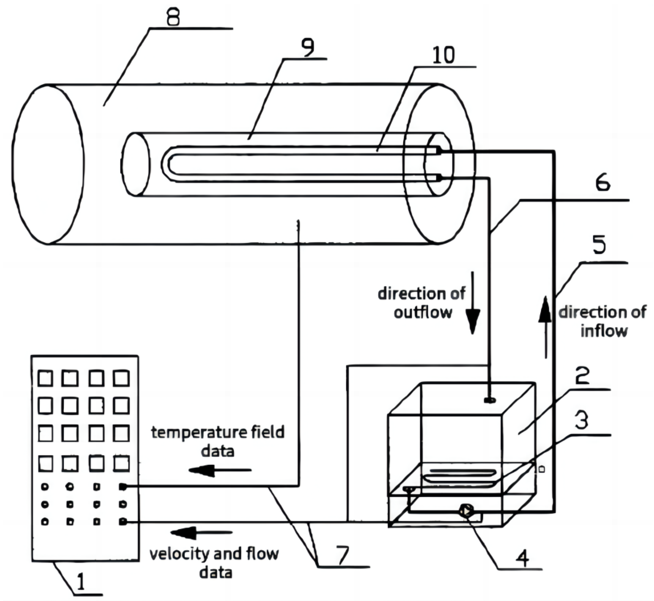
The single borehole sandbox experiment aims to reflect the heat transfer mechanism and validate the mathematical heat transfer model for an individual borehole. Some researchers [47,48,67,68] set up experiments based on the similarity principle and used the test results to reflect the heat transfer characteristics of a borehole in a practical project. The test rig built by Wang et al. [47] adopted a stainless-steel cylinder with a diameter of 0.8 m and a length of 5 m as a sandbox, as shown in Figure 1. The boundary condition is isothermal. In order to ensure the homogeneity of the soil within the sandbox, the entire cylinder is equipped with a rotary mechanism, enabling a 90° rotation from side to side. The U-shaped tube can be placed horizontally in the horizontal borehole to avoid the influence of the height difference between the inlet and outlet tubes. Two kinds of U-tubes (D32 and D25, nominal wall thickness of 3 mm) are adopted for comparison. In addition, the cylinder is separated into three sections by stainless steel plates along the axial direction to emulate the effects of different soil types and moisture contents at different depths on the heat transfer performance.
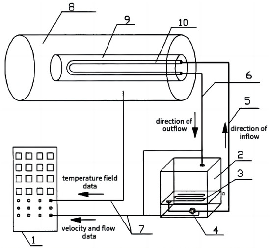
Figure 1.
Schematic diagram of a cylindrical borehole sandbox experiment [47]. 1. Control panel 2. Water tank 3. Electric heater 4. Water pump 5. Inlet tube 6. Outlet tube 7. Cable 8. Soil 9. Backfill 10. U-shaped tube.
Wang et al. [47] obtained reasonable boundary conditions of the U-tube heat exchanger for numerical simulation through experimental results. Moreover, they conducted simulations to evaluate the heat transfer characteristics of vertical double-helix tubes and investigated the effects of tube pitch, inlet velocity, and inlet temperature on the heat transfer performance. For the U-tube, the single spiral tube, and double spiral tubes with different pitches, the temperature distributions, heat transfer efficiencies, and heat capacities were compared. The results showed that the heat transfer performance of the spiral tube was better than that of the single U-tube with the same drilling depth. Additionally, the heat transfer performance was improved with the increase in the spiral pitch. The total heat transfer of the single spiral tube could only reach 80% of that of the double spiral tube. The heat transfer performance could be enhanced when the tube spacing was increased, and the pitch of the double helix tube was reduced appropriately.
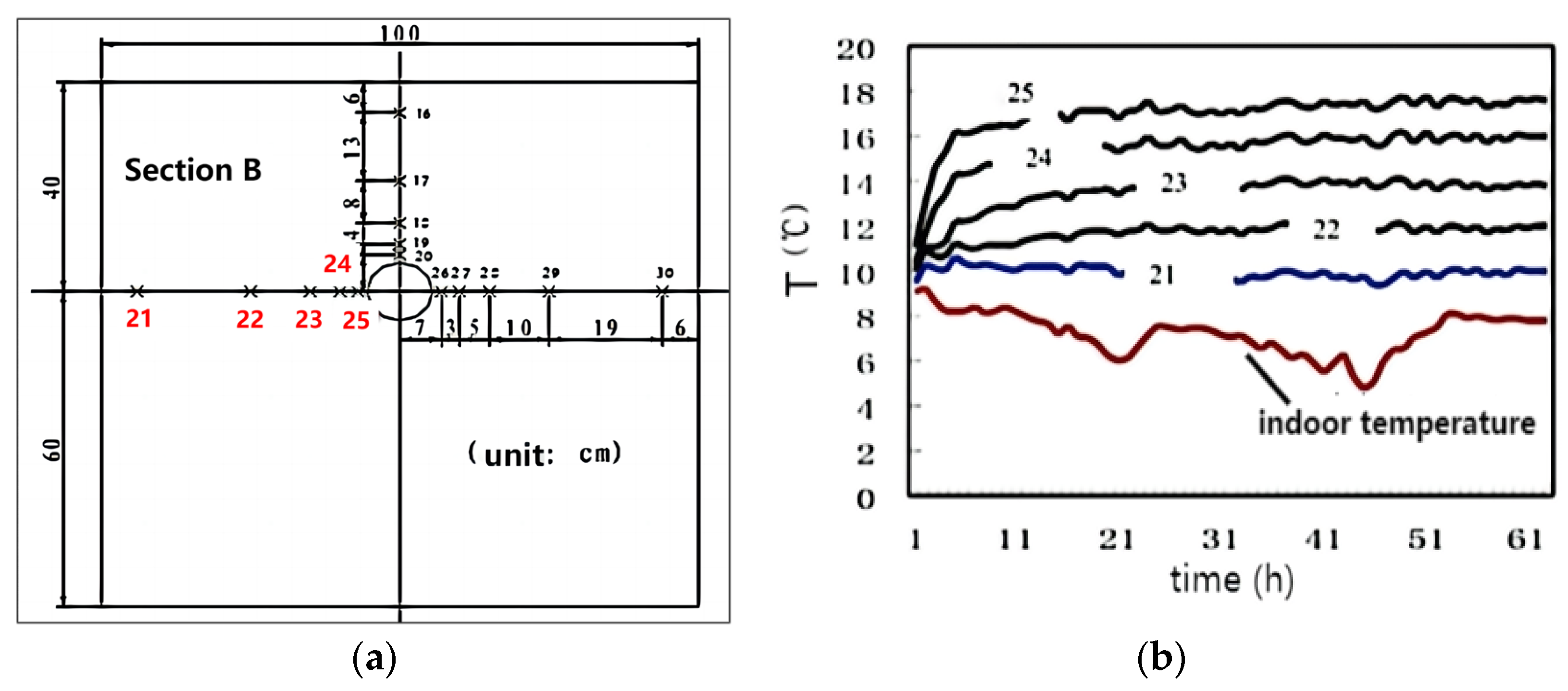
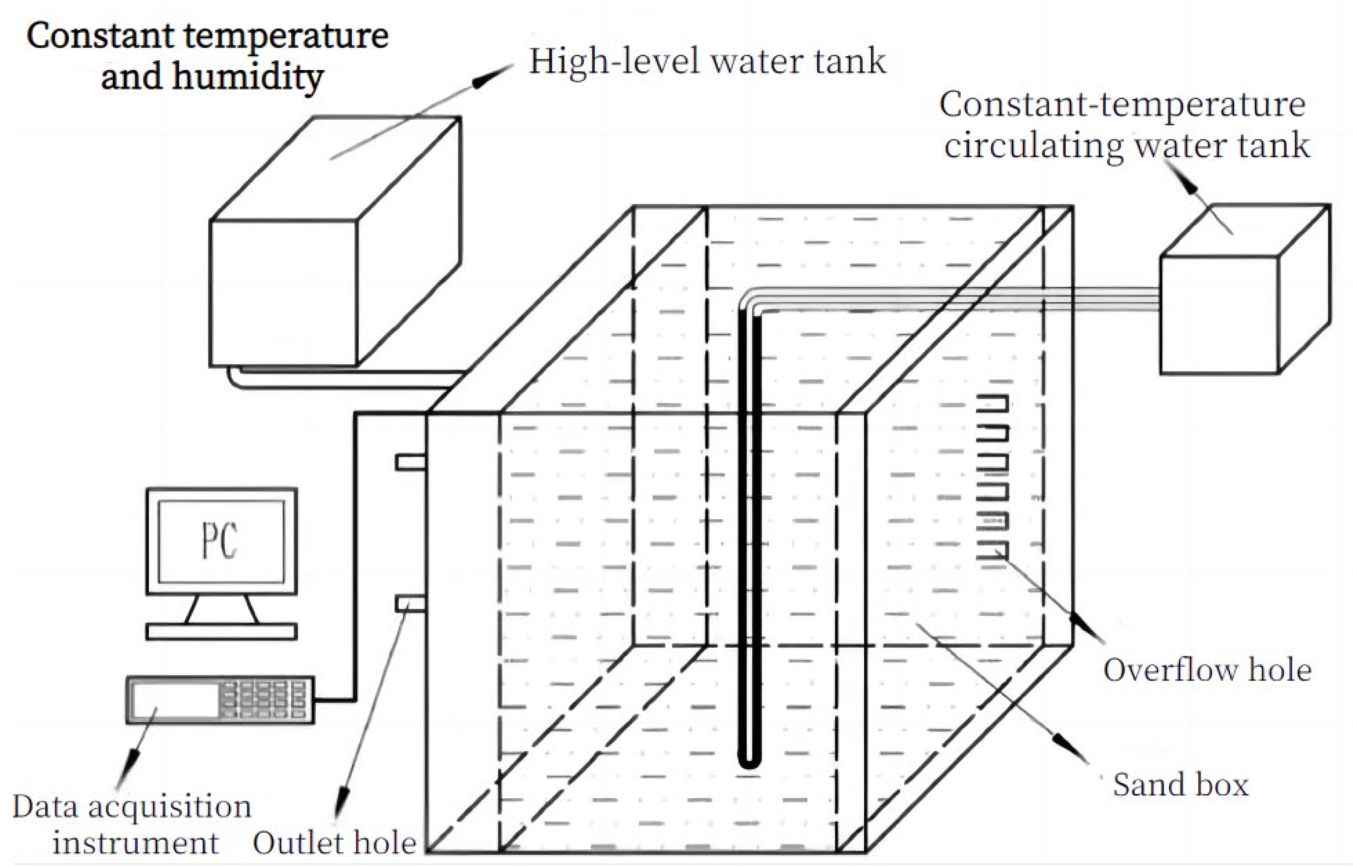
Different from the cylindrical experimental devices constructed by Wang et al. [47], experimental devices assembled by Diao et al. [48] used two cuboid sandboxes of 2 × 1.2 × 0.8 m and 4 × 1 × 1 m, as is shown in Figure 2. The sandbox was filled with fine dry sand and had isothermal boundary conditions. A U-tube was buried in the center of the box with circulating water flowing through it.

Figure 2.
Schematic diagram of a cuboid borehole sandbox experiment [48].
From the experiment of Diao et al. [48], it can be concluded that: Figure 3a shows the layouts of temperature measuring points in Section B. During operation, during the experiment, point 21 exhibited a consistently steady temperature, indicating that the boundary of the sandboxes remained unaffected by the heat transfer originating from the U-tube. As shown in Figure 3b, in the first few hours of operation under the inlet temperature of 20 °C, the soil temperatures near the U-tube (points 25, 24) rose rapidly, and the soil temperatures in other areas (e.g., points 23, 22, 21) had little increase. After a few hours, the temperature rises of all measuring points decreased, the temperature field tended to be stable, and the temperature gradient of soil close to the U-shaped tube was large.
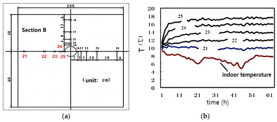
Figure 3.
Experimental results of a cuboid borehole sandbox [48]. (a) Temperature sensors in Section B. (b) Temperature curve in Section B.
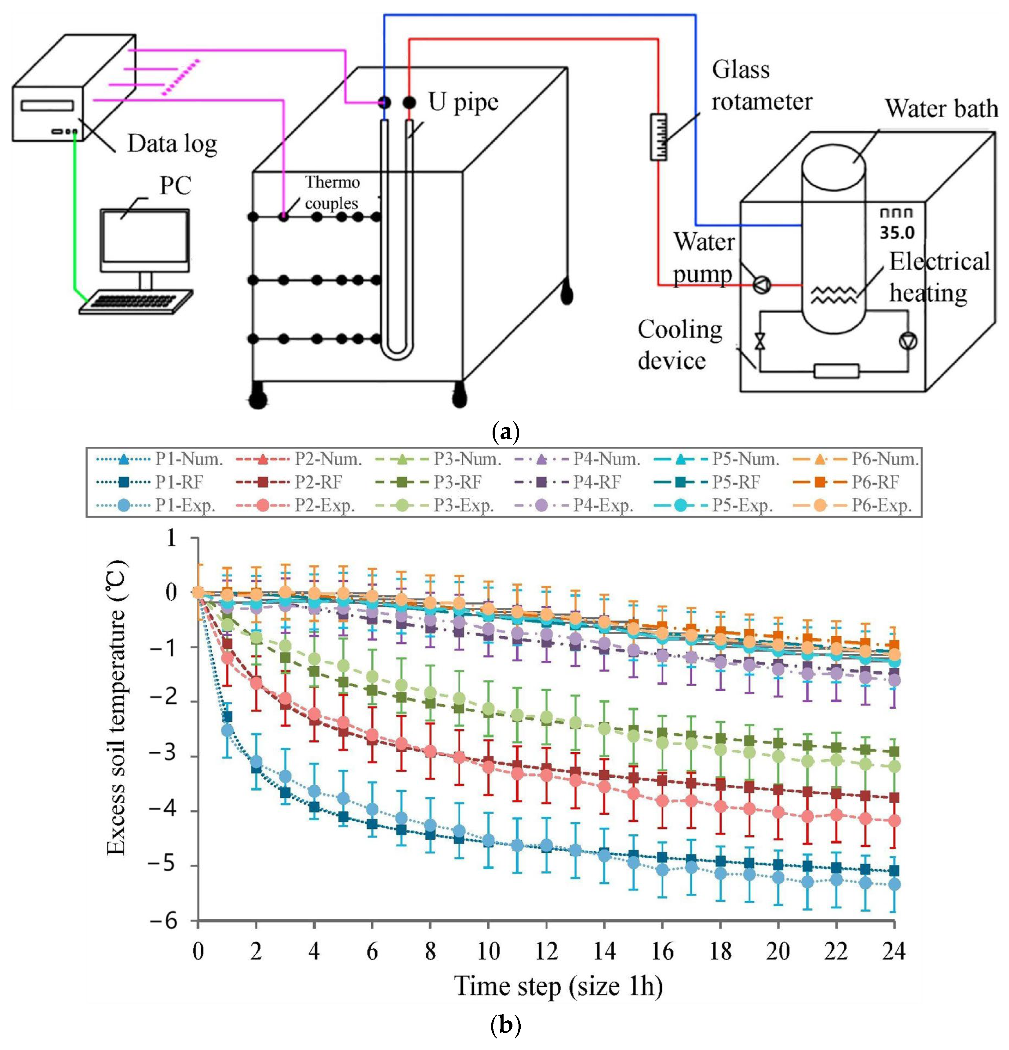
Different from the two experimental devices for horizontally placing a U-tube mentioned above, You et al. [62] developed a square sandbox device with a size of 1 × 1 × 1 m, as is shown in Figure 4a. The device was covered with insulation cotton to establish an adiabatic boundary condition, and a U-tube was centrally positioned within the sandbox. The U-tube had an inner diameter of 8 mm and a length of 950 mm. For measuring the water flow velocity within the U-shaped tube, a glass rotameter was used in the experiment. A water bath was employed to maintain a constant inlet water temperature, and six T-type thermocouples were used to test the soil temperature at typical locations to verify the mathematical model of the ground heat exchanger (GHE) proposed by the authors. When the excess temperature of inlet water temperature is −10 °C, the change of soil temperature at the typical points is shown in Figure 4b. Point 1, positioned on the outer wall of the heat exchange tube, displayed a decrease of 5.3 °C in soil temperature after 24 h. On the other hand, point 6, located 500 mm from the heat exchange tube, experienced a decline of only 0.5 °C in soil temperature during the same period.
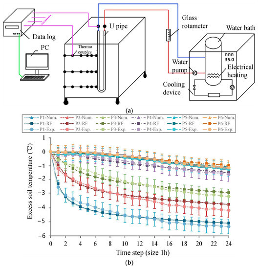
Figure 4.
A borehole sandbox experiment with a U-shaped tube and adiabatic boundaries [62]. (a) Schematic diagram of the sandbox experiment. (b) Typical soil temperatures.
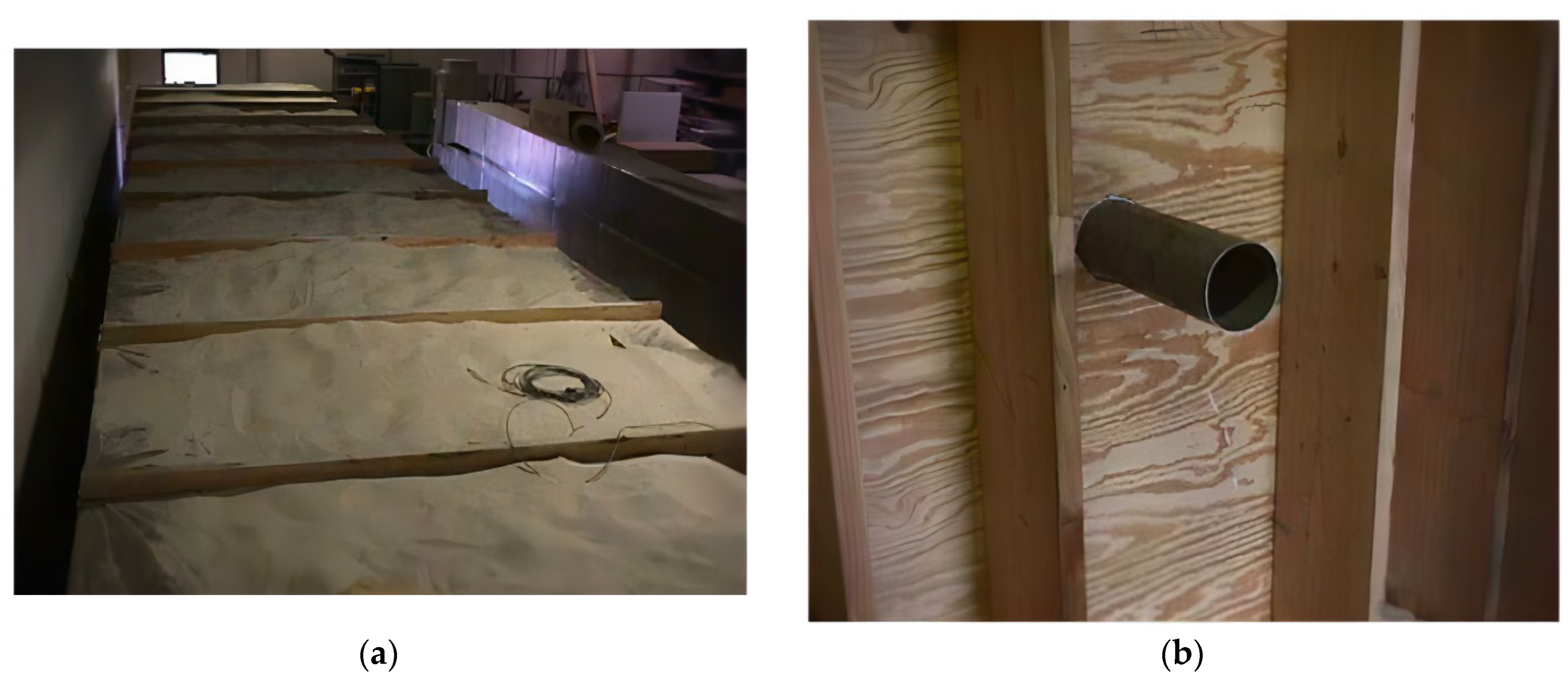
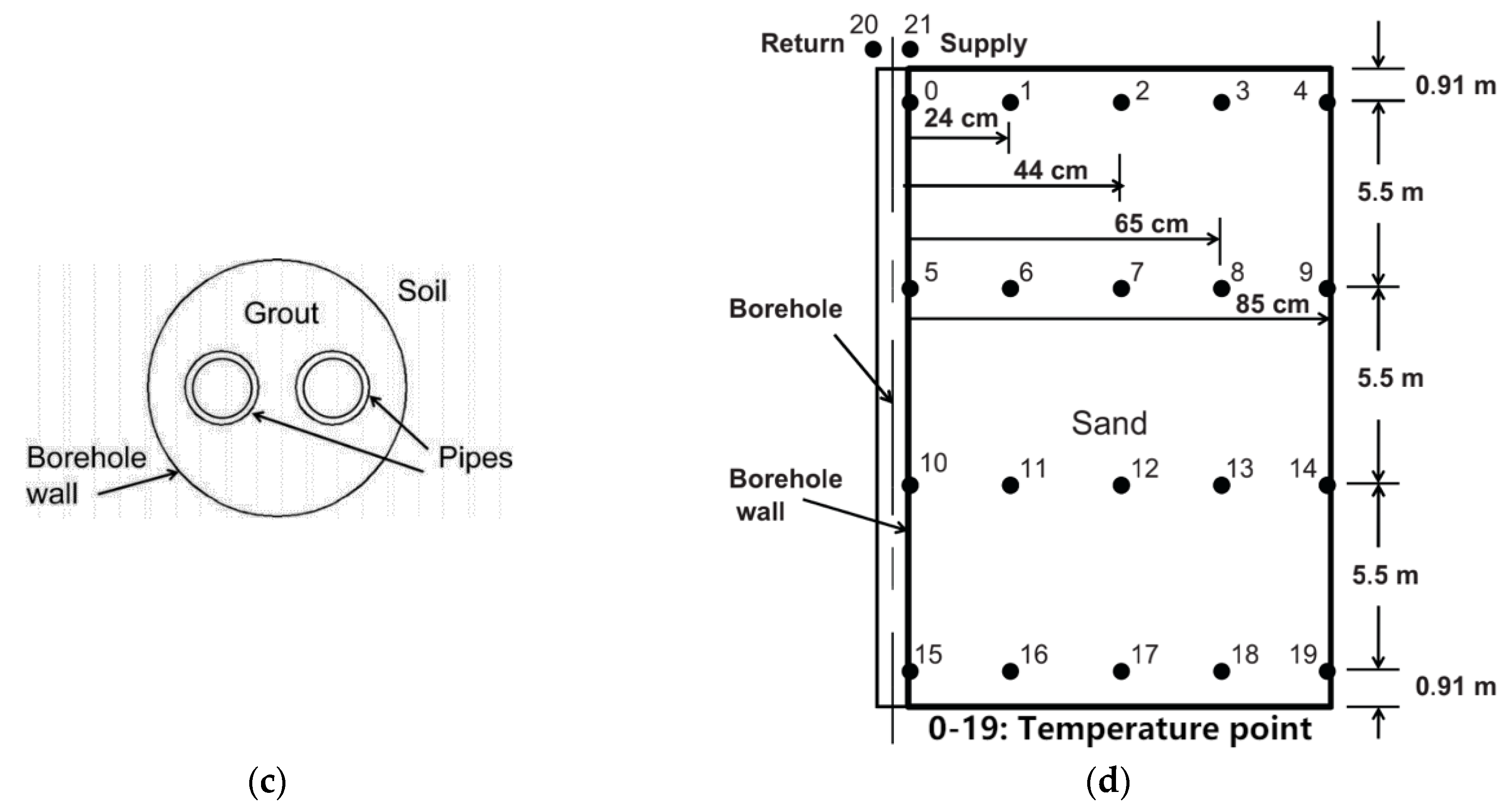
Beier et al. [69] used different materials to construct the experimental device and create an adiabatic boundary condition. Beier et al. [69] built a large wooden frame sandbox with a size of 18 × 1.8 × 1.8 m, which was lined with plastic and filled with saturated sand, as shown in Figure 5. The aluminum tube with an inner diameter of 12.6 cm was selected as a borehole, which had a length of 18 m and was located in the center of the sandbox. The U-shaped tube was made of high-density polyethylene (HDPE) with an outer diameter of 3.340 cm and an inner diameter of 2.733 cm. It was horizontally placed in the center of the borehole setup. The borehole was filled with cement slurry (20% solid, thermal conductivity 0.73 W/(m·K)) inside.
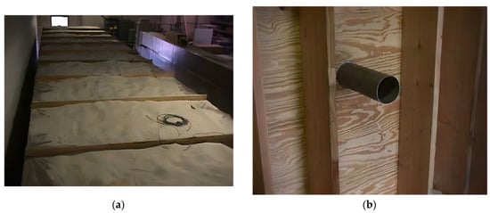
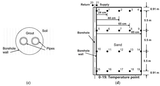
Figure 5.
A woody borehole sandbox experiment [69]. (a) Top view of the sandbox. (b) Side view of the sandbox. (c) Schematic diagram of tubes and borehole. (d) Temperature sensors in the sandbox.
The author conducted a thermal response test on the borehole, obtaining temperature measurements for the borehole wall and the soil at different distances (24 cm, 44 cm, 65 cm, and 85 cm) from the borehole wall, as shown in Figure 6. After approximately 0.7 h of testing, the temperature of the borehole wall began to rise steadily, exhibiting a linear increase after around 1.1 h. Roughly 7 h later, the soil temperature at a distance of 24 cm from the borehole wall started to rise, while the temperatures of the soil at 44 cm, 65 cm, and 85 cm from the borehole wall began to increase after 10 h. At the end of the test, the temperature rise at the sandbox wall (at 85 cm) was merely around 0.3 °C, indicating that the circulating water had little thermal effect on the sandbox boundary during the test. The temperatures of the borehole wall and the fluid increased at the same rate, and their temperature difference could reach 10 °C after about 10 h. This experiment provides detailed information regarding the working conditions, parameters, and results, enabling the validation of the mathematical model for borehole heat transfer.

Figure 6.
Experimental results of a woody borehole sandbox [69]. (a) Semi-logarithmic diagram of soil temperature at different distances. (b) Temperature differences between average fluid and borehole wall.
In the single borehole sandbox experiment, researchers commonly employ a scaled-down model that mimics an actual borehole. This model allows them to replicate the conditions of practical engineering projects in a laboratory setting by applying the principle of similarity. The experiment entails measuring the temperature distribution surrounding the borehole in various time intervals, with the aim of investigating the heat transfer characteristics.
The obtained experimental results serve to verify the precision and viability of the mathematical model. By meticulously analyzing and contrasting the experimental data, researchers can evaluate the extent to which the mathematical model is capable of accurately predicting the heat transfer behavior of boreholes in practical engineering projects.
2.2. Borehole Group Experiment
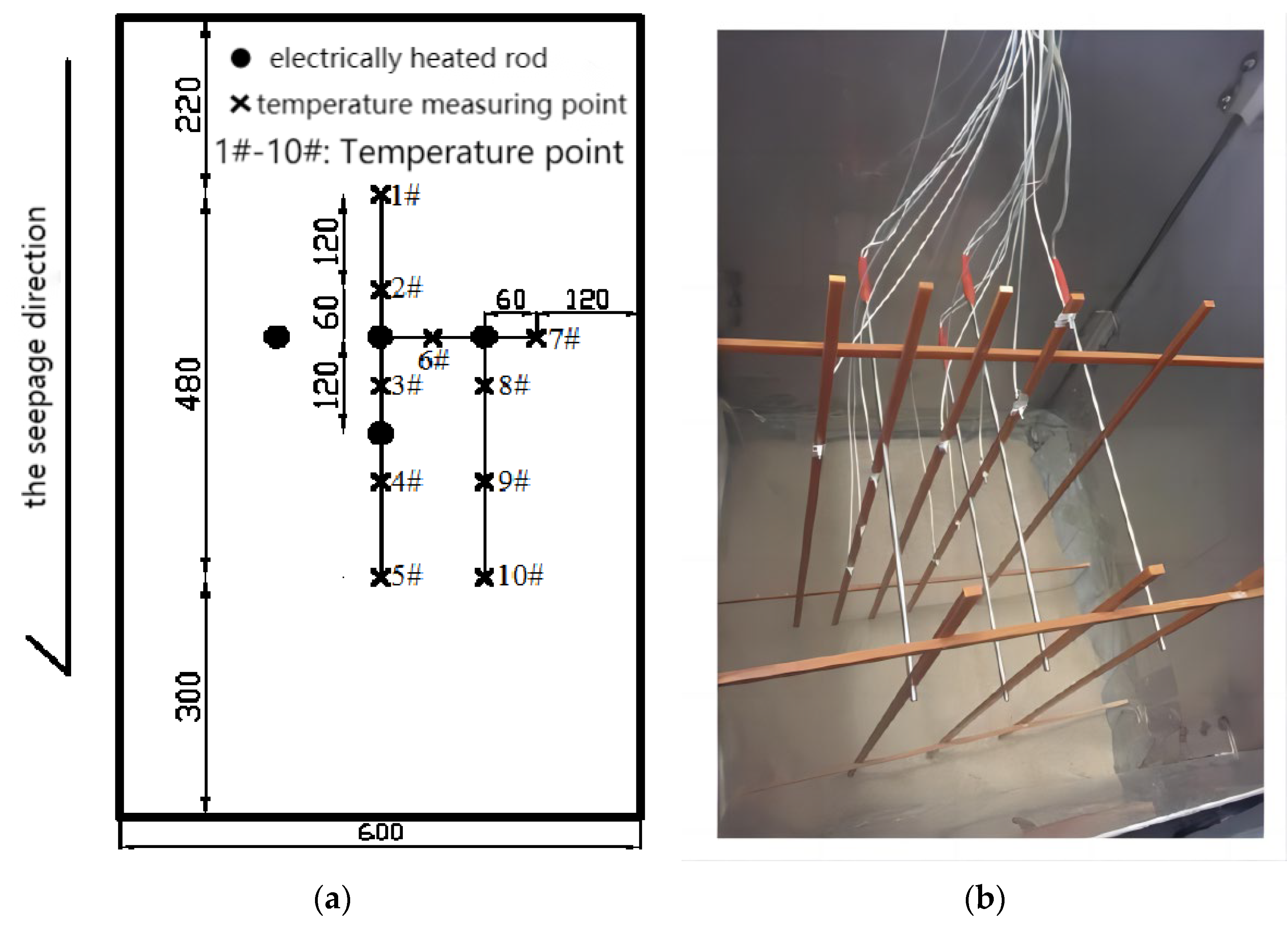
In practical projects, GSHP usually adopts borehole groups to exchange more heat with the soil. Different from a single borehole, heat transfer among different boreholes in a group can influence each other. To study the heat transfer characteristics of the borehole group, the heating wires or the tubes with water flowing inside were used as heat exchangers to conduct sandbox experiments. The use of heating wires in the experiments facilitated the emulation of boreholes with a constant heat transfer rate, making the apparatus setup and operational procedures relatively straightforward. In contrast, the configuration involving tubes with flowing water in the boreholes, although more complex than the heating wire setup, enabled not only the emulation of a constant heat flow condition but also the investigation of the impact of different parameters (such as inlet water temperature and circulating water flow rate) on heat transfer. Zhang et al. [59] set up a test rig, employing a stainless steel sandbox with dimensions of 0.6 × 0.6 × 1 m, as shown in Figure 7. The sandbox was constructed using 2 mm thick stainless steel plates and covered with 3 cm thick insulation material to ensure adiabatic conditions. The waterproof electric heating rods were adopted with a length of 0.4 m and a diameter of 6 mm. One electric heating rod was positioned upstream to conduct the single borehole experiment, while three additional electric heating rods were placed on the left, right, and back sides of the former rod. Together, these four electric heating rods were employed to investigate the heat transfer within borehole groups.
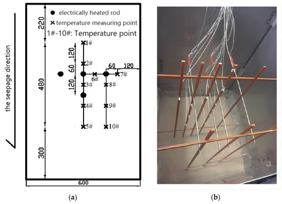
Figure 7.
Schematic diagram of a borehole group experiment with electric heating rods [59]. (a) Layout of heating rod and temperature sensor. (b) Image of heating rod and temperature sensor.
The soil temperature distributions of the single borehole and the boreholes group with seepage and non-seepage were tested. With the same heating capacity of the heating rod, the temperature rise and thermal storage capacity of the saturated soil are higher and larger than those of the dry soil. Figure 8 shows the variations in soil temperature under different seepage velocities, assuming each heating rod has a heat capacity of 20 W. Due to the movement of heat within the soil towards the seepage direction, the temperatures in the middle and downstream regions are relatively high, and the thermal exchange is intensified by the presence of seepage. Therefore, the borehole spacing in the seepage direction should be increased as much as possible to alleviate the heat accumulation in the borehole groups.

Figure 8.
Temperature variation of measuring points under different seepage velocities [59]. (a) 1 × 10⁻⁶ m/s; (b) 5 × 10⁻⁶ m/s; (c) 1 × 10⁻⁶ m/s.
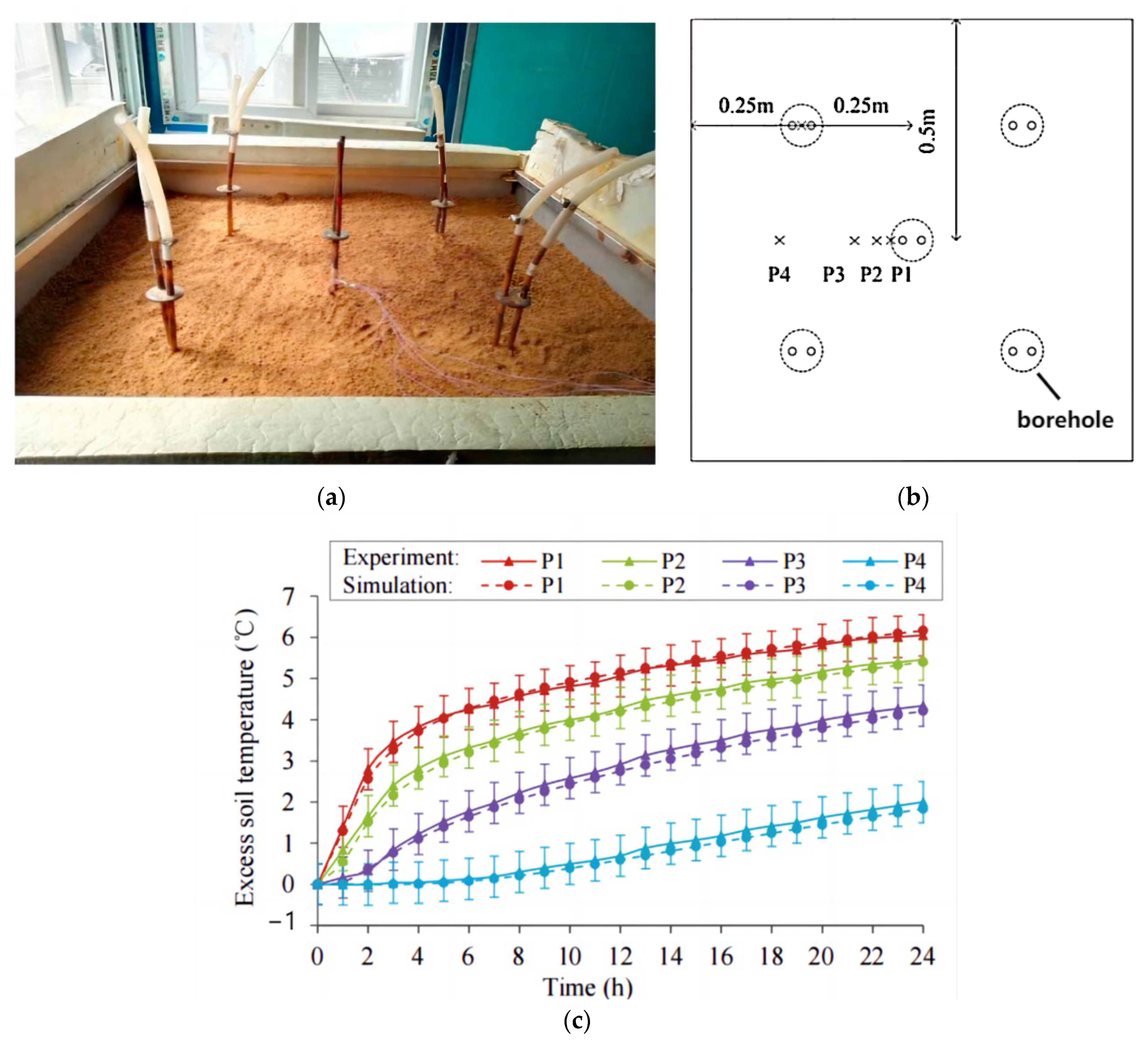
Different from Zhang et al. [59], who conducted a borehole tube group experiment using electric heating rods, You et al. [70] conducted their experiment using a borehole group consisting of five U-shaped tubes with circulating water. The test rig consisted of a sandbox, a water bath with a constant temperature supply, thermocouples, a glass rotameter, and a data logger. The sandbox was designed with a size of 1 × 1 × 1 m, with the five U-tubes buried inside (Figure 9b). The initial temperature of the sand was 21 °C, while the U-shaped tube’s inlet water temperature was maintained at 31 °C. The total water flow rate was constant at about 4 L/min. Four T-type thermocouples were placed near the central tube at a depth of 0.5 m to monitor soil temperature variations at typical locations, as shown in Figure 9b. Figure 9c illustrates the soil temperature changes at typical points after 24 h of operation, with the tube wall temperature (P1) decreased by about 6 °C. The soil temperature of P4, which is located 25 mm away from the tube, decreased by about 1.5 °C after the 24 h operation. These results can verify the heat transfer calculation model developed for the borehole group.
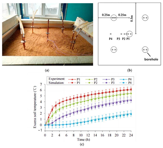
Figure 9.
A borehole group sandbox experiment with U-shaped tubes [70]. (a) Image of the sandbox. (b) Layout of U-shaped tubes group. (c) Soil temperature comparison between experiment and simulation.
In conclusion, the research on borehole group experiments offers significant insights into the heat transfer behavior within borehole groups. By employing heating wires or tubes with flowing water as heat exchangers and strategically arranging the relative positions of the boreholes within the group, different operating conditions can be simulated, and the impact of different parameters on heat transfer can be analyzed. These findings are essential for gaining a deeper comprehension of heat transfer in borehole groups and for investigating parameter optimization to maximize energy efficiency.
2.3. Seepage Experiment
In practical projects, it is common to encounter horizontal seepage flows in vertically drilled boreholes. The seepage can take away the cold or heat upstream of the borehole group and consequently slow down the cold or heat accumulation inside the borehole group. For the sandbox experiments, the seepage in the radial direction of the borehole is modeled by the seepage flowing in a vertical or horizontal direction, which is called the sandbox experiment with vertical or horizontal seepage, respectively.
2.3.1. Sandbox Experiments with Vertical Seepage
In the sandbox experiment with vertical seepage, the radial seepage of the boreholes flows downwards due to gravity, and the boreholes themselves are positioned horizontally within the sandboxes. In order to regulate the velocity and distribution of seepage across the entire cross-section, a series of filter nets is introduced between the water chamber and the sand. By adjusting the number of filter nets and the water level in the high-level water tank, the seepage velocity can be effectively controlled. Next, we will discuss two sandbox experiments that specifically examine vertical seepage flows.
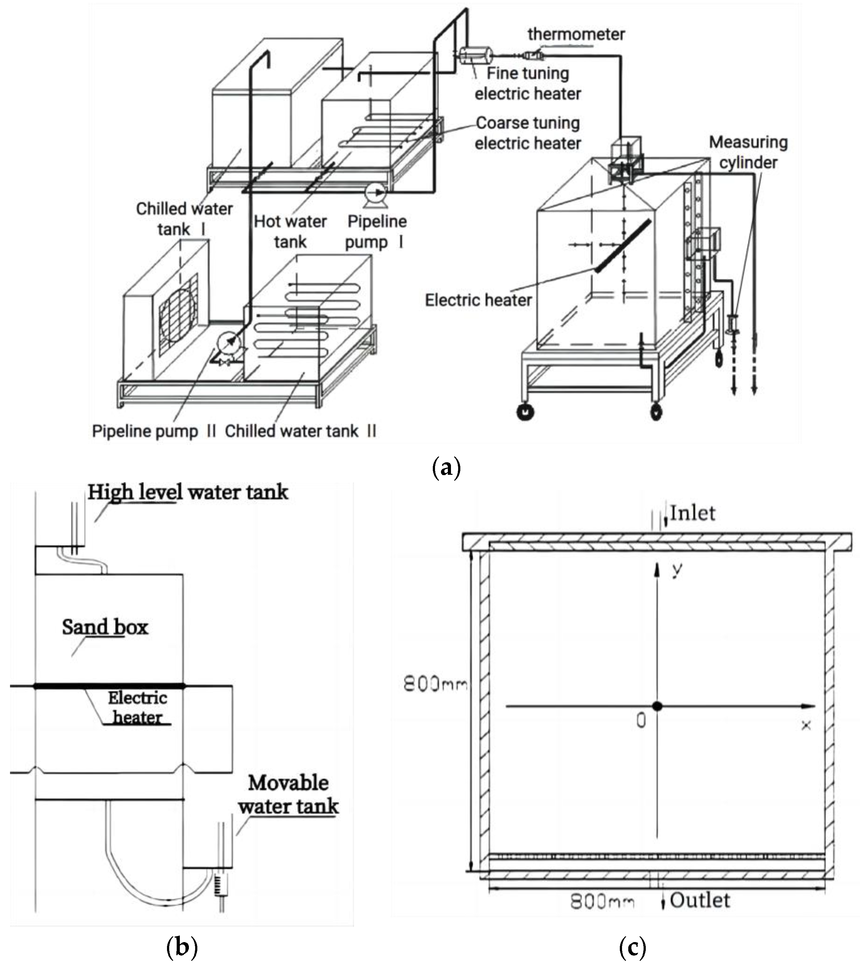
The first sandbox experiment involved regulating the seepage rate through the manipulation of the water tanks and valves. Liu et al. [60] set up a sandbox test rig with vertical seepage, as shown in Figure 10. The sandbox size was 0.8 × 0.6 × 0.77 m, and insulation materials were used to establish the adiabatic boundary condition. A heater with adjustable powers of 0~300 W was placed horizontally in the middle of the sandbox to emulate the borehole. The sandbox was connected to a fixed upper water tank and a movable lower water tank. By adjusting the relative height of the water tanks and corresponding valves, the different water head levels for seepage were achieved. As a result, the regulating valves could be employed to control the seepage velocities within the sandbox. The water in the sandbox flows out from the overflow tube of the moving water box, and the water seepage velocity in the sandbox can be obtained by measuring the flow rate. The research findings indicate that: (1) Seepage can improve the heat transfer capacity of the GHEs, resulting in smaller soil temperature variations around the borehole compared to saturated soil conditions. (2) Higher seepage velocities lead to reduced temperature fluctuations in the surrounding soil. (3) The soil temperature is no longer distributed in a circular shape, and the heat transfer increases along the seepage direction. Furthermore, the distance of influence expands with the growth of flow velocity.
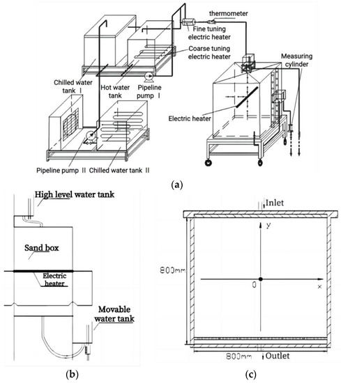
Figure 10.
Sandbox test rig with vertical seepage [60]. (a) System diagram of sandbox test bench. (b) Experimental setup. (c) Longitudinal section of sandbox.
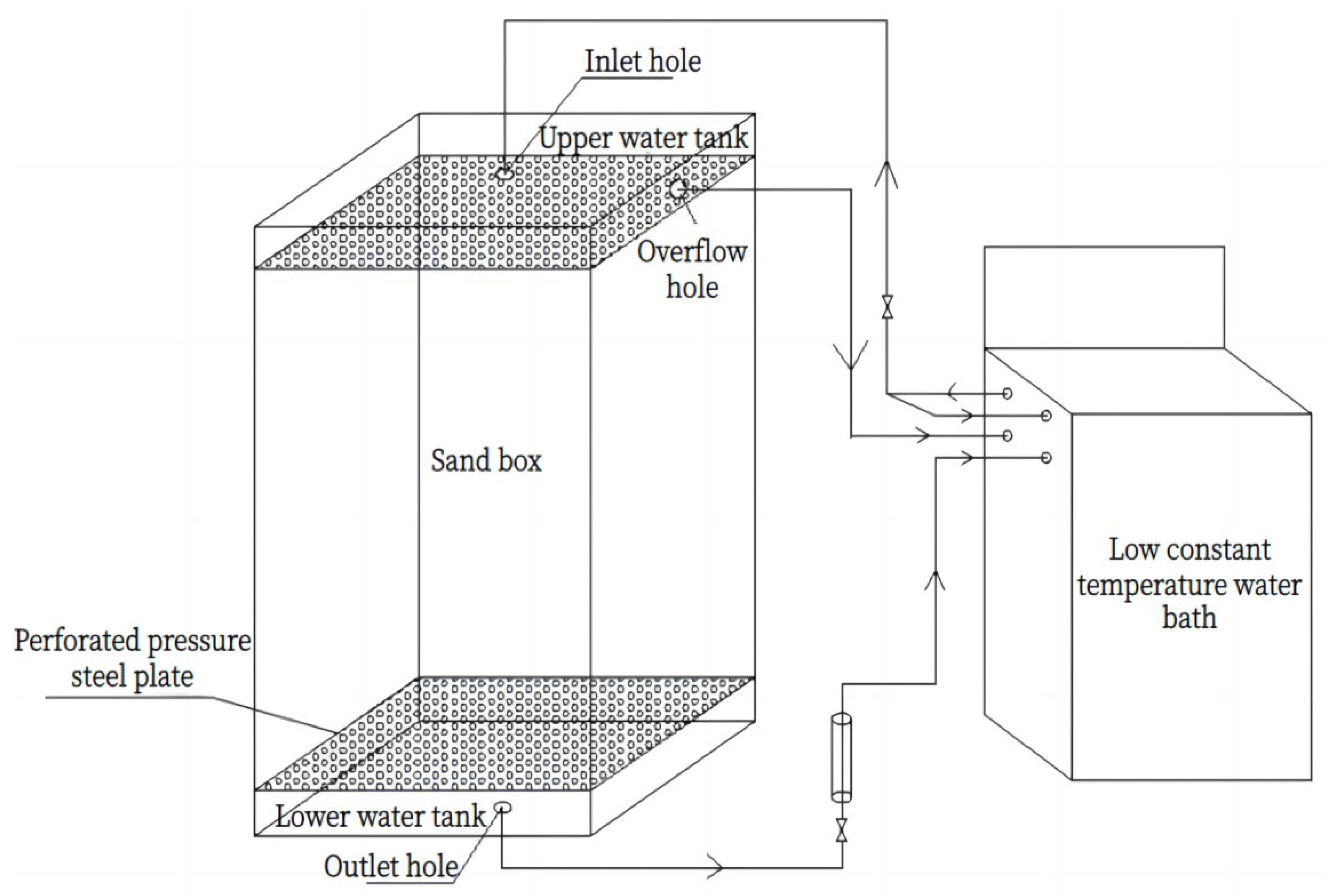
In contrast to the first sandbox experiment, which controlled the seepage rate by adjusting the water tanks and valves, another sandbox test rig with vertical seepage was built by Zhang et al. [59], as shown in Figure 11. The upper and lower sections of the sandbox were equipped with a 50 mm high water tank, and an overflow hole was positioned 40 mm above the liquid level of the upper water tank. To facilitate seepage, a steel plate with small drilled pores, covered with gauze to prevent sand loss, was used to separate the water tank from the sandbox. A glass rotor flowmeter was installed at the outlet of the water tank to monitor seepage velocities. To simulate the flow of vertical seepage, a horizontally positioned waterproof electric heating rod was employed as a substitute for the vertical borehole in this experiment. The schematic diagram of the electric heating rod and layout of temperature sensors in the experiment are shown in Figure 10a. Additionally, a water bath with a constant temperature was connected to the upper and lower water tanks to ensure that the sandbox attained the desired initial temperature. By adjusting the controlled temperature of the water bath, seepage at various temperatures could be achieved.
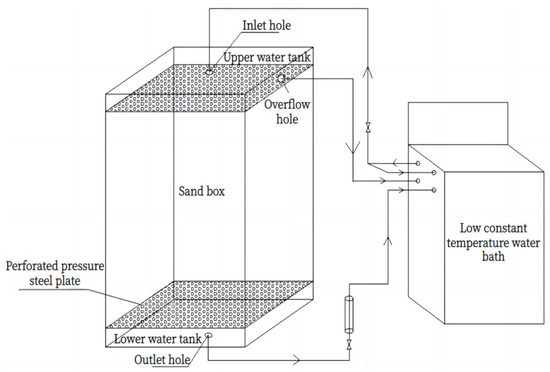
Figure 11.
Borehole group sandbox test rig with vertical seepage [59].
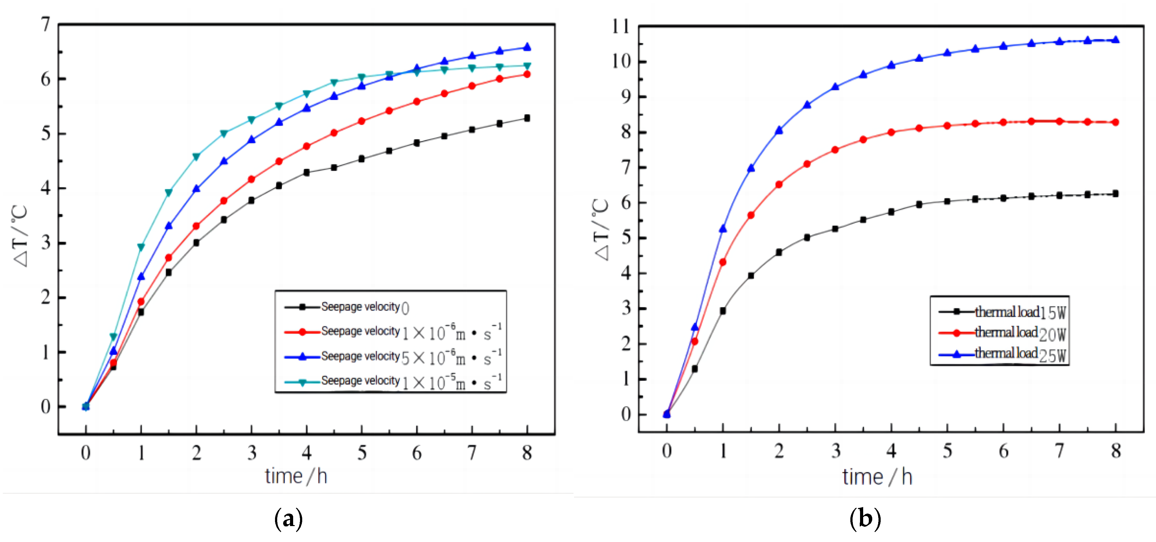
The experiment conducted by Zhang et al. [59] yields the following conclusions: Figure 12a shows the temperature variation of point 3 downstream of the electric heating rod under different seepage velocities when the heat dissipation rate of the electric heating rod was 15 W. It can be observed that the greater the seepage velocity was, the shorter the time needed to reach stability, and the lower the stability temperature was. Figure 12b shows the temperature variation of point 3 under different heat dissipation rates with a seepage velocity of 1 × 10⁻⁵ m/s. As the heat dissipation rate increases, the temperature at point 3 reaches stability in less time, and the temperature growth is higher.
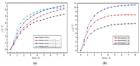
Figure 12.
Soil temperature variation of borehole group sandbox test rig with vertical seepage [59]. (a) Temperature variation of P3 under different seepage velocities with the heat dissipation rate of 15 W. (b) Temperature variation of P3 under different heat dissipation rates with the seepage velocity of 1 × 10⁻⁵ m/s.
Based on the aforementioned sandbox experiments involving vertical seepage, it can be concluded that achieving downward water flow driven by gravity is relatively straightforward, and the experimental operation is easily controllable. However, it should be noted that the simplified vertical seepage experiment may not fully capture the precise heat transfer characteristics of boreholes with horizontally radial seepage in practical projects.
2.3.2. Sandbox Experiments with Horizontal Seepage
In sandbox experiments involving horizontal seepage, water can flow horizontally by utilizing the pressure difference between the left and right sides of the sandbox. This mechanism is achieved by placing a water tank at a higher level on one side of the sandbox and a water tank at a lower level on the other side. The height disparity between the two water tanks facilitates the lateral flow of water from the higher tank to the lower tank, resulting in horizontal seepage. Additionally, the seepage velocity can be controlled by adjusting the height difference between the high and low tanks.
Li et al. [71] conducted a sandbox experiment with horizontal seepage, as shown in Figure 13. The rectangular sandbox had dimensions of 2.5 × 2.5 × 1 m, and the sandbox boundaries were maintained at a constant temperature by regulating the ambient room temperature. To ensure good thermal conductivity, a copper U-shaped tube was utilized as the heat exchanger, measuring 0.9 m in length, 0.02 m in diameter, and with a leg spacing of 0.04 m. The U-shaped tube received flowing water with the desired temperature from a constant-temperature water tank. Plastic plates were positioned on each side of the sandbox to create two water tanks, and eight tubes were installed to measure water pressures along the side wall at 20 cm intervals. To control the water levels, an overflow hole was positioned 0.95 m above the bottom of the tank on the right side of the sandbox. On the left side, there were 11 overflow holes with the same distance between them, facilitating control of the upstream water tank’s water level. The horizontal interval between adjacent overflow holes was 0.05 m, and the water level could vary from 0.90 m to 0.40 m. The difference in water level between the upstream and downstream tanks ranged from 0.05 m to 0.55 m, with intervals of 0.05 m. By manually manipulating the overflow hole switch, the seepage velocity could be adjusted according to requirements.
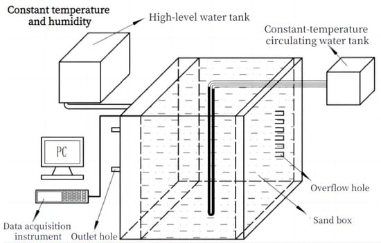
Figure 13.
Borehole sandbox test rig with horizontal seepage [71].
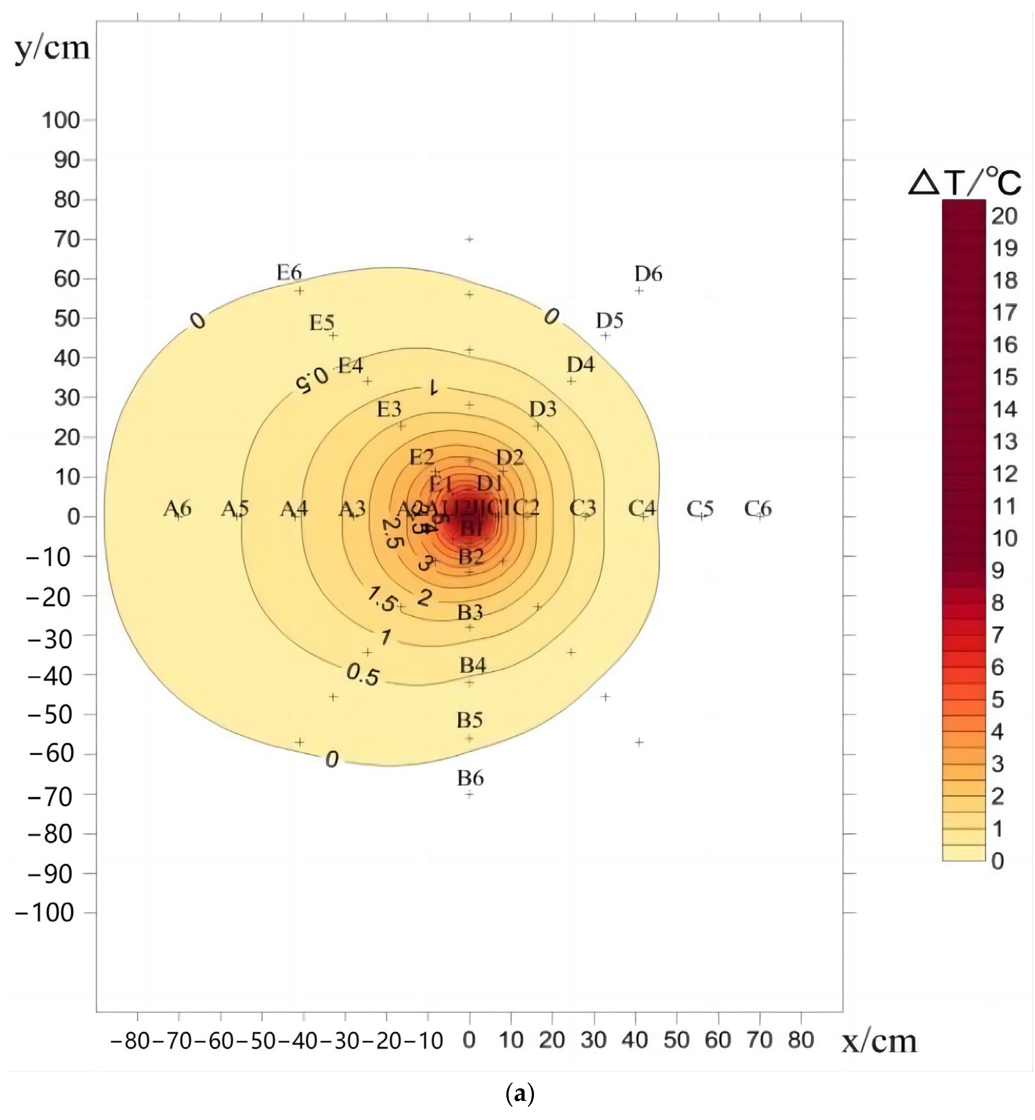
Based on the sandbox experiment on horizontal seepage conducted by Li et al. [71], the following conclusions can be drawn: Figure 14 presents the soil temperature distribution in the sandbox under different heat sources with a water level difference of 5 cm. The experimental results show that: (1) In the presence of seepage in the soil, the isothermal line is no longer circular and deviates downstream. (2) The soil closer to the heat source yielded a greater temperature gradient. (3) With an increase in the heat source temperature, the peak value of temperature variation shifts downward in the direction of seepage. The area with temperature change ∆T ≥ 0.5 °C is defined as the area with obvious temperature change. For heat source temperatures of 30 °C, 35 °C, and 40 °C, the areas exhibiting discernible temperature changes upstream in the sandbox measured 0.43 m, 0.37 m, and 0.44 m, respectively. On the other hand, the areas with noticeable temperature changes downstream measured 0.55 m, 0.45 m, and 0.70 m, respectively.
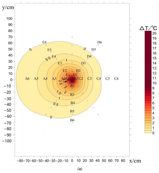
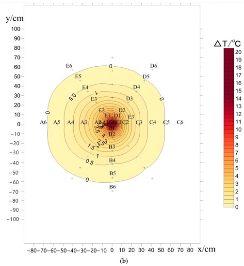
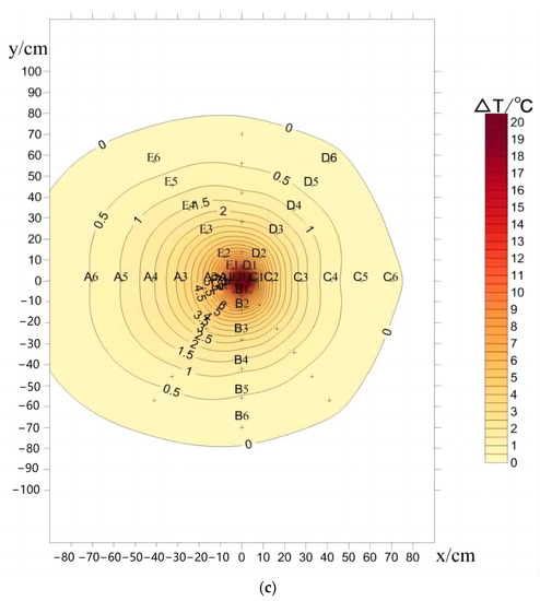
Figure 14.
The temperature distributions under different heat sources [71]. (a) 30 °C heat source; (b) 35 °C heat source; (c) 40 °C heat source.
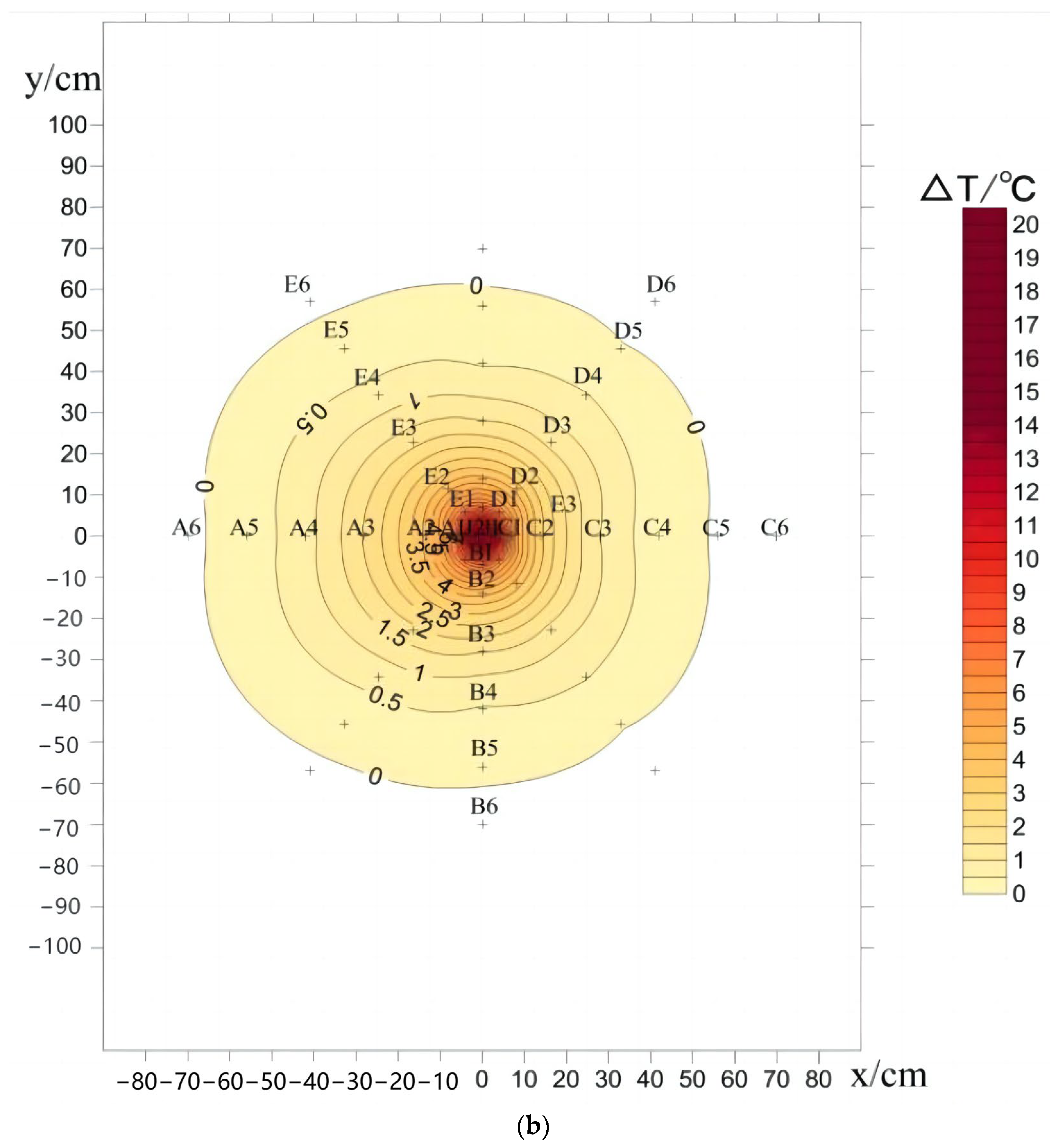
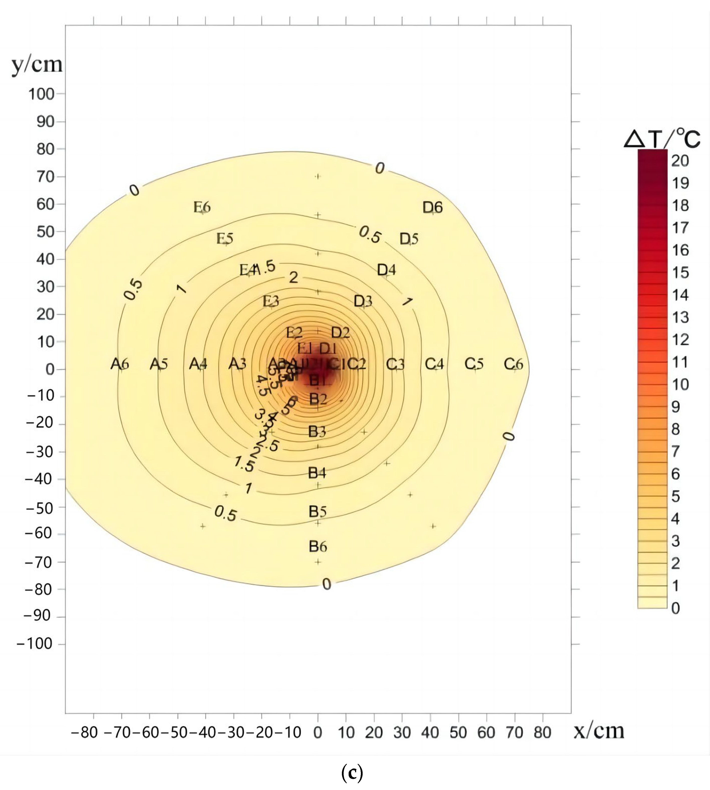
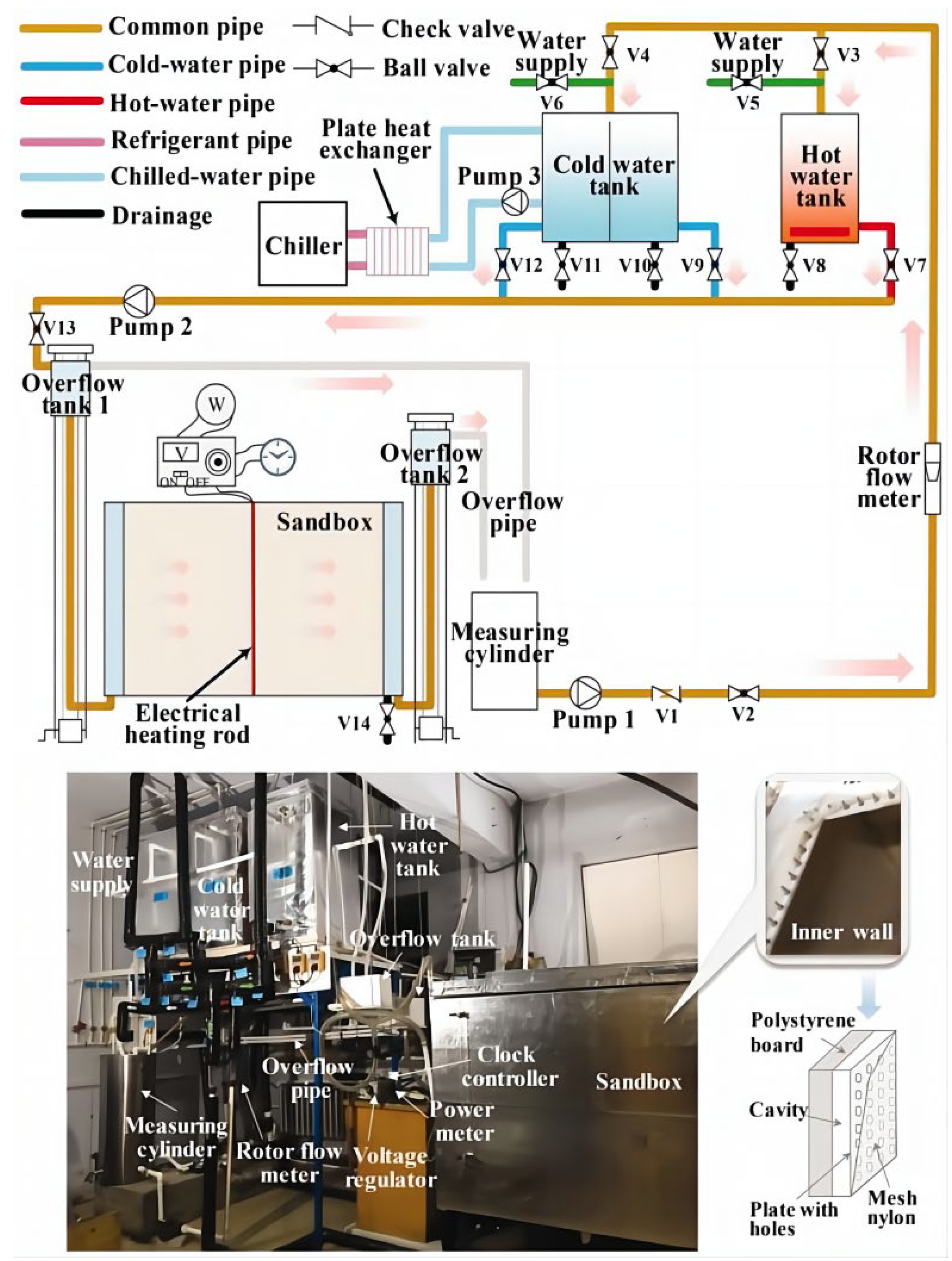
Different from the approach adopted by Li et al. [71], which involved using a U-shaped tube as the heat exchanger and constant-temperature water tanks on both sides of the sandbox to facilitate horizontal seepage flow, Wang et al. [72] developed a 1.5 × 1.5 × 1.0 m cuboid adiabatic sandbox with horizontal seepage, with the schematic diagram shown in Figure 15. To facilitate water seepage, two water chambers with a width of 0.15 m were constructed on opposite sides of the sandbox. The test rig consisted of three main parts: experimental sandbox, auxiliary water system, and data acquisition system. In the middle of the sandbox, a 200 W electric heating rod was positioned as the heat source. The operation of the heating rod was regulated by a timer, while its power was controlled using a voltage stabilizer. The auxiliary water system consisted of hot and cold water tanks, as well as an overflow tank, which were utilized to achieve the desired water temperature and pressure. A wired hose connected the overflow tank to the water chambers, allowing for water flow. The seepage velocity was found to vary in accordance with the height of the overflow tank.
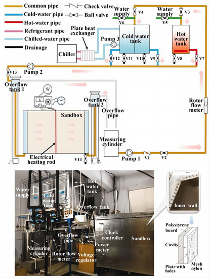
Figure 15.
Schematic diagram of a sandbox experiment with horizontal seepage [72].
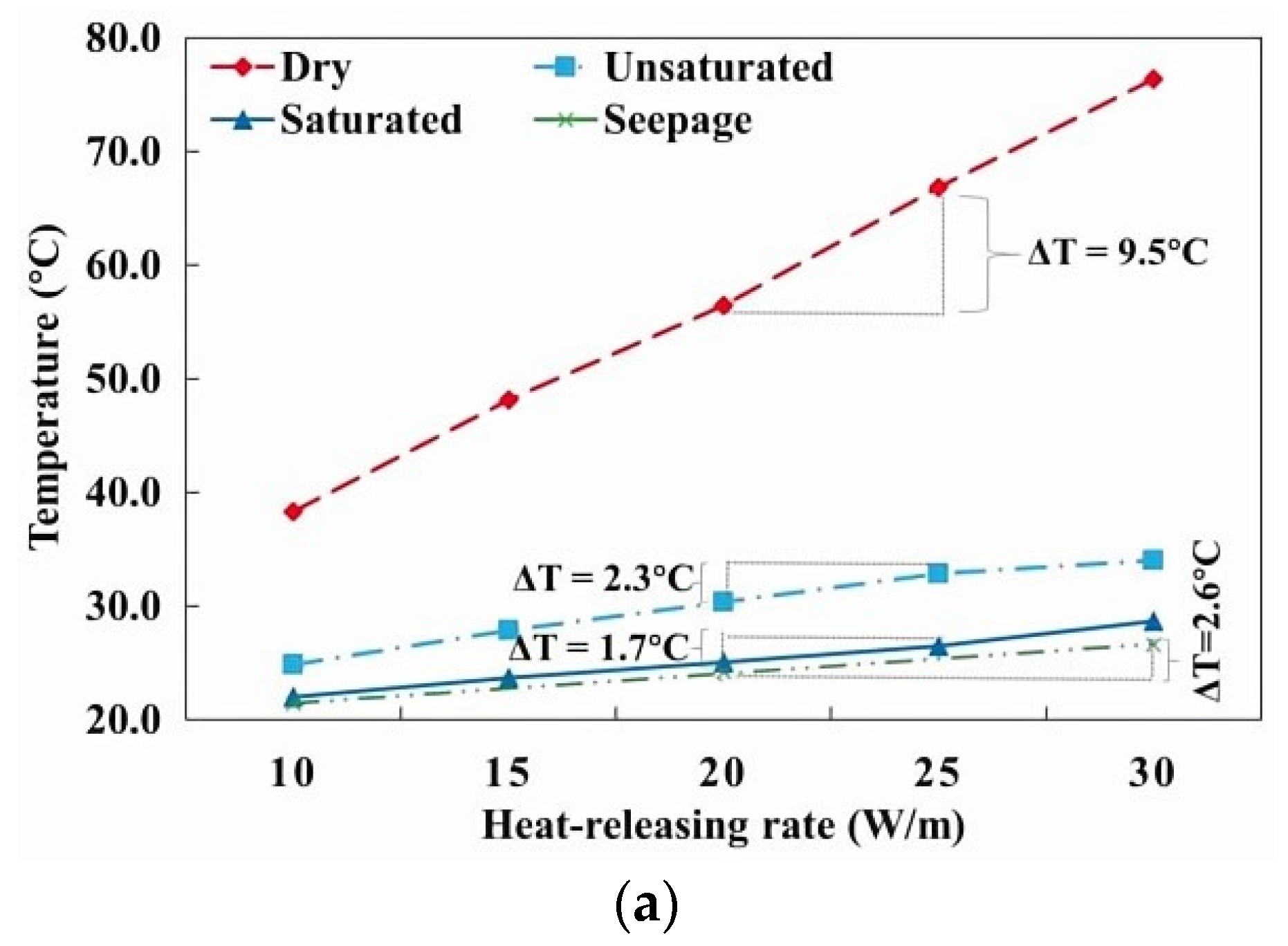
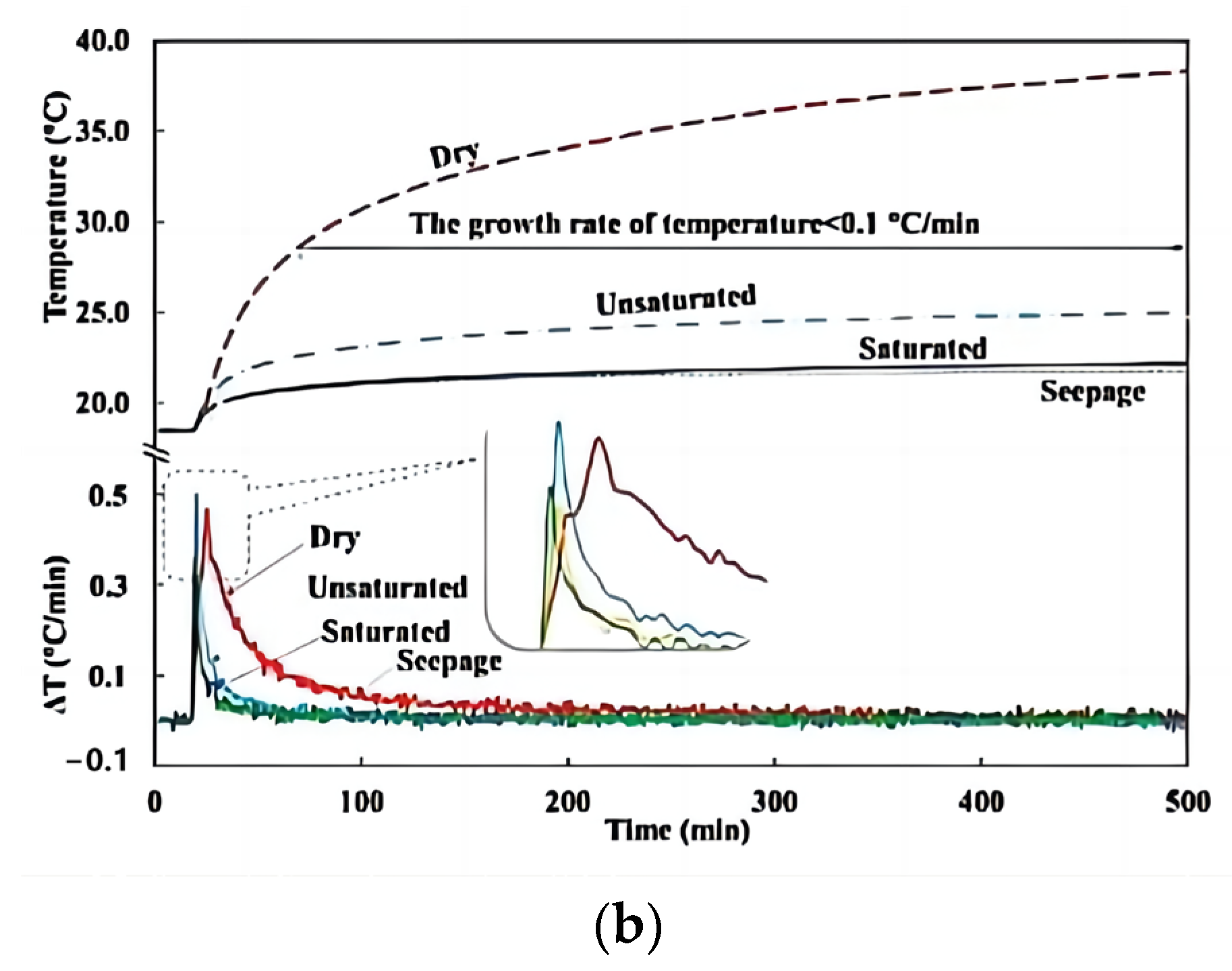
Wang et al. [72] performed sandbox experiments encompassing dry, unsaturated, saturated, and seepage sand conditions. Figure 16 presents the heating temperature and capacity of the electric heating rod under dry, unsaturated, saturated, and seepage sand conditions. For the electric heating rod with a heating power of 30 W/m, the heating temperatures could be 76.4 °C, 34.1 °C, and 28.7 °C under the dry, unsaturated, saturated, and seepage conditions, respectively. In addition, for a certain soil temperature, the heating capacity was proportional to the soil moisture content. As shown in Figure 16a, upon activation of the electric heating rod, the soil temperature initially increased rapidly before gradually stabilizing. Approximately 15 min later, the temperature growth rate remained below 0.1 °C/min and gradually stabilized with soil temperature increases of 1.5 °C and 2.0 °C under the seepage and saturated conditions. At a heat release rate of 10 W/m, a heat balance was quickly achieved between the electric heating rod and the soil in both seepage and saturated conditions. Following 8 h of heat release, the soil temperatures increased by 19.8 °C, 6.5 °C, 3.7 °C, and 3.2 °C under the dry, unsaturated, saturated, and seepage conditions, respectively. These results highlight the significant influence of soil water content on heat transfer within the soil. Soils with higher water content, particularly in seepage scenarios, exhibit a greater heat dissipation capacity and enable faster attainment of stable heat transfer.
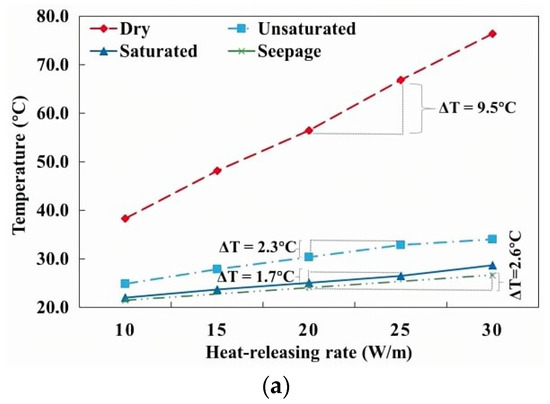
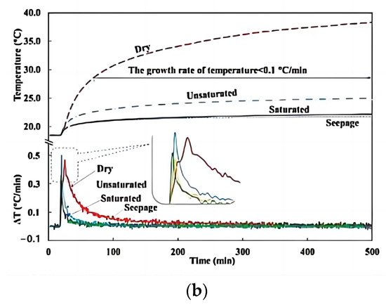
Figure 16.
Soil temperature change in sandbox [72]. (a) Relationship between heat dissipation rate and soil temperature. (b) Temperature variation at sandbox center.
Based on the aforementioned experiments, it can be inferred that the horizontal seepage experiment provides a relatively accurate representation of groundwater seepage in real-life projects. The seepage velocity can be regulated by manipulating the water levels in the high and low water tanks. However, in comparison to the vertical seepage experiment described in Section 2.3.1, the construction, operation, and measurement requirements of the test rig in the case of horizontal seepage are more intricate.
In conclusion, these seepage experiments offer valuable insights into the heat transfer characteristics of borehole systems in the presence of seepage. By conducting laboratory simulations of vertical or horizontal seepage, the study establishes that seepage conditions significantly improve the heat transfer efficiency of the borehole group. Moreover, it is observed that heat is preferentially transferred in the direction of seepage, effectively mitigating the cold or heat accumulation within the borehole group.
2.4. Multi-Layer Soil Experiment
In practical projects, boreholes typically have depths ranging from 50 to 120 m, and the soil is commonly composed of multiple layers. Different soil thermal properties also affect the heat transfer of boreholes in each layer of soil. To investigate the heat transfer characteristics in different soil layers, sandbox experiments involving multi-layered soil systems have been conducted.
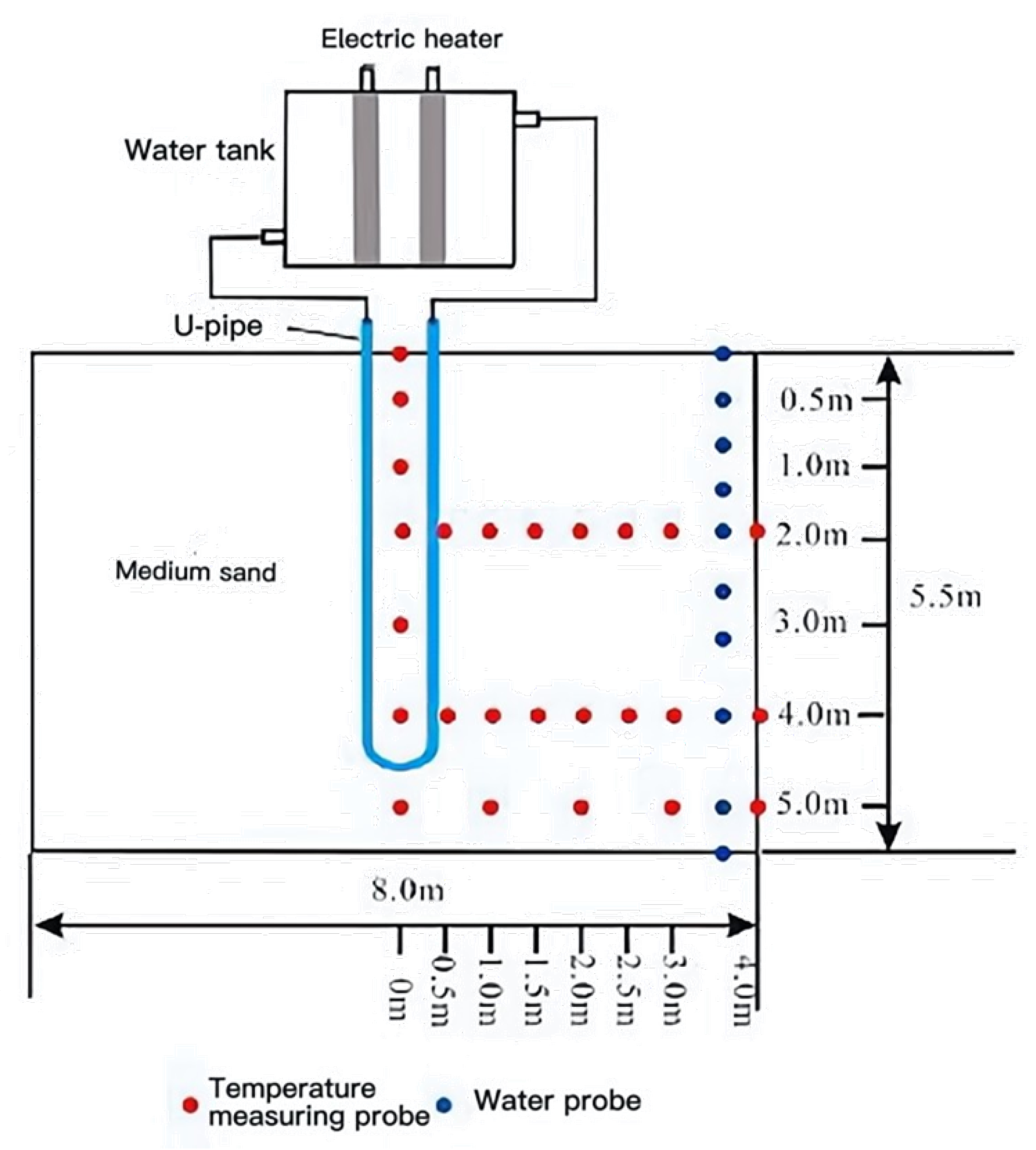
Wang et al. [61] constructed a cuboid sandbox bench of 8 × 6 × 5.5 m with adiabatic boundaries. The sandbox featured a three-layered soil structure, a sloping bottom equipped with a drainage system, a 0.5 × 0.5 m outlet on the lower side, and a pumping well. The U-type borehole adopted a high-density polyethylene (HDPE) tube with a diameter of 32 mm and was connected to a heating system (a field thermal response tester). The platform was equipped with a monitoring system to measure the moisture and temperature of the soil. As shown in Figure 17, the vertical arrangement incorporated seven temperature sensors situated at distances from 0 m to 5 m near the borehole, while three additional groups of temperature sensors were positioned horizontally at depths of 2 m, 4 m, and 5 m.
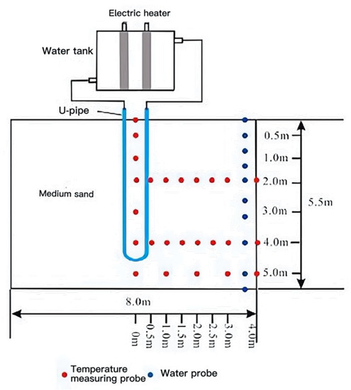
Figure 17.
Schematic diagram of thermal response experimental platform [61].
Through the sandbox experiment conducted by Wang et al. [61], the characteristics of heat transfer in different soil layers were investigated. The experiment commenced with an initial soil temperature of 13 °C, a heating power of 255 W, and a water flow rate of 9.6 m3/d, lasting for a duration of 10 days. The sandbox is originally filled with homogenous clay with a thermal conductivity of 0.52 W/(m·K). When the low-layer soil, initially having a thermal conductivity of 0.52 W/(m·K), was replaced with soil having a thermal conductivity of 4.23 W/(m·K), the outlet water temperature decreased from 37.07 °C to 35.05 °C, resulting in a notable 16.19% increase in the average heat transfer coefficient. Similarly, substituting the middle-layer soil with soil having a thermal conductivity of 4.23 W/(m·K) caused the outlet water temperature to decrease from 35.11 °C to 31.81 °C, accompanied by a 7% increase in the average heat transfer coefficient. Likewise, replacing the upper-layer soil with soil possessing a thermal conductivity of 4.23 W/(m·K) led to a decrease in the outlet water temperature from 31.82 °C to 28.95 °C, resulting in a 14% increase in the average heat transfer coefficient. Therefore, the soil properties in the lower layer exhibited the most significant influence on the overall heat transfer of GHE, whereas the impact of the middle-layer soil was relatively weaker.
In conclusion, this study highlights the significant role played by various soil layers in determining the overall heat transfer efficiency of GSHPs. When the thermal conductivity of the soil increases, there is an enhancement in the heat transfer capacity of the GSHPs, and the impact of the lower soil layers on heat transfer is particularly noteworthy. These findings demonstrate the importance of understanding and considering the thermal properties of different soil layers in designing and optimizing GSHPs.
2.5. Summary
The borehole sandbox experiments aim to investigate the impact of various factors such as tube type, borehole number, seepage, and multi-layer soil on the heat transfer performance of boreholes. Regarding tube type, the spiral tube demonstrates superior heat exchange performance compared to a single U-tube with the same drilling depth, and the heat transfer performance can be enhanced by enlarging the tube spacing and reducing the spiral pitch. Operation parameters such as flow velocity and inlet temperature also play a role in influencing heat transfer efficiency and soil temperature. The soil near the borehole exhibits rapid heat transfer and significant temperature gradients. In terms of soil parameters, seepage and thermal properties of soil layers also affect the heat transfer performance of boreholes. In different hydrogeological conditions (dry soil, saturated sand, and groundwater seepage), the thermal conductivity increases, and the thermal influential area expands successively, which is proportional to the thermal diffusivity. The thermophysical property of the low-layer soil has a greater impact on the overall heat transfer coefficient of the borehole compared to the up-layer and the middle-layer soils. The detailed research of the borehole sandbox experiment is shown in Table 1.

Table 1.
Research status on the boreholes sandbox experiment.
3. Energy-Pile Sandbox Experiment
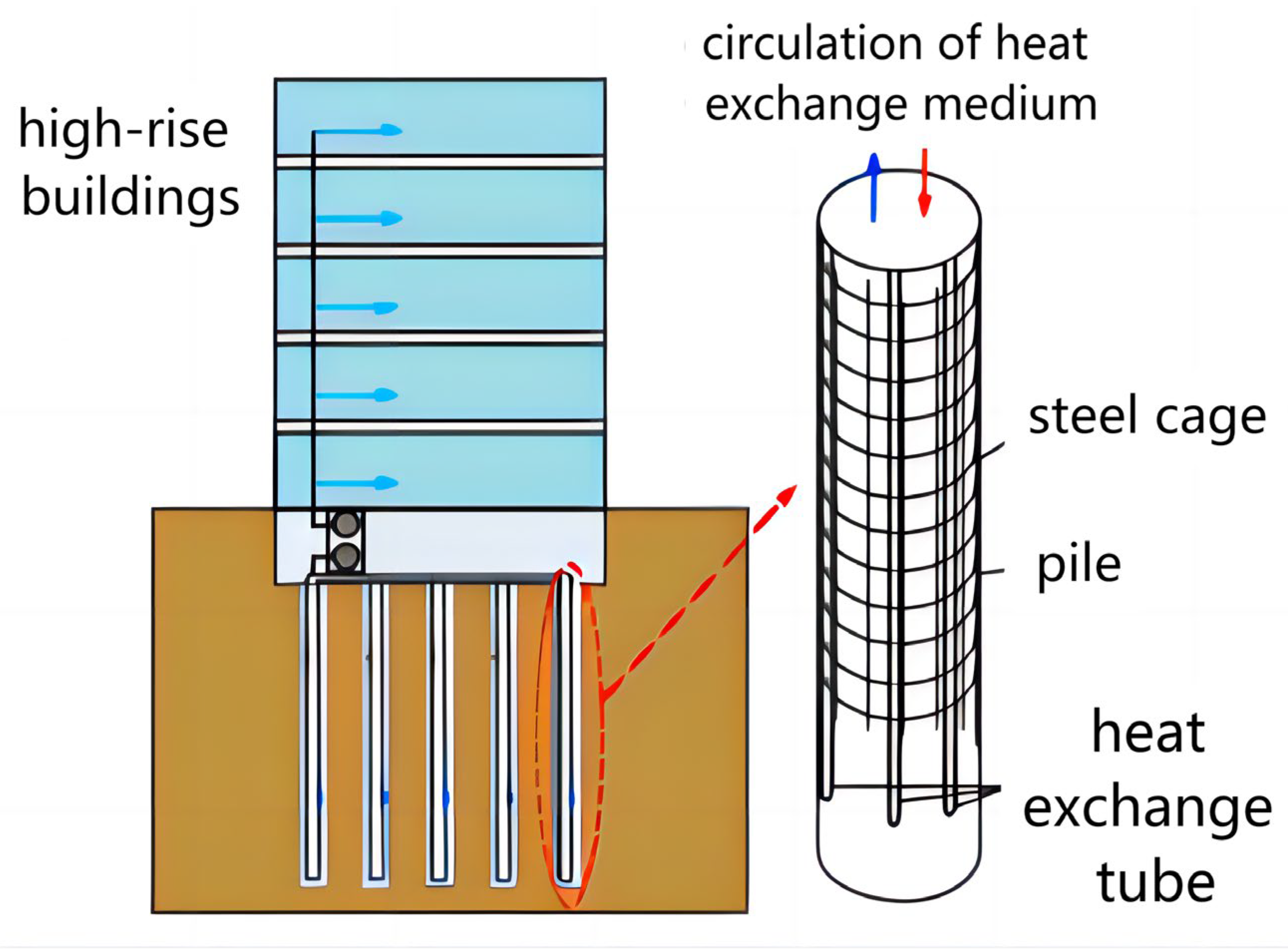
An energy pile refers to a type of building pile foundation that incorporates heat exchange tubes buried within it [73]. Compared to a borehole, an energy pile typically has a larger diameter and shorter length, resulting in a higher heat transfer rate. Consequently, energy piles have gained significant attention in recent years. Figure 18 depicts the schematic diagram of an energy pile [74]. The heat transfer characteristics of energy piles not only impact the mechanical properties of the piles but also have a significant influence on the energy performance of the GSHP system [75,76]. Therefore, the mechanical performance [56,57,58], thermal performance [77,78,79,80,81], and coupled thermal-mechanical performance [82,83,84] are carried out by sandbox experiments.
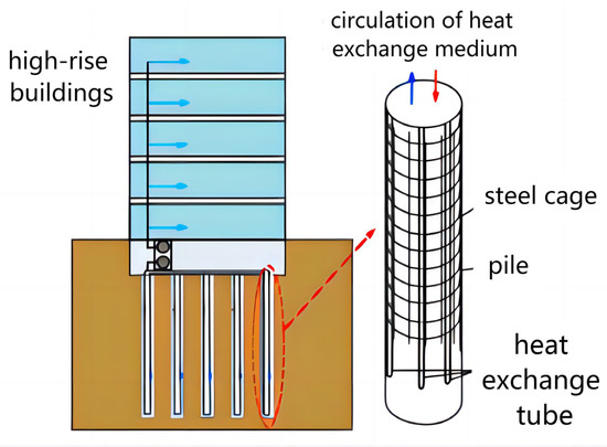
Figure 18.
Schematic diagram of energy pile [74].
3.1. Mechanical Performance Testing of Energy Piles
The heat transfer within energy piles has a direct impact on the bearing capacity of the building pile foundation, which is of paramount importance to the structural integrity of buildings. Hence, sandbox experiments on energy piles are conducted to examine the mechanical performance of the building pile foundation. Many experiments have specifically concentrated on investigating the effects of thermal cycles and pile head loads on the settlement of the pile foundation, axial stress in the pile body, and the frictional resistance between the pile and soil.
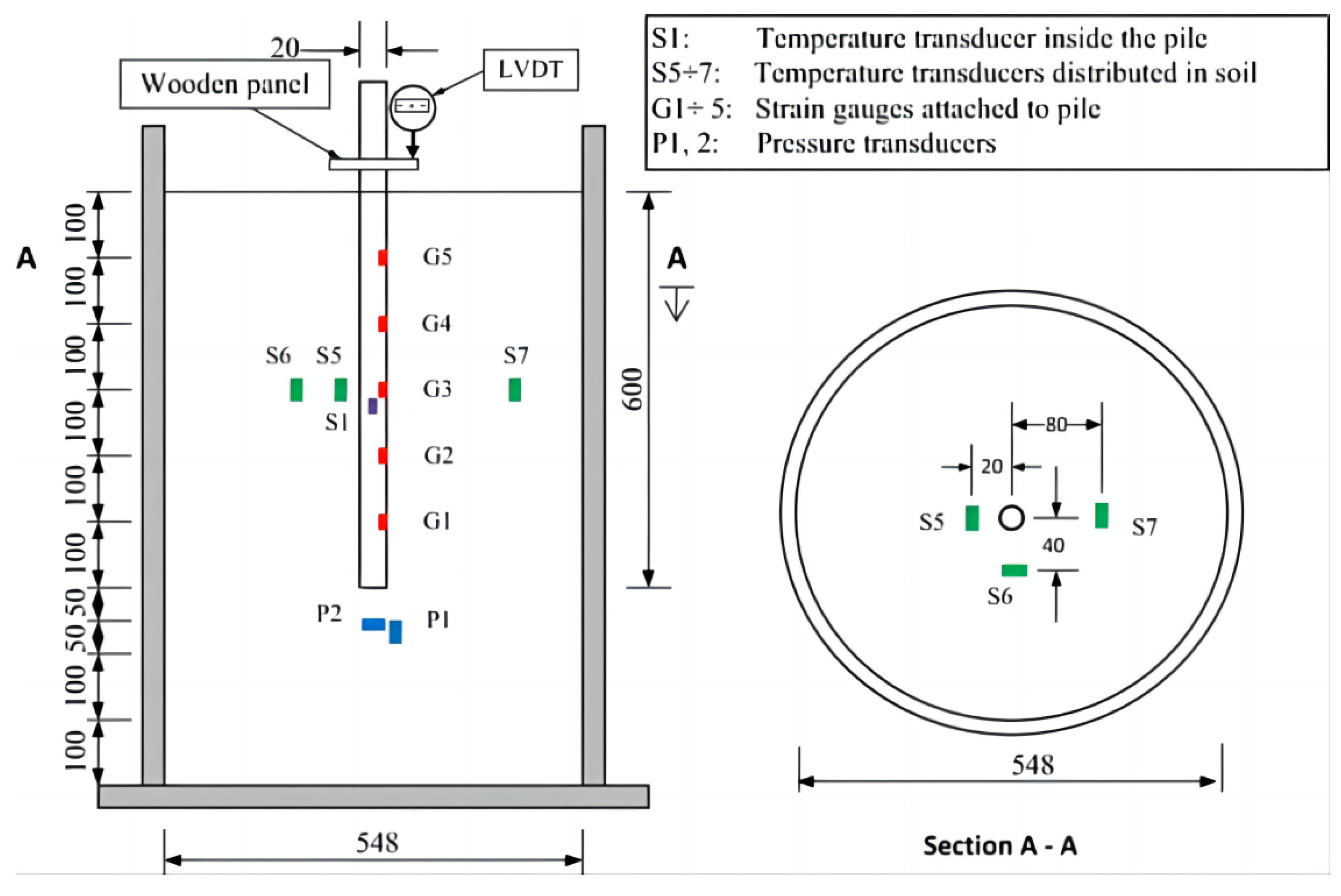
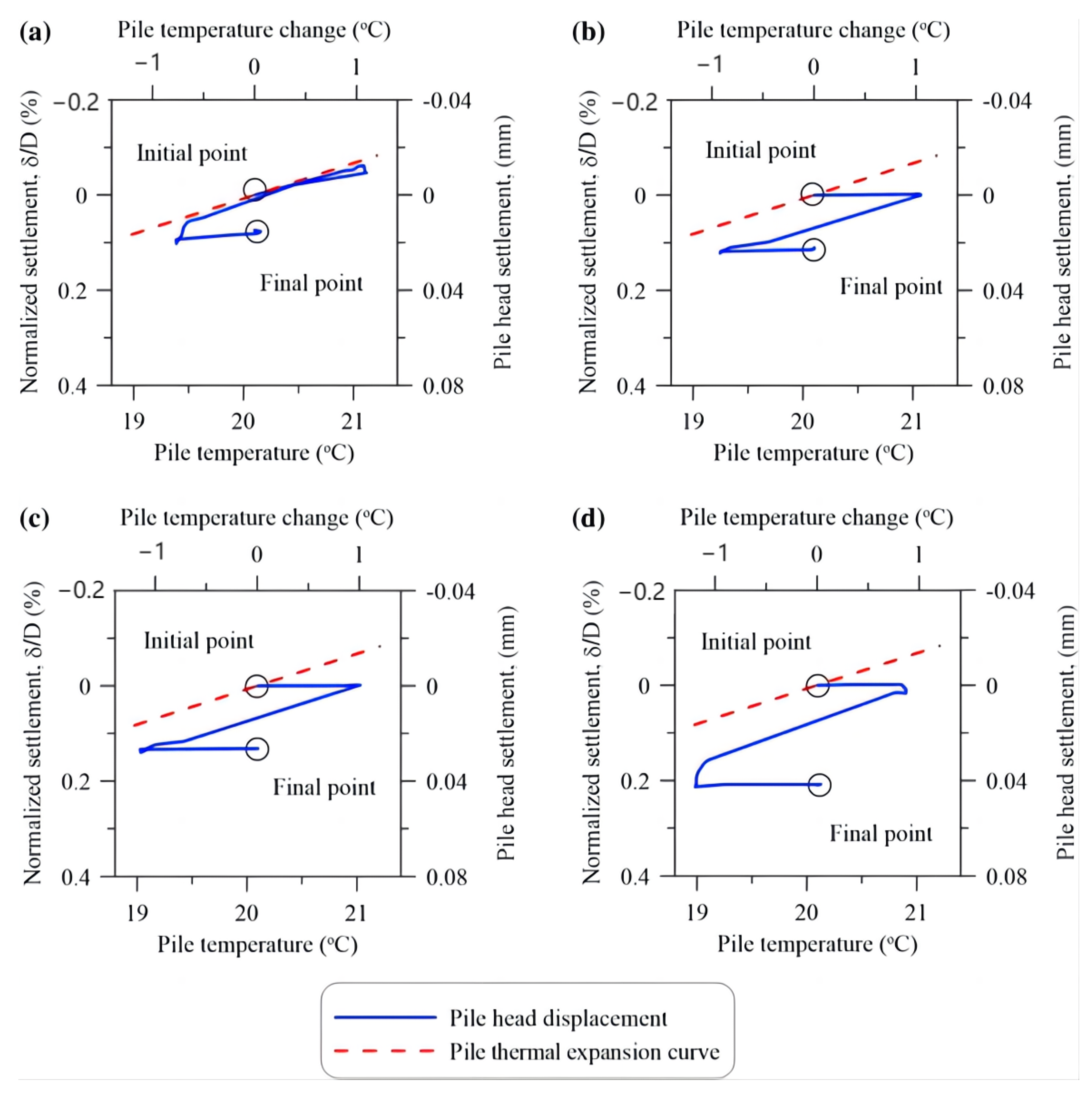
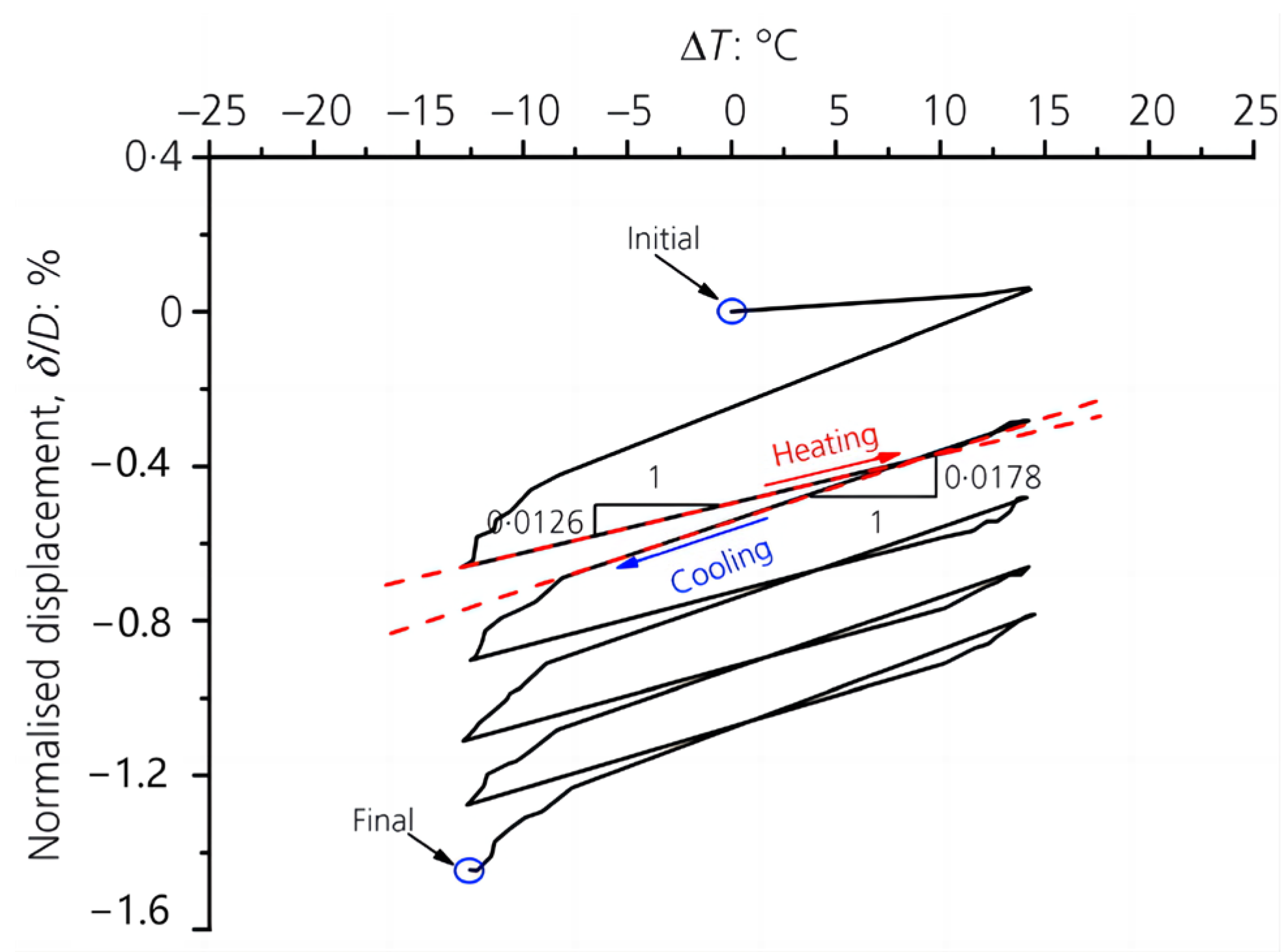
Nguyen et al. [56] conducted a mechanical test of an energy pile model using a sandbox with a diameter of 584 mm and a height of 900 mm under long-term thermal cycles to investigate the effect of the thermal cycles and the load on the settlement and forces in the pile, as is shown in Figure 19. In the experiment, the piles were subjected to loading and unloading with pressures ranging from 10% to 100% of the maximum load (approximately 50 N) with a 10% interval. Each loading phase lasted for one hour, and the process was repeated until the pile head settlement reached 10% of the pile diameter. Simultaneously, the researchers conducted 30 thermal cycles under four different conditions (10%, 20%, 40%, and 60% of the maximum load), with each cycle lasting for 24 h to examine the bearing characteristics of the piles under thermal cycling. The results demonstrate that the settlement of the pile, both under mechanical loads with and without thermal cycles, increases as the load magnitude increases. The heating process of the pile does not cause significant movement of the pile body, while the cooling process induces pile settlement. Both processes are irreversible, except when the load is zero, as illustrated in Figure 20. Additionally, the settlement rate of the pile experiences substantial changes in the first 10 cycles and gradually stabilizes afterward. Moreover, the axial force along the pile body increases with an increasing number of thermal cycles.
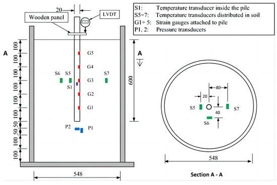
Figure 19.
A mechanical energy pile experiment with a cylindrical sandbox [56].
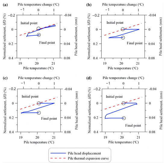
Figure 20.
Relationships between pile head settlement and temperature in the first cycle with different axial load ratios: (a) 0%; (b) 20%; (c) 40%; (d) 60% [56].
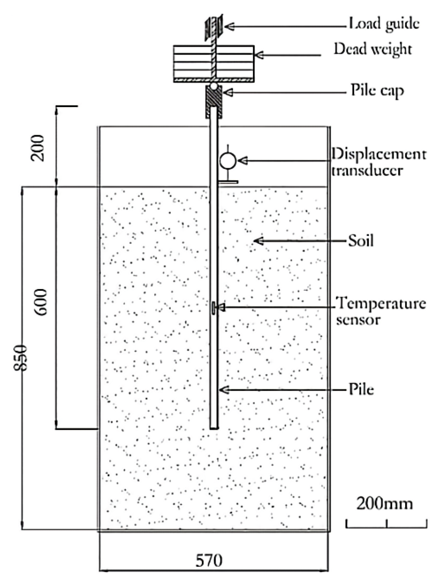
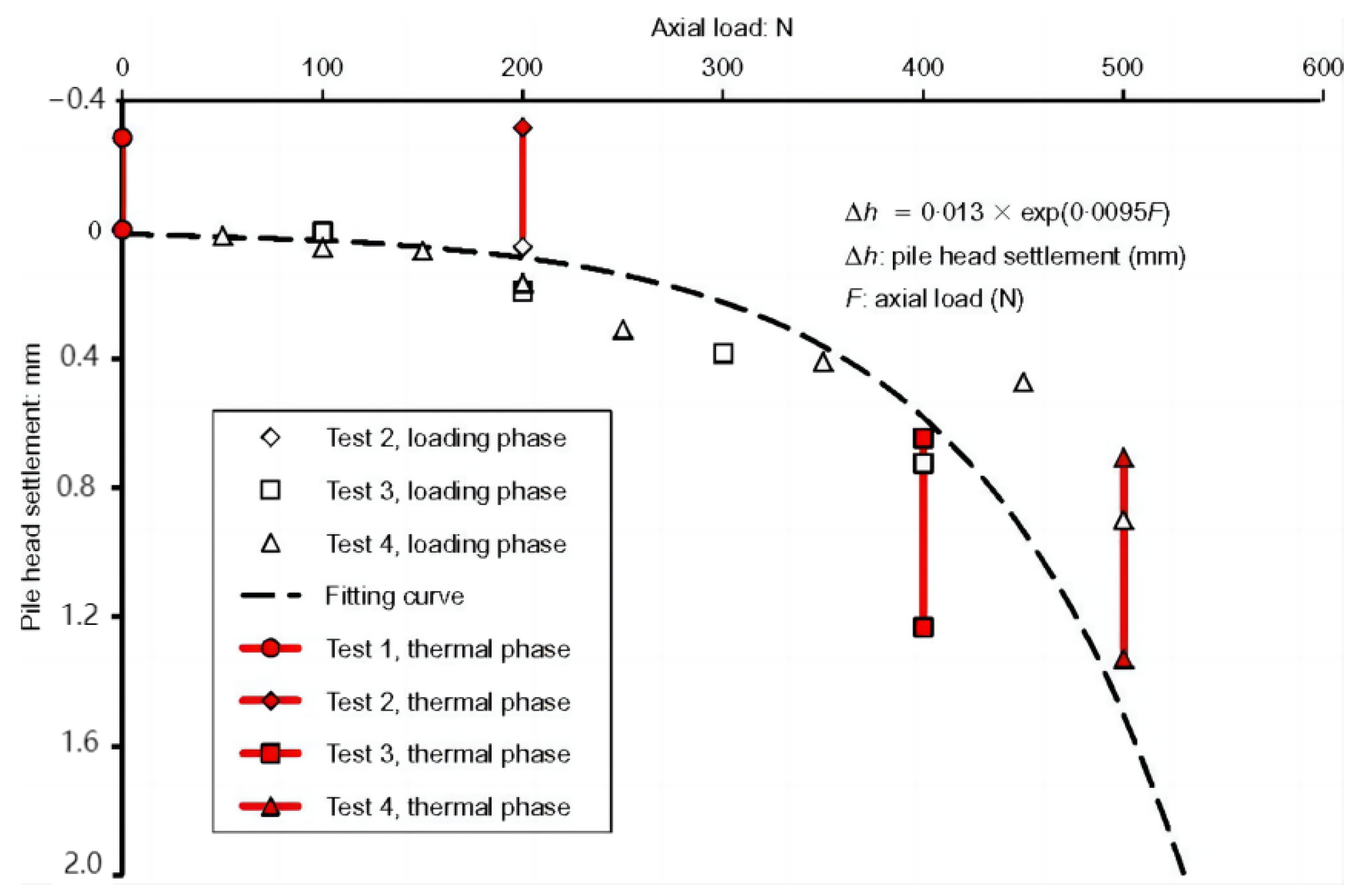
Kalantidou et al. [57] conducted a sandbox experiment to study the mechanical properties of energy piles in 2012, which focused on the effect of applied loads and temperature on the settlement of energy piles. Figure 21 illustrates the schematic diagram of the experiment, which involved the use of a cylindrical steel sandbox with a diameter of 570 mm. The experimental setup consisted of a closed aluminum tube placed outside the model pile, while a metal U tube with a total length of 800 mm was placed inside the pile. The researchers aimed to investigate the relationship between the load and displacement under different head loads. In the experiment, assuming the internal temperature of the pile remained constant, four different loads (0 N, 200 N, 400 N, and 500 N) were applied. Each test underwent thermal cycles, starting from 25 °C, increasing to 50 °C, and then returning to 25 °C, repeating this cycle twice.
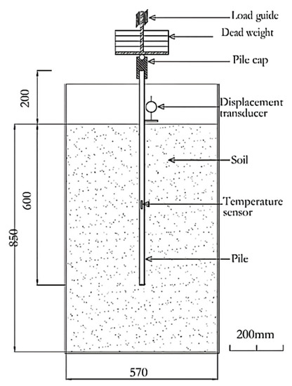
Figure 21.
A mechanical energy-pile experiment in a steel sandbox [57].
Figure 22 demonstrates the pile head settlement under the axial load with and without thermal cycles, and the results show that pile settlement is influenced by the coupling of temperature and load. The experimental results indicate that increasing the head load leads to a larger settlement of the pile body. The relationship between displacement and the temperature of the pile body during the first heating/cooling cycle resembles the thermal expansion and shrinkage curves of the pile body, respectively. Furthermore, the pile body exhibits a normal thermal response when the head load is below 40% of the maximum load. However, if the head load exceeds 40% of the maximum load, the settlement of the pile body accumulates under thermal cycles, potentially leading to safety hazards.
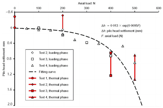
Figure 22.
Load-settlement curves under the axial load with and without thermal cycles [57].
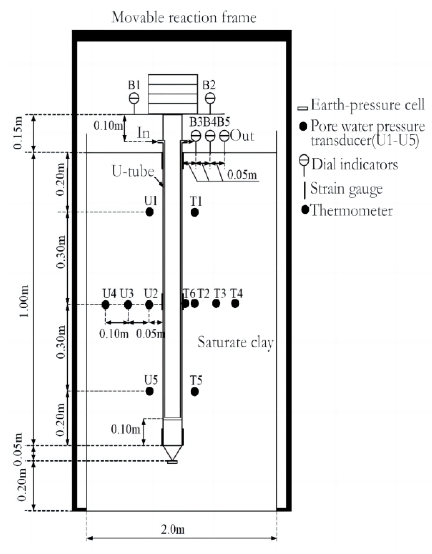
Qian et al. [58] conducted an energy pile sandbox experiment using a cuboid sandbox measuring 2 × 2 × 1.5 m to investigate the soil mechanical properties of energy piles. Figure 23 illustrates the diagram of the pile-soil sandbox experiment. The experiment utilized a single U-shaped energy pile with a diameter of 200 mm and a length of 1200 mm, subjected to a maximum load of 4000 kN. Throughout the study, the room temperature was maintained at 11 °C, and the heating temperature was set at 50 °C. The thermal cycling commenced after the completion of loading, and the settlement of the pile reached a stable state.
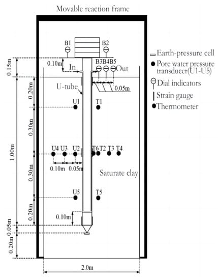
Figure 23.
A mechanical energy pile experiment with a cuboid sandbox [58].
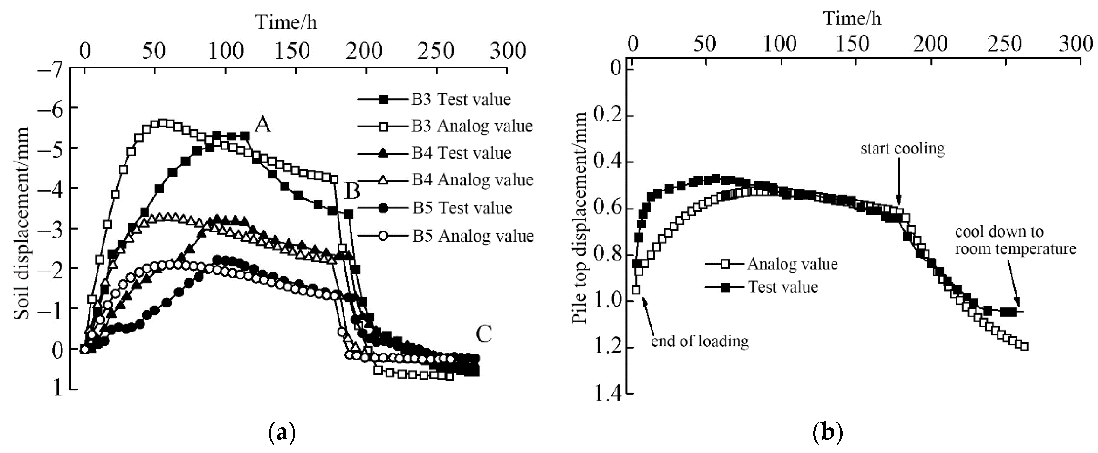
The internal forces within the soil and energy piles are primarily influenced by the temperature changes during the thermal cycle and the relative displacement between the soil and the energy piles. The experimental results reveal that the water pressure within the soil increases as the temperature rises during the thermal cycle. Figure 24 displays the displacement of the soil and energy piles over time. During the thermal cycle, the soil initially bulges upwards, followed by settlement as the temperature decreases, eventually reaching a lower height than its initial state. The pile body also experiences settlement, but its final settlement is less than that of the soil. This difference in settlement can lead to negative frictional resistance between the pile and the surrounding soil.
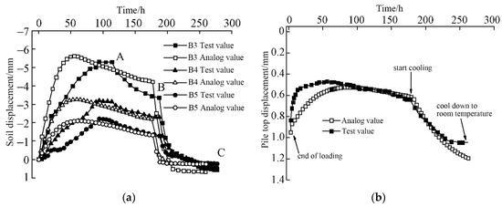
Figure 24.
Vertical displacement of ground surface and pile top (the uplift of the surface is negative, and the subsidence is positive) [58]. (a) Vertical displacement of ground surface. (b) Vertical displacement of pile top.
The conducted experimental results on the mechanical performance of energy piles demonstrate that the settlement, internal stress, and frictional resistance of energy piles are influenced by both pile head loads and thermal cycles, thereby exploring the service life and safety of energy piles. However, these experiments have certain limitations as they did not consider the coupled effects of various parameters. Experiments conducted by Nguyen et al. [56] and Kalantidou et al. [57] primarily focused on the influence of load magnitude, while experiments conducted by Qian et al. [58] emphasized the effect of relative displacement between the pile and soil. Therefore, further investigations considering the coupled effects of multiple parameters are necessary.
3.2. Thermal Performance Testing of Energy Piles
The thermal performance of energy piles plays a crucial role in determining the energy consumption of GSHP systems. However, the quantitative heat transfer laws derived from thermal performance experiments conducted on boreholes cannot be directly applied to energy piles due to their distinct size and structural differences. Consequently, numerous researchers have conducted sandbox experiments to analyze the impacts of various parameters, such as heat medium temperature, flow rate, intermittent operation, and geometric factors, on the thermal performance of energy piles. These experiments aim to provide insights into optimizing the thermal performance and energy efficiency of energy pile-based GSHP systems.
Kramer et al. [77] designed a single U-shaped energy pile to investigate its heat transfer characteristics. Figure 25 illustrates the schematic diagram of the sandbox used in the experiment. To achieve a consistent static stress in the soil surrounding the cast-in-place energy pile, sedimentation was employed.
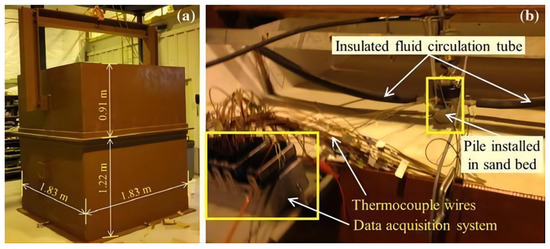
Figure 25.
The sandbox experiment with a U-shaped energy pile [77]. (a) Soil tank; (b) close-up view of assembled test setup with the model geothermal pile installed in the sand bed.
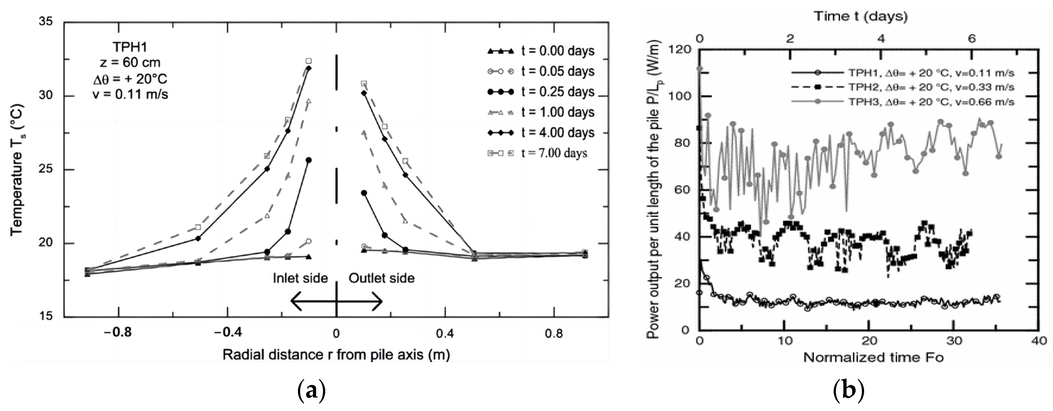
The temperature of the soil around the energy pile is influenced by the pile spacing and the type of energy pile. Figure 26a displays the soil temperature at various radial distances from the pile over a period of seven days. The heat transfer characteristics of a single U-shaped energy pile can be approximated as axisymmetric. Figure 26b demonstrates the impact of the circulating water flow rate on the heat transfer capacity of the pile. The results indicate that as the water flow rate increases, the heat transfer rate of the energy pile improves. However, excessively high flow rates can result in increased power consumption, which may negatively affect the seasonal performance of the system. Therefore, a balance must be struck between achieving optimal heat transfer and avoiding excessive power consumption.
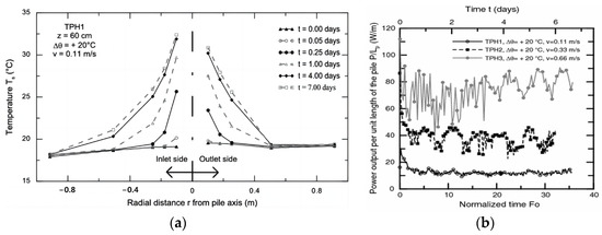
Figure 26.
Thermal performance of the energy pile [77]. (a) Soil temperatures at different radiuses. (b) Influence of circulating water flow.
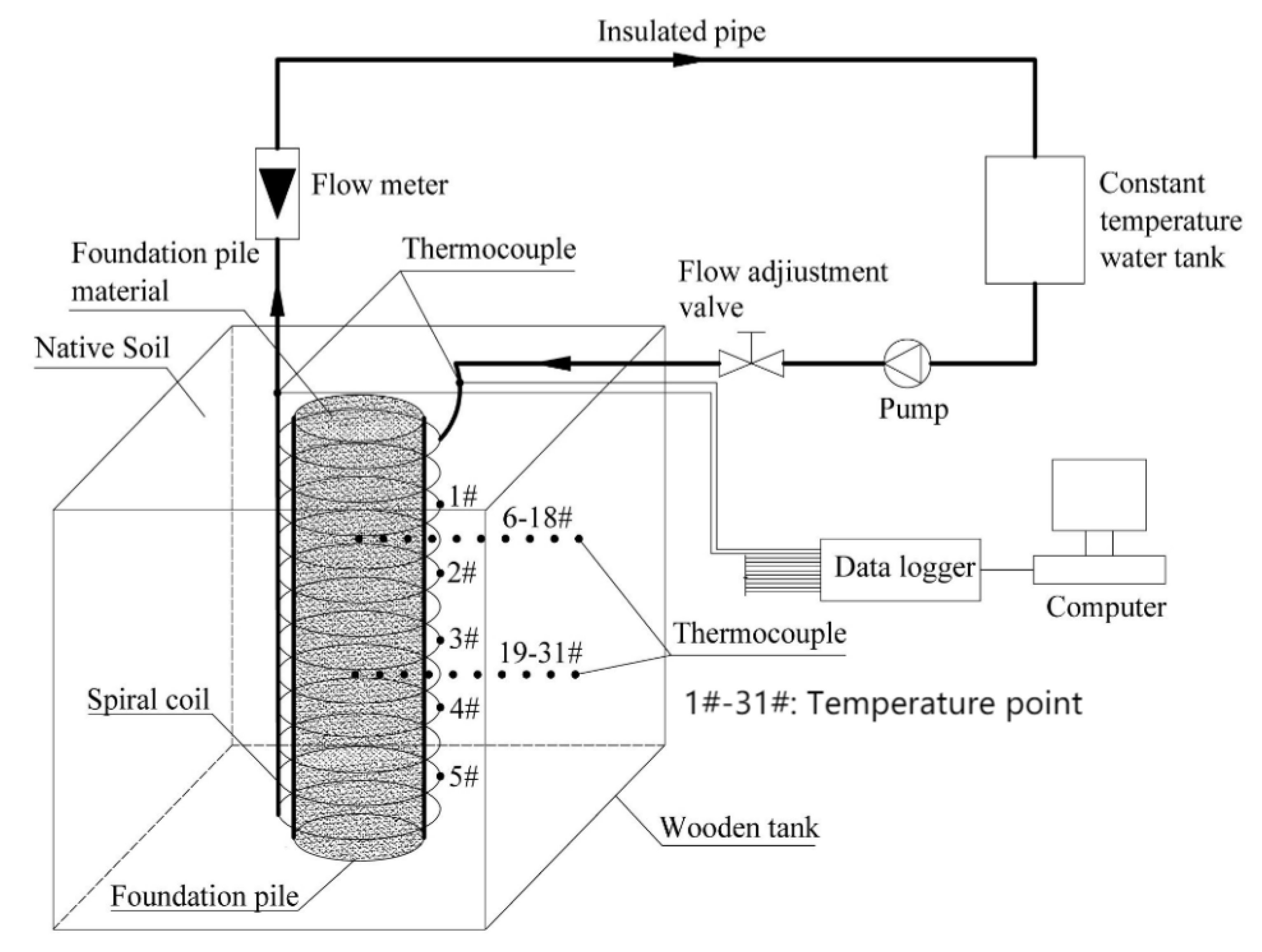
Yang et al. [79] experimented on the factors affecting the heat transfer efficiency of a spiral-coil energy pile, and a schematic diagram of the experimental system is shown in Figure 27. In the experiment, a wooden sandbox measuring 0.8 × 0.8 × 1.2 m was utilized, with 25 mm thick insulation materials covering both the top and bottom of the box. The spiral coil was constructed using a polyurethane tube with an outer diameter of 6 mm and an inner diameter of 5 mm, which was wrapped around the model of the pile foundation. The pile model itself was made of a polyvinyl chloride tube with an outer diameter of 200 mm and an inner diameter of 190 mm.
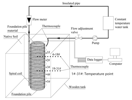
Figure 27.
The sandbox experiment with a spiral-coil energy pile [79].
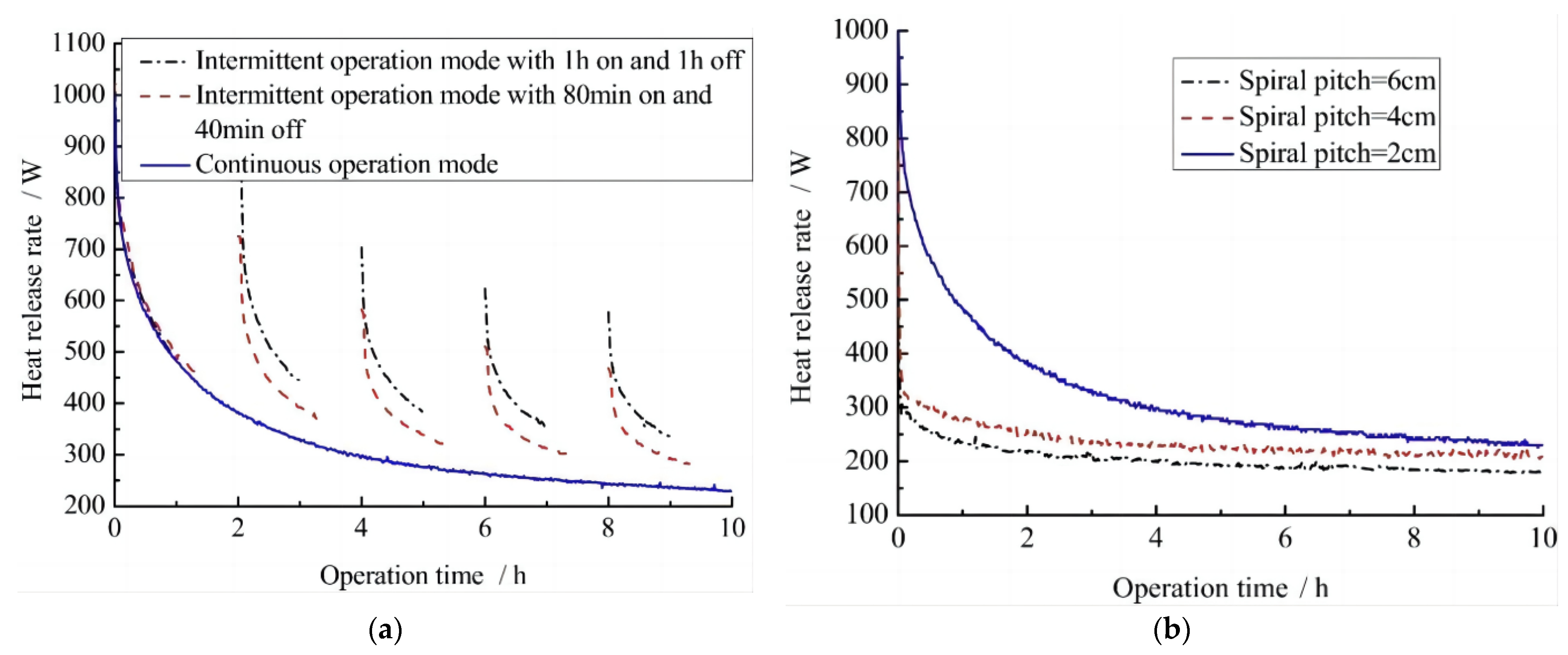
Figure 28 presents the influences of various factors on the heat transfer rate of the spiral-coil energy pile. It is evident that implementing a reasonable intermittent operation mode and reducing the spiral pitch can effectively enhance the heat transfer efficiency of energy piles, leading to improved performance of GSHP systems. Moreover, increasing the inlet water temperature has a positive effect on the heat transfer rate of the heat exchange tube, demonstrating an approximately linear relationship with the inlet water velocity.
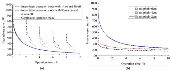
Figure 28.
Influencing factors of heat transfer of spiral-coil energy piles [79]. (a) The effect of operation mode. (b) The effect of spiral pitch.
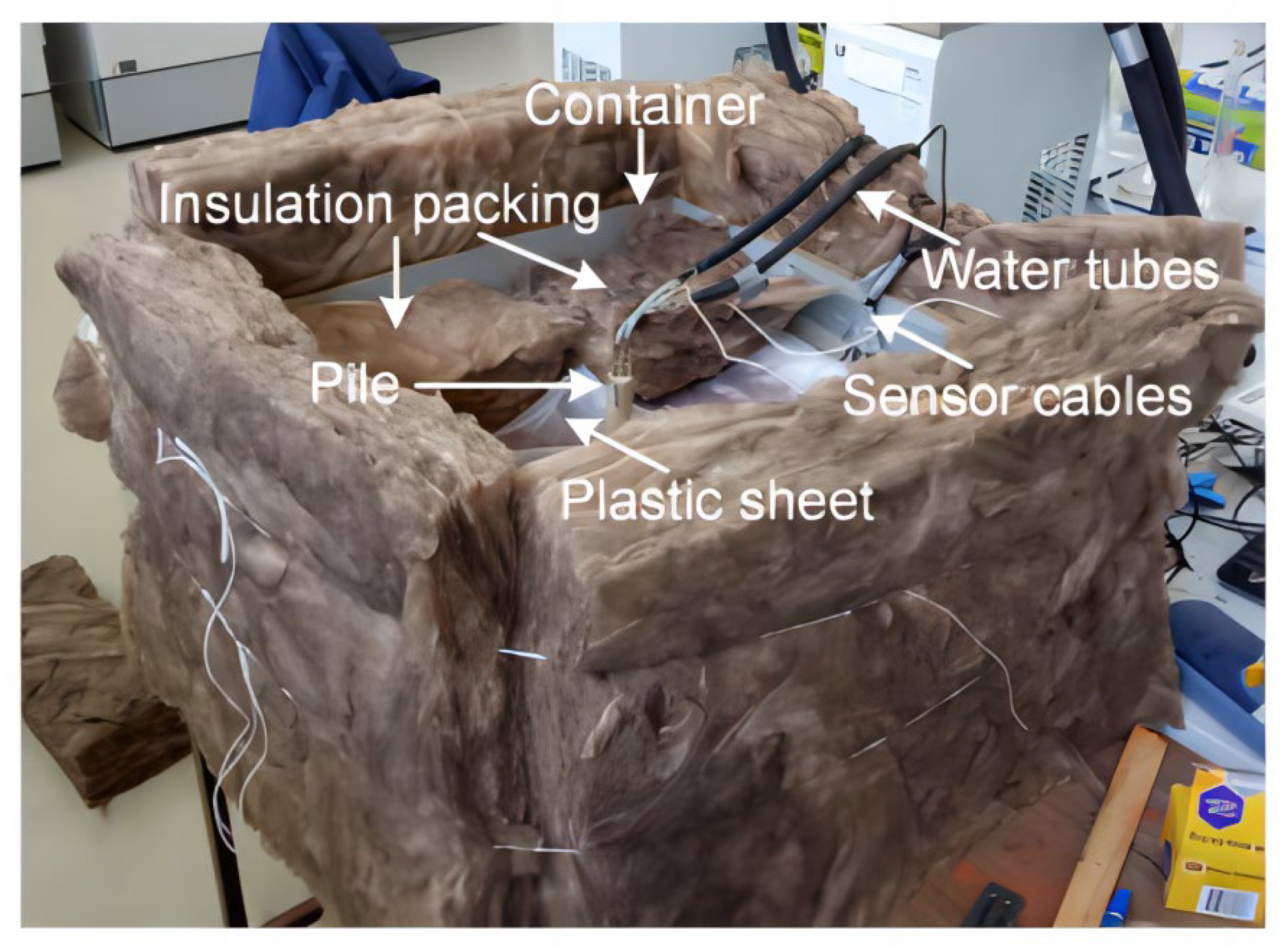
The changes in temperature and moisture content of the soil around the energy pile during the cooling/heating cycles were mainly studied in an energy pile sandbox experiment constructed by Faizal et al. [81], and the layout of the experiment is shown in Figure 29. The rectangular glass sandbox used in the experiment has dimensions of 0.56 × 0.56 × 0.3 m. The energy pile employed in the study has a diameter of 25 mm and a total length of 264 mm. Throughout the experiment, the room temperature was maintained at approximately 20 °C, and the sandbox was designed to be adiabatic, minimizing heat exchange with the surrounding environment.
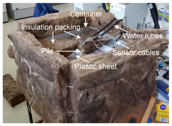
Figure 29.
The sandbox experiment with a rectangular glass sandbox [81].
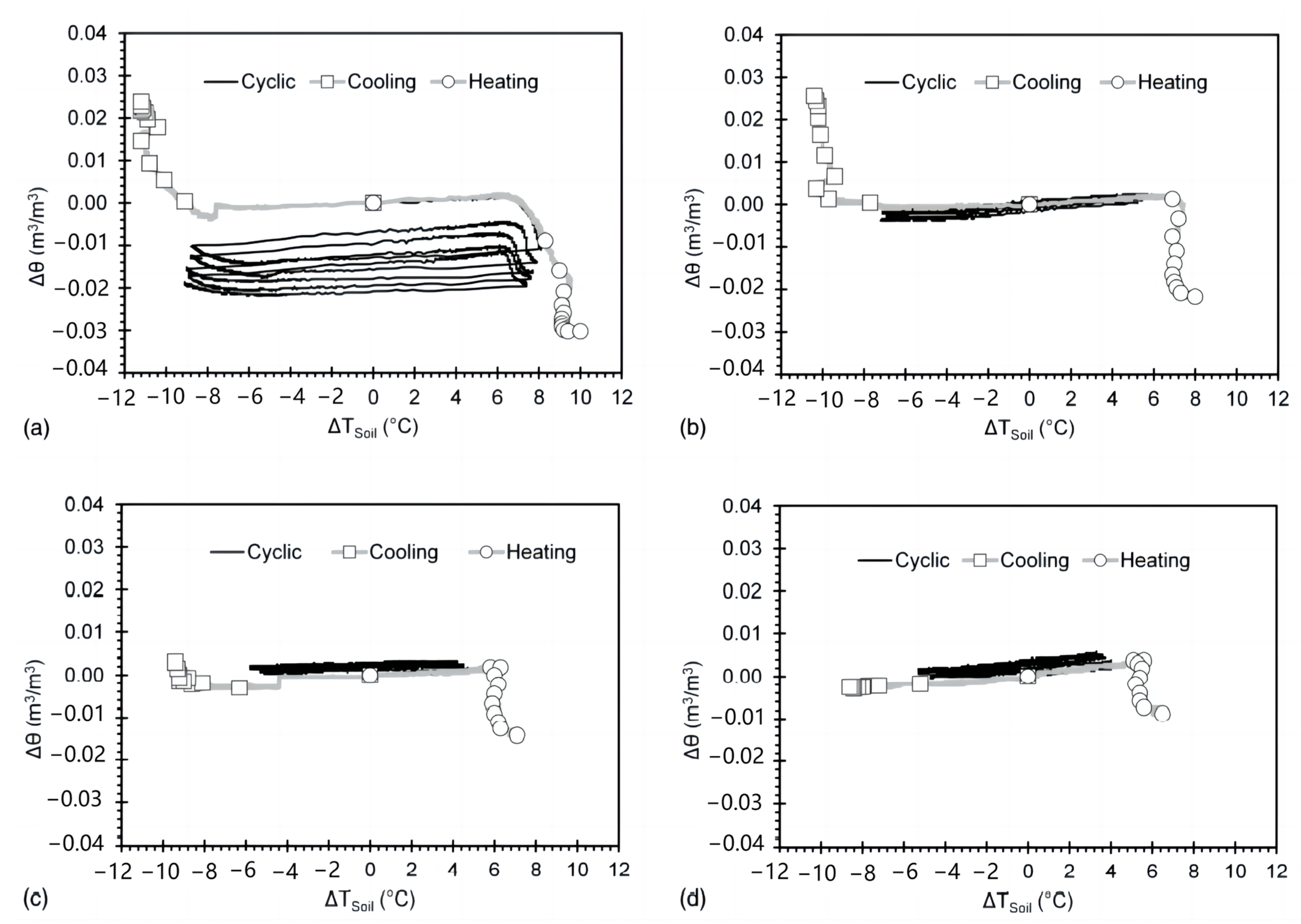
The moisture content and temperature of the soil around the energy pile varies with circulation, as shown in Figure 30. During the heating phase, water moves away from the energy pile, while during the cooling phase, it moves toward the pile. This movement of water results in the drying and wetting of the soil, respectively. In comparison to monotone heating/cooling, cyclic heating/cooling leads to less variability in soil temperature and volumetric water content, which is advantageous for the long-term operation of energy piles. Figure 30a demonstrates the most significant changes in soil temperatures and volumetric water content near the pile, specifically at a radial distance of 20 mm. These changes decrease as the radial distance from the pile increases. Additionally, the volumetric water content adjacent to the pile exhibits a decrease during continuous thermal cycling. During cyclic heating/cooling, the volumetric water content shows an irreversible response to changes in soil temperature, although this response diminishes with increasing radial distance from the pile.
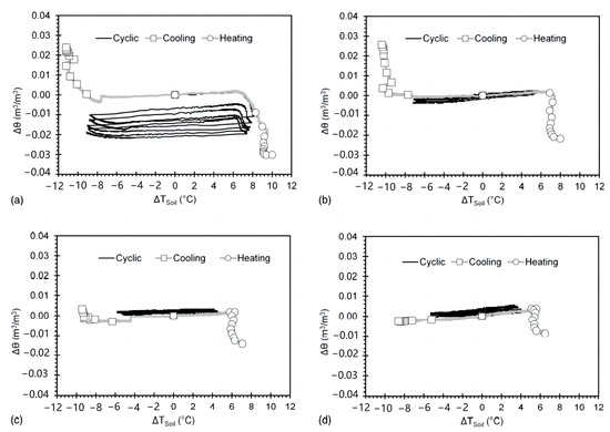
Figure 30.
The changes of volumetric water content (Δθ) and temperature (ΔTSoil) of the soil around the pile at different radiuses: (a) 20 mm; (b) 50 mm; (c) 80 mm; (d) 110 mm [81].
The thermal performance of energy piles is closely related to their arrangement, types, and water flow rates. The research conducted by Kramer et al. [77], Yang et al. [79], and Faizal et al. [81] has revealed the spatial distribution of heat transfer in energy piles, as well as the heat transfer effectiveness of different energy pile types under various operating conditions.
3.3. Thermal-Mechanical Coupled Performance Testing of Energy Piles
The thermal and mechanical performances of energy piles are interconnected during their operation. Therefore, it is crucial to examine the thermal-mechanical coupled performance of energy piles. This investigation should encompass factors such as the type of heat exchange tube and the temperature of the heat medium, which influence the thermal-mechanical coupling. Additionally, studying the temperature distribution in the pile-soil system and the lateral friction distribution between the pile and soil are essential aspects of understanding the thermal-mechanical behavior of energy piles.
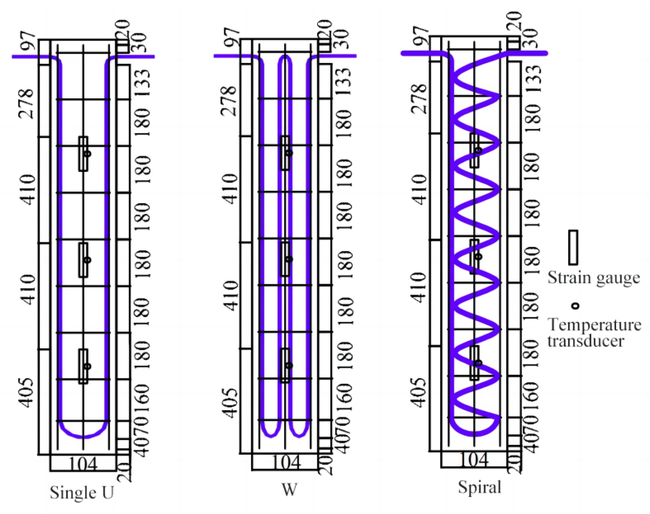
Wang et al. [82] conducted a sandbox experiment to investigate the heat transfer rates and mechanical properties of energy piles using different heat exchange tube configurations, namely single U-shaped, W-shaped, and spiral tubes. The schematic diagrams of the energy piles with these different heat exchange tubes are depicted in Figure 31. The sandbox used in the experiment had dimensions of 3 × 2 × 1.75 m and was placed in a closed environment where the temperature difference was maintained within 2 °C throughout the day. The fluid temperatures during the experiment for heating, indoor air, and cooling conditions were 57 °C, 20 °C, and 5 °C, respectively.
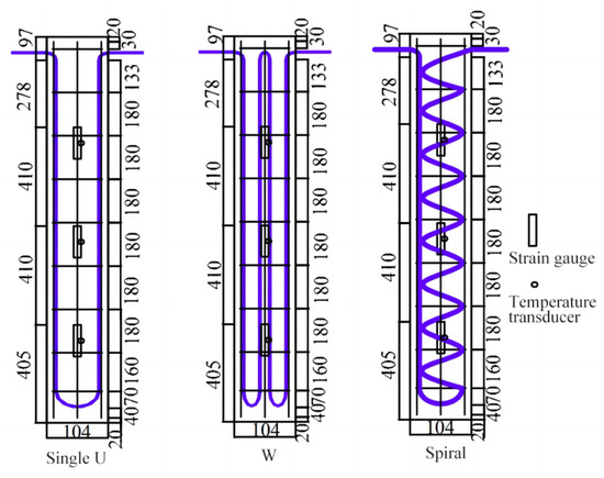
Figure 31.
Energy piles with different tubes (U-shaped, W-shaped, and spiral-coil) [82].
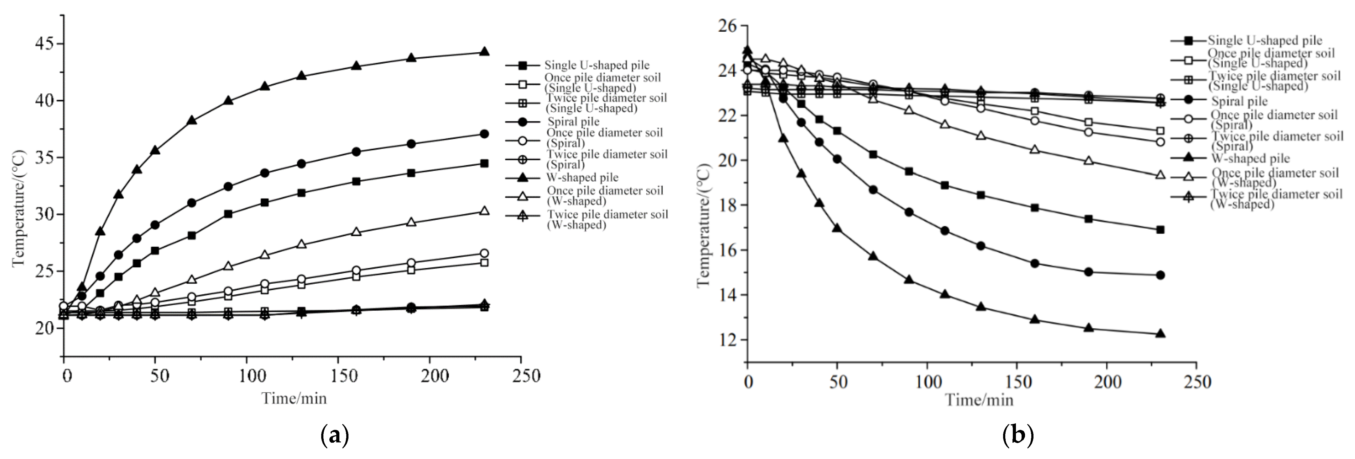
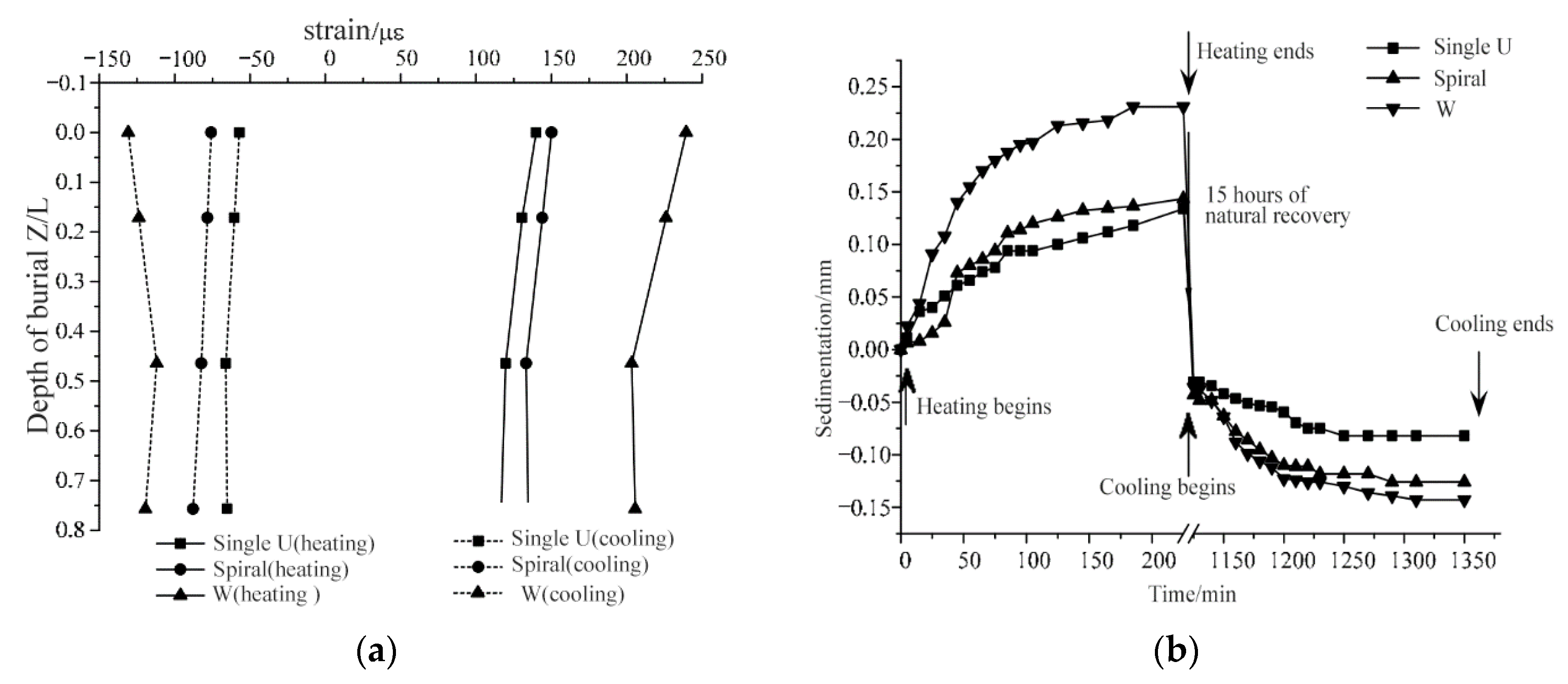
The heat exchange performance and displacement of energy piles exhibit variations depending on the style of tubes used. Figure 32 illustrates the measured heat exchange performance of energy piles with different tube configurations. It is observed that, under heating and cooling conditions, the W-type energy pile exhibits the highest heat exchange rate, while the spiral-type energy pile demonstrates a lower heat exchange rate compared to the W-type energy pile. The single U-shaped energy pile consistently exhibits the lowest heat exchange rate among the three configurations, primarily due to its shorter heat exchange tube. Figure 33 presents the mechanical performances of energy piles with different tube configurations under heating and cooling conditions. It can be seen that, under both heating and cooling conditions, the W-shaped energy pile experiences the largest changes in thermal strain and pile head displacement, while the U-shaped energy pile shows the smallest changes in these parameters.
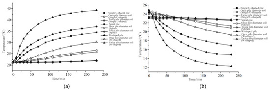
Figure 32.
Pile and soil temperatures of different energy piles [82]. (a) Heating condition. (b) Cooling condition.
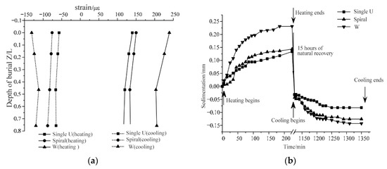
Figure 33.
Comparison of mechanical performances of energy piles with different tubes [82]. (a) Strain change of the pile. (b) Variation of pile top displacement.
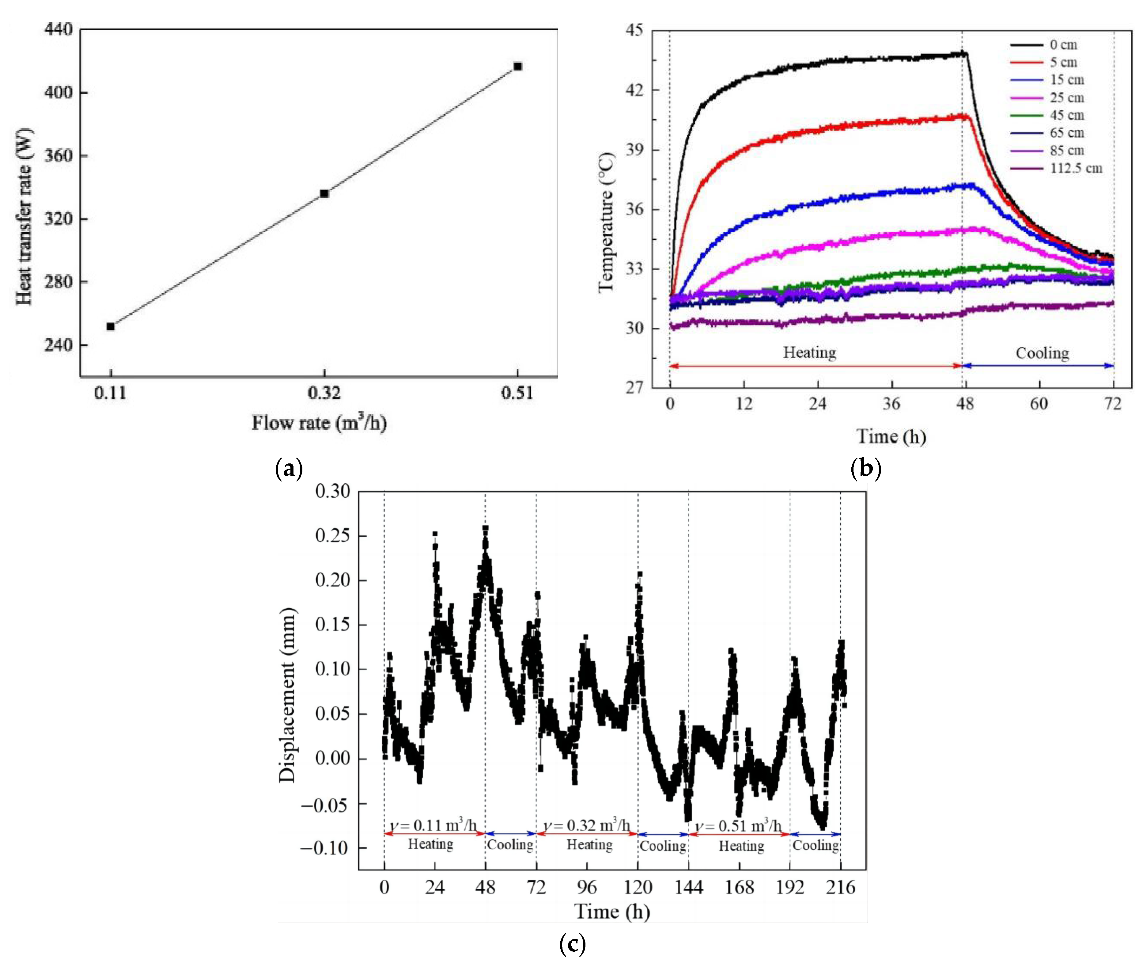
Bao et al. [83] conducted a steel sandbox experiment with dimensions of 2.5 × 2.5 × 2.0 m to investigate the mechanical and thermal performances of energy piles equipped with double U-shaped tubes. The soil in the sandbox was divided into 18 layers, each with a height of 100 mm. To ensure proper contact between the soil layers, they were carefully trimmed. In the experiment, the inlet water temperature was maintained at a constant value of 55 °C. The initial soil temperature and indoor temperature were both set to 31 °C. The thermal cycle consisted of a 48 h heating process at a constant temperature, followed by a 24 h recovery process during which natural cooling occurred. Three thermal cycles were performed in the sandbox, each with a different water flow rate: 0.11 m3/h, 0.32 m3/h, and 0.51 m3/h, respectively.
The heat transfer performance of energy piles is primarily influenced by water flow and the distance from the pile, whereas pile settlement remains essentially unaffected by temperature variations. Figure 34a illustrates the heat transfer rate of the energy pile under different water flow rates. It is observed that as the water flow rate increases, the heat exchange rate of the energy pile improves, indicating a more efficient heat transfer process. Figure 34b presents the variation in soil temperature at different distances from the pile surface. During the heat transfer process, the soil temperature surrounding the pile primarily changes within the first 48 h and subsequently decreases gradually with an increasing distance from the pile. Figure 34c displays the displacement of the pile head observed in this experiment. The displacement demonstrates a declining trend with fluctuations during the thermal cycle, and no clear relationship is evident between the displacement and the temperature.
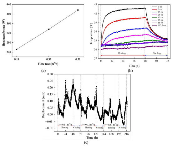
Figure 34.
Thermal and mechanical performance of energy piles [83]. (a) Effect of water flow rate. (b) Soil temperatures. (c) Variation curve of pile head displacement.
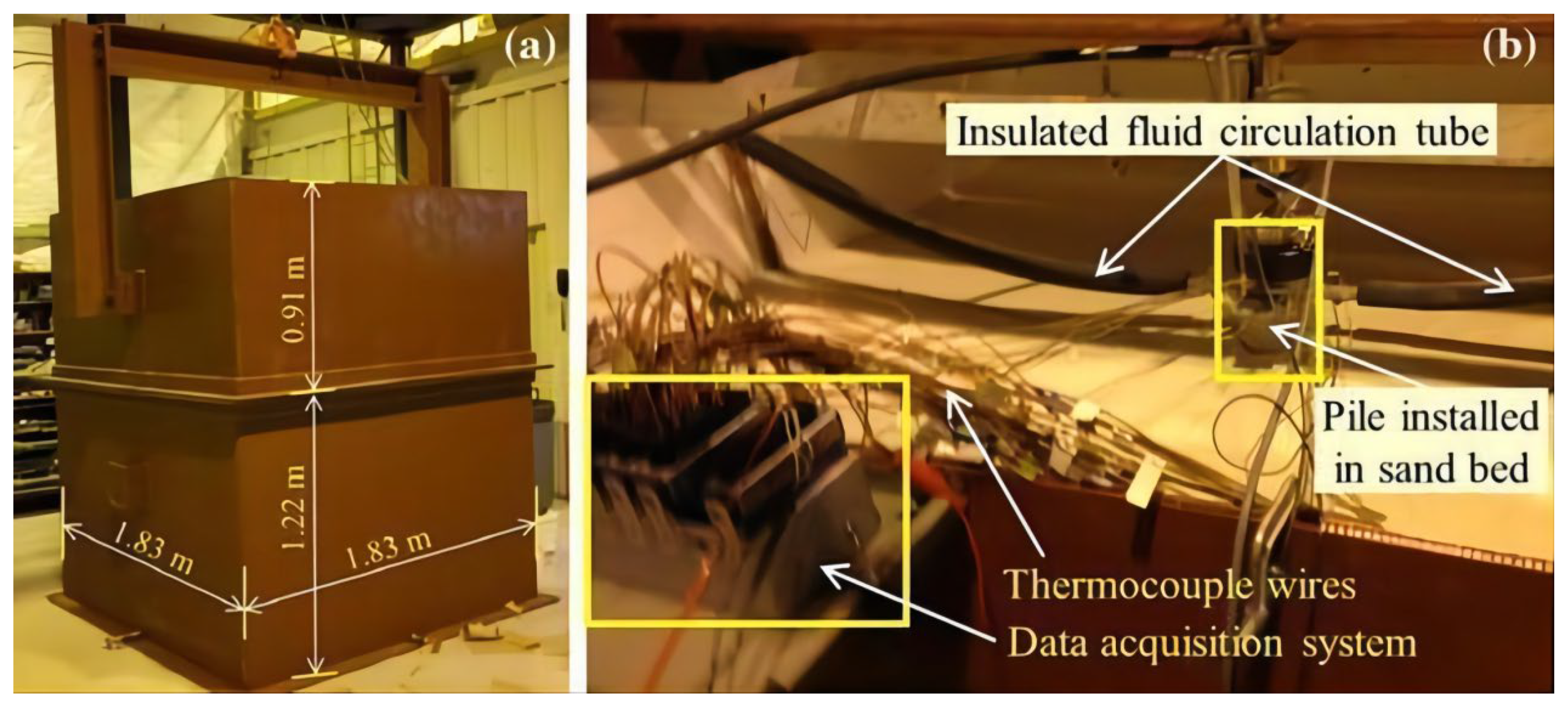
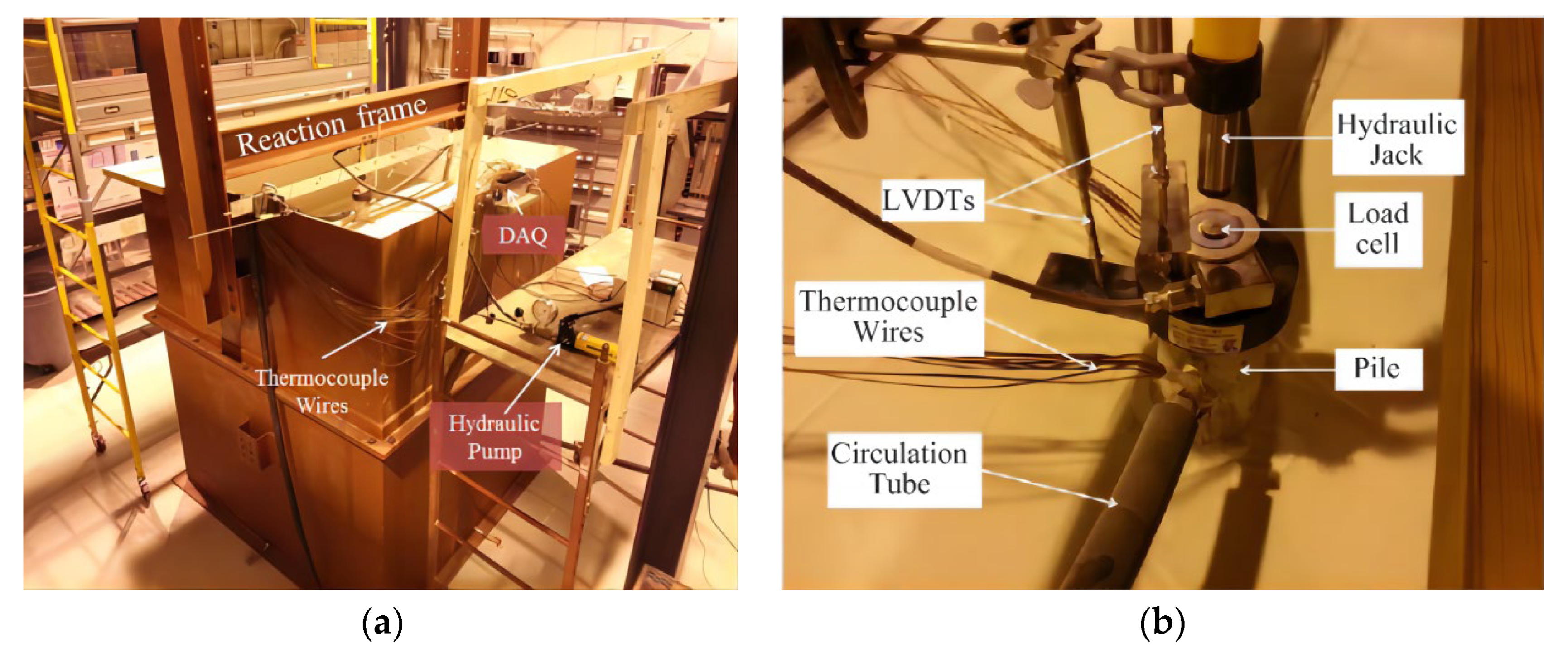
Kramer et al. [84] conducted a single U-shaped energy pile sandbox experiment to investigate the heat transfer properties and mechanical properties of energy piles. The experiment was performed using a steel sandbox with a bottom size of 1.83 × 1.83 m. Figure 35 provides the schematic diagram of the experiment setup, where the sandbox had a total height of 2.13 m and a buried depth of 1.22 m. To ensure uniform sand density, the sand was screened using a sand control device measuring 0.76 × 0.76 m. During the experiment, the load on the pile head was monitored using a load cell with a capacity of 24.5 kN, while the displacement of the pile head and bottom was measured using a Linear Variable Differential Transformer (LVDT). The water flow velocity and inlet temperature were set at 0.135 m/s and 40 °C, respectively. The initial average soil temperature in the sandbox was 19 °C, and thermocouples were used with a sampling interval of 30 s for temperature measurements.
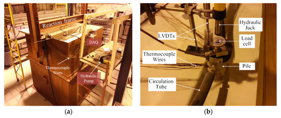
Figure 35.
A single U-shaped energy pile sandbox experiment with a steel sandbox [84]. (a) Steel sandbox. (b) Equipment at the pile head.
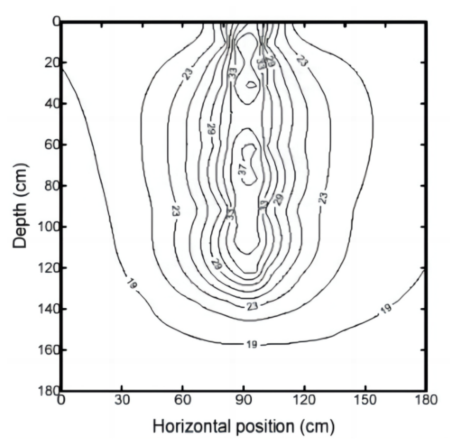
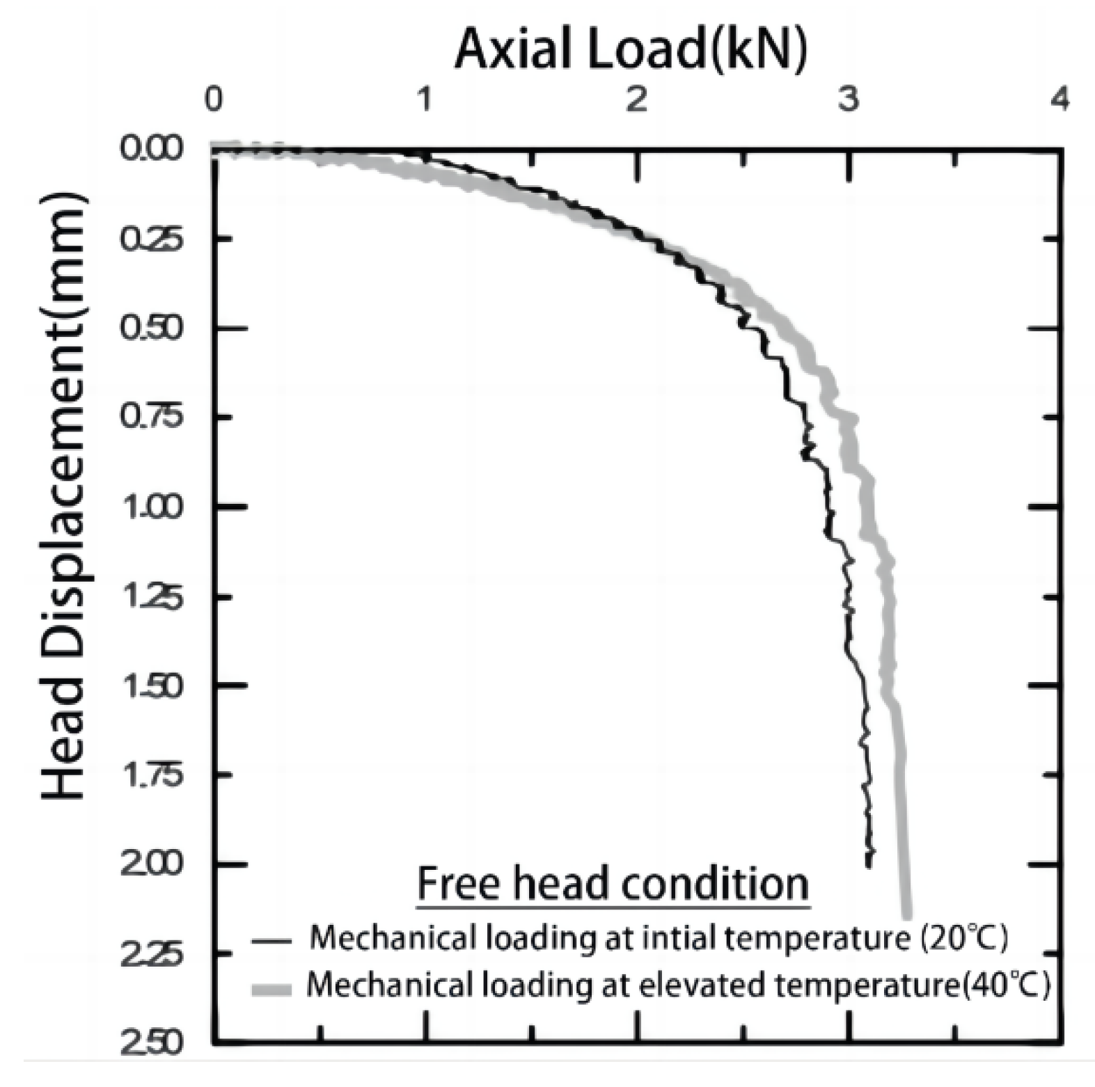
The heat transfer in energy piles exhibits distinct spatial characteristics, as depicted in Figure 36, which illustrates the soil temperature distribution around the pile after seven days of heat transfer. The soil temperature near the energy pile rapidly increases and approaches the water temperature. The heat transfer distance in the radial direction is three times larger than that in the vertical direction. Mechanical load tests were conducted on the energy pile to measure the continuous displacement of the pile head with a load increment of 0.1 kN before and after the heat transfer experiment. Figure 37 illustrates the results, showing a slight increase in the ultimate load of the energy piles after seven days of heat transfer. Additionally, the head stiffness of the pile decreases during the initial stage of load application.
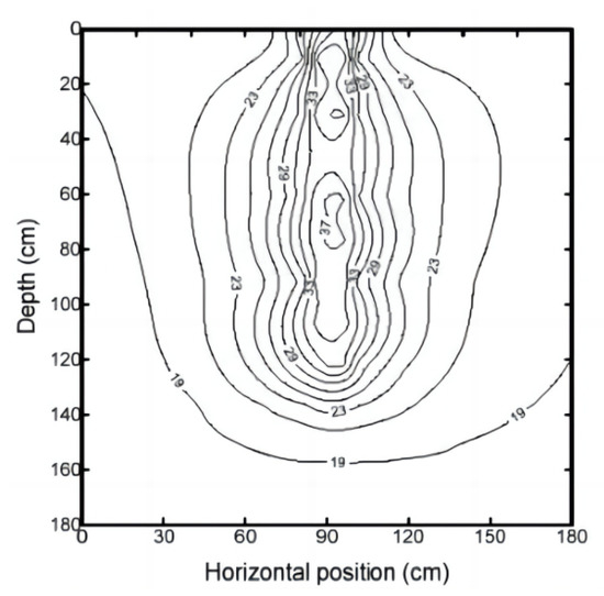
Figure 36.
Soil temperature field around the piles after seven-days’ heat transfer [84].
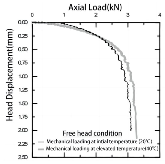
Figure 37.
The relationship between head displacement and axial load of the pile [84].
Wu et al. [85] carried out a sandbox experiment to investigate the heat transfer and displacement behavior of energy piles. In the experiment, the model piles used were constructed using steel tubes with an outer diameter of 23 mm, an inner diameter of 21 mm, and a length of 550 mm. These model piles were buried into the soil, with only 450 mm of their length submerged. At the center of the model pile, a U-shaped copper tube with an inner diameter of 2 mm was placed, and it was connected to a water tank equipped with temperature control. The remaining space within the pile was filled with epoxy resin to ensure stability and integrity. Additionally, a steel plate measuring 100 × 40 × 3 mm was utilized as the pile cap, which was welded to the pile head. This steel plate provided support and reinforcement for the pile structure.
Temperature variations significantly influence the properties of the soil surrounding energy piles, resulting in a positive correlation between water pressure and soil temperature. Figure 38 compares the pile head displacements for single energy piles during heating and cooling, where the pile head displacements are smaller under heating conditions compared to cooling conditions. The adjacent unheated piles form a shielding effect on the energy piles, resulting in the displacement of adjacent piles being smaller than that of a single energy pile. Furthermore, the pile cap restricts the movement of the energy pile, helping to reduce the differential settlement between the energy pile and the adjacent piles.
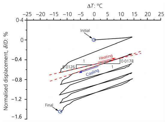
Figure 38.
Comparison of head displacement for the single energy pile under the heating and cooling conditions [85].
The thermal-mechanical coupling sandbox experiments on energy piles have been conducted to explore the interrelationship between the thermal and mechanical performance of energy piles. The current experiments focus on investigating the influence of heat transfer on the displacement, ultimate load capacity, stiffness, and other mechanical properties of energy piles. However, The understanding of the complex interactions between thermal and mechanical behavior in energy piles is still limited. Further research is needed to investigate the coupling mechanisms and the influence of various factors, such as groundwater flow, soil properties, and pile geometry.
3.4. Summary
The aforementioned sandbox experiments focused on studying the mechanical, thermal, and thermo-mechanical performances of energy piles without considering seepage. Regarding the mechanical performance, the settlement of energy piles during thermal cycles increases as the head load of the energy piles grows [56,57], and negative frictional resistance is observed between the soil and energy piles [58]. Concerning thermal characteristics, the heat transfer process of energy piles is approximately axisymmetric, with the soil temperature being higher closer to the energy piles [77,81,84]. The operating conditions and spiral-coil pitch of energy piles [79] are known to impact the heat transfer rate. In terms of thermal-mechanical coupling, experimental results indicate that both soil and pore water pressures increase with higher fluid temperatures inside the tube [83,85]. A comprehensive overview of the research progress on energy-pile sandbox experiments is provided in Table 2, detailing the specific areas of investigation.

Table 2.
Research status on the energy piles sandbox experiment.
4. Summary and Outlook
4.1. Summary
As an energy-efficient and low-carbon technology, GSHP holds significant promise in achieving carbon neutrality within the building sector. One crucial element of GSHP systems is the GHE, which has undergone extensive investigation through sandbox experiments. These experiments serve as an essential approach to studying heat transfer characteristics and validating simulation results. By categorizing existing sandbox experiments, valuable insights can be gained to enhance GHE performance and facilitate the rational development of GSHP systems. The experiments are systematically classified into two categories: borehole sandbox experiments (including single borehole, borehole group, and seepage) and energy pile sandbox experiments (encompassing mechanical performance, thermal performance, and thermal-mechanical coupled performance). A comprehensive summary is provided below:
- (1)
- Briefly, the borehole sandbox experiments can be categorized into single-tube and tube group experiments, with a significant focus on single-tube experiments, particularly those without seepage. Single-tube experiments are straightforward and primarily investigate the impact of heat exchange tube form, circulating water temperature, and flow rate on the borehole’s heat transfer capacity and the distribution of soil temperature. Tube group experiments, on the other hand, typically utilize heating wires or metal tubes with circulating water as heat exchange elements. The use of electric heating wires allows for the emulation of heating and cooling conditions with constant powers, resulting in simple experimental devices and operations. Metal tubes with internal circulating water can replicate the actual internal heat transfer conditions of boreholes, thereby reflecting the influence of circulating water temperature and flow rate on the heat transfer within the borehole group. However, the necessity for a water-circulating system introduces a relatively complex experimental setup. Tube group experiments aim to study the soil temperature distribution around the tube group under constant heat flow and seepage conditions, as well as the impact of heat disturbance from the tube group with known circulating water temperature on the soil temperature field of the tube group without seepage;
- (2)
- Seepage experiments and layered soil experiments are conducted to study the heat transfer effect of boreholes in actual complex environments. Seepage experiments are mainly categorized into vertical seepage and horizontal seepage. In the vertical seepage test, the flow of water in the soil occurs naturally due to gravity, making it a relatively straightforward setup. The horizontal seepage test creates seepage pressure by utilizing a height difference between high and low water tanks. These seepage experiments mainly focus on examining the impact of seepage velocity on the heat transfer of a single tube, the thermal disturbance within the tube group, and the distribution of soil temperature. Those layered soil experiments study the influence of the thermal conductivity of geotechnical materials in different layers on the overall heat transfer;
- (3)
- Energy piles are building pile foundations embedded with heat exchange tubes, of which mechanical performance, thermal performance, and thermal-mechanical coupled performance are the three main research directions. In addition, most of the studies did not consider the seepage factor. Related studies are mainly concerned with sedimentation due to load and thermal cycle. The effect of the heat medium in the tube, the structure of the pile body, and the operating parameters are also discussed to investigate the heat transfer rate and temperature distribution of energy piles under different operation conditions.
4.2. Existing Problems
Although sandbox experiments have been widely conducted, there are several remaining challenges that need to be addressed.
- (1)
- Establishing similarity experiments for practical projects is difficult due to the long depth and small diameter of vertical boreholes. As a result, the experimental data may not accurately depict the heat transfer characteristics of ground heat exchangers (GHEs) in real-world applications;
- (2)
- The measurement accuracy of sandbox experiments is limited. The small size of the sandboxes used in model experiments restricts the heat duty of GHEs and hampers accurate temperature measurements. Consequently, the temperature changes and heat duty obtained from sandbox experiments may not be directly applicable to practical projects;
- (3)
- Controlling the boundary conditions in a sandbox experiment is challenging. Adiabatic boundaries are typically achieved by covering the outer surface of the sandbox with thermal insulation materials, while isothermal boundaries are realized using constant temperature water baths or controlled indoor air temperatures. However, these methods have limitations in precisely maintaining idealized adiabatic and isothermal boundaries;
- (4)
- Soil thermophysical property tests suffer from low accuracy. The sampling process can introduce unavoidable errors as soil thermophysical properties are influenced by soil compactness.
By addressing these challenges and improving the experimental techniques, a more accurate understanding of the heat transfer characteristics and performance of GHEs in practical projects can be achieved.
4.3. Perspectives
The GHE sandbox experiment can not only study the heat transfer mechanism but also verify the heat transfer model. This is significant for the design and application of different types of GHEs under different conditions. Combined with new technologies, there will be more and more studies using GHE sandbox in the future, with some possible aspects as follows:
- (1)
- Complex environmental conditions, such as three-dimensional seepage and multi-layered soil, pose challenges to current seepage experiments. Most current seepage experiments investigate the horizontal seepage process, while there is a lack of seepage experiments for shallow boreholes, including both horizontal seepage and vertical seepage caused by rainfall. Current layered soil experiments are mainly performed with two to three layers of soil, while the multi-layered soil and inclined-layered soil experiments in practical projects have not been considered;
- (2)
- Novel composite energy geostructures: Emerging energy geostructures, such as energy piles, energy walls, and energy tunnels, incorporate heat exchange tubes within building infrastructures, offering the advantage of reducing initial investment costs and occupying less space compared to traditional vertical boreholes. While some types of energy geostructures have been widely adopted globally, current research primarily focuses on vertical boreholes, with a limited investigation into energy geostructures and composite energy geostructures combined with boreholes. Future studies should aim to bridge this research gap and explore the potential of these innovative composite energy geostructures;
- (3)
- The integration of new materials and new technologies presents opportunities for further enhancing the performance of energy geostructures. For example, the use of nanofluids can enhance heat transfer within the heat exchange tubes, while incorporating phase change materials between the heat exchange tube and the soil can mitigate soil temperature variations and improve heat exchange efficiency. To ensure the practical application of these new materials and technologies, relevant sandbox experiments focusing on nanofluids and phase change materials are necessary to verify the feasibility and characterize the performance. These experiments will provide valuable insights into the potential benefits and challenges associated with these advancements.
GSHP technology plays a vital role in improving indoor comfort while striving for carbon neutrality and sustainable development. GHE sandbox experiments will contribute to the wider adoption and popularization of this green technology. This review serves as a valuable reference for the design, construction, and characterization of various sandbox test setups in future research endeavors.
Author Contributions
Conceptualization, T.Y.; Methodology, S.Z.; Investigation, S.Z., L.Z. (Lijie Zhu), R.W. and Y.Z. (Yongzheng Zhang); Data curation, S.Z.; Writing—original draft, S.Z., L.Z. (Lijie Zhu), R.W., T.Z. and Y.Z. (Yi Zhan); Writing—review & editing, F.W., L.Z. (Linfeng Zhang) and T.Y.; Supervision, T.Y.; Project administration, T.Y.; Funding acquisition, T.Y. All authors have read and agreed to the published version of the manuscript.
Funding
This research was funded by the National Natural Science Foundation of China (No. 52108102 and No. 52008088), the Guangdong Basic and Applied Basic Research Foundation (2021A1515011739, 2020A1515110391 and 2020B1515120083), and Sun Yat-Sen University (76140–12220013).
Data Availability Statement
The authors would be willing to share our research data if needed.
Conflicts of Interest
The authors declare no conflict of interest.
References
- Pomianowski, M.; Johra, H.; Marszal-Pomianowska, A.; Zhang, C. Sustainable and energy-efficient domestic hot water systems: A review. Renew. Sustain. Energy Rev. 2020, 128, 109900. [Google Scholar] [CrossRef]
- Wu, W.; Skye, H.M. Residential net-zero energy buildings: Review and perspective. Renew. Sustain. Energy Rev. 2021, 142, 110859. [Google Scholar] [CrossRef]
- Amasyali, K.; El-Gohary, N.M. A review of data-driven building energy consumption prediction studies. Renew. Sustain. Energy Rev. 2018, 81, 1192–1205. [Google Scholar] [CrossRef]
- Soltani, M.; Kashkooli, F.M.; Dehghani-Sanij, A.; Kazemi, A.; Bordbar, N.; Farshchi, M.; Elmi, M.; Gharali, K.; Dusseault, M.B. A comprehensive study of geothermal heating and cooling systems. Sustain. Cities Soc. 2019, 44, 793–818. [Google Scholar] [CrossRef]
- Li, B.; Hu, P.; Zhu, N.; Lei, F.; Xing, L. Performance analysis and optimization of a CCHP-GSHP coupling system based on quantum genetic algorithm. Sustain. Cities Soc. 2019, 46, 101408. [Google Scholar] [CrossRef]
- Yang, W.; Ju, L.; Zhang, L.; Wang, F. Experimental investigations of the thermo-mechanical behaviour of an energy pile with groundwater seepage. Sustain. Cities Soc. 2022, 77, 103588. [Google Scholar] [CrossRef]
- Mui, K.; Tsang, T.W.; Wong, L. Bayesian updates for indoor thermal comfort models. J. Build. Eng. 2020, 29, 101117. [Google Scholar] [CrossRef]
- Cao, X.; Dai, X.; Liu, J. Building energy-consumption status worldwide and the state-of-the-art technologies for zero-energy buildings during the past decade. Energy Build. 2016, 128, 198–213. [Google Scholar] [CrossRef]
- Yang, L.; Yan, H.; Lam, J.C. Thermal comfort and building energy consumption implications–a review. Appl. Energy 2014, 115, 164–173. [Google Scholar] [CrossRef]
- Kwong, Q.J.; Adam, N.M.; Sahari, B. Thermal comfort assessment and potential for energy efficiency enhancement in modern tropical buildings: A review. Energy Build. 2014, 68, 547–557. [Google Scholar] [CrossRef]
- Spitler, J.D.; Gehlin, S.E. Thermal response testing for ground source heat pump systems—An historical review. Renew. Sustain. Energy Rev. 2015, 50, 1125–1137. [Google Scholar] [CrossRef]
- Self, S.J.; Reddy, B.V.; Rosen, M.A. Geothermal heat pump systems: Status review and comparison with other heating options. Appl. Energy 2013, 101, 341–348. [Google Scholar] [CrossRef]
- Liang, B.; Chen, M.; Orooji, Y. Effective parameters on the performance of ground heat exchangers: A review of latest advances. Geothermics 2022, 98, 102283. [Google Scholar] [CrossRef]
- Menegazzo, D.; Lombardo, G.; Bobbo, S.; De Carli, M.; Fedele, L. State of the art, perspective and obstacles of ground-source heat pump technology in the European building sector: A review. Energies 2022, 15, 2685. [Google Scholar] [CrossRef]
- Karytsas, S.; Choropanitis, I. Barriers against and actions towards renewable energy technologies diffusion: A Principal Component Analysis for residential ground source heat pump (GSHP) systems. Renew. Sustain. Energy Rev. 2017, 78, 252–271. [Google Scholar] [CrossRef]
- Omer, A.M. Ground-source heat pumps systems and applications. Renew. Sustain. Energy Rev. 2008, 12, 344–371. [Google Scholar] [CrossRef]
- Sanner, B.; Karytsas, C.; Mendrinos, D.; Rybach, L. Current status of ground source heat pumps and underground thermal energy storage in Europe. Geothermics 2003, 32, 579–588. [Google Scholar] [CrossRef]
- Fang, L.; Diao, N.; Shao, Z.; Zhu, K.; Fang, Z. A computationally efficient numerical model for heat transfer simulation of deep borehole heat exchangers. Energy Build. 2018, 167, 79–88. [Google Scholar] [CrossRef]
- You, T.; Wu, W.; Yang, H.; Liu, J.; Li, X. Hybrid photovoltaic/thermal and ground source heat pump: Review and perspective. Renew. Sustain. Energy Rev. 2021, 151, 111569. [Google Scholar] [CrossRef]
- Cui, Y.; Zhu, J.; Twaha, S.; Chu, J.; Bai, H.; Huang, K.; Chen, X.; Zoras, S.; Soleimani, Z. Techno-economic assessment of the horizontal geothermal heat pump systems: A comprehensive review. Energy Convers. Manag. 2019, 191, 208–236. [Google Scholar] [CrossRef]
- Sarbu, I.; Sebarchievici, C. General review of ground-source heat pump systems for heating and cooling of buildings. Energy Build. 2014, 70, 441–454. [Google Scholar] [CrossRef]
- Luo, J.; Rohn, J.; Xiang, W.; Bertermann, D.; Blum, P. A review of ground investigations for ground source heat pump (GSHP) systems. Energy Build. 2016, 117, 160–175. [Google Scholar] [CrossRef]
- Gaur, A.S.; Fitiwi, D.Z.; Curtis, J. Heat pumps and our low-carbon future: A comprehensive review. Energy Res. Soc. Sci. 2021, 71, 101764. [Google Scholar] [CrossRef]
- Boban, L.; Miše, D.; Herceg, S.; Soldo, V. Application and design aspects of ground heat exchangers. Energies 2021, 14, 2134. [Google Scholar] [CrossRef]
- Estrada, E.; Labat, M.; Lorente, S.; Rocha, L.A. The impact of latent heat exchanges on the design of earth air heat exchangers. Appl. Therm. Eng. 2018, 129, 306–317. [Google Scholar] [CrossRef]
- Aresti, L.; Christodoulides, P.; Florides, G. A review of the design aspects of ground heat exchangers. Renew. Sustain. Energy Rev. 2018, 92, 757–773. [Google Scholar] [CrossRef]
- Yuan, Y.; Cao, X.; Sun, L.; Lei, B.; Yu, N. Ground source heat pump system: A review of simulation in China. Renew. Sustain. Energy Rev. 2012, 16, 6814–6822. [Google Scholar] [CrossRef]
- Yuan, Y.; Lei, B.; Yu, N.; Cao, X. Heat transfer of ground heat exchanger for GSHP (1): A review. Heat. Vent. Air Cond. 2008, 38, 25–32. [Google Scholar]
- Aranzabal, N.; Martos, J.; Steger, H.; Blum, P.; Soret, J. Temperature measurements along a vertical borehole heat exchanger: A method comparison. Renew. Energy 2019, 143, 1247–1258. [Google Scholar] [CrossRef]
- Spitler, J.; Bernier, M. Vertical borehole ground heat exchanger design methods. In Advances in Ground-Source Heat Pump Systems; Elsevier: Amsterdam, The Netherlands, 2016; pp. 29–61. [Google Scholar]
- Liu, X.; Spitler, J.D.; Qu, M.; Shi, L. Recent developments in the design of vertical borehole ground heat exchangers for cost reduction and thermal energy storage. J. Energy Resour. Technol. 2021, 143, 100803. [Google Scholar] [CrossRef]
- Rammal, D.; Mroueh, H.; Burlon, S. Impact of thermal solicitations on the design of energy piles. Renew. Sustain. Energy Rev. 2018, 92, 111–120. [Google Scholar] [CrossRef]
- Mohamad, Z.; Fardoun, F.; Meftah, F. A review on energy piles design, evaluation, and optimization. J. Clean. Prod. 2021, 292, 125802. [Google Scholar] [CrossRef]
- Cunha, R.; Bourne-Webb, P. A critical review on the current knowledge of geothermal energy piles to sustainably climatize buildings. Renew. Sustain. Energy Rev. 2022, 158, 112072. [Google Scholar] [CrossRef]
- Rotta Loria, A.; Laloui, L. Thermally induced group effects among energy piles. Géotechnique 2017, 67, 374–393. [Google Scholar] [CrossRef]
- Li, M.; Lai, A.C. Review of analytical models for heat transfer by vertical ground heat exchangers (GHEs): A perspective of time and space scales. Appl. Energy 2015, 151, 178–191. [Google Scholar] [CrossRef]
- Li, C.; Guan, Y.; Jiang, C.; Deng, S.; Lu, Z. Numerical study on the heat transfer, extraction, and storage in a deep-buried pipe. Renew. Energy 2020, 152, 1055–1066. [Google Scholar] [CrossRef]
- Zhu, L.; Chen, S.; Yang, Y.; Sun, Y. Transient heat transfer performance of a vertical double U-tube borehole heat exchanger under different operation conditions. Renew. Energy 2019, 131, 494–505. [Google Scholar] [CrossRef]
- Ma, Z.; Kong, Q.; Xu, K.; Wang, P.; Liu, S.; Jin, L. Numerical simulation on heat transfer inside and outside of vertical buried pipes based on two-model order reduction methods. Numer. Heat Transf. Part A Appl. 2021, 79, 631–655. [Google Scholar] [CrossRef]
- Saeidi, R.; Noorollahi, Y.; Esfahanian, V. Numerical simulation of a novel spiral type ground heat exchanger for enhancing heat transfer performance of geothermal heat pump. Energy Convers. Manag. 2018, 168, 296–307. [Google Scholar] [CrossRef]
- Guan, Y.; Zhao, X.; Wang, G.; Dai, J.; Zhang, H. 3D dynamic numerical programming and calculation of vertical buried tube heat exchanger performance of ground-source heat pumps under coupled heat transfer inside and outside of tube. Energy Build. 2017, 139, 186–196. [Google Scholar] [CrossRef]
- Li, C.; Jiang, C.; Guan, Y.; Tan, Z.; Zhao, Z.; Zhou, Y. Development and applicability of heat transfer analytical model for coaxial-type deep-buried pipes. Energy 2022, 255, 124533. [Google Scholar] [CrossRef]
- Li, M.; Lai, A.C.K. Analytical model for short-time responses of ground heat exchangers with U-shaped tubes: Model development and validation. Appl. Energy 2013, 104, 510–516. [Google Scholar] [CrossRef]
- Li, C.; Jiang, C.; Guan, Y. An analytical model for heat transfer characteristics of a deep-buried U-bend pipe and its heat transfer performance under different deflecting angles. Energy 2022, 244, 122682. [Google Scholar] [CrossRef]
- Huang, X.; Yao, Z.; Cai, H.; Li, X.; Chen, H. Performance evaluation of coaxial borehole heat exchangers considering ground non-uniformity based on analytical solutions. Int. J. Therm. Sci. 2021, 170, 107162. [Google Scholar] [CrossRef]
- Cui, P.; Li, X.; Man, Y.; Fang, Z. Heat transfer analysis of pile geothermal heat exchangers with spiral coils. Appl. Energy 2011, 88, 4113–4119. [Google Scholar] [CrossRef]
- Wang, P. Research on the Double-Spiral Heat Exchanger in Ground Heat. Master’s Thesis, Southwest Jiaotong University, Chengdu, China, 2012. (In Chinese). [Google Scholar]
- Diao, N. Heat Transfer Analyses of Ground Heat Exchangers and Their Engineering Applications. Ph.D. Thesis, Tsinghua University, Beijing, China, 2005. (In Chinese). [Google Scholar]
- Xu, B.; Zhang, H.; Chen, Z. Study on heat transfer performance of geothermal pile-foundation heat exchanger with 3-U pipe configuration. Int. J. Heat Mass Transf. 2020, 147, 119020. [Google Scholar] [CrossRef]
- Tian, X.; Mao, R.; Pei, P. Experimental study on temperature control optimization of ground source heat pump horizontal headers. Energy Build. 2022, 277, 112541. [Google Scholar] [CrossRef]
- Amatya, B.L.; Soga, K.; Bourne-Webb, P.J.; Amis, T.; Laloui, L. Thermo-mechanical behaviour of energy piles. Géotechnique 2012, 62, 503–519. [Google Scholar] [CrossRef]
- Chen, Z.; Yao, J.; Pan, P.; Xiao, H.; Ma, Q. Research on the heat exchange characteristics of the deeply buried pipe type of energy pile. Case Stud. Therm. Eng. 2021, 27, 101268. [Google Scholar] [CrossRef]
- Mimouni, T.; Laloui, L. Behaviour of a group of energy piles. Can. Geotech. J. 2015, 52, 1913–1929. [Google Scholar] [CrossRef]
- You, S.; Cheng, X.; Yu, C.; Dang, Z. Effects of groundwater flow on the heat transfer performance of energy piles: Experimental and numerical analysis. Energy Build. 2017, 155, 249–259. [Google Scholar] [CrossRef]
- Lee, S.; Park, S.; Ahn, D.; Choi, H. Thermal performance of novel cast-in-place energy piles equipped with multipurpose steel pipe heat exchangers (SPHXs). Geothermics 2022, 102, 102389. [Google Scholar] [CrossRef]
- Nguyen, V.T.; Tang, A.M.; Pereira, J.-M. Long-term thermo-mechanical behavior of energy pile in dry sand. Acta Geotech. 2017, 12, 729–737. [Google Scholar] [CrossRef]
- Kalantidou, A.; Tang, A.; Pereira, J.-M.; Hassen, G. Preliminary study on the mechanical behaviour of heat exchanger pile in physical model. Géotechnique 2012, 62, 1047–1051. [Google Scholar] [CrossRef]
- Qian, F.; Liu, G.; Tang, Y.; Xiong, Y.; Fan, G.; Qi, C.; Zhen, M. Study on energy pile-soil mechanical characteristics under cyclic temperature and load. Build. Struct. 2020, 50, 136–142. [Google Scholar]
- Zhang, L. Theoretical and Experimental Explorations on Heat Transfer Performance of Vertical Ground Heat Exchanger in Soils with Groundwater Advection. Ph.D. Thesis, Xi’an University of Architecture and Technology, Xi’an, China, 2016. [Google Scholar]
- Liu, F. Experimental Study on Temperature Filed of Underground Heat Exchanger of Ground-Coupled Heat Pump. Master’s Thesis, Harbin Institute of Technology, Harbin, China, 2008. [Google Scholar]
- Wang, W. Heat Transfer Performance and Heat Transfer Efficiency of Vertical Ground Heat Exchanger in Layered Subsurface. Ph.D. Thesis, China University of Geosciences, Wuhan, China, 2019. [Google Scholar]
- You, T.; Wang, B.; Li, X.; Shi, W.; Yang, H. A general distributed parameter model for ground heat exchangers with arbitrary shape and type of heat sources. Energy Convers. Manag. 2018, 164, 667–679. [Google Scholar] [CrossRef]
- Du, R.; Jiang, D.; Wang, Y.; Shah, K.W. An experimental investigation of CuO/water nanofluid heat transfer in geothermal heat exchanger. Energy Build. 2020, 227, 110402. [Google Scholar] [CrossRef]
- Li, W.; Li, X.; Du, R.; Wang, Y.; Tu, J. Experimental investigations of the heat load effect on heat transfer of ground heat exchangers in a layered subsurface. Geothermics 2019, 77, 75–82. [Google Scholar] [CrossRef]
- Li, C.; Guan, Y.; Wang, X.; Zhou, C.; Xun, Y.; Gui, L. Experimental and numerical studies on heat transfer characteristics of vertical deep-buried U-bend pipe in intermittent heating mode. Geothermics 2019, 79, 14–25. [Google Scholar] [CrossRef]
- Chen, J.; Xia, L.; Li, B.; Mmereki, D. Simulation and experimental analysis of optimal buried depth of the vertical U-tube ground heat exchanger for a ground-coupled heat pump system. Renew. Energy 2015, 73, 46–54. [Google Scholar] [CrossRef]
- Aydın, M.; Sisman, A. Experimental and computational investigation of multi U-tube boreholes. Appl. Energy 2015, 145, 163–171. [Google Scholar] [CrossRef]
- Jia, Y.; Wang, Y. Comparative analyses on 2D and 3D buried tube-group heat transfer models in GCHP system. J. Grad. Univ. Chin. Acad. Sci. 2013, 30, 311–316. [Google Scholar]
- Beier, R.A.; Smith, M.D.; Spitler, J.D. Reference data sets for vertical borehole ground heat exchanger models and thermal response test analysis. Geothermics 2011, 40, 79–85. [Google Scholar] [CrossRef]
- You, T.; Li, X.; Cao, S.; Yang, H. Soil thermal imbalance of ground source heat pump systems with spiral-coil energy pile groups under seepage conditions and various influential factors. Energy Convers. Manag. 2018, 178, 123–136. [Google Scholar] [CrossRef]
- Li, L. Experimental Study of Heat Transfer Process of Vertical U Type Buried Pipe under Seepage Condition. Master’s Thesis, Taiyuan University of Technology, Taiyuan, China, 2017. (In Chinese). [Google Scholar]
- Wang, R.; Yang, C.; Ni, L.; Yao, Y. Experimental study on heat transfer of soil with different moisture contents and seepage for ground source heat pump. Indoor Built Environ. 2020, 29, 1238–1248. [Google Scholar] [CrossRef]
- Sani, A.; Singh, R.; Amis, T.; Cavarretta, I. A review on the performance of geothermal energy pile foundation, its design process and applications. Renew. Sustain. Energy Rev. 2019, 106, 54–78. [Google Scholar] [CrossRef]
- Jiang, Q.; Jiao, Y.; Luo, J.; Wang, H. Review and prospect on heat transfer and bearing performance of energy piles. Rock Soil Mech. 2019, 40, 3351–3362. [Google Scholar]
- Li, Q.; Chen, L.; Ma, H.; Huang, C.-H. Enhanced heat transfer characteristics of graphite concrete and its application in energy piles. Adv. Mater. Sci. Eng. 2018, 2018, 8142392. [Google Scholar] [CrossRef]
- Kong, L.-P.; Qiao, L.; Xiao, Y.-Y.; Li, Q.-W. A study on heat transfer characteristics and pile group influence of enhanced heat transfer energy piles. J. Build. Eng. 2019, 24, 100768. [Google Scholar] [CrossRef]
- Kramer, C.A.; Ghasemi-Fare, O.; Basu, P. Laboratory thermal performance tests on a model heat exchanger pile in sand. Geotech. Geol. Eng. 2015, 33, 253–271. [Google Scholar] [CrossRef]
- Cui, H.; Zou, H.; Bao, X.; Qi, X.; Qi, H. Heat exchange behavior of the phase change energy pile under cooling condition. J. Tsinghua Univ. (Sci. Technol.) 2020, 60, 715–725. [Google Scholar]
- Yang, W.; Lu, P.; Chen, Y. Laboratory investigations of the thermal performance of an energy pile with spiral coil ground heat exchanger. Energy Build. 2016, 128, 491–502. [Google Scholar] [CrossRef]
- Liu, H.; Huang, X.; Kong, G.; Peng, H.; Che, P. Influence of pile core medium on heat transfer efficiency of tubular energy pile. China J. Highw. Transp. 2019, 32, 1–11. [Google Scholar]
- Faizal, M.; Bouazza, A.; McCartney, J.S. Thermohydraulic responses of unsaturated sand around a model energy pile. J. Geotech. Geoenvironmental Eng. 2021, 147, 04021105. [Google Scholar] [CrossRef]
- Wang, C.; Liu, H.; Kong, G.; Wu, D. Model tests on thermal mechanical behavior of energy piles influenced with heat exchangers types. Eng. Mech. 2017, 34, 85–91. [Google Scholar]
- Bao, X.; Li, Y.; Feng, T.; Cui, H.; Chen, X. Investigation on thermo-mechanical behavior of reinforced concrete energy pile with large cross-section in saturated sandy soil by model experiments. Undergr. Space 2020, 5, 229–241. [Google Scholar] [CrossRef]
- Kramer, C.A.; Basu, P. Performance of a model geothermal pile in sand. In Proceedings of the 8th International Conference on Physical Modelling in Geotechnics 2014 (ICPMG), Perth, Australia, 14–17 January 2014; CRC Press/Balkema: Leiden, The Nethersland, 2014; pp. 771–777. [Google Scholar]
- Wu, D.; Liu, H.; Kong, G.; Ng, C.W.W.; Cheng, X.-H. Displacement response of an energy pile in saturated clay. Proc. Inst. Civ. Eng.-Geotech. Eng. 2018, 171, 285–294. [Google Scholar] [CrossRef]
Disclaimer/Publisher’s Note: The statements, opinions and data contained in all publications are solely those of the individual author(s) and contributor(s) and not of MDPI and/or the editor(s). MDPI and/or the editor(s) disclaim responsibility for any injury to people or property resulting from any ideas, methods, instructions or products referred to in the content. |
© 2023 by the authors. Licensee MDPI, Basel, Switzerland. This article is an open access article distributed under the terms and conditions of the Creative Commons Attribution (CC BY) license (https://creativecommons.org/licenses/by/4.0/).

