
Novel Proton Exchange Membranes Based on Sulfonated Poly(acrylonitrile-co-glycidyl methacrylate)/Poly(vinyl chloride) Composite
 , , and
Abstract
:1. Introduction
2. Materials and Methods
2.1. Materials
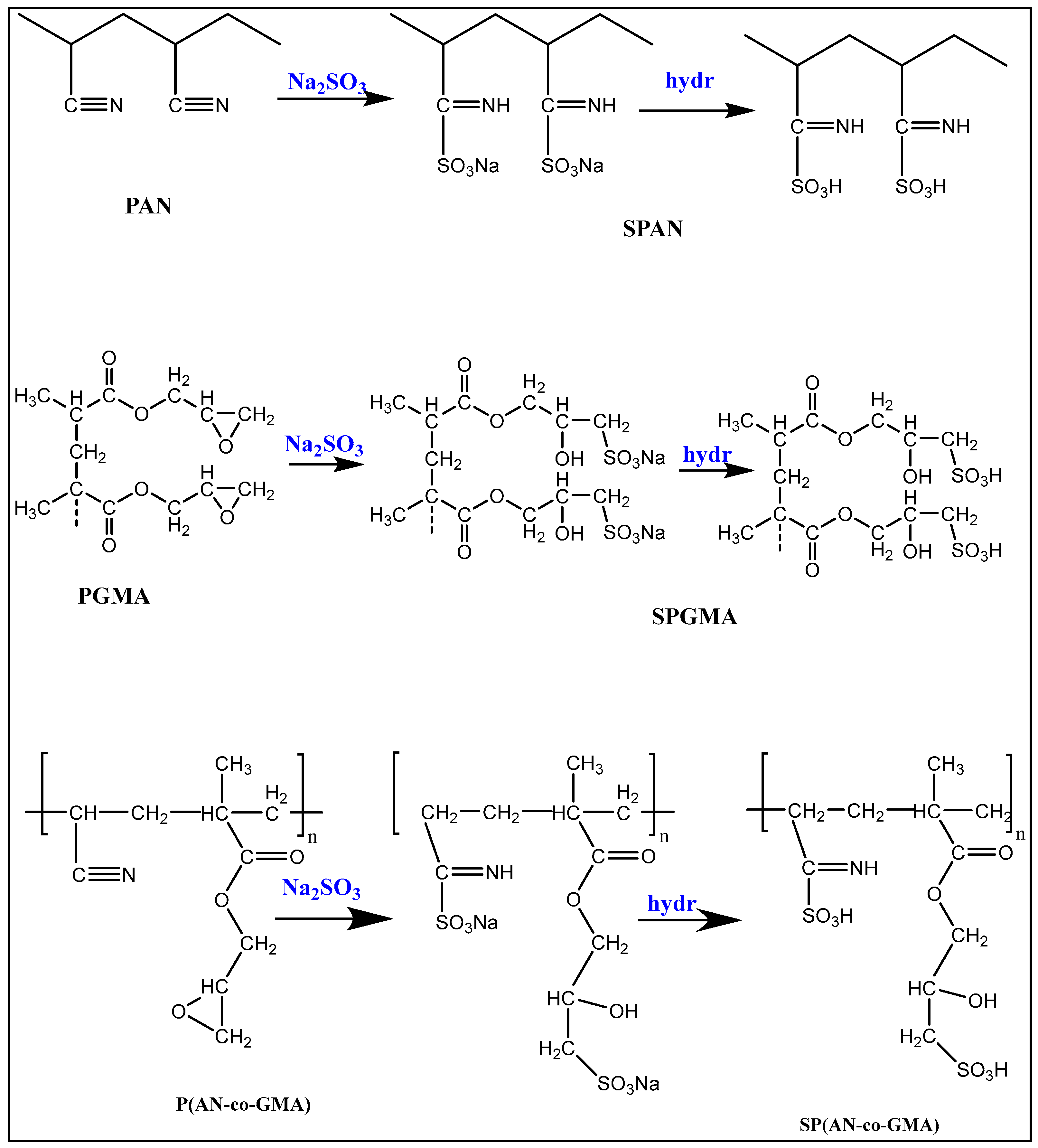
2.2. Preparation of Homo- and Co-Polymers
2.3. Sulfonation of Homo- and Co-Polymers
2.4. Preparation of Polyelectrolyte Membranes (PEMs)
2.5. Characterization
2.5.1. Structural Properties
2.5.2. Thermal Stability
2.5.3. Mechanical Strength
2.5.4. Morphological Features
2.5.5. Surface Roughness
2.5.6. Wettability
2.5.7. Ion Exchange Capacity
2.5.8. Water and Methanol Uptake
2.5.9. Methanol Permeability
3. Results and Discussion
3.1. Structural Properties
3.1.1. FTIR Spectra
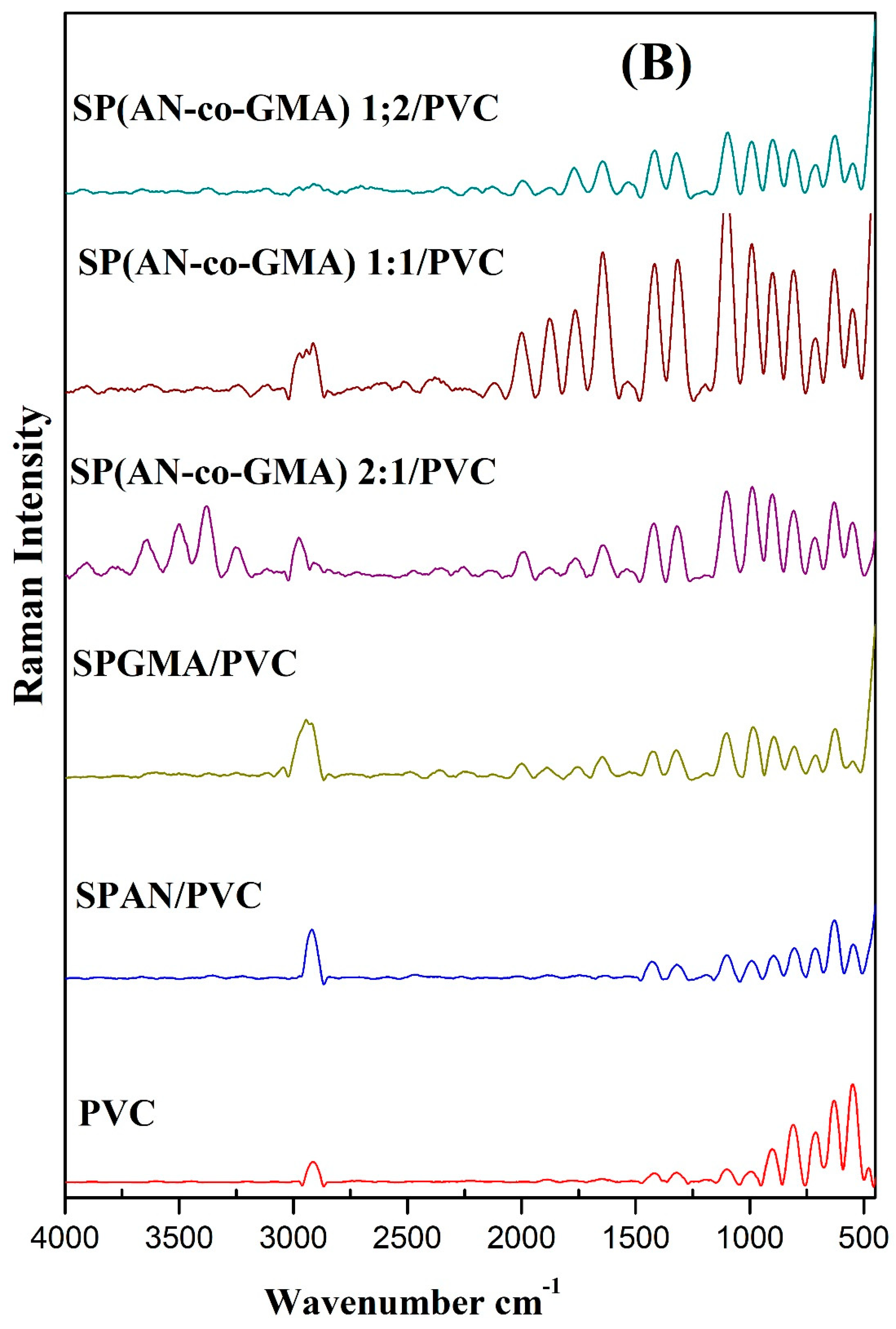
3.1.2. Raman Scattering Spectra
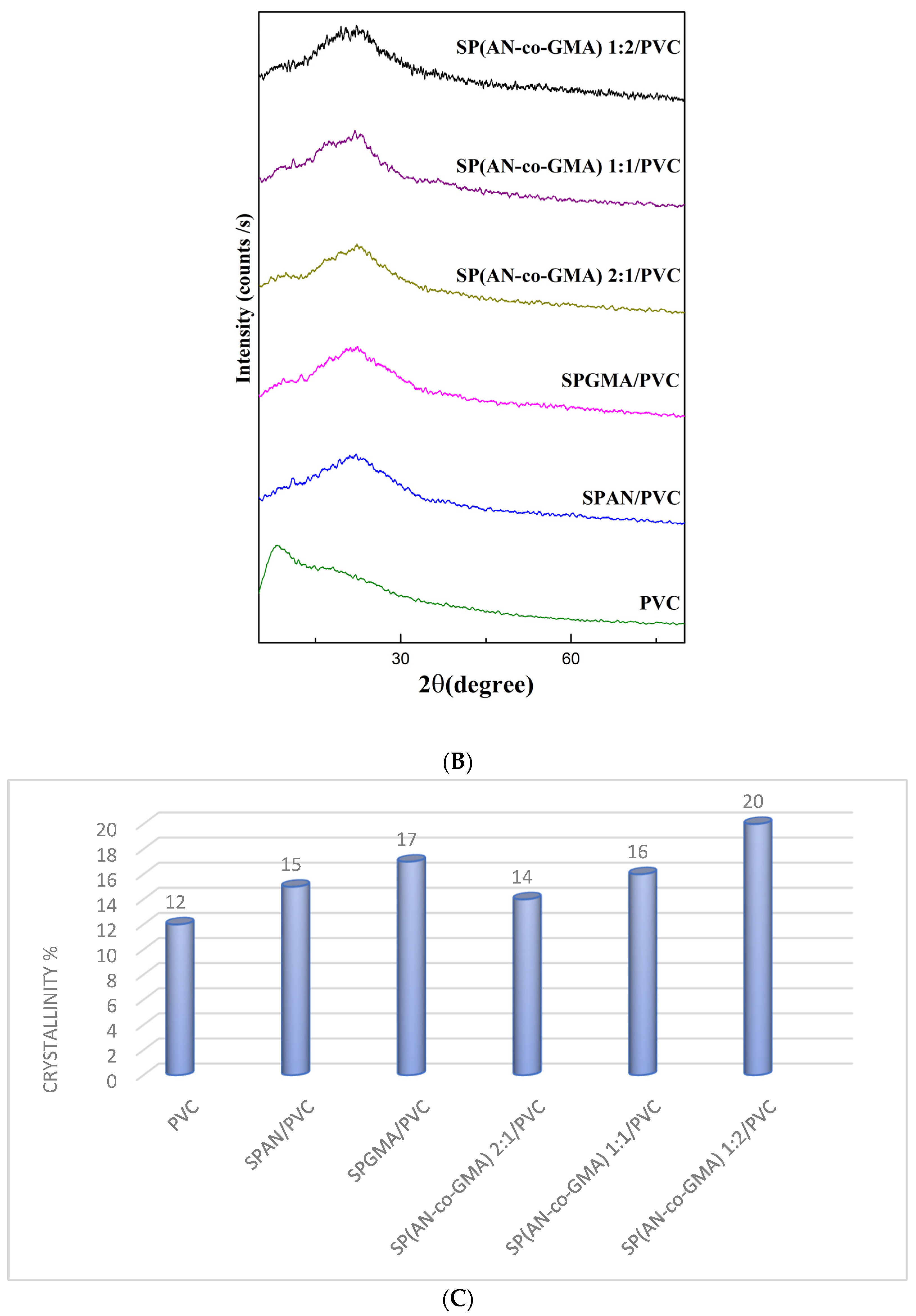
3.1.3. X-ray Diffractograms
3.2. Thermal Stability
3.3. Mechanical Properties
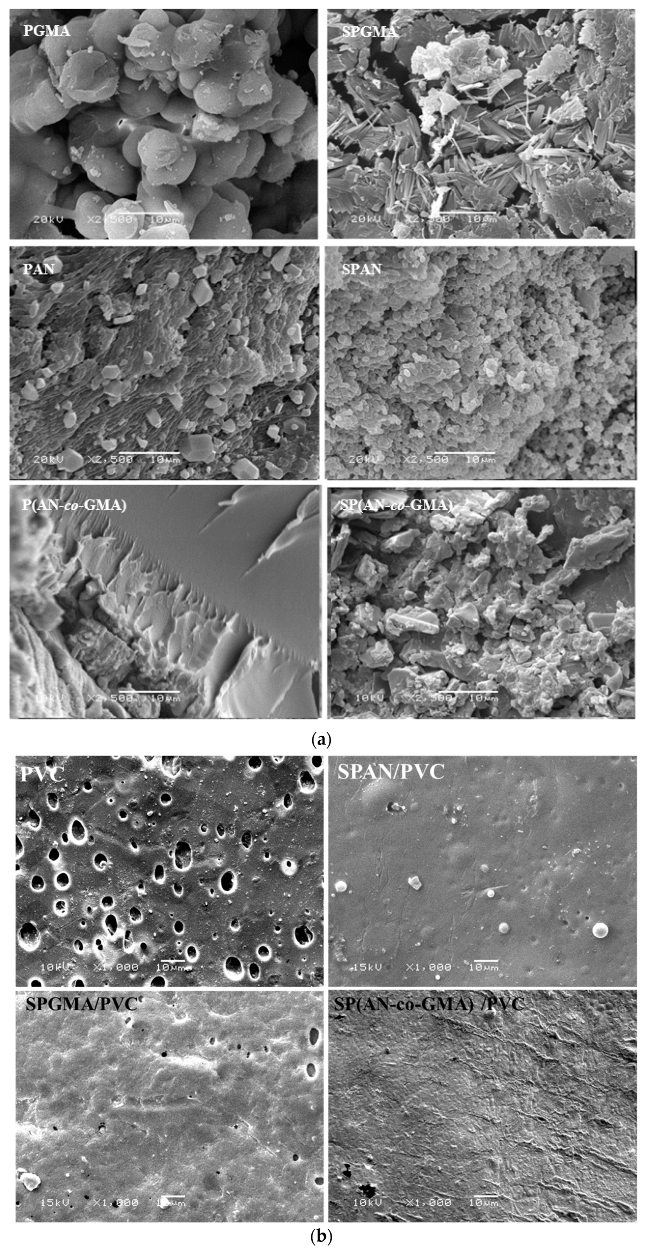
3.4. Morphological Features
3.5. Surface Roughness
3.6. Contact Angle
3.7. Ion Exchange Capacity
3.8. Water and Methanol Uptake
3.9. Methanol Permeability
4. Conclusions
Author Contributions
Funding
Data Availability Statement
Acknowledgments
Conflicts of Interest
References
- Song, K.; Lan, Y.; Zhang, X.; Jiang, J.; Sun, C.; Yang, G.; Yang, F.; Lan, H. A Review on Interoperability of Wireless Charging Systems for Electric Vehicles. Energies 2023, 16, 1653. [Google Scholar] [CrossRef]
- Mallick, R.K.; Thombre, S.B.; Shrivastava, N.K. Vapor feed direct methanol fuel cells (DMFCs): A review. Renew. Sustain. Energy Rev. 2016, 56, 51–74. [Google Scholar] [CrossRef]
- Daniel, G.; Yolanda, L. Polymer Electrolyte Membrane Fuel Cells (PEMFC) in automotive applications: Environmental relevance of the manufacturing stage. Smart Grid Renew. Energy 2011, 2, 4954. [Google Scholar]
- Jorissen, L.; Gogel, V.; Kerres, J.; Garche, J. New membranes for direct methanol fuel cells. J. Power Sources 2002, 105, 267–273. [Google Scholar] [CrossRef]
- Duangkaew, P.; Wootthikanokkhan, J. Methanol permeability and proton conductivity of direct methanol fuel cell membranes based on sulfonated poly(vinyl alcohol)-layered silicate nanocomposites. J. Appl. Polym. Sci. 2008, 109, 452–458. [Google Scholar] [CrossRef]
- Sun, C.; Zhang, H. Investigation of Nafion series membranes on the performance of iron-chromium redox flow battery. Int. J. Energy Res. 2019, 43, 8739–8752. [Google Scholar] [CrossRef]
- Xu, C.; Liu, X.; Cheng, J.; Scott, K. A polybenzimidazole/ionic-liquid-graphite-oxide composite membrane for high temperature polymer electrolyte membrane fuel cells. J. Power Sources 2015, 274, 922–927. [Google Scholar] [CrossRef]
- Abu-Saied, M.; El-Desouky, E.; Soliman, E.; Abd El-Naim, G. Novel sulfonated poly (vinyl chloride)/poly (2-acrylamido-2-methylpropane sulphonic acid) com-posites-based polyelectrolyte membranes for direct methanol fuel cells. Polym. Test. 2020, 89, 106604. [Google Scholar] [CrossRef]
- Elkady, M.; Abu-Saied, M.; Rahman, A.A.; Soliman, E.; Elzatahry, A.; Yossef, M.E.; Eldin, M.M. Nano-sulfonated poly (glycidyl methacrylate) cations exchanger for cadmium ions removal: Effects of operating parameters. Desalination 2011, 279, 152–162. [Google Scholar] [CrossRef]
- Abu-Saied, M.; Abdel-Halim, E.; Fouda, M.M.; Al-Deyab, S.S. Preparation and Characterization of Iminated Polyacrylonitrile for the Removal of Methylene Blue from Aqueous Solutions. Int. J. Electrochem. Sci. 2013, 8, 5121–5135. [Google Scholar] [CrossRef]
- Abdel-Hady, E.; El-Toony, M.; Abdel-Hamed, M.O. Grafting of glycidyl methacrylate/styrene onto polyvinyldine fluoride membranes for proton exchange fuel cell. Electrochim. Acta 2013, 103, 32–37. [Google Scholar] [CrossRef]
- Wang, A.; Bao, Y.; Weng, Z.; Huang, Z. Synthesis and Characterization of Proton-conducting Polymer Electrolytes Based on Acrylonitrile-Styrene Sulfonic Acid Copolymer/Layered Double Hydroxides Nanocomposites. Chin. J. Chem. Eng. 2008, 16, 938–943. [Google Scholar] [CrossRef]
- Pandey, R.P.; Shahi, V.K. Phosphonic acid grafted poly(ethyleneimine)-silica composite polymer electrolyte membranes by epoxide ring opening: Improved conductivity and water retention at high temperature. Int. J. Hydrogen Energy 2015, 40, 14235–14245. [Google Scholar] [CrossRef]
- Hasan, M.; Banerjee, A.N.; Lee, M. Enhanced thermo-optical performance and high BET surface area of graphene@PVC nanocomposite fibers prepared by simple facile deposition technique: N2 adsorption study. J. Ind. Eng. Chem. 2015, 21, 828–834. [Google Scholar] [CrossRef]
- Abu-Saied, M.; Fahmy, A.; Morgan, N.; Qutop, W.; Abdelbary, H.; Friedrich, J.F. Enhancement of Poly(vinyl chloride) Electrolyte Membrane by Its Exposure to an Atmospheric Dielectric Barrier Discharge Followed by Grafting with Polyacrylic Acid. Plasma Chem. Plasma Process. 2019, 39, 1499–1517. [Google Scholar] [CrossRef]
- Winter, M.; Brodd, R.J. What are Batteries, Fuel Cells, and Supercapacitors? ACS Publications: Washington, DC, USA, 2004. [Google Scholar]
- Yang, C.-C.; Chiu, S.-J.; Kuo, S.-C. Preparation of poly (vinyl alcohol)/montmorillonite/poly (styrene sulfonic acid) composite membranes for hydrogen–oxygen polymer electrolyte fuel cells. Curr. Appl. Phys. 2011, 11, S229–S237. [Google Scholar] [CrossRef]
- Abu-Saied, M.A.; Taha, T.H.; Elnaggar, E.M.; Amer, R.A.; Mansy, A.E.; Elkady, G.M. Green production of bio-ethanol from cellulosic fiber waste and its separation using polyacrylonitrile-co-poly methyl acrylate membrane. Cellulose 2018, 25, 6621–6644. [Google Scholar] [CrossRef]
- Yang, L.; Zeng, X.; Wang, W.; Cao, D. Recent progress in MOF-derived, heteroatom-doped porous carbons as highly efficient electrocatalysts for oxygen reduction reaction in fuel cells. Adv. Funct. Mater. 2018, 28, 1704537. [Google Scholar] [CrossRef]
- Zainoodin, A.; Kamarudin, S.; Masdar, M.S.; Daud, W.R.W.; Mohamad, A.; Sahari, J. High power direct methanol fuel cell with a porous carbon nanofiber anode layer. Appl. Energy 2013, 113, 946–954. [Google Scholar] [CrossRef]
- Muthumeenal, A.; Neelakandan, S.; Kanagaraj, P.; Nagendran, A. Synthesis and properties of novel proton exchange membranes based on sulfonated poly-ethersulfone and N-phthaloyl chitosan composites for DMFC applications. Renew. Energy 2016, 86, 922–929. [Google Scholar] [CrossRef]
- Sangeetha, D. Conductivity and solvent uptake of proton exchange membrane based on polystyrene (ethylene–butylene) polystyrene triblock polymer. Eur. Polym. J. 2005, 41, 2644–2652. [Google Scholar] [CrossRef]
- Radhi, M.M.; Tan, W.T.; Ab Rahman, M.Z.B.; Kassim, A.B. Synthesis and characterization of grafted acrylonitrile on polystyrene modified with activated car-bon using gamma-irradiation. Sci. Res. Essays 2012, 7, 790–795. [Google Scholar]
- Touheed, A.; Maab, H. Preparation and Characterization of Sulfonated Polyacrylamide from Polyacrylonitrile for Proton Conductive Membranes. J. Chin. Chem. Soc. 2012, 59, 1541–1547. [Google Scholar] [CrossRef]
- Dutta, P.; Kalita, B.; Gogoi, B.; Sarma, N.S. Development of Macroporousco-Polyesters of Glyceryl Methacrylate with Acrylonitrile and Styrene for Electrical Sensing of Ammonia Vapor. J. Phys. Chem. C 2015, 119, 17260–17270. [Google Scholar] [CrossRef]
- Mallakpour, S.; Abdolmaleki, A.; Tabebordbar, H. Production of PVC/α-MnO2-KH550 nanocomposite films: Morphology, thermal, mechanical and Pb (II) adsorption properties. Eur. Polym. J. 2016, 78, 141–152. [Google Scholar] [CrossRef]
- Ostrovskii, D.; Brodin, A.; Torell, L.M.; Appetecchi, G.B.; Scrosati, B. Molecular and ionic interactions in poly(acrylonitrile)- and poly(methylmetacrylate)-based gel electrolytes. J. Chem. Phys. 1998, 109, 7618–7624. [Google Scholar] [CrossRef]
- Dong, L.; Liu, X.D.; Zhao, X.T.; Dong, Y.C.; Cheng, B.W.; Zhuang, X.P.; Meng, D.D. Study on Raman Spectra of the Polyacrylonitrile Iron Complex Nanofibers. Appl. Mech. Mater. 2014, 513–517, 273–276. [Google Scholar] [CrossRef]
- Carron, K.; Cox, R. Qualitative Analysis and the Answer Box: A Perspective on Portable Raman Spectroscopy. Anal. Chem. 2010, 82, 3419–3425. [Google Scholar] [CrossRef]
- Zhu, D.Y.; Cao, G.S.; Qiu, W.L.; Rong, M.Z.; Zhang, M.Q. Self-healing polyvinyl chloride (PVC) based on microencapsulated nucleophilic thiol-click chemistry. Polymer 2015, 69, 1–9. [Google Scholar] [CrossRef]
- Koohmareh, G.A.; Hajian, M.; Fallahi, H. Graft Copolymerization of Styrene from Poly(vinyl alcohol) via RAFT Process. Int. J. Polym. Sci. 2011, 2011, 1–7. [Google Scholar] [CrossRef]
- Schmälzlin, E.; Moralejo, B.; Rutowska, M.; Monreal-Ibero, A.; Sandin, C.; Tarcea, N.; Popp, J.; Roth, M.M. Raman Imaging with a Fiber-Coupled Multichannel Spectrograph. Sensors 2014, 14, 21968–21980. [Google Scholar] [CrossRef] [PubMed] [Green Version]
- Ellahi, S.; Hester, R.; Williams, K. Waveguide resonance Raman spectroscopy of degraded PVC. Spectrochim. Acta Part A Mol. Biomol. Spectrosc. 1995, 51, 549–553. [Google Scholar] [CrossRef]
- Hasan, M.; Kumar, R.; Barakat, M.A.; Lee, M. Synthesis of PVC/CNT nanocomposite fibers using a simple deposition technique for the application of Alizarin Red S (ARS) removal. RSC Adv. 2015, 5, 14393–14399. [Google Scholar] [CrossRef]
- Nguyen-Thai, N.U.; Hong, S.C. Controlled architectures of poly(acrylonitrile-co-itaconic acid) for efficient structural transformation into carbon materials. Carbon 2014, 69, 571–581. [Google Scholar] [CrossRef]
- Kasim, F.A.; Mahdi, M.A.; Hassan, J.J.; Al-Ani, S.K.J.; Kasim, S.J. Preparation and optical properties of CdS/Epoxy nanocomposites. Int. J. Nanoelectron. Mater. 2012, 5, 57–66. [Google Scholar]
- Guhan, S.; Muruganantham, R.; Sangeetha, D. Development of a solid polymer electrolyte membrane based on sulfonated poly(ether ether)ketone and polysulfone for fuel cell applications. Can. J. Chem. 2012, 90, 205–213. [Google Scholar] [CrossRef]
- Da Silva, M.A.; Vieira, M.G.A.; Maçumoto, A.C.G.; Beppu, M.M. Polyvinylchloride (PVC) and natural rubber films plasticized with a natural polymeric plasti-cizer obtained through polyesterification of rice fatty acid. Polym. Test. 2011, 30, 478–484. [Google Scholar] [CrossRef] [Green Version]
- Lee, S.; Kim, J.; Ku, B.-C.; Kim, J.; Joh, H.-I. Structural Evolution of Polyacrylonitrile Fibers in Stabilization and Carbonization. Adv. Chem. Eng. Sci. 2012, 2, 275–282. [Google Scholar] [CrossRef] [Green Version]
- Misra, P.; Chitanda, J.M.; Dalai, A.K.; Adjaye, J. Immobilization of fluorenone derived π-acceptors on poly (GMA-co-EGDMA) for the removal of refractory nitrogen species from bitumen derived gas oil. Fuel 2015, 145, 100–108. [Google Scholar] [CrossRef]
- Edwards, H.; Brown, D.; Dale, J.; Plant, S. Raman spectroscopy of sulfonated polystyrene resins. Vib. Spectrosc. 2000, 24, 213–224. [Google Scholar] [CrossRef]
- Abu-Saied, M.; Soliman, E.; Al Desouki, E. Development of Proton Exchange Membranes Based on Chitosan Compositeed with Poly (2-Acrylamido-2-Methylpropane Sulfonic Acid) for Fuel Cells applications. Mater. Today Commun. 2020, 25, 101536. [Google Scholar] [CrossRef]
- Pang, J.; Jin, X.; Wang, Y.; Feng, S.; Shen, K.; Wang, G. Fluorinated poly (arylene ether ketone) containing pendent hexasulfophenyl for proton exchange mem-brane. J. Membr. Sci. 2015, 492, 67–76. [Google Scholar] [CrossRef]
- Jung, B. Preparation of hydrophilic polyacrylonitrile composite membranes for ultrafiltration. J. Membr. Sci. 2004, 229, 129–136. [Google Scholar] [CrossRef]
- Wang, J.; Yue, Z.; Economy, J. Preparation of proton-conducting composite membranes from sulfonated poly(ether ether ketone) and polyacrylonitrile. J. Membr. Sci. 2007, 291, 210–219. [Google Scholar] [CrossRef]
- Anirudhan, T.S.; Senan, P. Adsorptive potential of sulfonated poly (glycidylmethacrylate)-grafted cellulose for separation of lysozyme from aqueous phase: Mass transfer analysis, kinetic and equilibrium profiles. Colloids Surf. Aphysicochem. Eng. Asp. 2011, 377, 156–166. [Google Scholar] [CrossRef]
- Chaleawlert-Umpon, S.; Pimpha, N. Preparation of magnetic polymer microspheres with reactive epoxide functional groups for direct immobilization of antibody. Colloids Surf. Aphysicochem. Eng. Asp. 2012, 414, 66–74. [Google Scholar] [CrossRef]
- Menges, G.; Boden, H.-E. Failure of Plastics; Brostow, W., Corneliussen, R.D., Eds.; Hanser Publishers: Munich, Germany, 1986. [Google Scholar]
- Lee, S.-B.; Kim, Y.-J.; Ko, U.; Min, C.-M.; Ahn, M.-K.; Chung, S.-J.; Moon, I.-S.; Lee, J.-S. Sulfonated poly(arylene ether) membranes containing perfluorocyclobutyl and ethynyl groups: Increased mechanical strength through chain extension and crosslinking. J. Membr. Sci. 2014, 456, 49–56. [Google Scholar] [CrossRef]
- Eldin, M.S.M.; Soliman, E.A.; Hassan, E.A.; Abu-Saied, M.A.A.-S. Immobilized Metal Ions Cellophane–PGMA-Grafted Membranes for Affinity Separation of b-Galactosidase Enzyme. I. Preparation and Characterization. J. Appl. Polym. Sci. 2009, 111, 2647–2656. [Google Scholar] [CrossRef]


| Polymer | Stage | Temperature Range °C | Weight Loss% | Thermal Decomposition |
|---|---|---|---|---|
| PGMA | First | 0–145 | 1.5 | About 120 °C, due to water evaporation. About 300 °C is attributed to polymer surface decomposition and random chain scission. |
| Second | 145–300 | 7 | ||
| Third | 300–428 | 80 | ||
| Fourth | 428–700 | 10 | ||
| SPGMA | First | 0–132 | 7 | About 120 °C, due to loss of water. At 250 °C correspond to the decomposition of the sulfonic groups. |
| Second | 132–250 | 11 | ||
| Third | 250–500 | 25 | ||
| Fourth | 500–700 | 10 | ||
| PAN | First | 0–120 | 2.58 | Above 300 °C, due to the backbone degradation of PAN. |
| Second | 120–350 | 20 | ||
| Third | 350–575 | 15.2 | ||
| Fourth | 575–700 | 9.6 | ||
| SPAN | First | 0–164 | 5 | About 250 °C corresponds to the decomposition of the sulfonic groups. |
| Second | 164–364 | 5 | ||
| Third | 364–471 | 3 | ||
| Fourth | 471–700 | 20 | ||
| P(AN-co-GMA) | First | 0–134 | 5.2 | About 400 °C corresponds to the degradation and deacetylation of the polymer. |
| Second | 134–334 | 3.3 | ||
| Third | 334–483 | 80.33 | ||
| Fourth | 483–700 | 4.75 | ||
| SP(AN-co-GMA) | First | 0–136 | 6.5 | Around 250 °C is due to the thermal degradation of the sulphonic acid groups. |
| Second | 136–236 | 7 | ||
| Third | 236–473 | 35 | ||
| Fourth | 473–700 | 4 | ||
| PVC | First | 0–150 | 10 | Below 100 °C can be attributed to the evaporation of trapped THF. At 384.4 °C, which results from the breaking of the C-Cl bond. Above 400 °C, due to the decomposition of the polymer backbones. |
| Second | 150–280 | 38 | ||
| Third | 280–469 | 32 | ||
| Fourth | 469–800 | 14.5 | ||
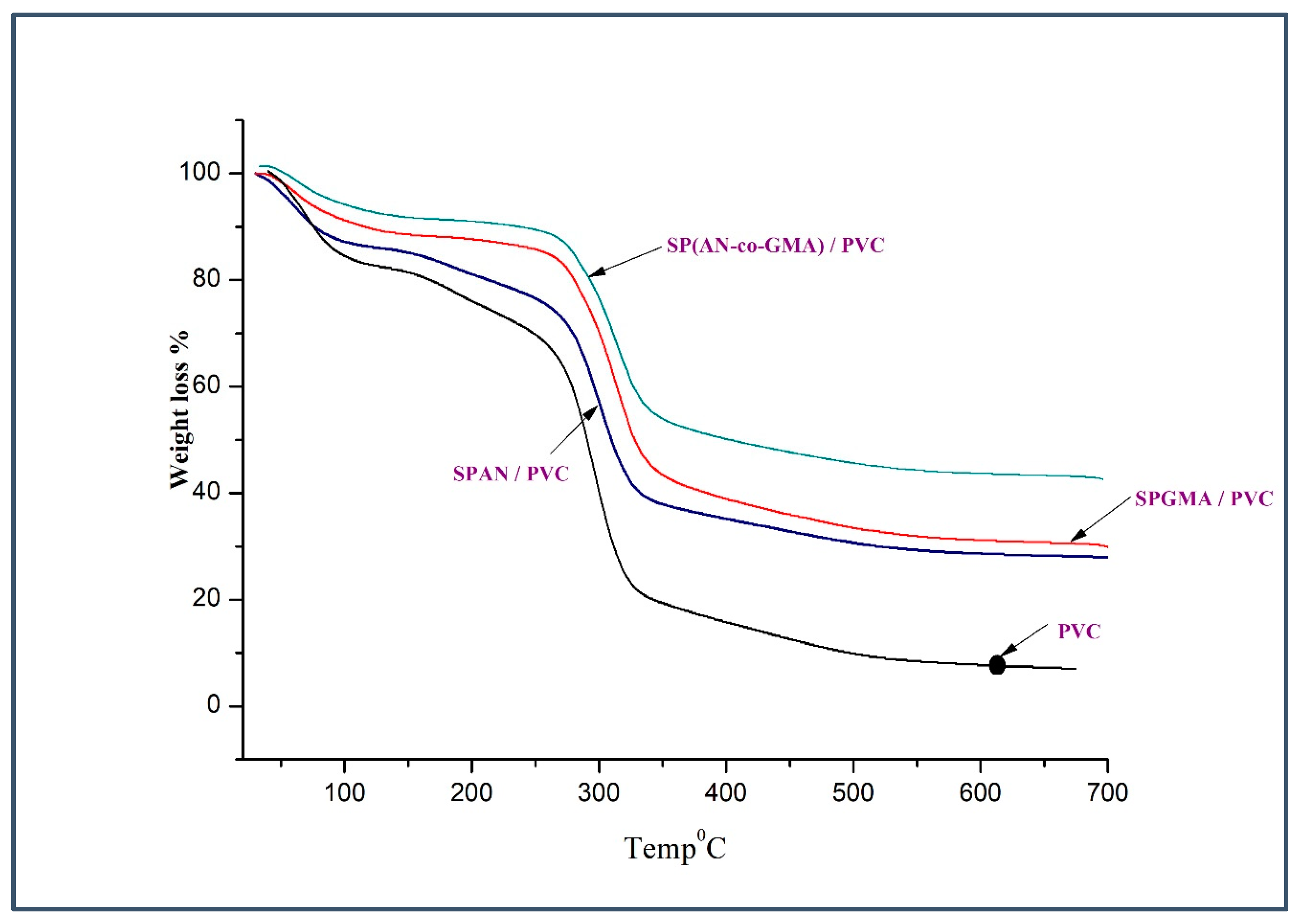
| SPAN/PVC | First | 0–166 | 10 | The TGA data represent that the SPAN/PVC electrolyte membranes are thermally stable up to around 200 °C, which demonstrates sufficient thermal properties for application in DMFC. |
| Second | 166–264 | 10 | ||
| Third | 264–449 | 32 | ||
| Fourth | 449–800 | 20 | ||
| SPGMA/PVC | First | 0–170 | 12.58 | The TGA data represent that the SPGMA/PVC electrolyte membranes are thermally stable up to around 200 °C, which demonstrates sufficient thermal properties for application in DMFC. |
| Second | 170–270 | 10 | ||
| Third | 270–475 | 15.2 | ||
| Fourth | 475–800 | 9.6 | ||
| SP(AN-co-GMA)/PVC | First | 0–136 | 5.5 | The TGA data represent that the SP(AN-co-GMA)/PVC electrolyte membranes are thermally stable up to around 200 °C, which demonstrates sufficient thermal properties for application in DMFC. |
| Second | 136–250 | 7 | ||
| Third | 250–473 | 35 | ||
| Fourth | 473–800 | 4 |
| Polyelectrolyte Membrane | Thickness (mm) | Tensile Strength (MPa) | Elongation at Break (%) |
|---|---|---|---|
| Nafion® 117 | 0.183 | 12.2 ± 0.1 | 18.2 |
| PVC | 0.14 ± 0.02 | 6.22 ± 0.50 | 8.66 ± 0.60 |
| SPAN/PVC | 0.18 ± 0.08 | 1.73 ± 0.10 | 54.10 ± 2.20 |
| SPGMA/PVC | 0.18 ± 0.09 | 1.12 ± 0.20 | 114.51 ± 5.80 |
| SP(AN-co-GMA) 2:1/PVC | 0.14 ± 0.08 | 0.94 ± 0.08 | 23.65 ± 1.30 |
| SP(AN-co-GMA) 1:1/PVC | 0.10 ± 0.07 | 1.01 ± 0.09 | 25.42 ± 2.20 |
| SP(AN-co-GMA) 1:2/PVC | 0.15 ± 0.07 | 0.96 ± 0.05 | 20.21 ± 1.50 |
| Polyelectrolyte Membrane | Roughness (µm) |
|---|---|
| Nafion® 117 | 0.09 |
| PVC | 1.10 ± 0.02 |
| SPAN/PVC | 1.10 ± 0.05 |
| SPGMA/PVC | 3.52 ± 0.10 |
| SP(AN-co-GMA) 2:1/PVC | 3.03 ± 0.11 |
| SP(AN-co-GMA) 1:1/PVC | 2.74 ± 0.10 |
| SP(AN-co-GMA) 1:2/PVC | 3.08 ± 0.10 |
| Polyelectrolyte Membrane | Mean Theta (θ) |
|---|---|
| Nafion® 117 | 110 |
| PVC | 46.31 ± 1.20 |
| SPAN/PVC | 21.07 ± 2.08 |
| SPGMA/PVC | 23.04 ± 3.09 |
| SP(AN-co-GMA) 2:1/PVC | 30.07 ± 3.08 |
| SP(AN-co-GMA) 1:1/PVC | 22.95 ± 3.07 |
| SP(AN-co-GMA) 1:2/PVC | 20.25 ± 3.17 |
| Polyelectrolyte Membrane | IEC (meq/g) |
|---|---|
| Nafion® 117 | 0.91 |
| PVC | 0.01 ± 0.01 |
| SPAN/PVC | 0.20 ± 0.05 |
| SPGMA/PVC | 0.22 ± 0.05 |
| SP(AN-co-GMA) 2:1/PVC | 0.37 ± 0.02 |
| SP(AN-co-GMA) 1:1/PVC | 0.38 ± 0.02 |
| SP(AN-co-GMA) 1:2/PVC | 0.48 ± 0.05 |
| Polyelectrolyte Membrane | Water Uptake (%) | Methanol Uptake (%) |
|---|---|---|
| Nafion® 117 | 65.44 | 22 |
| PVC | 00.05 ± 0.01 | 14.51 ± 0.08 |
| SPAN/PVC | 25.16 ± 1.10 | 16.26 ± 0.50 |
| SPGMA/PVC | 16.41 ± 1.05 | 07.77 ± 0.08 |
| SP(AN-co-GMA) 2:1/PVC | 20.10 ± 1.50 | 12.06 ± 0.09 |
| SP(AN-co-GMA) 1:1/PVC | 18.10 ± 1.05 | 14.14 ± 0.10 |
| SP(AN-co-GMA) 1:2/PVC | 17.65 ± 1.04 | 13.92 ± 0.20 |
| Polyelectrolyte Membrane | Methanol Permeability (cm2 s−1) | Efficiency Factor |
|---|---|---|
| Nafion® 117 | 3.39 × 10⁻⁶ | 2.6 × 10⁵ |
| PVC | 9.36 × 10⁻⁷ | - |
| SPAN/PVC | 9 × 10⁻⁷ | 6 × 10⁵ |
| SPGMA/PVC | 9.16 × 10⁻⁷ | 5.7 × 10⁵ |
| SP(AN-co-GMA)/PVC | 8.7 × 10⁻⁷ | 6.6 × 10⁵ |
Disclaimer/Publisher’s Note: The statements, opinions and data contained in all publications are solely those of the individual author(s) and contributor(s) and not of MDPI and/or the editor(s). MDPI and/or the editor(s) disclaim responsibility for any injury to people or property resulting from any ideas, methods, instructions or products referred to in the content. |
© 2023 by the authors. Licensee MDPI, Basel, Switzerland. This article is an open access article distributed under the terms and conditions of the Creative Commons Attribution (CC BY) license (https://creativecommons.org/licenses/by/4.0/).
Share and Cite
El Desouky, E.A.; Soliman, E.A.; Al-Rasheed, H.H.; El-Faham, A.; Abu-Saied, M.A. Novel Proton Exchange Membranes Based on Sulfonated Poly(acrylonitrile-co-glycidyl methacrylate)/Poly(vinyl chloride) Composite. Sustainability 2023, 15, 11166. https://doi.org/10.3390/su151411166
El Desouky EA, Soliman EA, Al-Rasheed HH, El-Faham A, Abu-Saied MA. Novel Proton Exchange Membranes Based on Sulfonated Poly(acrylonitrile-co-glycidyl methacrylate)/Poly(vinyl chloride) Composite. Sustainability. 2023; 15(14):11166. https://doi.org/10.3390/su151411166
Chicago/Turabian StyleEl Desouky, Eman A., Emad A. Soliman, Hessa H. Al-Rasheed, Ayman El-Faham, and M. A. Abu-Saied. 2023. "Novel Proton Exchange Membranes Based on Sulfonated Poly(acrylonitrile-co-glycidyl methacrylate)/Poly(vinyl chloride) Composite" Sustainability 15, no. 14: 11166. https://doi.org/10.3390/su151411166