Article

Mechanism of Nozzle Position Affecting Coalbed Methane Mining in High-Pressure Air Blasting

1
School of Civil Engineering, Henan Polytechnic University, Jiaozuo 454000, China
2
College of Civil Engineering, Luoyang Institute of Science and Technology, Luoyang 471023, China
*
Authors to whom correspondence should be addressed.
Sustainability 2023, 15(14), 11171; https://doi.org/10.3390/su151411171
Submission received: 21 June 2023 / Revised: 8 July 2023 / Accepted: 16 July 2023 / Published: 18 July 2023

Abstract

:
The use of clean energy is an important part of promoting sustainable energy development. As a clean energy source, coalbed methane, during the mining process, the position of the nozzle can influence coalbed methane extraction efficiency by affecting the cracking effect of coal. To investigate the impact of nozzles on the effect of coal fracture, a test of simulated coal by high-pressure air blasting was executed using nozzles 100 mm, 200 mm, and 250 mm from the orifice. Based on the test results and theories of fracture damage mechanics, two damage fracture models were established for the nozzles located in the middle-upper and middle-lower of the blasthole, respectively. The fracturing process and increased permeability mechanism of the coal were revealed by these two models. The results show that: when the nozzle is 100 mm from the orifice, the high-pressure air impacts the blasthole wall first, similar to a uniform expansion. Multiple longitudinal cracks are formed penetrating the coal. The permeability of the coal seam is greatly improved. When the nozzle is 200 mm and 250 mm from the orifice, the high-pressure air first impacts the bottom of the blasthole. The bottom hole angle and apex hole angle first form horizontal cracks while longitudinal cracks only appear at the same depth as the blasthole. The nozzle is 250 mm from the orifice to form a compaction zone at the bottom of the blasthole. The crack density is small and the tangential depth is shallow, which is not conducive to coalbed methane mining. The results of the research offer a theoretical framework and point of reference for the use of high-pressure air blasting technology in the extraction of coalbed methane (CBM).

1. Introduction

As an associated gas adsorbed in coal seams, coalbed methane (gas) is an important clean energy that can promote energy sustainable development [1,2]. China has one of the abundant known coalbed methane in the world, with detected reserves of 36.8 trillion cubic meters. Improving the mining rate of coalbed methane is not only a reliable way to eliminate safety hazards in coal mines, but also an important measure to accomplish the strategic target of “carbon peak and carbon neutrality” [3,4]. Since sources of coalbed methane in China exist in low-permeability coal seams with complex geological structures, coalbed methane mining has the problem of large reserves but low gas production [5]. The nature of coal cracks is a key factor, changing coal seam permeability and affecting the exploitation of coalbed methane [6]. Therefore, confronted with the current dilemma of low coal seam permeability and hard coalbed methane extraction, a new blasting technology suitable for enhancing low permeability coal seam permeability is urgently required, which has become a major problem to be solved by China and even the world [7,8].
In the study of coal seam fracturing and coalbed methane mining, researchers both domestically and internationally have consistently produced huge findings. Zhao et al. [9] performed research on blasting coal by altering blasthole diameters and spacing between blastholes. Through comparing the cloud images of coal crack distribution, they found that when the diameter of the blasthole was set at 113 mm and the distance between the two holes was 5.5 mm, the coal formed more run through cracks. Ti et al. [10] conducted research based on the Tingnan Coal Mine, a numerical model of blasting coal with different blasthole spacing was established, and the effect of blasthole spacing on coal crack propagation was studied. Iwan Shipovskii1 et al. [11] conducted simulations to examine how blasting rates affected the growth of coal cracks. It was found that the crack growth of coal was closely related to the blasting speed, and had nothing to do with the design of explosives. Hu et al. [12] carried out hydraulic impact tests on multi-layer (soft coal, hard coal) combined coals and explored the mechanism of crack propagation in combined coals under hydraulic impact. Wang et al. [13] constructed a dynamic mechanical model of coal crack growth under carbon dioxide blasting, and divided the process of carbon dioxide blasting coal into three stages. K.H.S.M. Sampath et al. [14] adopted CT scanning technology and the evolution process of coal micro-cracks under S-CO2 interaction was studied. The results showed that although the overall cracks in coal continued to increase with the increase in explosion time, the crack growth in each section was not the same.
At present, the methods for improving coalbed methane extraction by increasing the permeability of coal seams have certain limitations.For example, the drilling and blasting method has the disadvantage of misfiring [15]. CO2 blasting features a boundedness of expansion range for coal seam cracks in the extraction of coalbed methane [16,17]. The hydraulic fracturing technique has sparked intense debate among academics due to fatal issues including groundwater pollution and resource waste [18]. With the advancement of ecological civilization construction, high-pressure air blasting, as a kind of coal seam fracturing technology with a better fracturing effect, higher security, and the characteristics of environmental protection greener, has attracted the attention of scholars [19].
High-pressure air blasting is a physical blasting technology that passes, pressurizes, stores, and releases an external air source to achieve coal fracturing [20]. This technology adopts low-cost ambient air as the gas source, which not only reduces the cost of raw materials but also avoids gas ignition caused by explosives. Therefore, high-pressure air blasting is an efficient, safe, and green technology applicable and suitable for coalbed methane mining [21,22]. However, scholars at home and abroad have conducted little research on the expansion of coal cracks caused by high-pressure air blasting, especially in the aspect of the influence of nozzle position on coal crack expansion. Therefore, from the perspective of high-pressure air blasting coal, this paper carried out experiments on high-pressure air blasting coal with nozzles in different positions, and studied the mechanism of coal crack propagation caused by nozzles in different positions. The research route of this paper is shown in Figure 1. The results of the study serve as a reference for the use of high-pressure air blasting in the coalbed methane mining industry.

2. Materials and Methods

2.1. A Brief Introduction to the Test Equipment

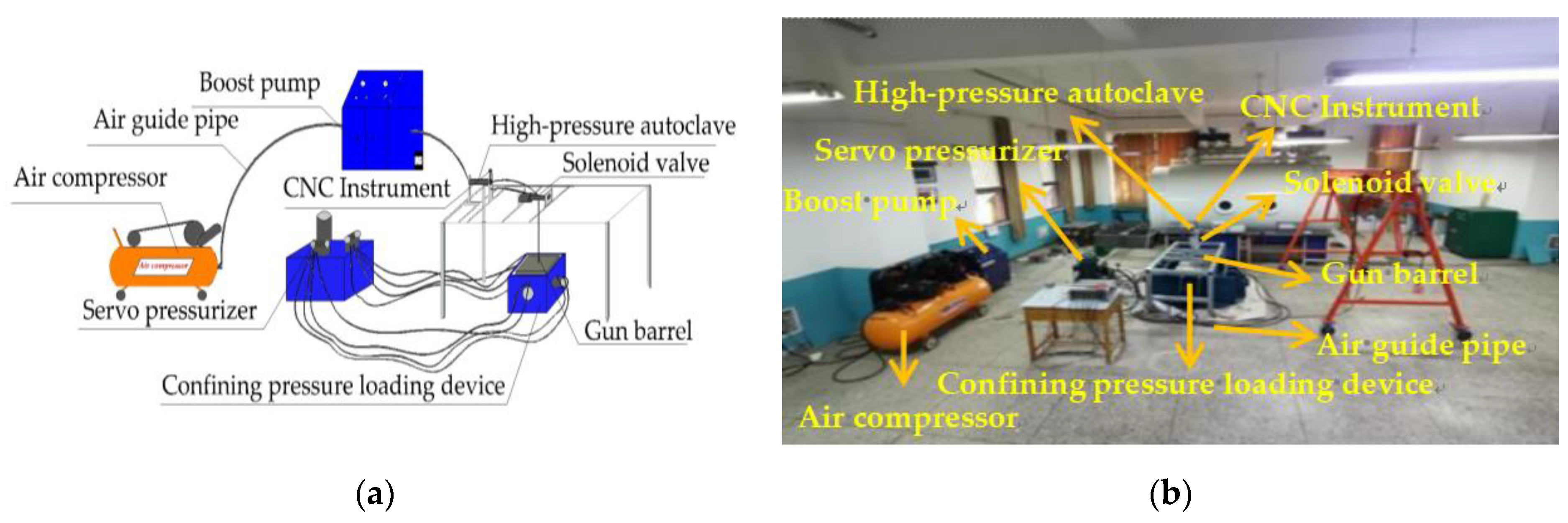
To study the mechanism of coal crack propagation caused by high-pressure air blasting with different positions of the nozzle, high-pressure air blasting tests were carried out using the existing instruments in a laboratory. The high-pressure air blasting test system mainly includes a gas-pressurized storage system, an air pressure control system, a high-pressure air release system, and a confining pressure loading device. The structure diagram and physical device of the high-pressure air explosion test system are shown in Figure 2.

2.2. Experimental Protocol

Coal is formed as a result of a long-lasting chemical reaction and deposition, so it is a tiny heterogeneous body with numerous micro-voids, micro-cracks, etc. [23,24]. If the test was carried out with raw coal, which needed to go through three stages, covering collection, transportation, and processing into a standard shape. This was likely to lead to the accumulation of original damage to the coal, thus increasing the difficulty in exploring the laws of coal crack propagation and dynamic damage evolution. Therefore, the simulated coal block was adopted to replace the raw coal to carry out the test. The basic mechanical properties of hard coal simulated in this experiment are shown in Table 1. During the production process, a material ratio was used for the simulated coal block-making, as shown in Table 2. A total of six simulated cube coal blocks were designed, the length of which was 500 mm. In the center of the model coal block, as shown in Figure 3a, a blasthole was reserved with a cylinder with a diameter of 20 mm and a height of 300 mm. The simulated coal block achieved a set of physical and mechanical properties, as shown in Table 3. The physical parameters are fundamentally the same as those of hard coal.
The simulated coal blocks with no visible cracks on the surface can be used for hole sealing. First, divide the simulated coal blocks into three groups for sealing and place the nozzles at 100 mm, 200 mm, and 250 mm from the orifice. Among them, the working condition corresponding to 100 mm is that the nozzle is located in the middle-upper part of the blasthole, and the 200 mm and 250 mm are in the middle-lower parts. Fix the nozzles with adhesive to ensure good sealing, as shown in Figure 3b. To make sure the test results are accurate, two parallel test pieces are made for each group of tests. Before the test, the high-pressure air blasting device needs to be inspected and debugged. When the test block is placed in the bearing platform, it should be clamped by the pressure devices on both sides. The confining pressure loading strength in both x and y directions is designed to be 6 MPa, and the impact pressure of high-pressure air is designed to be 25 MPa. The high-pressure air blasting test is shown in Figure 3c.

3. Results and Discussion

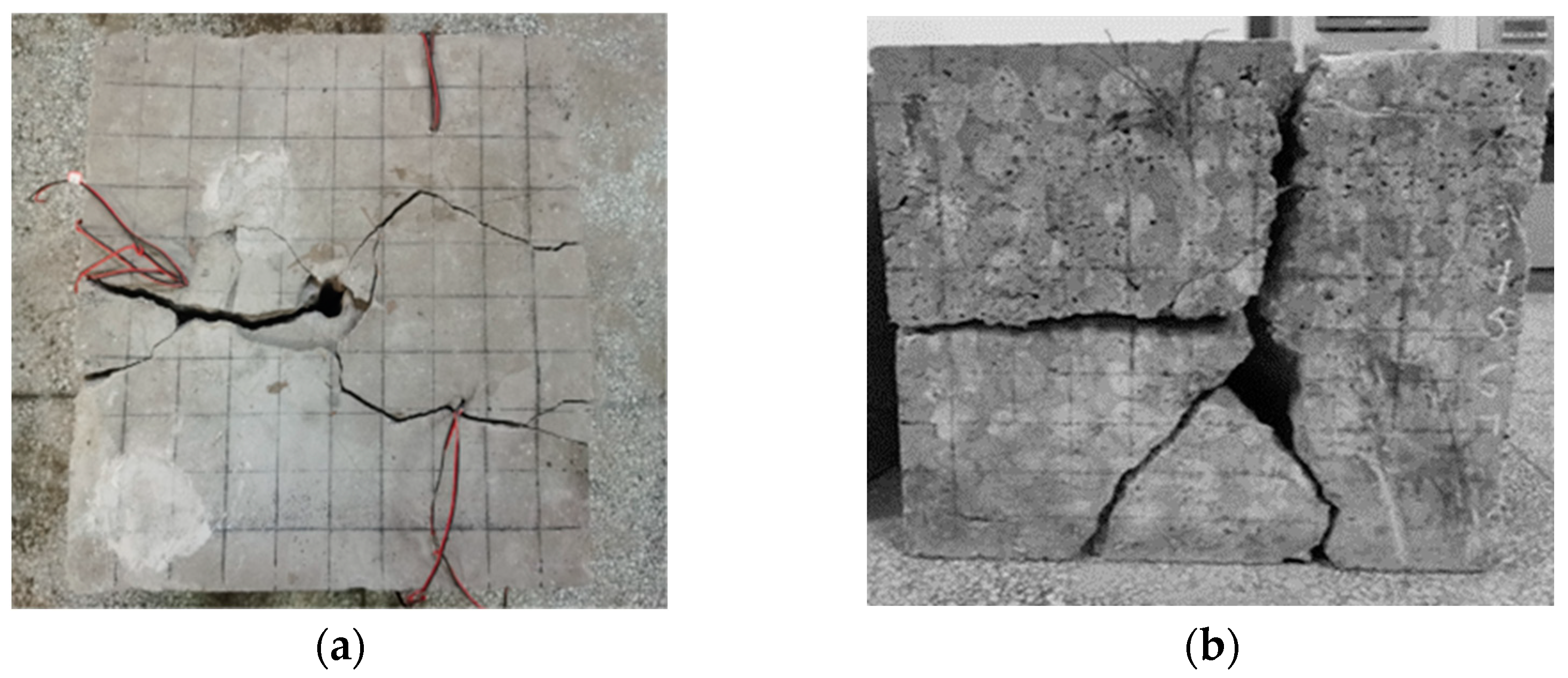
Figure 4a shows the outcomes of simulated coal exploded by high-pressure air using a nozzle at a distance of 100 mm from the orifice. According to the figure, on the top of the coal, it can be seen that a pulverization zone or a blast funnel does not appear in the area around the blasthole. The material around the blasthole was fractures in the direction of the largest main stress under stress wave disturbance. The primary fractures near the pore walls form an initial crack to enlarge. With characteristics of low viscosity, high diffusivity, and zero surface tension, high-pressure air is more likely to spread to the far-reaching areas of the coal. In the middle and far-reaching areas of blasting, gas gathers at the tip of the crack and forms a quasi-static stress field. The micro-fractures in the middle and far-reaching coal continue to expand under the combined loads of the quasi-static stress field and original rock stress. Then, the cracks interlace with each other to form longitudinal main cracks running through the coal. According to Figure 4b, the side of the coal has a sizable crack hole that is primarily brought on by the following two causes. (1) The simulated coal possesses low intensity and weak discrete mechanical properties. After cracks start to emerge in the coal, the high-pressure air repeatedly impacts and erodes them, causing the coal powder to fall off and the crack opening to enlarge. (2) The tested block and the confining pressure device touch the edge, and the damage to the coal increases under the influence of reflected tensile stress. In addition, the high-pressure air infiltrates the primary fracture and the fracture loses its stability to propagate, thus forming multiple short, narrow secondary cracks in different directions around the primary cracks. The formation of secondary cracks makes the crack grid of the coal more complex.
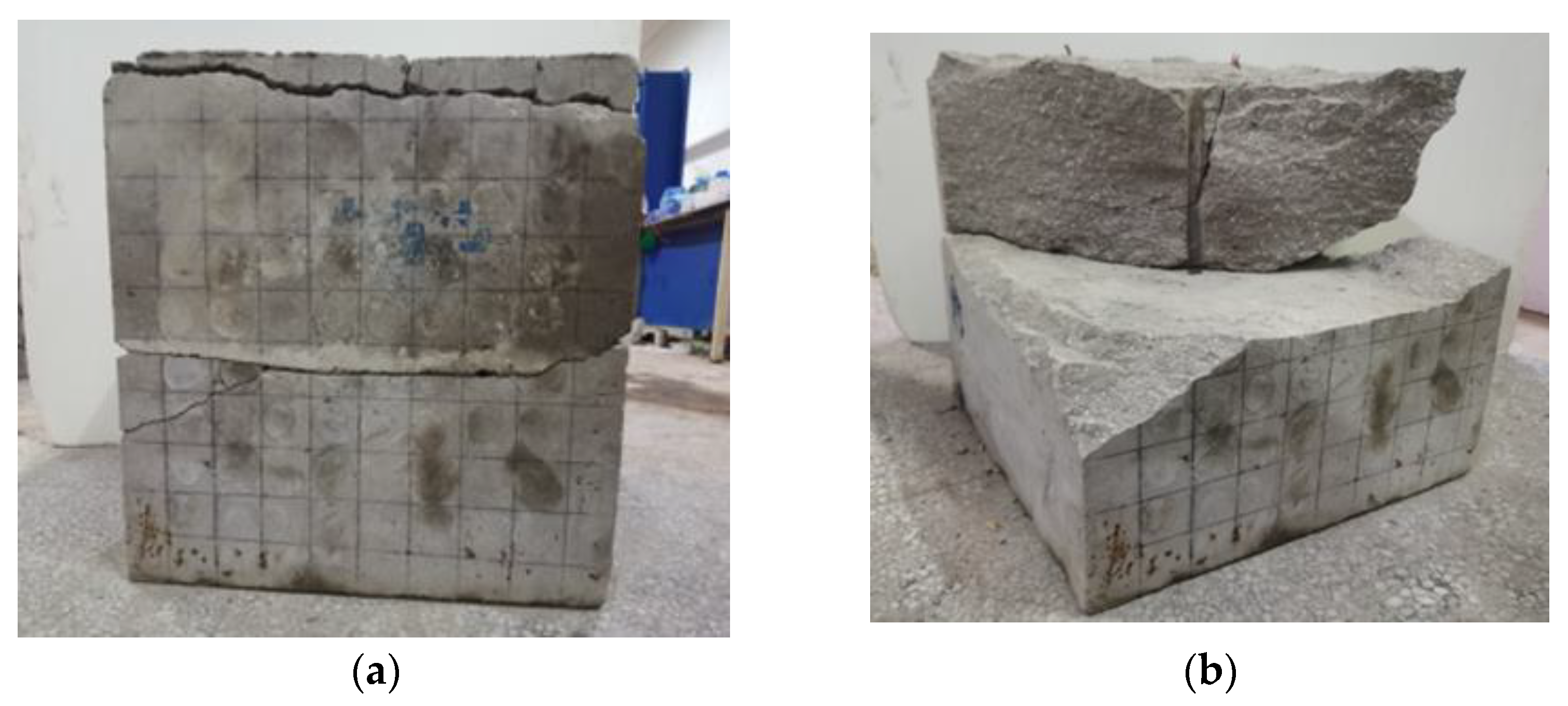
The high-pressure air blasting simulation coal test results are shown in Figure 5a, with the nozzle located in the middle-lower parts. The figure shows that there is no complicated crack grid within the coal. When the blasthole bottom is impacted by high-pressure air, stress concentration builds up at both the bottom and top of the hole in turn, so cracks begin to form from the bottom blasthole first, and then a straight horizontal main crack forms at the bottom of the hole and runs through the coal. Due to the weakening of the strength of the airflow impacting the top of the hole and the strengthening of the influence of the confining pressure loading on the crack growth, the horizontal cracks on the top of the hole have what appear as wavy shapes. Since the horizontal cracks at both ends of the blasthole weaken the ability of the longitudinal cracks in the coal to propagate, the longitudinal cracks in the coal only form in the depth range of blastholes, as shown in Figure 5b. Because of the buildup of a tiny amount of energy and high-pressure air, no cracks form in the lower area of the hole bottom. The crack wall comes off due to being repeatedly impacted by high-pressure air. However, when the nozzle is 250 mm away from the orifice, a compacted area is formed at the bottom of the hole.

4. Damage Fracture Process and Mechanism of Blasting Coal Caused by Different Positions of Nozzles

According to engineering practice and test results, the position of the nozzle during high-pressure air blasting can affect coal crack propagation. To explore the influence of the position of the nozzle on the damage characteristics of the coal mass, combined with the impact process of the high-pressure air in the blasthole and the attenuation law of the stress wave, two models of coal damage fracture with the nozzle in the middle-upper and the middle-lower part of the blasthole were established.

4.1. Damage Fracture Model of Coal with the Nozzle Located in the Middle-Upper Part

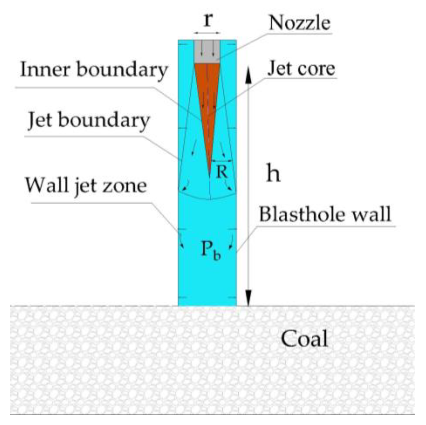
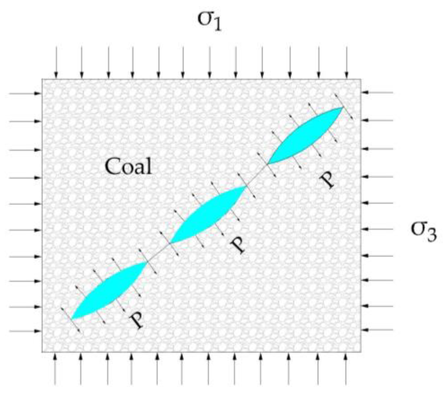
In the initial stage, when the high-pressure air is impacted into the blasthole, the high-pressure air essentially impacts downward in a vertical direction due to the small jet diffusion angle. During this process, the boundaries of the jets on both sides are constantly exchanging energy with the surrounding static air particles. The air at the boundary of the jet is continuously entrained in the gas to flow together. While the radius of the jet is still expanding, the speed of impact continues to slow down [25]. The direction of the jet changes when the jet boundary impacts the wall of the borehole. Gas molecules collide with each other. The force on the blasthole wall, when struck by the high-pressure air, is comparable to that of a uniform load. The schematic diagram of the high-pressure air jet flow with the nozzle in the middle-upper part of the blasthole is shown in Figure 6.
The mechanical properties of coal are similar to those of quasi-brittle materials, and the tensile strength of coal is much lower than the compressive strength. The expansion wave that is formed by the accumulation of high-pressure air in the blasthole causes the elastic compression of the hole wall to eventually lead to generate a stress wave and the medium inside the coal being compressed. Under the stress wave disturbance, the original crack around the blasthole loses stability and propagates. The area surrounding the blasthole forms tangential tensile stress as a result of the force of the stress wave. When the tangential tensile stress σ e reaches the dynamic tensile strength of the coal   σ u , initial cracks form around the blasthole wall [26]. The coal damage fracture model, with the nozzle in the middle-upper of the blasthole, was created by combining the effects of stress waves, high-pressure air, and original rock stress for the spread of coal cracks. This model is shown in Figure 7. Assuming, in the vertical and horizontal directions, the initial stress on the coal is σ 1 and σ 3 , the unit of which is MPa and that σ 1 equals to i σ 3   (0 i 1 ), the coal failure criterion is [27,28]:
σ e σ u
σ e = σ   +   σ θ + γ P b  
σ = - 1 2 1 + i   -   1 - i cos 2 θ σ 1
σ θ = μ 1 - μ σ r
σ r = P 0 r 0 d α
γ = 2 aRT ρ 1 - μ ln 1 + b P b 3 P b V
In the formula:   σ is the principal stress, MPa; σ θ is the radial tensile stress within the coal, MPa; σ r is the radial compressive stress within the coal, MPa; γ is the pore pressure coefficient within the coal, 0 γ 1 ;   P b   is the gas pressure within the crack, MPa;   μ   is the coal Poisson ratio;   P 0   is the initial stress peak value generated by the high-pressure air expansion wave in the blasthole, MPa; r 0   is the radius of the blasthole, mm;   d is the distance between a certain point within the coal and center of the blasthole, mm;   α is the attenuation coefficient of the stress wave; a and b are the adsorption constants of the gas; R is the molar gas constant, R = 8.3143 J/(mol · K); T is the Kelvin temperature; ρ is the coal density, kg/m3; V is the gas molar volume, V = 22.4 × 10 3   m3/mol.
After the initial crack forms, the high-pressure air wedges it and accumulates in primary fractures to form fracture pressure. Under the joint efforts of the stress wave and high-intensity air pressure, the crack tip stress intensity factor quickly rises. The fracture damage theory states that the initial cracks inside the coal mass crack lose stability when the stress intensity factor exceeds the dynamic fracture toughness. The crack type is the type I crack (opening crack), and the stress intensity factor calculation formula is:
K I = σ e + P 0 2 π a K Id ,   K Id = 1.6 K IC
In the formula: KI is the stress intensity factor of the crack tip;     K I d is the dynamic fracture toughness; K I C is the static fracture toughness.
According to a study by Zhang et al. [29] on the type I fracture toughness of rocks (including coal), the following relationship (correlation coefficient r 2 = 0.94 ) between the fracture toughness K I C and tensile strength σ t   of type I cracks is found:
K IC =   σ t 8.88 50 31
As a heterogeneous rock mass, coal has a large number of microscopic cracks within the coal [30]. The wave impedance of the medium at the interface changes as the stress wave travels to the fracture, which causes the stress wave to reflect there. The stress intensity factor at the crack tip rises in line with the superposition of the incident wave and the reflected wave, and the growth of the superimposed stress wave determines its amplitude and frequency. The relationship between the stress intensity factor and the stress wave is as follows [31]:
K I 1 = Φ 1 σ I π a · sin θ 2 b π a tg π a 2 b
σ I = ( 2 π / l ) ( ξ + 2 μ ) η  
In the formula, Φ 1 represents the ratio of dynamic and static stress intensity factors; σ I represents the principal stress perpendicular to the stress wave, MPa; μ represents the elastic shear modulus of the coal; ξ represents the Rames coefficient; l represents the wavelength of the stress wave, m; η indicates the tangential viscosity of the crack, MPa/ms.
When the fracture surface reaches yield strength, a plastic zone forms around the crack tip, which leads to stress relaxation at the crack tip, and the capacity for crack propagation is diminished. The elastic zone outside the plastic zone declines in influence on the crack tip as the plastic zone at the fracture tip matures. In contrast, the plastic zone has a stronger impact on how a crack propagates and the crack no longer propagates in the same direction as when it initially started to fracture. The crack is V-shaped.
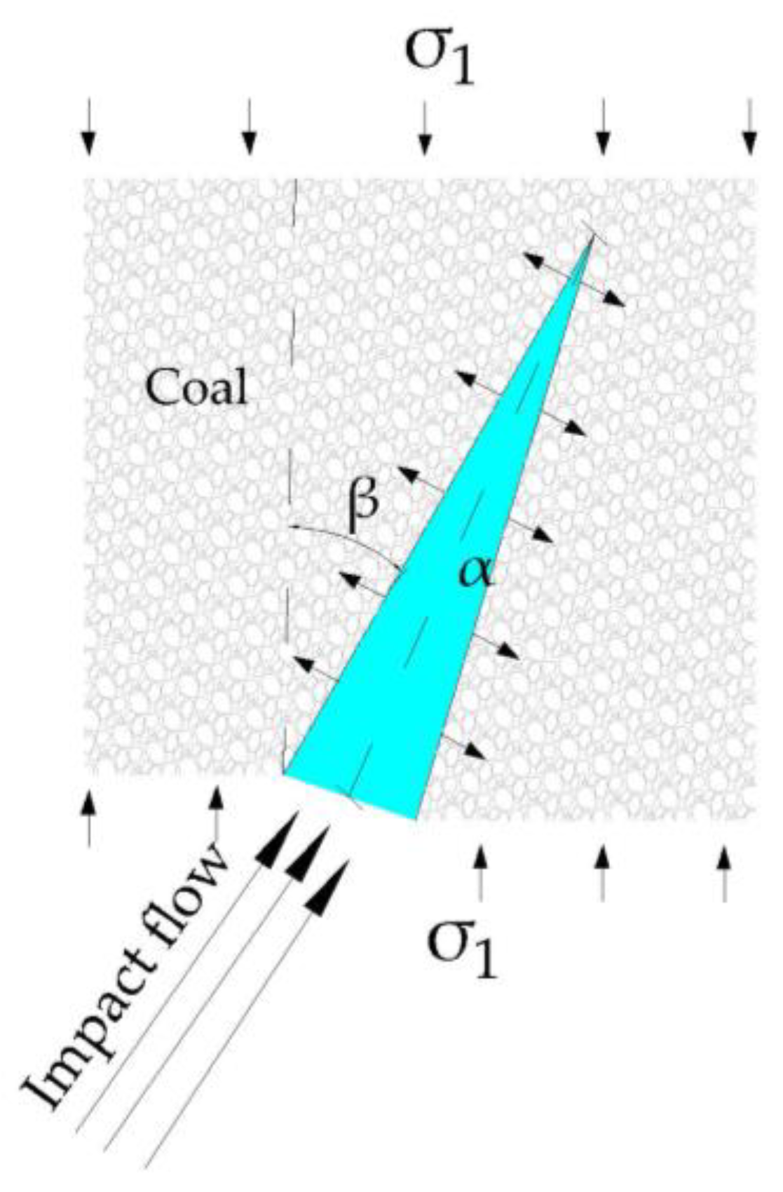
The coal is affected by the high-pressure air disturbance around the blasthole to produce radial compressive stress. Although the radial compressive stress does not cause compression damage to the coal, it becomes elastic deformation energy and is stored in the coal. The gas pressure in the explosion chamber drops as the crack propagates and the accumulated elastic deformation energy of the coal is released and forms unloading waves, under the action of which the intensity and stability of the retained coal decrease. Meanwhile, the pressure field of the coalbed methane is disturbed by external stress, and its own dynamic balance is disturbed. The coalbed methane that adsorbs in the coal seam is desorbed and then builds up with the high-pressure air accumulated at the crack’s tip to create a quasi-static stress field. The stress wave shows an exponential attenuation trend during the propagation process of the coal medium. When the propagation distance exceeds 7   r 0 and reaches the middle and far zone of blasting, the stress wave no longer drives the crack propagation, but the energy it carries produces the micro-cracks randomly distributed inside the coal. However, the combined impacts of in situ stress and the quasi-static stress field cause the stress intensity factor to rise once more near to the microcrack tip. When it approaches the dynamic fracture toughness of the retained coal, the crack propagates, as depicted in Figure 8. The formula for calculating the stress intensity factor is [31,32]:
K I 2 = 2 π a ( P b sin β - σ 1 ) · sin β 2 b π a tg π a 2 b
In the formula, β is the angle between the crack and the vertical direction.
The crack propagation rate is governed by the rise in the stress intensity factor at the crack tip. In the vicinity of blasting, after the high-pressure air wedges into the initial crack, strong air pressure and a stress wave cause the stress intensity factor   K I at the crack tip to rise. The critical value for fracture propagation is reached when the stress intensity factor surpasses it, which drives the crack to quickly propagate. In the middle and far zones of blasting, with the decrease in crack air pressure and the weakening of stress wave attenuation, the stress intensity factor at the tip of the crack slowly increases and the crack propagation slows. However, the crack still intersects with surrounding cracks to form longitudinal macro cracks. The mechanical properties deteriorate as the created macroscopic cracks increase, which eventually causes the coal to fracture.

4.2. Damage Fracture Model with the Nozzle Located in the Middle-Lower Part

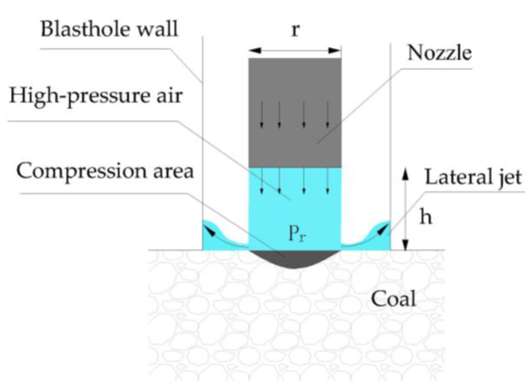
When the nozzle is in the middle-lower part of the blasthole, the jet diffusion angle basically remains the same due to the small jet diffusion angle. The bottom of the hole is nearly vertically impacted by the high-pressure air, and the area of the impacted hole bottom is equivalent to that of the size of the nozzle. The shortening of the jet distance also leads to a decrease in the energy exchange between the jet impact surface and the lower air, and between the jet boundary on both sides and the surrounding air. A small amount of energy exchange leads to a decrease in the attenuation of the jet velocity so that the impact bottom load is strong. According to rock standard classification, coal can be categorized as a soft rock with a lower compressive strength than ordinary rocks since it is a complex organic rock developed through mineralization and humification with mature inner fractures [8]. The compressive stress   σ r   in the impact area is quite high due to the small impact range and the strong load of the high-pressure air impacting the bottom of the hole. When the strength of the impact load is more than the critical compressive value   σ s of the coal mass, the structure of the coal mass will be damaged, as shown in Figure 9.
The compressive stress forms in this region when high-pressure air impacts the bottom of the hole, and the following is assumed while calculating its compressive stress: (1) The surface of the coal is smooth and horizontal when high-pressure air impacts it; no elastic deformation takes place. (2) The area where the high-pressure air impacts the bottom of the hole is the same as that of the nozzle. (3) The speed of the gas in the same segment is the same when the high-pressure air impacts the bottom of the hole. Through the above assumptions, the compressive stress generated by the impact of high-pressure air on the bottom of the hole can be obtained [33,34], which is shown below:
σ c = P b S
P b = ρ e Q V m
Q = S P K k M Z R T 1 2 ( k + 1 k + 1 k 1
V m = 8.8 r h V 0
V 0 = m m - 1 · p e ρ e 1   - p 0 ρ 0 m m - 1
In the formula:   σ c is the compressive stress generated by the high-pressure air impacting the bottom of the hole, N/m2; S is the area of the nozzle, m2; Q is the flow rate of the high-pressure air, m 3 / s ;   V m is the velocity when the high-pressure air impacts the coal,   m / s ;   V 0   is the initial velocity of the high-pressure air jet, m / s ; P is the pressure of the combined fluid during jet flow, MPa; K is the gas jet coefficient; M is the gas molar mass, kg/mol; Z is the compressibility factor; R is the molar gas constant, mol · K ;   T 1 is the gas temperature of the cracking unit, K; k is heat capacity ratio, k = ( i + 2 ) / i ; r is the diameter of the nozzle, m2;   h is the vertical distance from the nozzle to the coal surface, m; m   is the ratio of the specific heat capacity of the gas at constant volume to constant pressure;   p e is the pressure of high-pressure air injection, MPa;   ρ e   is the density of high-pressure air, kg/ m 3 ;   p 0   is the air pressure inside the blasthole, MPa;   ρ 0 is the air density inside the blasthole, kg/ m 3 .
Whether the compressive stress formed by the high-pressure air reaches the compressive strength of the coal structure mainly depends on the impact load and the area of the nozzle. It can be known from formula (13) that when the density and flow rate of the impinging airflow are constant, the load formed at the bottom of the hole under the impact of high-pressure air is proportional to the impact velocity. The impact on the bottom increases faster as the distance of the jet becomes smaller. When the distance between the nozzle and the orifice is 250 mm, the compression caused by the impact of high-pressure air at the bottom of the hole reaches the dynamic compressive strength of the coal, and the coal undergoes compression damage.
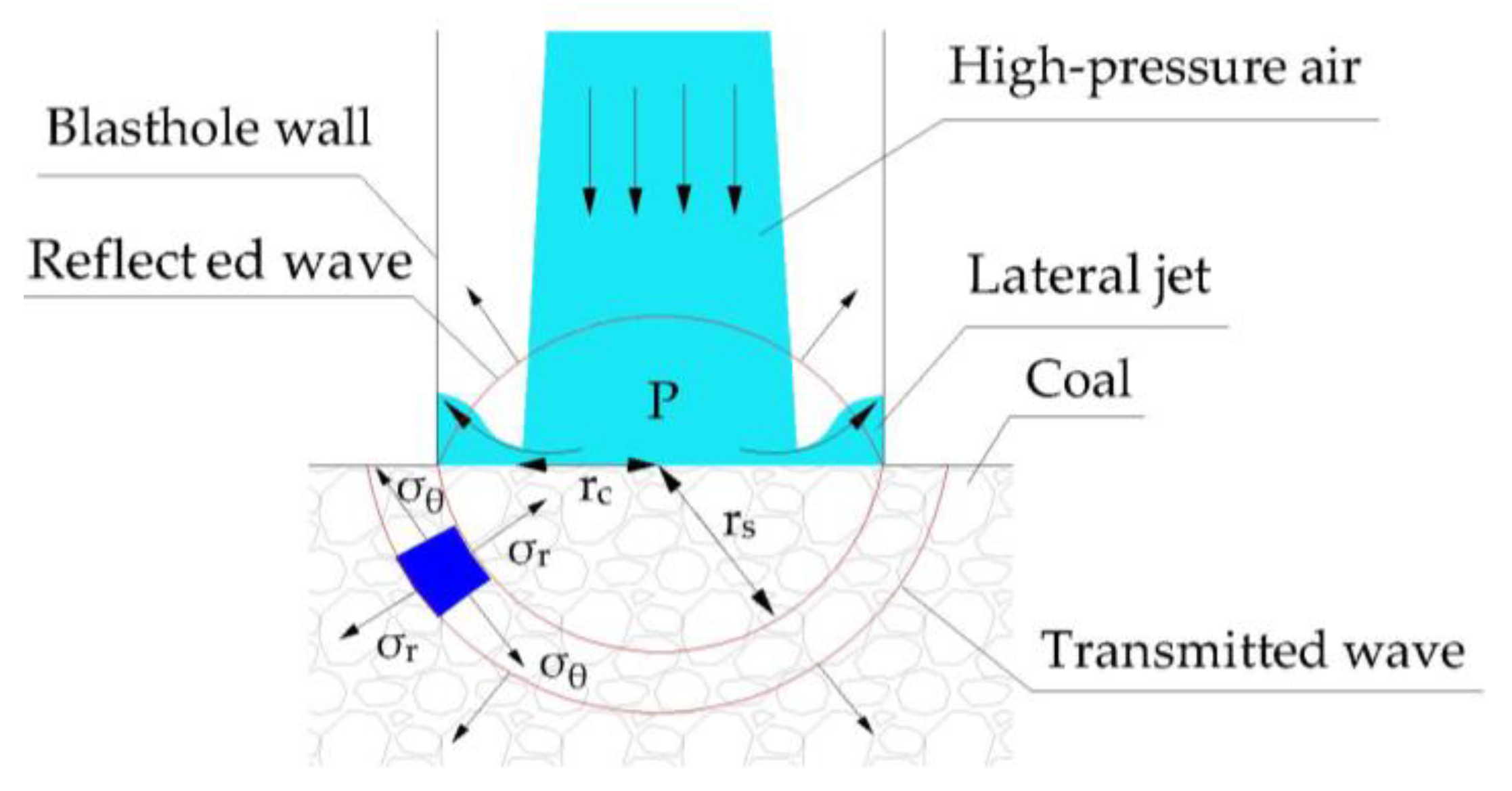
When the high-pressure air impacts the surface of the coal, there is no compression failure at the bottom of the hole. Since the wave impedance of the propagation medium changes, a reflected wave and a transmitted wave are formed at the interface at the bottom of the hole. Depending on the way the high-pressure air impacts the bottom of the hole and how the internal coal stress changes, the coal damage fracture model of the nozzle in the middle-lower part of the blasthole can be established, as shown in Figure 10.
The research direction between the concentration difference between any point on the horizontal axis of the section and the surrounding air Δ ρ m and the density difference between the initial high-pressure air and the surrounding air Δ ρ 0 have the following relationship.
Δ ρ 0 Δ ρ m = 0.7 d r + 0.3
In the formula: d represents the distance between a point on the horizontal axis and the nozzle, m.
The following relationship exists between the jet pressure P , gas density ρ , and flow sound velocity c 0 under isentropic conditions:
P   -   ρ 0 = c 0 2 ρ 0 2 ( 1 ρ 0   - 1 ρ )
From Formulas (17) and (18), the jet pressure   P r   formed on the coal surface under the impact of high-pressure air can be reached through the following formula:
P r = p 0 + c 0 2 ρ 0 0.7 Δ ρ 0 r 0.7 Δ ρ 0 r + ρ 0 ( k h + 0.3 r )
In the elastic range, the impact load has the following relationship with the dynamic stress [35]:
σ r = P r 2 ( 1 - ν ) 1 + ( 1 - 2 ν ) r c 2 r s 2
σ θ = P r 2 ( 1 - ν ) 1 - ( 1 - 2 ν ) r c 2 r s 2
In the formula,   r c is the radius of action of the jet impact pressure, mm;   r s is the distance between the position where the stress wave reaches and the center of the sphere, mm; ν is the elastic modulus of the coal.
It can be known from Formulas (20) and (21) that high-pressure air is accompanied by a large amount of dynamic impact energy when it flows at high speed. When it impacts the bottom of the hole, the airflow acts on the bottom of the hole in the form of pressure, and the bottom hole of the lower coal is disturbed to generate tensile stress, as shown in Figure 10. Due to the great difference in the density of the medium on both sides of the interface when the high-pressure air impacts the bottom hole, the reflection of the shock wave at the upper part of the hole bottom is greater, and the corner position of the hole bottom is subjected to stronger tensile stress. When the tensile stress reaches the dynamic tensile strength of the coal, the bottom corner of the hole first cracks along the horizontal direction and evolves into a horizontal initial crack.
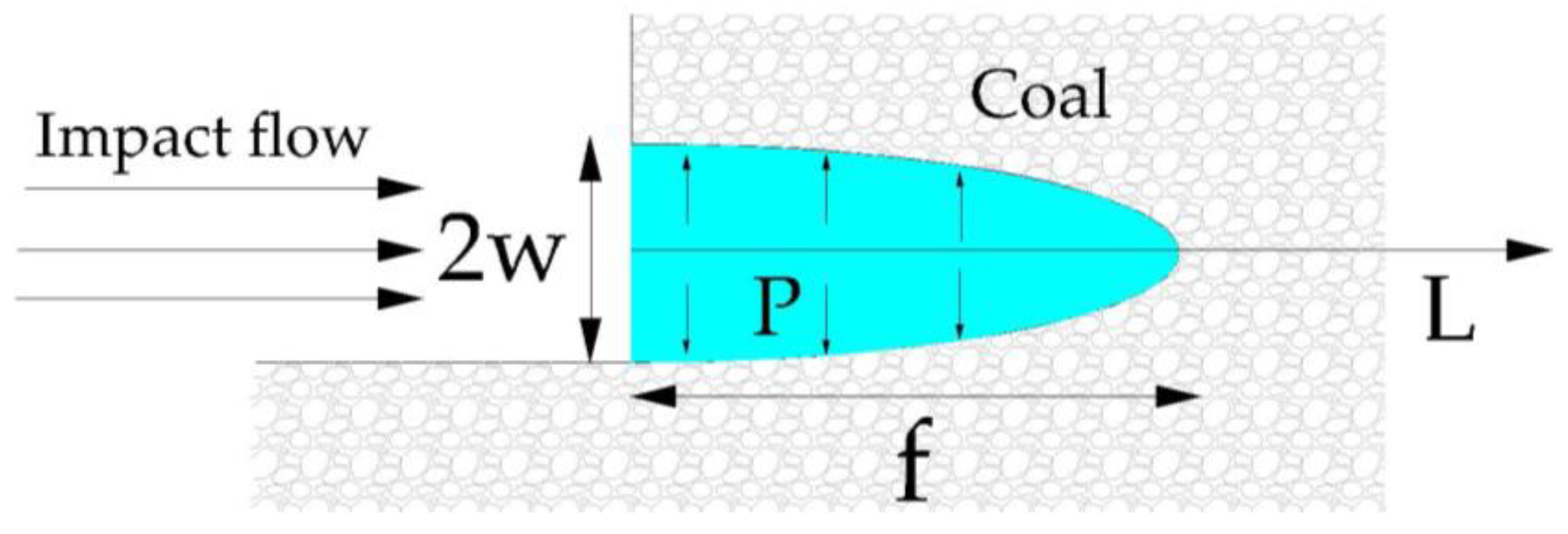
A lateral jet is generated when the airflow rapidly diffuses around the impact boundary. When it impacts the bottom corner of the hole, some of the gas wedges into the initial crack there, driving it to extend in length and width. To obtain the relationship between the air pressure at the crack section and the length and width of the horizontal crack extension, the following assumptions are made: (1) The crack’s horizontal part has a semi-elliptical shape. (2) The plane of the coal is a semi-infinite body. (3) The air pressure on the crack section is uniform. As shown in Figure 11. The relationship between the gas pressure and the length and width of crack propagation can be obtained, which is shown according to the following formula:
  P b   = w π E 4 1 - μ 2 ( f - L )
In the formula,   w is half of the crack width,   L is the crack length, E is the elastic modulus of the coal, and f is the major semi-axis of the elliptical crack.
When the side jet collides with the hole’s roof along the hole wall, the jet’s course changes once more. The hole vertices develop horizontal initial cracks as a result of the combined action of stress concentration and tensile tension. However, due to the weakening of the disturbance at the top by the impact of the airflow, and the prominent effect of the confining pressure loaded on the crack propagation, the horizontal crack at the top corner of the hole presents a wavy shape and the crack section is rougher. The high-pressure air impacts the top of the hole first, then builds up and expands inside the hole, forming an expansion wave that impacts the hole wall.
In the middle and far areas of blasting, the gas adsorbed on the coal seam loses balance, desorbs, and merges into high-pressure air and gathers together at the tip of the crack to form a quasi-static stress field. Under the joint action of the quasi-static stress field and original rock stress, the horizontal cracks at both ends of the blasthole and the longitudinal cracks around the hole wall continue to propagate and intersect, forming macroscopic cracks that run through the coal. The stress wave disturbs the medium surrounding the hole wall, causing longitudinal cracks to form and propagate. However, the horizontal cracks formed at both ends of the blasthole weaken the propagation ability of the longitudinal cracks in the coal, which causes the formation of longitudinal cracks only in the depth range of the blasthole. The formation of horizontal and longitudinal cracks leads to a decrease in the ability of the retained coal mass to resist deformation, which accelerates the fracture of the coal mass. Due to the action of a small amount of gas and a weaker stress wave, the initial crack of the bottom is hard to form and the original crack no longer propagates. Therefore, the bottom of the hole is no longer damaged.

5. Conclusions

As an important green energy, coalbed methane is often adsorbed in low-permeability coal seams and is difficult to exploit. The use of blasting technology to improve the fracture properties of coal rocks (including density, cutting depth, etc.) is the key factor to improve the exploitation of coalbed methane. In this paper, based on the actual problems in the coalbed methane mining process, a simulation test study was carried out, and a corresponding damage and fracture model was established, and the reliability of the model was verified in subsequent tests. By analyzing different damage fracture models, the following conclusions can be drawn:
  • When the nozzle is located in the upper part of the blasthole, longitudinal cracks penetrating the coal are formed at the upper and lower parts of the hole bottom. The crack slice depth is deeper. Meanwhile, under the action of the stress wave, many short and narrow secondary cracks in different directions are formed, and coal crack density increases. The increase in cutting depth and crack density improves the permeability of the coal seam, which is more conducive to the production of coalbed methane.
  • When the nozzle is located in the middle-lower part of the blasthole, the bottom and top of the hole form a horizontal crack run through the coal under the superposition of stress concentration and tensile stress. Longitudinal cracks are only formed within the depth range of the blasthole. The crack density is small, and the cutting depth is limited to the upper part of the hole bottom. The permeability of the coal in the lower part of the hole bottom is not improved. The coal bed methane extraction volume is not as good as the nozzle located in the middle-upper part.
  • When the nozzle position is close to the bottom of the hole, the enormous impact load will cause the bottom of the hole to be crushed and destroyed. This causes energy dissipation and weakens the ability of crack propagation, making the density and tangential depth of crack propagation in coal far less than the above two positions. Coalbed methane extraction is the lowest.
  • By comparing the results, it was found that when the nozzle is located in the middle-upper part of the blasthole, the crack grid formed by the coal is more complex. When the nozzle is in the middle-lower part of the blasthole, horizontal cracks are easy to form at the bottom and top of the hole, and the crack propagation direction is single, so a three-dimensional crack grid cannot be formed. Therefore, the production of coalbed methane extracted from nozzles located in different positions is in the order from high to low: the middle-upper part, the middle-lower part, and the bottom part.
In this study, based on the test results, a damage fracture model with nozzles located at different positions was established, and the influence of nozzle positions on coal crack propagation and coalbed methane extraction was analyzed through theoretical analysis. This is only a preliminary study. In future experimental research, based on this study, we can study in detail the specific influence of nozzle position on crack propagation density and crack depth. By calculating the density and tangential depth of cracks, the influence of nozzle position on the coalbed methane recovery rate is introduced in detail.

Author Contributions

For conceptualization, H.C., D.W. and X.Y.; methodology, D.W. and H.C.; formal analysis, D.W.; investigation, M.Y., B.S., S.Y., G.Z. and J.X.; writing—original draft preparation, D.W.; writing—review and editing, H.C. and X.Y.; visualization, H.C. and D.W. All authors have read and agreed to the published version of the manuscript.

Funding

This work was funded by the National Natural Science Foundation of China (No. 52130403), National Natural Science Foundation of China (No. 50874039).

Institutional Review Board Statement

Not applicable.

Informed Consent Statement

Not applicable.

Data Availability Statement

All data in the article are derived from real experimental designs and results that have been presented in the article.

Acknowledgments

The author thanks Chang Wang for providing the basis for this experimental research, and thanks the reviewers for reading the article in their busy schedule and providing valuable opinions.

Conflicts of Interest

The authors declare no conflict of interest.

References

  1. Liu, Y.; Zhang, S.; Shu, L. Coalbed methane migration mechanism under adsorption-desorption condition in coal. Coal Geol. Explor. 2019, 47, 12–18. [Google Scholar] [CrossRef]
  2. Hu, L.; Feng, Z.; Zhou, D.; Wang, X.; Shi, J.; Shen, Y.; Zhao, D. Numerical simulation study and engineering practice of in-situ heat injection mining of coalbed methane. J. China Coal Soc. 2023, 1–14. [Google Scholar] [CrossRef]
  3. Chu, H.B.; Wang, C.; Yang, X.L.; Yan, S.Y.; Ren, Y.Q.; Chen, Z.; Zhu, S.Y. A simulation experimental study on high-pressure air blasting of coal. J. Vib. Shock 2022, 41, 54–60+157. [Google Scholar] [CrossRef]
  4. Sun, H.T.; Shu, L.Y.; Jiang, Z.B.; Hu, J. Progress and trend of key technologies of CBM development and utilization in China coal mine areas. Coal Sci. Technol. 2022, 50, 1–13. [Google Scholar] [CrossRef]
  5. Yang, R.; Cong, R.; Liu, H.; Huang, Z.; Wen, H.; Hong, C. Pore-scale analysis of coal structure and mechanical properties evolution through liquid nitrogen thermal shock. Nat. Gas Ind. 2021, 41, 82–92. [Google Scholar] [CrossRef]
  6. Gao, J.L.; Guan, C.H.; Zhang, B. China’s CH4 emissions from coal mining: A review of current bottom-up inventories. Sci. Total Environ. 2020, 725, 2–7. [Google Scholar] [CrossRef]
  7. Liu, S.Q.; Wang, H.; Sang, S.X.; Hu, Q.J.; Jia, H.M.; Mao, C.H. Phase change and mass transfer process of coalbed water in anthracite res-ervoir and its engineering inspiration for coalbed methane development. J. China Coal Soc. 2023, 1–14. [Google Scholar] [CrossRef]
  8. Chu, H.B.; Yiao, X.L.; Wang, C.; Liang, W. Study on the Coal damage fracture Mechanism under Multiple Actions of Blasting Stress Wave. Arab. J. Sci. Eng. 2021, 46, 10847–10854. [Google Scholar] [CrossRef]
  9. Zhao, D.; Wang, M.Y.; Gao, X.H. Study on the technology of enhancing permeability by deep hole presplitting blasting in Sanyuan coal mine. Sci. Rep. 2021, 11, 20353. [Google Scholar] [CrossRef]
  10. Ti, Z.; Zhang, F.; Pan, J.; Ma, X.; Shang, Z. Permeability enhancement of deep hole pre-splitting blasting in the low permeability coal seam of the Nanting coal mine. PLoS ONE 2018, 13, e0199835. [Google Scholar] [CrossRef]
  11. Shipovskii, I.; Odintsev, V. Numerical simulation of the stress-strain state of a coal seam caused by an explosion of a blast-hole charge with an annular gap. EPJ Web Conf. 2019, 221, 01053. [Google Scholar] [CrossRef] [Green Version]
  12. Hu, Q.T.; Liu, L.; Li, Q.G.; Wu, Y.Q.; Wang, X.G.; Jiang, Z.Z.; Yan, F.Z.; Xu, Y.C.; Wu, X.B. Experimental investigation on crack competitive extension during hydraulic fracturing in coal measures strata. Fuel 2020, 265, 117003. [Google Scholar] [CrossRef]
  13. Xu, J.Z.; Zhai, C.; Pathegama, G.R.; Sang, S.X.; Sun, Y.; Cong, Y.Z.; Tang, W.; Zheng, Y.F. Investigation of the mechanical damage of low rank coals under the impacts of cyclical liquid CO2 for coalbed methane recovery. Energy 2022, 239, 122145. [Google Scholar] [CrossRef]
  14. Sampath, K.H.S.M.; Perera, M.S.A.; Ranjith, P.G.; Matthai, S.K.; Li, D. Qualitative and quantitative evaluation of the alteration of micro-fracture characteristics of supercritical CO2-interacted coal. J. Supercrit. Fluids 2019, 147, 90–101. [Google Scholar] [CrossRef]
  15. Cao, Y.; Zhang, X.; Zhang, J.; Guo, S.; Meng, B. Characteristics and formation mechanisms of microstructures incoal treated with CO2 phase transition fracturing. Coal Geol. Explor. 2023, 51, 137–145. [Google Scholar] [CrossRef]
  16. Trofimov, V.A.; Shipovskii, I.E. Computer modeling of coal seam blasting. J. Min. Sci. 2020, 56, 741–752. [Google Scholar] [CrossRef]
  17. Huang, Z.W.; Li, G.F.; Yang, R.Y.; Li, G.S. Review and development trends of coalbed methane exploitation technology in China. J. China Coal Soc. 2022, 47, 3212–3238. [Google Scholar] [CrossRef]
  18. Zhang, S.A.; Liu, X.Z.; Wen, Q.Z.; Xiao, Z.; Wei, Z.; Yu, Y. Development situation and trend of stimulation and reforming technology of coalbed methane. Acta Pet. Sin. 2021, 42, 105–118. [Google Scholar]
  19. Chen, H.H.; Fan, H.F.; Guo, J.P.; He, X. Analysis and prospect on hydraulic fracturing fluid used in coalbed methane well. Coal Geol. Explor. 2017, 45, 33–40. [Google Scholar] [CrossRef]
  20. Xu, F.Y.; Yan, X.; Lin, Z.P.; Li, S.; Xiong, X.; Yan, D.; Mei, Y. Research progress and development direction of key technologies for efficient coalbed methane development in China. Coal Geol. Explor. 2022, 50, 1–15. [Google Scholar]
  21. Yan, S.Y.; Yang, X.L.; Chu, H.B.; Wang, C. Experimental Study on the Dynamic Response and Pore Structure Evolution of Coal under High-Pressure Air Blasting. ACS Omega 2022, 7, 24475–24480. [Google Scholar] [CrossRef]
  22. Li, S.G. Key technology and equipment research and development of improving coal seam permeability by high-pressure air blasting. Coal Sci. Technol. 2015, 43, 92–95. [Google Scholar] [CrossRef]
  23. Yang, X.L.; Wang, C.; Chu, H.B.; Yan, S.Y.; Wei, H.X.; Yu, M.F. Study on the Stress Field and Crack Propagation of Coal Mass Induced by High-Pressure Air Blasting. Mianerals 2022, 12, 300. [Google Scholar] [CrossRef]
  24. Saeed, A.; Najm, H.M.; Hassan, A.; Sabri, M.M.S.; Qaidi, S.; Mashaan, N.S.; Ansari, K. Properties and Applications of Geopolymer Composites: A Review Study of Mechanical and Microstructural Properties. Materials 2022, 15, 8250. [Google Scholar] [CrossRef]
  25. Chen, M.; Huang, H.J.; Wang, D.Y.; Lee, S.; Chen, Y. PIV tests for flow characteristics of impinging jet in a semi-closed circular pipe. J. Vib. Shock 2021, 40, 91–97. [Google Scholar] [CrossRef]
  26. Qaidi, S.; Najm, H.M.; Abed, S.M.; Özkılıç, Y.O.; Al Dughaishi, H.; Alosta, M.; Sabri, M.M.S.; Alkhatib, F.; Milad, A. Concrete Containing Waste Glass as an Environmentally Friendly Aggregate: A Review on Fresh and Mechanical Characteristics. Materials 2022, 15, 6222. [Google Scholar] [CrossRef]
  27. Yin, G.Z.; Wang, D.K. A coupled elastoplastic damage model for gas-saturated coal. Chin. Rock Mechan. Eng. 2009, 28, 993–999. [Google Scholar]
  28. Gou, Y.G.; Shi, X.Z.; Qiu, X.Y.; Zhou, J.; Chen, H.; Huo, X. Propagation Characteristics of Blast-Induced Vibration in Parallel Jointed Rock Mass. ASVE 2019, 19, 14. [Google Scholar] [CrossRef]
  29. Zhang, Z.X.; Kou, S.Q.; Lindqvist, P.A.; Yu, Y. The relationship between the fracture toughness and tensile strength of rock. In Strength Theories: Applications, Development & Prospects for 21st Century; Science Press: Beijing, China, 1998; pp. 215–219. [Google Scholar]
  30. Chu, H.; Yu, M.; Sun, B.; Yan, S.; Wei, H.; Zhang, G.; Wang, D.; Xu, J. Experimental Study on Damage Fracture Law of Coal from Solid-Propellant Blasting. Energies 2022, 15, 8104. [Google Scholar] [CrossRef]
  31. Murakami, Y. Stress Intensity Factors Handbook; Pergamon Press: Oxford, UK, 1987. [Google Scholar]
  32. Yang, X.; Wang, S. Meso-mechanism of damage and fracture on rock blasting. Explos. Shock Waves 2000, 20, 247–252. [Google Scholar]
  33. Zhang, D.M.; Bai, X.; Yin, G.Z.; Li, S.J.; Rao, Z.; He, Q.B. Mechanism of breaking and fracture expansion of liquid CO2 phase change jet fracturing in low-permeability coal seam. J. China Coal Soc. 2018, 43, 3154–3168. [Google Scholar] [CrossRef]
  34. Peng, S.N.; Zhou, Y.H. Discussion On Models for Gas Leakage And Diffusion. Gas Heat 2008, 28, 39–42. [Google Scholar]
  35. Liu, S.; Du, C.; Jiang, H. Mechanical-Water Jet Combined Rock Breaking and Its Application in Mining Machinery; Science Press: Beijing, China, 2017. [Google Scholar]
Figure 1. Schematic diagram.
Sustainability 15 11171 g001
Figure 2. High-pressure air bursting test system. (a) Schematic diagram of high-pressure air bursting test system. (b) Physical object diagram of high-pressure air bursting test system.
Sustainability 15 11171 g002
Figure 3. Simulation of coal production and test. (a) Reserved blasthole. (b) Blasthole seal. (c) High-pressure air blasting test.
Sustainability 15 11171 g003
Figure 4. Test results of the nozzle in the middle-upper part. (a) Top view of blasting simulation coal. (b) Side view of blasting simulation coal.
Sustainability 15 11171 g004
Figure 5. Test results of the nozzle at middle-lower parts. (a) Side view of blasting simulation coal. (b) Internal crack propagation of blasting simulation coal.
Sustainability 15 11171 g005
Figure 6. The nozzle is located in the middle-upper impact schematic.
Sustainability 15 11171 g006
Figure 7. The nozzle is located in the middle-upper damage fracture model.
Sustainability 15 11171 g007
Figure 8. Crack tip stress intensity factor.
Sustainability 15 11171 g008
Figure 9. The bottom of the hole compression damage model.
Sustainability 15 11171 g009
Figure 10. The nozzle is located in the middle-lower damage fracture model.
Sustainability 15 11171 g010
Figure 11. Horizontal crack expansion model at the bottom of the hole.
Sustainability 15 11171 g011
Table 1. Hard coal basic physical and mechanical parameters.
ParameterValueParameterValue
Density (g·cm−3)1.4–1.6P wave velocity (m·s−1)1800–2000
Compressive strength (MPa)12–18Elastic modulus (GPa)2.3–3.2
Tensile strength (MPa)0.8–2Poisson’s ratio0.2–0.3
Table 2. Simulation of coal briquette material proportioning.
MaterialQuantity (kg)MaterialQuantity (kg)MaterialQuantity (kg)
Sand6.500Gypsum0.333Perlite0.045
Cement2.333Foaming agent0.080
Water1.000Crushed mica0.047
Table 3. Simulation of coal basic physical and mechanical parameters.
ParameterValueParameterValue
Density (g·cm−3)1.62P wave velocity (m·s−1)2046
Compressive strength (MPa)13.46Elastic modulus (GPa)2.70
Tensile strength (MPa)1.39Poisson’s ratio0.29
Disclaimer/Publisher’s Note: The statements, opinions and data contained in all publications are solely those of the individual author(s) and contributor(s) and not of MDPI and/or the editor(s). MDPI and/or the editor(s) disclaim responsibility for any injury to people or property resulting from any ideas, methods, instructions or products referred to in the content.