Article

Comparative Analysis of Hotspot Stress Endurance in Pristine and Thermal Cycled Prestressed Glass–Glass Photovoltaic Modules

Photovoltaic Reliability Laboratory, Arizona State University, Mesa, AZ 85212, USA
*
Author to whom correspondence should be addressed.
Sustainability 2023, 15(16), 12131; https://doi.org/10.3390/su151612131
Submission received: 7 July 2023 / Revised: 6 August 2023 / Accepted: 7 August 2023 / Published: 8 August 2023

Abstract

:
Hotspots pose a significant long-term reliability challenge in photovoltaic (PV) modules that can have a detrimental impact on the efficiency, safety, and financial viability of a PV system. This paper aims to evaluate the endurance of hotspot stress in pristine and prestressed glass–glass (GG) modules. The accelerated prestressing was conducted for 600 thermal cycles (TC600) to represent decades of field exposure. GG modules are quickly becoming an alternative to the traditional glass–backsheet (GB) modules that have been the industry standard. Unlike other conventional studies that subject only pristine modules to hotspot stress, this paper evaluates the performance of an accelerated/simulated field-aged GG module (using TC600) and a pristine GG module. Pre- and post-characterizations were performed before and after each test to determine changes in electrical performance and observe any defects in GG modules. During the hotspot test, an approximately 200 °C maximum cell temperature was observed with a cell shading of 25% (the worst-case shading ratio). After the hotspot test, electroluminescence imaging indicated that most cells in the prestressed GG module exhibited severe damage whereas no significant defects were evident in the pristine GG module where the prestressed GG module degraded 8.2% and the pristine GG module degraded 1.5% in maximum power. These findings are critical for the industry, considering that GG bifacial modules will dominate the market.

1. Introduction

Advancements in the design of crystalline silicon (c-Si) PV modules, along with the economies of scale, have been continuously reducing the electricity cost of PV while enhancing its reliability [1]. Glass–glass (GG) PV module designs are a promising option for PV power systems due to their superior performance and durability [2]. Compared to traditional glass–backsheet (GB) modules, GG modules have a double glass structure [3], having glass on both (front and rear) sides of the module, which enhances mechanical strength and makes the cells and module less susceptible to damage from weather and environmental conditions [4]. GG modules are reported to offer a number of advantages over traditional GB modules, as well as a longer lifespan [2].
One of the main advantages of GG modules is claimed to be their increased durability due to better resistance to mechanical stresses than GB modules [5,6]. These modules are reported to be more resistant to environmental factors such as humidity and temperature changes [5,6] and offer increased energy production [5]. Some studies have shown that the use of glass on both sides of the module reduces light-induced degradation, leading to better long-term performance [7]. GG modules have a higher transparency than traditional modules, allowing for more sunlight to pass through to the solar cells [8]. GG modules are also claimed to improve the aesthetics of a PV system [9], creating a professional look that is particularly desirable for residential or commercial applications [10]. Additionally, the use of glass on both sides of the module can increase the viewing angle of the solar cells, making the modules more effective at capturing sunlight at different times of the day [11] and providing better environmental protection to the solar cells with a longer anticipated lifetime [2]. Additionally, GG modules are reported to have a lower degradation rate [6,12] compared to traditional modules, which is expected to result in higher energy output over the service life of the system [12].
It is expected that bifacial modules will increase their market share from 15% in 2019 to 70% by 2030 [1]. To meet the growing demand, it is essential to study the reliability and safety of these new GG designs. Multiple environmental stressors that coexist in actual field conditions can drastically affect the reliability of PV modules, which can result in several defects, eventually leading to electrical power degradation in the module [13]. To quickly obtain degradation data, accelerated testing methods (like thermal cycling of the module) are employed to assess the performance of PV modules [14] since actual degradation that occurs during field-use operation requires a significant amount of time to become apparent [15].
The hotspot effect is a major concern for the long-term reliability and safety of c-Si modules that have been operating in the field for an extended period [16,17]. Hotspots refer to specific localized areas in PV modules where the temperature increases to such extreme levels that it can cause damage to the solar cells as well as other components of the module [18,19]. Hotspots occur when a PV module, for example, is partially shaded [20] while the rest of the module remains exposed to sunlight. Even minimal shading can result in a decrease in the output power of the PV module. During this time, the shaded cells generate less current as compared to the modules’ operational electrical current [19]. This can cause the voltage of the underperforming cell to reverse and become opposite but equal to the rest of the solar cells connected in series. This creates hotspots, where the defective or shaded cell places an excessive load on the other cells in the series, leading to the dissipation of a significant amount of energy as heat [21]. This excess heat can cause various issues, such as the melting of the solder or the development of cell cracks and can even cause the encapsulant to degrade [22]. The development of hotspots can also result from mismatches occurring between the solar cells, which can also develop due to irregular sorting of solar cells or due to breakage in the cell interconnections [23].
Hotspots can lead to the degradation of the PV module’s performance and, in severe cases, can cause fire accidents due to the combustible material of PV modules [16]. Using diagnostic techniques like thermal imaging and electroluminescence imaging, Wang and Xuan [24] thoroughly investigates hotspot formation in PV modules and offers detailed insights into hotspot behavior and its impact on PV performance and longevity. Results reveal hotspots are not uniform and are influenced by each cell’s local conditions, whereas [25] proposes using microinverters and power optimizers [26] to control electric current and prevent hotspots in PV systems. Their approach exhibits potential for enhancing system performance and longevity. Experimental results validate the efficacy of this solution. Similarly, Khodapanah et al. [27] presents a novel method for detecting shading and predicting hotspots using the numerical differentiation and integration of power–voltage curves and offers an innovative solution for timely hotspot detection. Furthermore, Chen et al. [28] employs machine learning for hotspot detection in PV systems. By leveraging current-voltage characteristics, temperature profiles, and more, their model can predict hotspot formation in real-time. This innovative approach marks a shift from traditional techniques, improving efficiency and maintenance.
Hotspots can impact module performance in large-scale grid-connected PV power systems. Hence, several mitigation strategies, including bypass diodes, shading avoidance, and effective cooling systems, have been suggested and used [29]. Despite efforts to incorporate auxiliary protection circuitry at the module level [30,31,32], the hotspot effect remains a common occurrence [22]. The output performance of a PV system that had been functional for over ten years was evaluated, where the hotspot effect played a significant role in the loss of output power [33]. Additionally, an investigation of the impact of thermal degradation discovered the presence of hotspots in modules that had been operating in the field for more than 18 years, as opposed to newly installed modules [34]. Shading or cell mismatch of PV modules can result in hotspots, which can result in a significant reduction in the module’s performance [35], affecting its electrical characteristics, which can result in decreased output power generation [36]. New methods for detecting hotspots in PV modules using machine learning algorithms have been proposed where such techniques can potentially detect hotspots, allowing for early detection and mitigation [37,38].
The objective of this study is to evaluate the endurance of hotspot stress of pristine and prestressed (with thermal cycling) GG modules. In this investigation, using a thermally cycled GG module enables a close approximation of field-stressed modules experiencing the hotspot stress in actual field-use conditions. To simulate more than 20 years of field operation, a GG module underwent prestressing through 600 accelerated thermal cycles. This study introduces an innovative approach, where we evaluate the hotspot endurance of a pristine module along with a prestressed (with thermal cycling) module simulating hotspot evaluation of a field-aged GG module, unlike the IEC 61215 standard [39] and other conventional studies that subject only pristine modules to hotspot endurance stress. It is important to recognize that the findings and test results presented in this study may not be confidently generalized for all types of GG modules as this study does not involve a statistically significant number of GG modules. Hence, it is possible that factors other than the superstrate and substrate materials, such as the manufacturer’s quality control or distinct bill of materials, may influence the test results.

2. Methodology

In this paper, the GG modules stressed for hotspot endurance consist of seventy-two 156.75 mm bifacial full-cells in a series configuration and were acquired from the same manufacturer via the open market. These modules are frameless and measure 1991 mm × 989 mm × 7 mm, with a weight of 33.5 kg. Additionally, these modules consist of monocrystalline-type passivated emitter rear contact cells (PERC). The front and back glass thickness for these modules is 3.2 mm, having EVA as an encapsulant. The EL images were collected with the help of a silicon-based charge-coupled device (Si-CCD) EL camera in a dark room. During the EL imaging technique, the modules were subjected to an electrical current that was equal to its short-circuit current (Isc) value. An exposure duration of sixty seconds was used to capture the module EL images. In addition, the light current–voltage (I-V) curves were measured using an I-V tracer under natural sunlight to determine the electrical parameters such as short-circuit current (Isc), open circuit voltage (Voc), peak current (Ipeak), peak voltage (Vpeak), maximum power (Pmax), and fill factor (FF).

2.1. Applying Thermal Cycling to Prestress the GG Module

The thermal cycling test was performed on GG module for 600 cycles to induce mechanisms leading to wear-out of the GG module, using an indoor environmental chamber with the ability to regulate the ambient temperature. The test was conducted according to the method outlined in the IEC 61215 standard [39] shown in Figure 1. During the thermal cycling test, the duration of each cycle was approximately five hours, which comprised of two dwell periods of 15 min each, during which the temperature of the chamber was kept at the upper and lower levels, respectively. The rate of change of temperature was one degree Celsius per minute between the highest and lowest temperature setpoints. The range of temperature during the test was kept from −40 °C to 85 °C, resulting in a cumulative temperature change of 125 °C. This significant temperature variation induced stress in the materials of the module, exceeding and accelerating what it would experience during actual field-use conditions. During this test, the module was supplied with an electrical current equivalent to the module’s Isc and was injected as the ambient temperature rose.

2.2. Performing the Hotspot Experiment

Before beginning the hotspot experiment, the measured irradiance outdoors was in the range of 1000 ± 100 W/m2 in the field, while the starting temperature for the GG modules was measured in the 50 ± 10 °C range. The hotspot testing technique described in IEC 61215 standard [39] was followed in this work. By analyzing the light I-V curves obtained outdoors in the field, where each cell was entirely shaded individually, a single solar cell with the largest shunt resistance and three individual solar cells with the lowest shunt resistance for the GG modules were identified as test cells. Solar cells exhibiting a large shunt resistance are characterized by an I-V curve that has a minimal leakage current after the bypass diode is triggered, whereas solar cells with a low shunt resistance display an I-V curve that exhibits a leakage current after the bypass diode is triggered. To determine the worst-case shadow condition and obtain the highest temperature due to hotspot heating, I-V curves were collected for the test cells while they were shaded at different ratios individually. After the identification of the worst-case shadowing scenario, the test cells were individually covered with that particular shadowing level, and the module was short-circuited for a minimum of one hour, as illustrated in Figure 2 while recording the operating temperature of the shadowed cell.
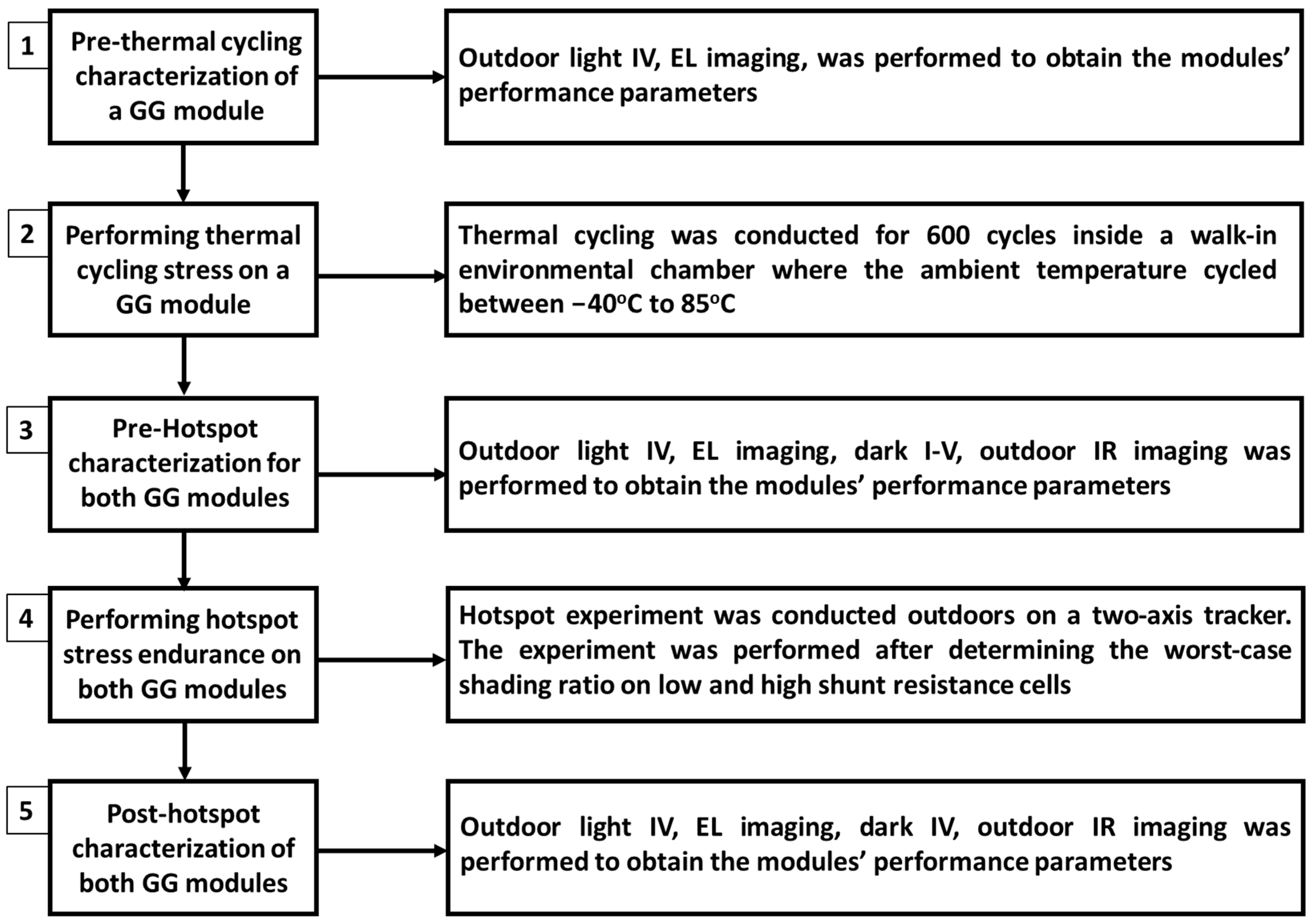
Prior to and after performing thermal cycling and the hotspot experiment, characterization of the GG modules was conducted, resulting in an experimental design having five steps (as illustrated in Figure 3). The characterization process involved measuring the I-V curves, calculating the series ‘Rs’ and shunt resistance ‘Rsh’ by determining the dark I-V, conducting EL imaging to detect any cell level defects and damage and verify any degradation in GG modules, and visually inspecting the modules.

3. Results and Discussion

Section 3.1 presents the thermal stress level experienced by the test cells in GG modules during the hotspot experiment, Section 3.2 discusses the change in EL images for GG modules and analyses the mean grayscale value pre- and post-hotspot stress test, Section 3.3 discusses the degradation in electrical parameters for GG modules, and Section 3.4 discusses the potential degradation mechanisms observed in the GG modules post-hotspot stress test.

3.1. Hotspot Experiment Temperatures for GG Modules

To collect the I-V curves for GG modules, the test solar cells were shadowed individually at a worst-case shadowing level. In both modules, the worst-case shadow condition was observed when each test cell was shaded at 25%. Under this circumstance, the value of the electrical current at the maximum power point (MPP) of the shadowed module is almost identical to the modules’ nameplate peak current (Imp). At this time, the bypass diode gets triggered at an electrical current value that is very close to the Imp of the unshaded module. All the test cells were individually subjected to a shading ratio of 25% throughout the hotspot experiment. This resulted in all the test cells experiencing high thermal stress. During the worst-case shadow condition, the shadowed cells operate as an electrical load, drawing the maximum electrical power generated by the other cells in the string instead of producing electrical power. Under such circumstances, the shadowed solar cell dissipates a tremendous amount of thermal energy and functions in reverse-bias condition.
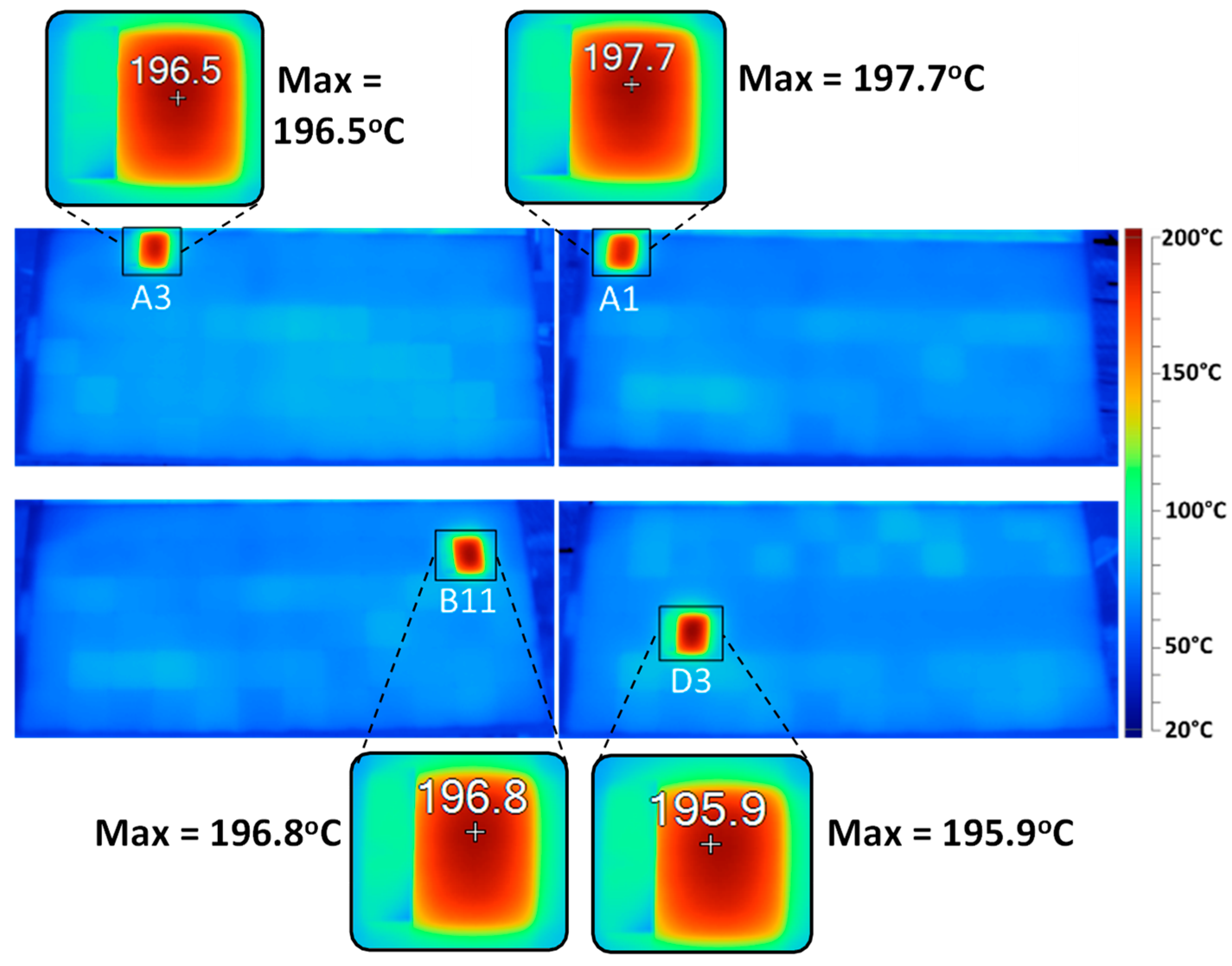
The hotspot test resulted in a considerable temperature rise in the shadowed cells due to their reverse-bias condition and the consequent heat dissipation. To monitor the shadowed cells’ temperature, a thermocouple of type-T was affixed to the backsheet of the module to record the operating temperature of the shadowed cells at periodic intervals throughout the hotspot test. A datalogger having a ±2 °C level of accuracy was employed to collect and record the temperature measurements. For the prestressed GG module, cell number A10 was chosen as the solar cell with the largest shunt resistance, and cell numbers F11, F5, and F2 were selected as the cells with the lowest shunt resistance, as shown in Figure 4. For the pristine GG module, cell number B11 was chosen as the solar cell with the largest shunt resistance, and cell numbers A3, A1, and D3 were selected as the cells with the lowest shunt resistance, as shown in Figure 5. Figure 4 and Figure 5 show that, throughout the hotspot experiment, all the test cells in the GG modules experienced almost identical peak temperatures, which indicates that these modules have an identical failure mechanism. The peak temperature of hotspots for the prestressed GG module’s cells was approximately 195 °C, whereas the highest temperature of hotspots for the pristine GG module’s cells was nearly 198 °C.
Figure 4 exhibits the infrared (IR) images demonstrating the dissipation of heat by the stressed cells numbered A10 (top left IR image), F11 (top right IR image), F5 (bottom right IR image), and F2 (bottom left IR image) in the prestressed GG module throughout the hotspot experiment. Similarly, Figure 5 exhibits the infrared (IR) images demonstrating the dissipation of heat by the stressed cells numbered A3 (top left IR image), A1 (top right IR image), D3 (bottom right IR image), and B11 (bottom left IR image), in the pristine GG module throughout the hotspot experiment. Based on the obtained IR images, it can be concluded that during the hotspot experiment, the solar cells in the GG modules endured a considerable amount of thermal stress after the solar cells were partially shadowed. A likely reason for the significant thermal stress can be attributed to the localized heating caused by the reverse flow of electrical current that occurred when the module was partially shadowed. This can be a potential cause for the power loss observed in the GG modules, which can also create a safety hazard during module handling [40] in addition to the possibility of breakage of the modules’ glass.

3.2. Analysis of EL Images Post-Hotspot Test

The performance of the GG modules was evaluated by analyzing the EL images. The EL images obtained pre- and post-hotspot test for the pristine GG module are illustrated in Figure 6, whereas the EL images obtained pre- and post-hotspot test for the prestressed GG module are illustrated in Figure 7. The pre-hotspot EL image for the pristine GG module shown in Figure 6 (left) exhibits only a few defects, whereas the EL image obtained post-hotspot experiment for the same GG module shown in Figure 6 (right) does not indicate any change in the defects or notable damage in the module. Although there was a minor increase in finger breakage in the lowermost string, no substantial damage to the module was discovered, however, suggesting the reliability of the pristine GG module to withstand degradation after the hotspot experiment. Similarly, the pre-hotspot EL image of the prestressed GG module shown in Figure 7 (left) indicates the presence of a significant number of defects. After subjecting this module to 600 thermal cycles, a significant variation in the brightness of its solar cells is clearly evident in the EL image, indicating a non-uniform flow of electrical current. Comparing the pristine and the prestressed GG modules’ EL images reveals that the thermal cycling test had a significant impact on the prestressed GG module.
Analyzing the EL image obtained pre-hotspot test for the prestressed GG module shown in Figure 7 (left) revealed dark areas across the solar cells, likely caused by the metal fingers breaking due to a mismatch in the thermal expansion coefficient (CTE) among the silicon-wafers, and copper-ribbon [41]. Upon soldering, tin undergoes a contraction phase after it cools down, forcing it to be drawn towards the copper-ribbon, resulting in the formation of cracks in metal solders and silver-fingers located underneath it [41]. The repeated heating and cooling of the metal solders, silver-fingers, and copper-ribbon, through thermal cycling, accelerates the process of expansion and contraction mechanism, which results in the widening of cracks to a certain degree that they block the flow of electrical current [42]. At times, micro-cracks may develop that do not fully disconnect the metals on both sides, thereby permitting the flow of some amount of current through them [41]. Hence, the presence of both micro-cracks and cell cracks is the potential reason behind the formation of partial grey areas or complete dark regions in the prestressed GG module EL image shown in Figure 7 (left), resulting in a loss of electrical power.
After analyzing the post-hotspot EL image shown in Figure 7 (right), it was discovered that the prestressed GG module underwent a considerable decrease in its EL intensity as a result of partial cell darkening across several solar cells due to the hotspot stress experiment. Before conducting the hotspot experiment, the EL image of the prestressed GG module, shown in Figure 7 (left), displayed some dark areas around the busbars region that became visible after subjecting this module to thermal cycling stress. However, after performing the hotspot experiment, there was a severe increase in the quantity of dark areas within this module. Furthermore, it was observed that all the stressed cells with small shunt resistance, which are outlined in red in Figure 7, were completely dead, whereas the stressed cell with the largest shunt resistance marked with a yellow outline in Figure 7 displayed considerable cracks. Post-hotspot EL image analysis shown in Figure 7 (right) indicated cracks in several solar cells, along with finger damage, potential breakages of solder-joints, and damage in the ribbons interconnecting the cells. On the other hand, no such cell darkening or module defects were evident in the post-hotspot EL image of the pristine GG module shown in Figure 6 (right). Furthermore, the pristine GG module did not show any significant defects, demonstrating the ability of this module to endure degradation subsequent to the hotspot experiment.
The rear cells of the prestressed GG module also showed identical cell-level defects, as shown in Figure 8, and degradation in its electrical parameters (discussed later in detail), as the front cells after the hotspot experiment. The sensitivity of the hotspot stress was clearly evident in the rear cells EL images post-hotspot test shown in Figure 8 (right), where the test cells outlined in red and yellow indicate similar defects as the front cells, providing evidence that the rear cells endured similar high thermal stress as the front cells. This indicates that the rear cells of the prestressed GG module are also susceptible to elevated temperature-induced degradation [43,44]. On the other hand, the rear cells of the pristine GG modules remained the same as the front after conducting the hotspot experiment, as shown in Figure 9 (right), indicating no significant damage or degradation in this module.
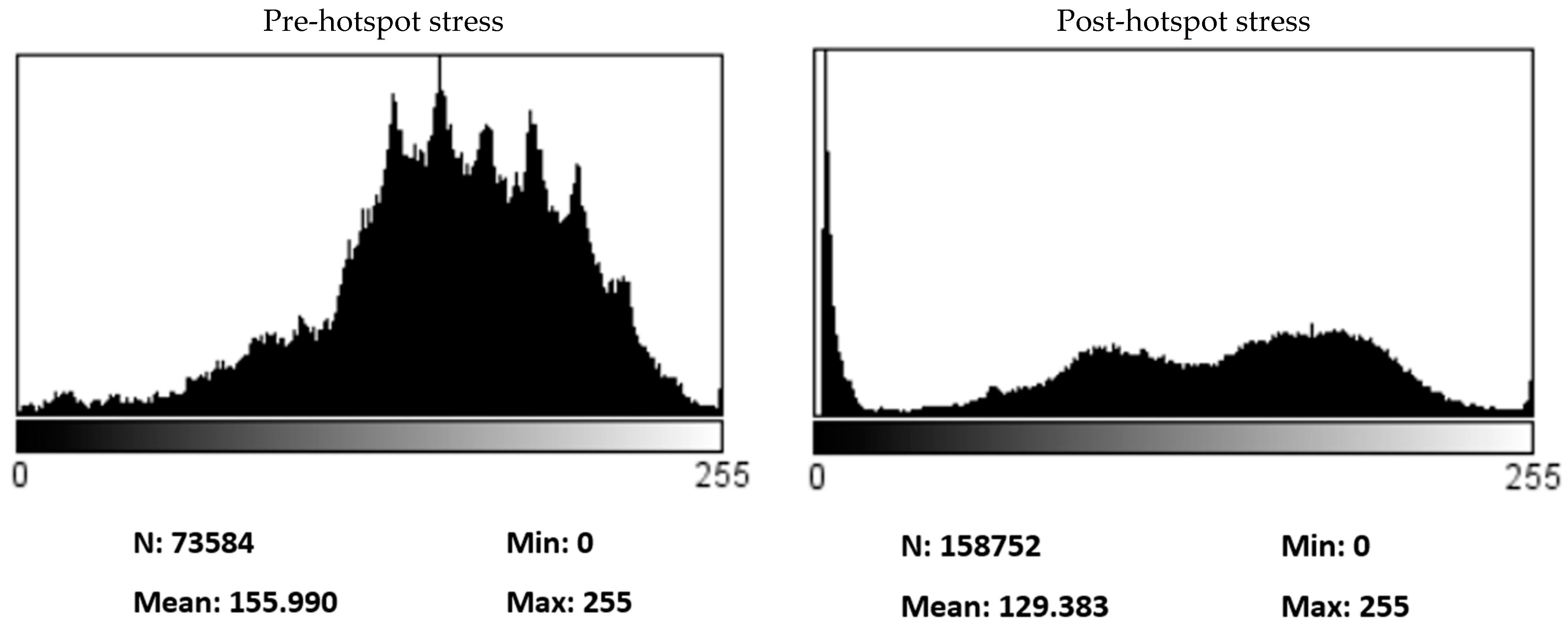
In order to evaluate the change in the EL image pixel intensity pre- and post-hotspot experiment, a grayscale analysis was conducted on the GG modules EL images, as shown in Figure 10. Grayscale analysis is a method used to evaluate the homogeneity of solar cells within a PV module and is a non-destructive and non-invasive technique. The prestressed GG module experienced a reduction of nearly 10.3% in the mean grayscale value post-hotspot experiment, where the lowermost substring experienced a significant decrease of nearly 17% in the grayscale value shown in Figure 10 (right). This supports the considerable cell-level defects evident in the lowermost substring of the prestressed GG module, as shown in the EL image in Figure 7 (right). For the top and the middle substrings, the grayscale value dropped by about 7.4%. Similarly, for the pristine GG module, the mean grayscale value decreased by only 3.7%, suggesting that there was no noticeable decrease in the grayscale value or the pixel intensity of this module post-hotspot experiment.

3.3. Degradation in Electrical Parameters Post-Hotspot Test

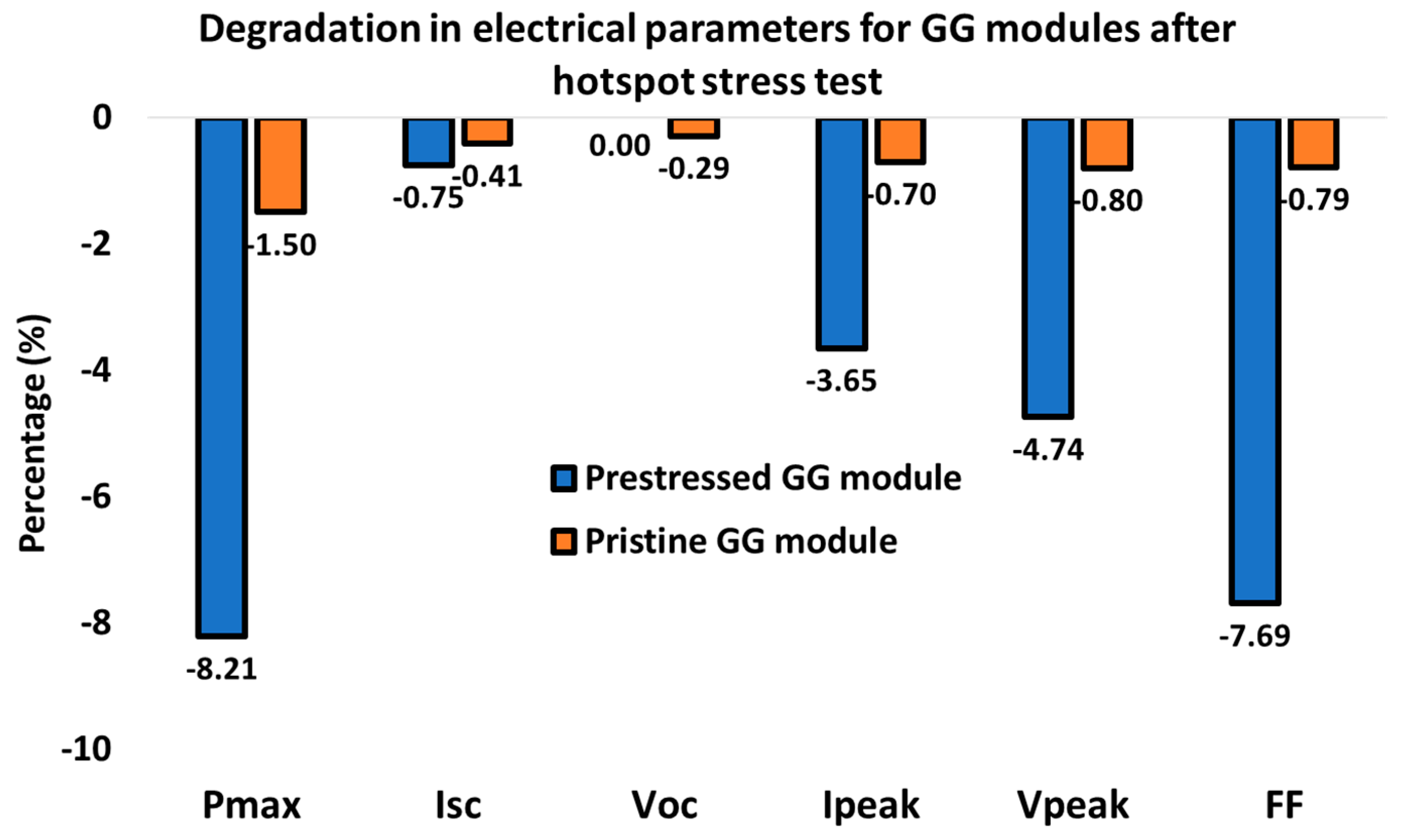
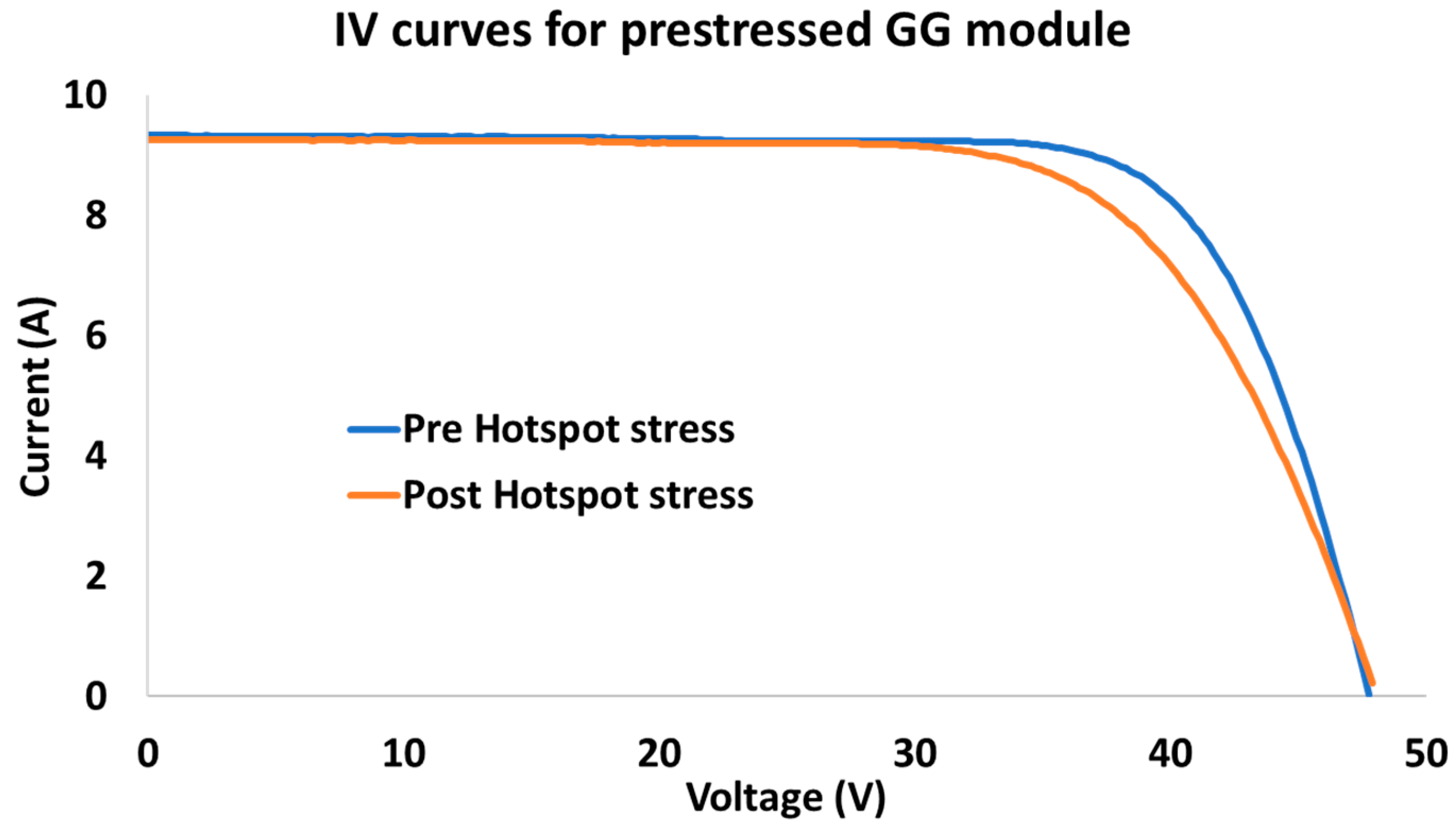
The impact of the hotspot stress on the GG modules was analyzed using the decline observed in the electrical parameters displayed in the bar plot in Figure 11, which was quantified by measuring the I-V curves. After undergoing 600 thermal cycles, the Pmax of the prestressed GG module was calculated to be 336 W. However, following the hotspot experiment, this Pmax value significantly dropped by nearly 8.2% to 308 W, causing 28 W of power loss. A trivial decline of less than a percent was observed in the value of Voc, and Isc, while the FF decreased by 7.7%, as displayed in Figure 11. Furthermore, the Ipeak and Vpeak degraded by about 3.6% and 4.7%, respectively, shown in Figure 11. This degradation was validated by the I-V curves shown in Figure 12, where the knee of the post-hotspot I-V curve clearly demonstrates an early bend, indicating degradation in the electrical performance parameters of Vpeak and Ipeak. Moreover, the value of Rs raised by roughly 0.91%, increasing from 0.6814 ohms to 0.6876 ohms. In contrast, the value of Rsh dropped considerably by 10.4%, falling from 7729 ohms to 6925 ohms. A smaller value for the shunt resistance implies that there is an additional pathway available for the electrical current to flow through, resulting in a reduction of solar cells’ efficiency [45] and adversely affecting the modules’ performance [35].
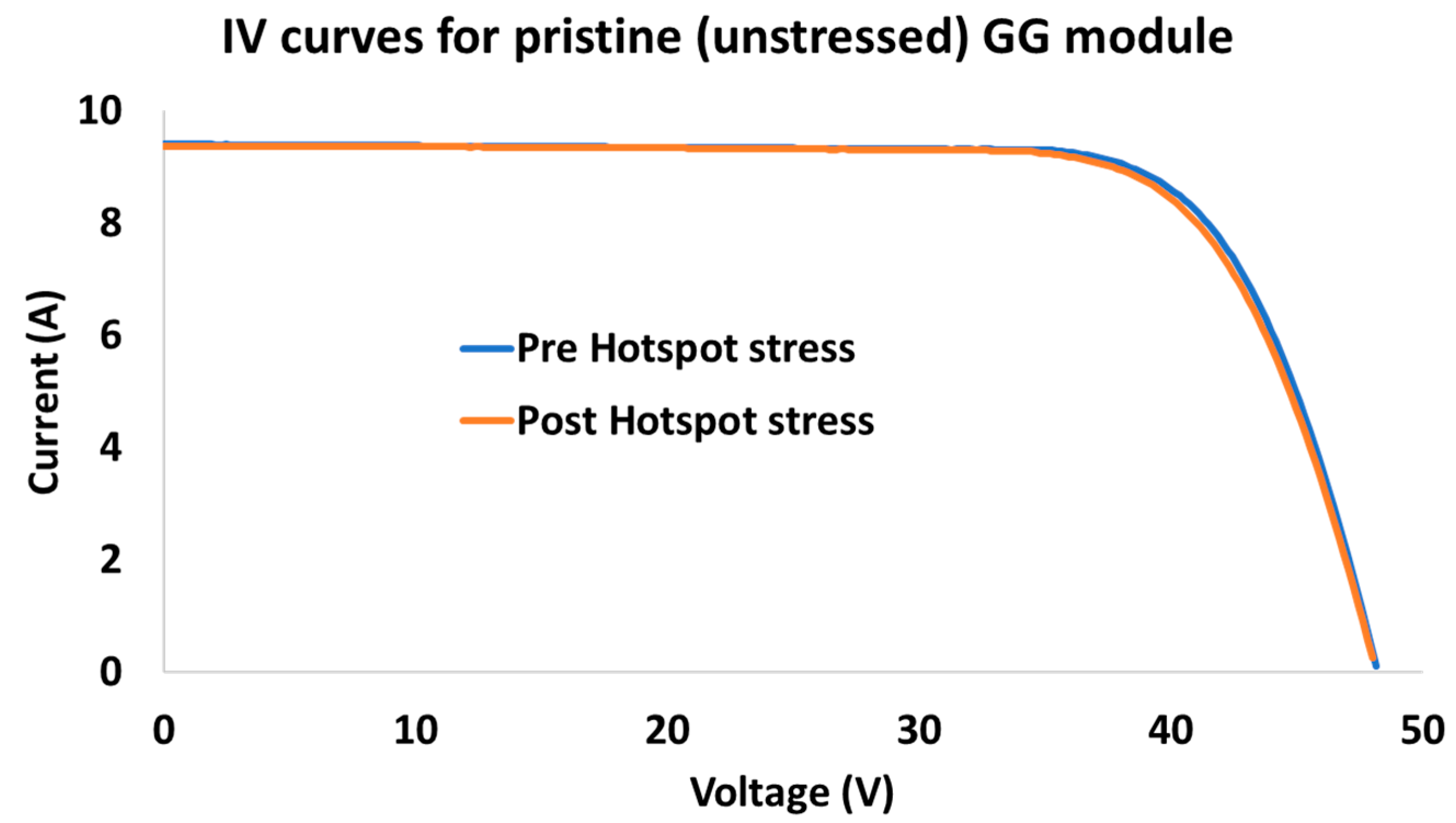
Similarly, the Pmax of the pristine GG module was initially calculated to be 346 W. However, following the hotspot experiment, this Pmax value dropped trivially by only 1.5% to 341 W, causing only a 5 W of power loss. A minor decline of less than half a percent was observed in the value of Voc and Isc, while the Ipeak, Vpeak, and FF decreased by almost 0.8%, as displayed in Figure 11. Post-hotspot analysis indicated no considerable change in the value of Rsh or Rs, along with no significant change in the knee of the I-V curve shown in Figure 13. This implies that the pristine GG module successfully endured the hotspot stress with only minimal deterioration in its electrical parameters.

3.4. Potential Reasons for Degradation in GG Modules

The EL image shown in Figure 7 (right) reveals cell-level defects that may have potentially caused the decline in the maximum power of the prestressed GG module. The observed defects were identified as multiple cell cracks on several silicon-wafers that appeared as dark line-shaped unsymmetrical patterns. During thermal cycling, the differential thermal expansion and contraction of the various materials within the module can also cause thermal stresses on the silicon wafer, leading to cracking. The silicon wafer is usually coated with thin layers of materials, including metal contacts, antireflection coatings, and encapsulant materials. The coefficients of thermal expansion of these materials are different, which causes differential thermal expansion and contraction [46] during thermal cycling. If the thermal stress exceeds the strength of the silicon wafer, it can initiate cracks. Furthermore, the cracks could also have been the result of an extreme level of thermal stress at the solder joints [47] as a result of localized heating during the hotspot experiment. The majority of the cracks identified in the EL image appeared at specific locations and were found to have originated particularly near the junction connecting the busbar and the fingers, indicating that they might have developed due to solder fatigue [48]. The analysis of the EL image indicates that the junction connecting the busbar and the fingers are particularly susceptible to thermal stress [48]. Cell cracks can obstruct the flow of electrical current, leading to power loss and causing a lasting mismatch in the cells of photovoltaic modules. This mismatch can create uneven thermal stress in the PV modules [49]. The extent of this mismatch is the primary reason for the hotspot severity level and variation in EL and IV data.
The prestressed GG module EL image also revealed considerable breakages of fingers in the silicon-wafers in addition to cell cracks. These damaged fingers appeared as dark rectangular-shaped areas that developed and emerged near the junction connecting the busbar and fingers beneath the copper-ribbon, which is a point where the busbars and fingers are attached together. The areas of finger breakages in the prestressed GG module were non-uniform, with varying extents of breakages in several locations of this module, as illustrated in Figure 7 (right). This module exhibited the highest concentration of visible finger breakages along its top and bottom edges. Finger breakage is a failure mechanism that can occur in the silicon wafers of solar cells due to the differential thermal expansion between the metal fingers and the silicon wafer. During operation, the metal fingers that interconnect the cells and the silicon wafer expand and contract at different rates due to the differences in their coefficients of thermal expansion [46]. This differential thermal expansion can cause localized stress concentrations at the corners of the metal fingers, leading to the initiation of micro-cracks in the silicon wafer. These micro-cracks can propagate over time due to continued thermal cycling, leading to finger breakage and reduced power output or even a complete module failure.
The EL image shown in Figure 7 (right) for a prestressed GG module after the hotspot experiment also indicates the presence of several severely affected solar cells, possibly due to finger breaks and shunt faults caused by damaged cell interconnections [16]. These cells were stressed during the hotspot experiment and were partially shaded under the condition of worst-case shading, resulting in high thermal stress. The EL image in Figure 7 (right) illustrates these cells as completely dark areas, indicating an absence or limitation of electrical current through them. As a result, there is little or no contribution of power generation from these cells, and they cause a decrease in the modules’ grayscale value in the EL images. Furthermore, the prestressed GG module EL image presented in Figure 7 (right) demonstrates failures of solder-bonds. This is evident from the uniformly decreased EL intensity on either side of several busbars as a result of the reduced injection of electrical current [42]. The solder layer in PV modules plays a crucial role in ensuring a reliable mechanical and electrical bond between the metallization and interconnects. However, the two primary factors that contribute to the deterioration of solder bonds are thermal aging and thermomechanical fatigue [42].
In addition, Figure 7 (right) illustrates cell interconnect ribbon failure, which stems from thermally-induced strain [46] resulting from metal fatigue. Since the electrical current is only carried through one of these ribbons, one side of the cell is heated more intensely than the other, leading to a higher brightness, as evident in the EL image represented in Figure 7 (right). A potential reason for the fatigue observed in the ribbons interconnecting the solar cells is the difference in the CTE of the solder-joints, which attaches the copper-ribbons with silicon-wafers [46]. The cyclic mechanical stress on the cell interconnection ribbons can potentially result in localized stress concentrations on the ribbon surface, leading to the formation of micro-cracks. The combination of cyclic mechanical stress and corrosion can lead to fatigue failure of the interconnect ribbons, causing an open circuit in the module and reduced power output.
Copper ribbons are soldered to interconnect solar cells in PV modules. However, the glass cover on either side of the GG modules can result in a variation of glass temperature, causing stress which can lead to cell displacement in the encapsulation layer. As a result, the copper-ribbon experiences an increased strain because glass has a larger CTE compared to c-Si solar cells. With an increase in temperature, the silicon solar cells tend to move away from each other, developing a gap between them, which expands proportionally as the temperature rises [50]. During the cooling phase, the gap contracts due to a drop in temperature. Although the copper-ribbon having a larger CTE compared to glass, the copper-ribbon segment located between two solar cells is subject to strain due to the displacement of cells caused by the temperature changes [46]. This stress can cause damage to the interconnects in those regions, hindering the effective collection of electrical current. The negative effects of damaged interconnected ribbons on modules’ performance or hotspots in the field may occur after several years to become apparent, and multiple module design factors may also contribute to the interconnection breakage.

4. Conclusions

This study examined the effect of hotspot stress on a pristine GG module and a prestressed GG module subjected to accelerated thermal cycling, imitating real-world conditions. Infrared images during the experiment showed that shaded cells in both the modules reached a high hotspot temperature of nearly 197 °C. Post-hotspot testing, electroluminescence images showed multiple defects, like cracks, broken fingers, and cell failure, in the prestressed GG module, leading to a notable 8.2% Pmax degradation. Conversely, the pristine GG module, showing no significant damage, degraded only by about 1.5%.
This marked Pmax drop in the prestressed GG module could be due to the defects arising from thermal cycling. The EL intensity also dropped significantly in the prestressed GG module compared to a slight degradation in the pristine one. This suggested that the prestressed GG module, having undergone accelerated thermal cycling, was more severely impacted by the hotspot test. Hence, the prestressed GG module is more susceptible to hotspots which can compromise its reliability and safety as this module represents a simulated field-aged module and experiences significant CTE mismatch between several components, unlike the pristine GG module. It is important to acknowledge that the test results and conclusions of this study may not be fully generalized for all types of GG modules in the market because this study does not involve a statistically significant number of modules. Hence, it is possible that factors other than the superstrate and substrate materials, such as the manufacturer’s quality control or distinct bill of materials, may influence the test results.

5. Recommendation for Future Work

Based on the test results obtained in this investigation, the hotspot testing is recommended to be conducted on a thermal cycled prestressed module rather than a pristine module, as is done in the current IEC 61215 standard. In doing so, we can more accurately represent a field-stressed module experiencing hotspot stress under real-world conditions. Furthermore, for future research in hotspot testing of both prestressed (with thermal cycling) and pristine modules, it is recommended to expand the sample size and diversify the module types to include a broader range of technologies to ensure a more comprehensive understanding of hotspots in photovoltaic modules. Lastly, long-term field studies monitoring the performance of both prestressed and pristine GG modules could provide valuable insights into how these modules degrade over time in real-world conditions.

Author Contributions

Conceptualization, M.A., A.K., F.i.M. and G.T.; Methodology, M.A., A.K., F.i.M. and G.T.; Validation, M.A. and F.i.M.; Formal analysis, M.A.; Investigation, M.A., A.K. and F.i.M.; Resources, A.K. and G.T.; Writing—original draft, M.A.; Writing—review & editing, M.A., A.K., F.i.M. and G.T.; Supervision, A.K. and G.T.; Project administration, G.T.; Funding acquisition, G.T. All authors have read and agreed to the published version of the manuscript.

Funding

This material is based upon work supported by the Department of Energy, Office of Energy Efficiency and Renewable Energy (EERE), under Award Number DE-EE-0008565.

Institutional Review Board Statement

Not applicable.

Informed Consent Statement

Not applicable.

Data Availability Statement

Not applicable.

Conflicts of Interest

The authors declare no conflict of interest.

References

  1. International Technology Roadmap for Photovoltaic (ITRPV). 2022. Available online: https://etip-pv.eu/news/other-news/international-technology-roadmap-for-photovoltaic-itrpv-r-d-findings-from-the-13th-edition/ (accessed on 9 March 2023).
  2. Sinha, A.; Sulas-Kern, D.B.; Owen-Bellini, M.; Spinella, L.; Uličná, S.; Pelaez, S.A.; Johnston, S.; Schelhas, L.T. Glass/glass photovoltaic module reliability and degradation: A review. J. Phys. D Appl. Phys. 2021, 54, 413002. [Google Scholar] [CrossRef]
  3. Mahmood, F.I.; Kumar, A.; Afridi, M.; TamizhMani, G. Potential induced degradation in c-Si glass-glass modules after extended damp heat stress. Sol. Energy 2023, 254, 102–111. [Google Scholar] [CrossRef]
  4. Tang, J.; Ju, C.; Lv, R.; Zeng, X.; Chen, J.; Fu, D.; Jaubert, J.-N.; Xu, T. The Performance of Double Glass Photovoltaic Modules under Composite Test Conditions. Energy Procedia 2017, 130, 87–93. [Google Scholar] [CrossRef]
  5. Cattaneo, G.; Faes, A.; Li, H.Y.; Galliano, F.; Gragert, M.; Yao, Y.; Grischke, R.; Söderström, T.; Despeisse, M.; Ballif, C.; et al. Lamination process and encapsulation materials for glass--glass PV module design. Photovolt. Int. 2015, 27, 1–8. [Google Scholar]
  6. Zhang, Y.; Xu, J.; Mao, J.; Tao, J.; Shen, H.; Chen, Y.; Feng, Z.; Verlinden, P.J.; Yang, P.; Chu, J. Long-term reliability of silicon wafer-based traditional backsheet modules and double glass modules. RSC Adv. 2015, 5, 65768–65774. [Google Scholar] [CrossRef]
  7. Soderstrom, T.; Yao, Y.; Grischke, R.; Gragert, M.; Demaurex, B.; Strahm, B.; Papet, P.; Mehlich, H.; Koenig, M.; Waltinger, A.; et al. Low Cost High Energy Yield Solar Module Lines and Its Applications. In Proceedings of the IEEE 42nd Photovoltaic Specialist Conference (PVSC), New Orleans, LA, USA, 14–19 June 2015; pp. 1–6. [Google Scholar]
  8. Cote, B.M.; Slauch, I.M.; Silverman, T.J.; Deceglie, M.G.; Ferry, V.E. Insulation or Irradiance: Exploring Why Bifacial Photovoltaics Run Hot. In Proceedings of the IEEE Photovoltaic Specialists Conference (PVSC), Fort Lauderdale, FL, USA, 20–25 June 2021; pp. 1228–1232. [Google Scholar]
  9. Tina, G.M.; Scavo, F.B.; Aneli, S.; Gagliano, A. Assessment of the electrical and thermal performances of building integrated bifacial photovoltaic modules. J. Clean Prod. 2021, 313, 127906. [Google Scholar] [CrossRef]
  10. Sinapis, K.; van den Donker, M. Bipv Report 2013. 2012. Available online: https://repository.tno.nl//islandora/object/uuid:98b2fff8-b911-4247-a40b-359e944991b4 (accessed on 9 March 2023).
  11. Du, Y.; Tao, W.; Liu, Y.; Jiang, J.; Huang, H. Heat transfer modeling and temperature experiments of crystalline silicon photovoltaic modules. Sol. Energy 2017, 146, 257–263. [Google Scholar] [CrossRef]
  12. Muller, A.; Friedrich, L.; Reichel, C.; Herceg, S.; Mittag, M.; Neuhaus, D.H. A comparative life cycle assessment of silicon PV modules: Impact of module design, manufacturing location and inventory. Sol. Energy Mater. Sol. Cells 2021, 230, 111277. [Google Scholar] [CrossRef]
  13. Hanifi, H.; Pander, M.; Zeller, U.; Ilse, K.; Dassler, D.; Mirza, M.; Bahattab, M.A.; Jaeckel, B.; Hagendorf, C.; Ebert, M.; et al. Loss analysis and optimization of PV module components and design to achieve higher energy yield and longer service life in desert regions. Appl. Energy 2020, 280, 116028. [Google Scholar] [CrossRef]
  14. Guiheneuf, V.; Delaleux, F.; Riou, O.; Logerais, P.-O.; Durastanti, J.-F. Investigation of damp heat effects on glass properties for photovoltaic applications. Corros. Eng. Sci. Technol. 2016, 52, 170–177. [Google Scholar] [CrossRef]
  15. Wohlgemuth, J.H.; Cunningham, D.W.; Monus, P.; Miller, J.; Nguyen, A. Long Term Reliability of Photovoltaic Modules. In Proceedings of the IEEE 4th World Conference on Photovoltaic Energy Conference, Waikoloa, HI, USA, 7–12 May 2006; pp. 2050–2053. [Google Scholar]
  16. Köntges, M.; Kurtz, S.; Packard, C.E.; Jahn, U.; Berger, K.A.; Kato, K.; Friesen, T.; Liu, H.; Van Iseghem, M.; Wohlgemuth, J.; et al. Review of Failures of Photovoltaic Modules; International Energy Agency: Paris, France, 2014. [Google Scholar]
  17. Ferrara, C.; Ferrara, P.D. Why Do PV Modules Fail. Energy Procedia 2012, 15, 379–387. [Google Scholar] [CrossRef]
  18. Lee, J.E.; Bae, S.; Oh, W.; Park, H.; Kim, S.M.; Lee, D.; Nam, J.; Mo, C.B.; Kim, D.; Yang, J.; et al. Investigation of damage caused by partial shading of CuInxGa (1-x) Se2 photovoltaic modules with bypass diodes. Prog. Photovolt. Res. Appl. 2016, 24, 1035–1043. [Google Scholar] [CrossRef]
  19. Akram, M.W.; Li, G.; Jin, Y.; Zhu, C.; Javaid, A.; Khan, M.U. Study of manufacturing and hotspot formation in cut cell and full cell PV modules. Sol. Energy 2020, 203, 247–259. [Google Scholar] [CrossRef]
  20. Afridi, M.A.; Arbab, M.; Bilal, M.; Ullah, H.; Ullah, N. Determining the effect of soiling and dirt particles at various tilt angles of photovoltaic modules. Int. J. Eng. Work. 2017, 4, 143–146. [Google Scholar]
  21. Cox, C., III; Silversmith, D.; Mountain, R. Reduction of Photovoltaic Cell Reverse Breakdown by a Peripheral Bypass Diode; Massachusetts Institute of Technology: Lexington, MA, USA, 1982. [Google Scholar]
  22. Jordan, D.C.; Silverman, T.J.; Wohlgemuth, J.H.; Kurtz, S.R.; VanSant, K.T. Photovoltaic failure and degradation modes. Prog. Photovolt. Res. Appl. 2017, 25, 318–326. [Google Scholar] [CrossRef]
  23. Xu, T.; Deng, S.; Zhang, G.; Zhang, Z. Research on hot spot risk of high wattage solar modules. Sol. Energy 2021, 230, 583–590. [Google Scholar] [CrossRef]
  24. Wang, A.; Xuan, Y. Close examination of localized hot spots within photovoltaic modules. Energy Convers. Manag. 2021, 234, 113959. [Google Scholar] [CrossRef]
  25. Olalla, C.; Hasan, N.; Deline, C.; Maksimović, D. Mitigation of Hot-Spots in Photovoltaic Systems Using Distributed Power Electronics. Energies 2018, 11, 726. [Google Scholar] [CrossRef] [Green Version]
  26. Afridi, M.; Tatapudi, S.; Flicker, J.; Srinivasan, D.; Tamizhmani, G. Reliability evaluation of DC power optimizers for photovoltaic systems: Accelerated testing at high temperatures with fixed and cyclic power stresses. Eng. Fail. Anal. 2023, 152, 107484. [Google Scholar] [CrossRef]
  27. Khodapanah, M.; Ghanbari, T.; Moshksar, E.; Hosseini, Z. Partial shading detection and hotspot prediction in photovoltaic systems based on numerical differentiation and integration of the PV curves. IET Renew. Power Gener. 2022, 17, 279–295. [Google Scholar] [CrossRef]
  28. Chen, H.; Yi, H.; Jiang, B.; Zhang, K.; Chen, Z. Data-Driven Detection of Hot Spots in Photovoltaic Energy Systems. IEEE Trans. Syst. Man. Cybern. Syst. 2019, 49, 1731–1738. [Google Scholar] [CrossRef]
  29. Muñoz, J.; Lorenzo, E.; Martínez-Moreno, F.; Marroyo, L.; García, M. An investigation into hot-spots in two large grid-connected PV plants. Prog. Photovoltaics Res. Appl. 2008, 16, 693–701. [Google Scholar] [CrossRef] [Green Version]
  30. Hanifi, H.; Pander, M.; Jaeckel, B.; Schneider, J.; Bakhtiari, A.; Maier, W. A novel electrical approach to protect PV modules under various partial shading situations. Sol. Energy 2019, 193, 814–819. [Google Scholar] [CrossRef]
  31. Dhimish, M.; Badran, G. Current limiter circuit to avoid photovoltaic mismatch conditions including hot-spots and shading. Renew. Energy 2019, 145, 2201–2216. [Google Scholar] [CrossRef]
  32. Guerriero, P.; Tricoli, P.; Daliento, S. A bypass circuit for avoiding the hot spot in PV modules. Sol. Energy 2019, 181, 430–438. [Google Scholar] [CrossRef]
  33. Oh, W.; Choi, H.; Seo, K.W.; Kim, D.; Kim, S.-Y.; Lee, H.-S.; Hwang, H.; Kim, D. Evaluation based on performance and failure of PV system in 10 years field-aged 1 MW PV power plant. Microelectron. Reliab. 2020, 114, 113763. [Google Scholar] [CrossRef]
  34. Kaplani, E. Degradation Effects in sc-Si PV Modules Subjected to Natural and Induced Ageing after Several Years of Field Operation. J. Eng. Sci. Technol. Rev. 2012, 5, 18–23. [Google Scholar] [CrossRef]
  35. Meyer, E.; van Dyk, E.E. The Effect of Reduced Shunt Resistance and Shading on Photovoltaic Module Performance. In Proceedings of the Conference Record of the IEEE Photovoltaic Specialists Conference, Lake Buena Vista, FL, USA, 3–7 January 2005; pp. 1331–1334. [Google Scholar] [CrossRef]
  36. Afridi, M.; Kumar, A.; Mahmood, F.I.; Tamizhmani, G. Hotspot testing of glass/backsheet and glass/glass PV modules pre-stressed in extended thermal cycling. Sol. Energy 2023, 249, 467–475. [Google Scholar] [CrossRef]
  37. Ali, M.U.; Khan, H.F.; Masud, M.; Kallu, K.D.; Zafar, A. A machine learning framework to identify the hotspot in photovoltaic module using infrared thermography. Solar Energy 2020, 208, 643–651. [Google Scholar] [CrossRef]
  38. Niazi, K.A.K.; Akhtar, W.; Khan, H.A.; Yang, Y.; Athar, S. Hotspot diagnosis for solar photovoltaic modules using a Naive Bayes classifier. Sol. Energy 2019, 190, 34–43. [Google Scholar] [CrossRef]
  39. IEC 61215-2:2016; Terrestrial Photovoltaic (PV) Modules–Design Qualification and Type Approval—Part 2: Test Procedures. IEC: Geneva, Switzerland, 2016.
  40. Zaidi, B. Solar Panels and Photovoltaic Materials; InTechOpen: London, UK, 2018. [Google Scholar]
  41. Roy, S.; Kumar, S.; Gupta, R. Investigation and analysis of finger breakages in commercial crystalline silicon photovoltaic modules under standard thermal cycling test. Eng. Fail. Anal. 2019, 101, 309–319. [Google Scholar] [CrossRef]
  42. Kumar, S.; Meena, R.; Gupta, R. Finger and interconnect degradations in crystalline silicon photovoltaic modules: A review. Sol. Energy Mater. Sol. Cells 2021, 230, 111296. [Google Scholar] [CrossRef]
  43. Sporleder, K.; Naumann, V.; Bauer, J.; Richter, S.; Hähnel, A.; Großer, S.; Turek, M.; Hagendorf, C. Root cause analysis on corrosive potential-induced degradation effects at the rear side of bifacial silicon PERC solar cells. Sol. Energy Mater. Sol. Cells 2019, 201, 110062. [Google Scholar] [CrossRef]
  44. Krauss, K.; Fertig, F.; Menzel, D.; Rein, S. Light-induced Degradation of Silicon Solar Cells with Aluminiumoxide Passivated Rear Side. Energy Procedia 2015, 77, 599–606. [Google Scholar] [CrossRef]
  45. Bilal, M.; Arbab, M.N.; Afridi, M.Z.U.A.; Khattak, A. Increasing the output power and efficiency of solar panel by using concentrator photovoltaics (CPV). Int. J. Eng. Work. 2016, 3, 98–102. [Google Scholar]
  46. Hu, Y.; French, R.H. Degradation and Failure Mechanisms of PV Module Interconnects. In Durability and Reliability of Polymers and Other Materials in Photovoltaic Modules; Elsevier: Amsterdam, The Netherlands, 2019; pp. 119–134. [Google Scholar] [CrossRef]
  47. Dhimish, M.; Hu, Y. Rapid testing on the effect of cracks on solar cells output power performance and thermal operation. Sci. Rep. 2022, 12, 12168. [Google Scholar] [CrossRef]
  48. Niyaz, H.M.; Meena, R.; Gupta, R. Impact of cracks on crystalline silicon photovoltaic modules temperature distribution. Sol. Energy 2021, 225, 148–161. [Google Scholar] [CrossRef]
  49. Tsanakas, J.A.; Ha, L.; Buerhop, C. Faults and infrared thermographic diagnosis in operating c-Si photovoltaic modules: A review of research and future challenges. Renew. Sustain. Energy Rev. 2016, 62, 695–709. [Google Scholar] [CrossRef]
  50. Meier, R.; Kraemer, F.; Wiese, S.; Wolter, K.-J.; Bagdahn, J. Reliability of Copper-Ribbons in Photovoltaic Modules Under Thermo-Mechanical Loading. In Proceedings of the Conference Record of the IEEE Photovoltaic Specialists Conference, Honolulu, HI, USA, 20–25 June 2010; pp. 1283–1288. [Google Scholar] [CrossRef]
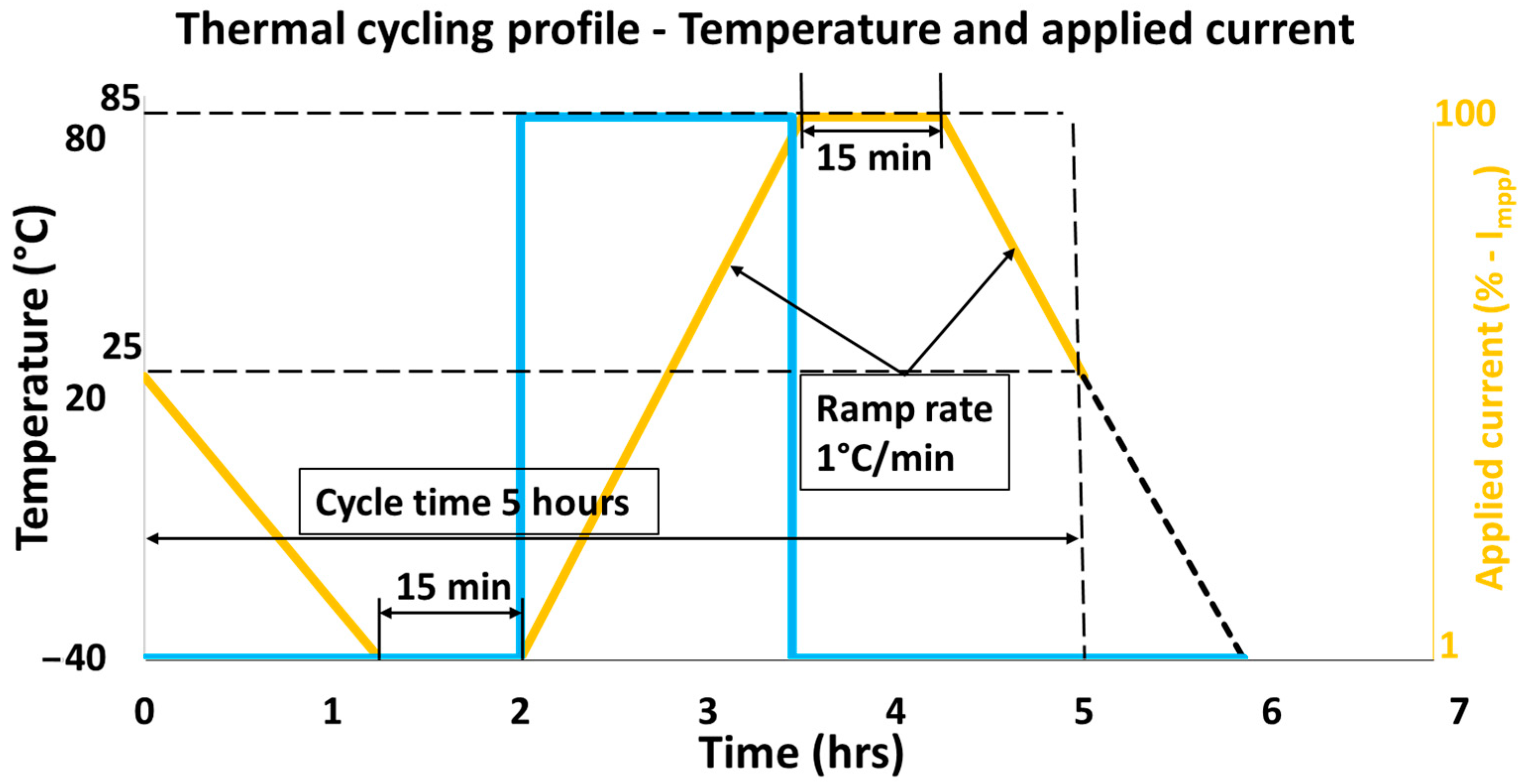
Figure 1. Profile used for thermal cycling according to IEC 61215 [34].
Sustainability 15 12131 g001
Figure 2. Illustration of a module under hotspot test outdoors on a two-axis tracker.
Sustainability 15 12131 g002
Figure 3. Experimental methodology for stressing and characterizing the GG modules.
Sustainability 15 12131 g003
Figure 4. IR images of the prestressed GG module illustrating individual test cells experiencing the hotspot stress.
Sustainability 15 12131 g004
Figure 5. IR images of the pristine GG module illustrating individual test cells experiencing the hotspot stress.
Sustainability 15 12131 g005
Figure 6. EL images of the front side for pristine GG module pre-hotspot (left) and post-hotspot (right) test where the red outline indicates the smallest shunt resistance cells, and the yellow outline indicates the large shunt resistance cell.
Sustainability 15 12131 g006
Figure 7. EL images of the front side for prestressed GG module pre-hotspot (left) and post-hotspot (right) test where the red outline indicates the smallest shunt resistance cells, and the yellow outline indicates the large shunt resistance cell.
Sustainability 15 12131 g007
Figure 8. EL images of the rear side for prestressed GG module pre-hotspot (left) and post-hotspot (right) test where the red outline indicates the smallest shunt resistance cells, and the yellow outline indicates the large shunt resistance cell.
Sustainability 15 12131 g008
Figure 9. EL images of the rear side for pristine GG module pre-hotspot (left) and post-hotspot (right) test where the red outline indicates the smallest shunt resistance cells, and the yellow outline indicates the large shunt resistance cell.
Sustainability 15 12131 g009
Figure 10. EL images grayscale histogram for the lowermost substring of the prestressed GG module pre-hotspot (left) and post-hotspot (right) test.
Sustainability 15 12131 g010
Figure 11. Degradation observed in electrical parameters for GG modules post-hotspot test.
Sustainability 15 12131 g011
Figure 12. I-V curves for prestressed GG module pre- and post-hotspot test.
Sustainability 15 12131 g012
Figure 13. I-V curves for pristine GG module pre- and post-hotspot test.
Sustainability 15 12131 g013
Disclaimer/Publisher’s Note: The statements, opinions and data contained in all publications are solely those of the individual author(s) and contributor(s) and not of MDPI and/or the editor(s). MDPI and/or the editor(s) disclaim responsibility for any injury to people or property resulting from any ideas, methods, instructions or products referred to in the content.