
Dynamic Behavior of Galloping Micro Energy Harvester with the Elliptical Bluff Body Using CFD Simulation

Abstract
:1. Introduction
2. Mathematical Modeling
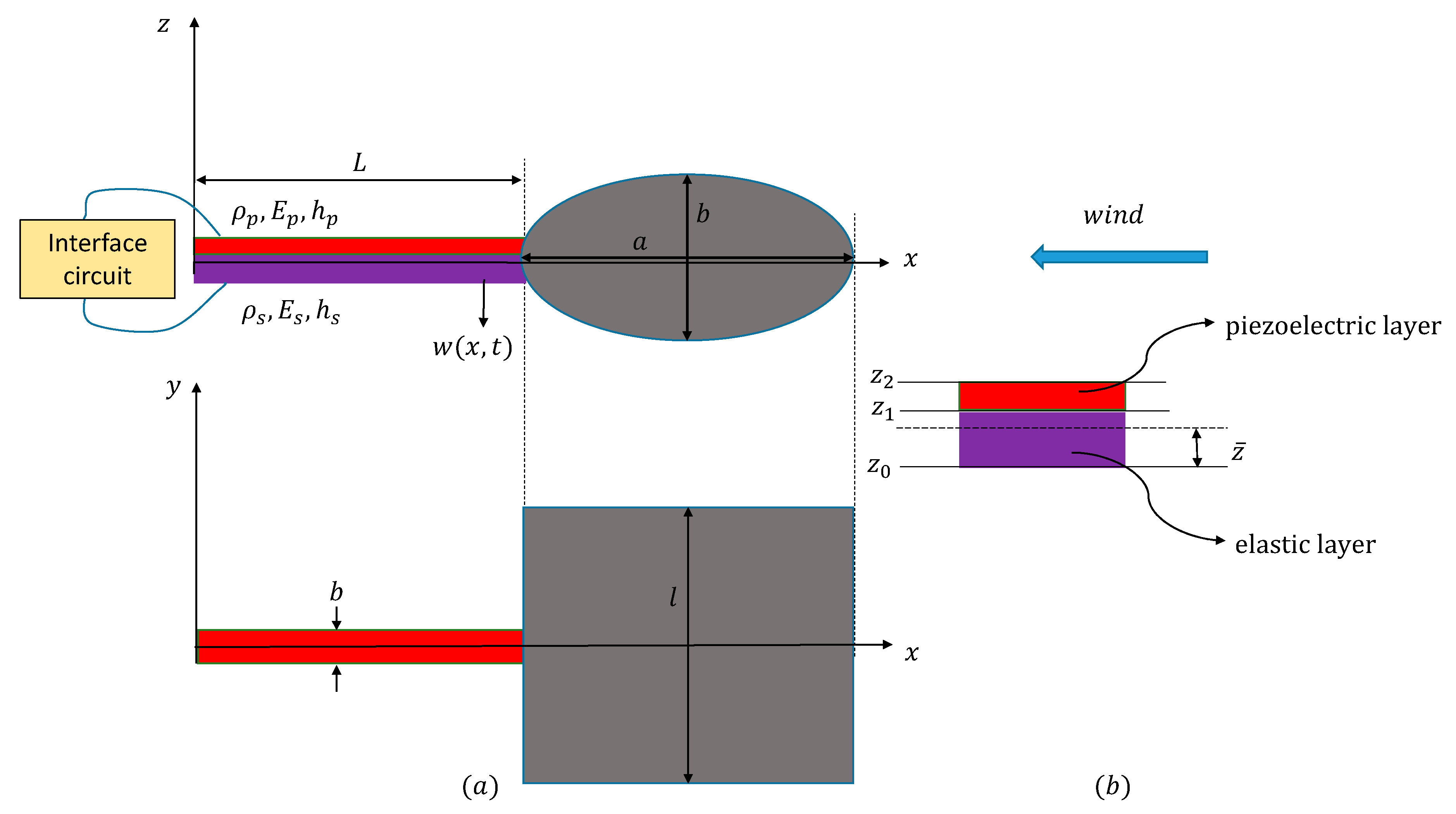
2.1. Coupled Electromechanical Governing Equations
2.2. Flow Field Simulation
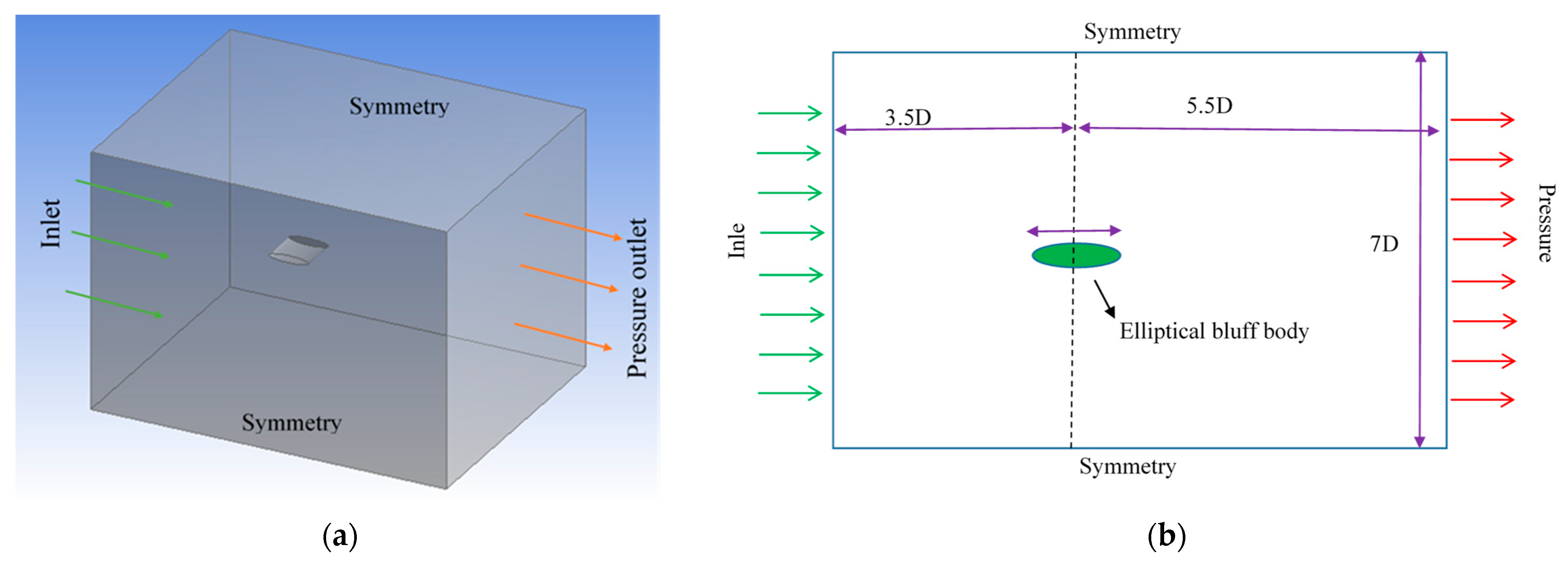
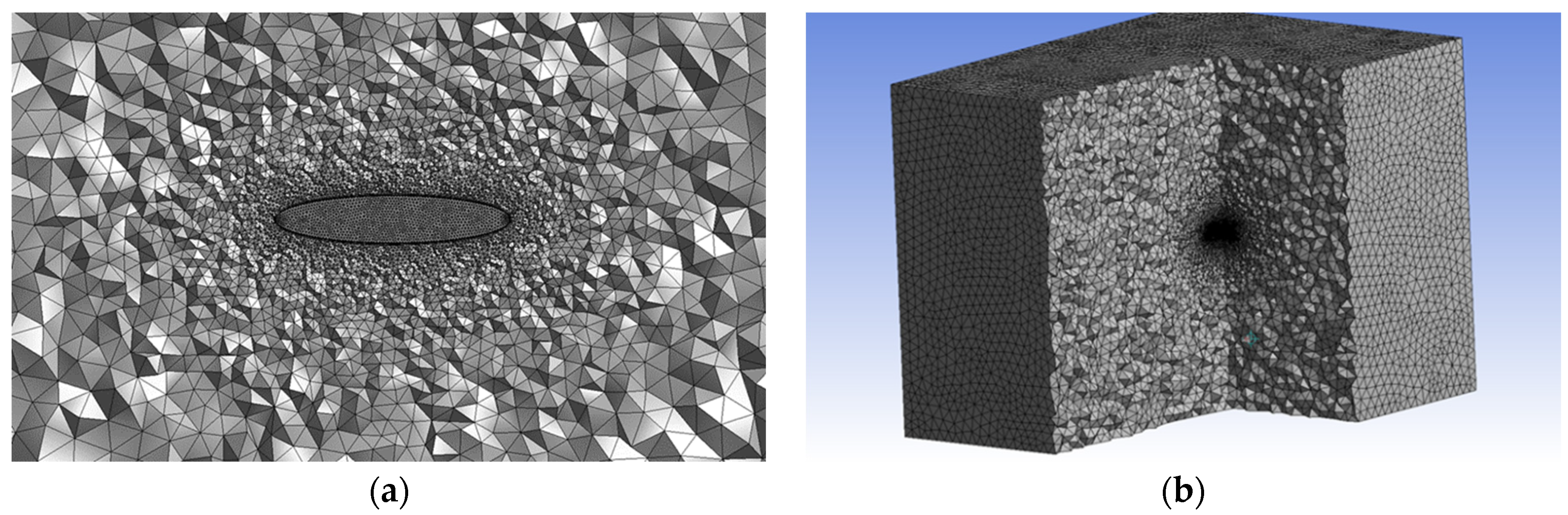
2.3. CFD Problem Definition and Numerical Considerations
3. Results
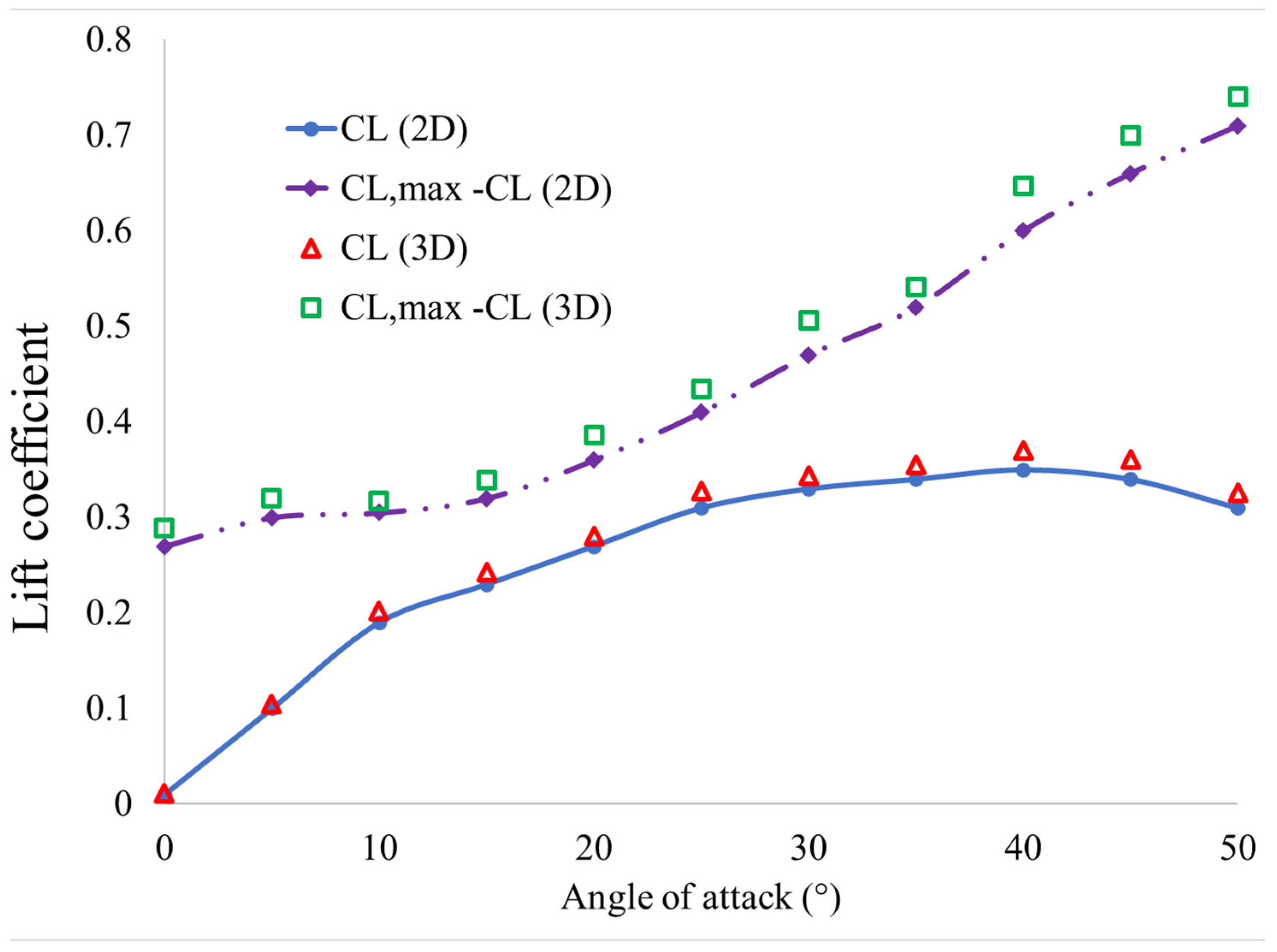
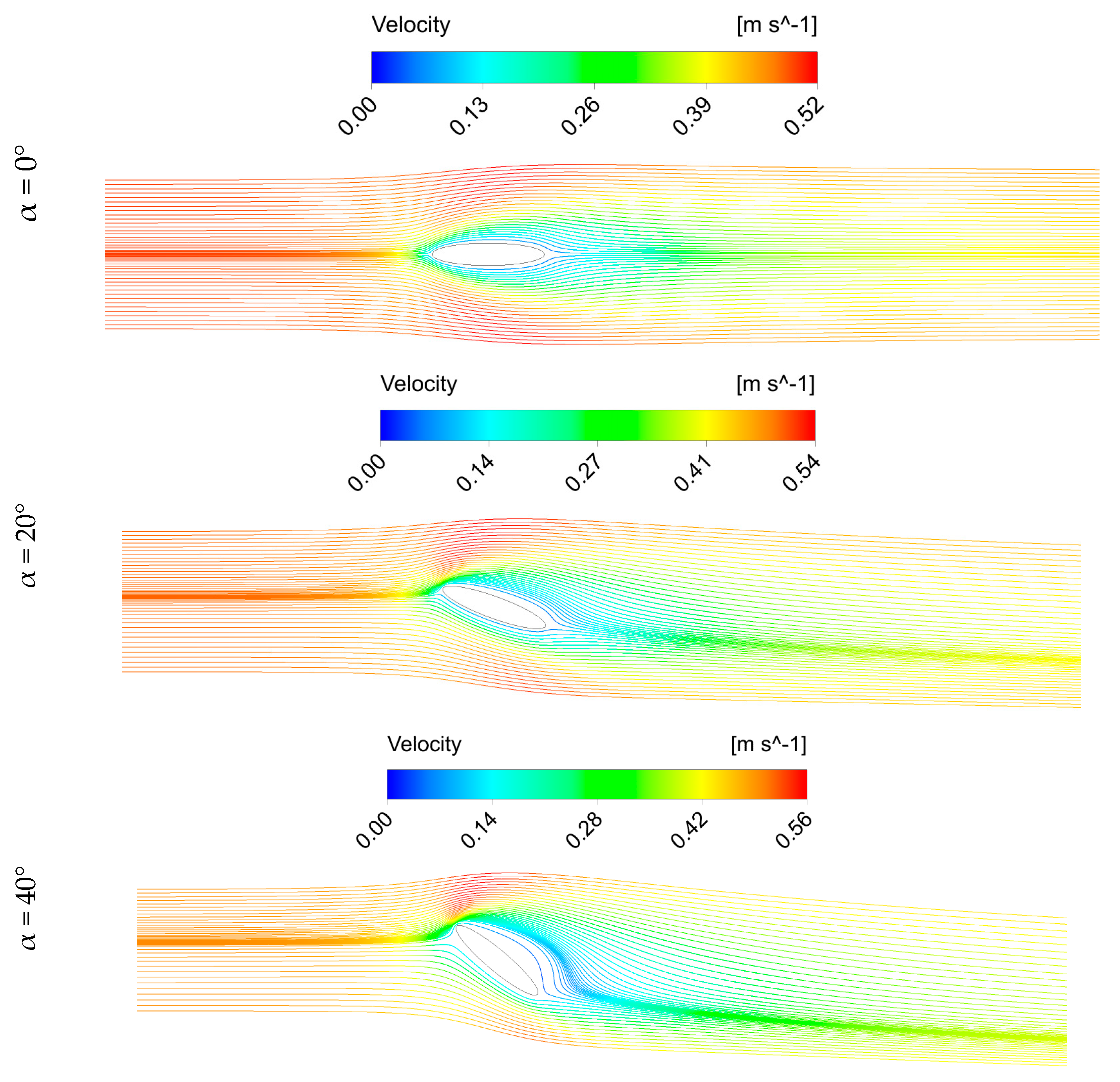
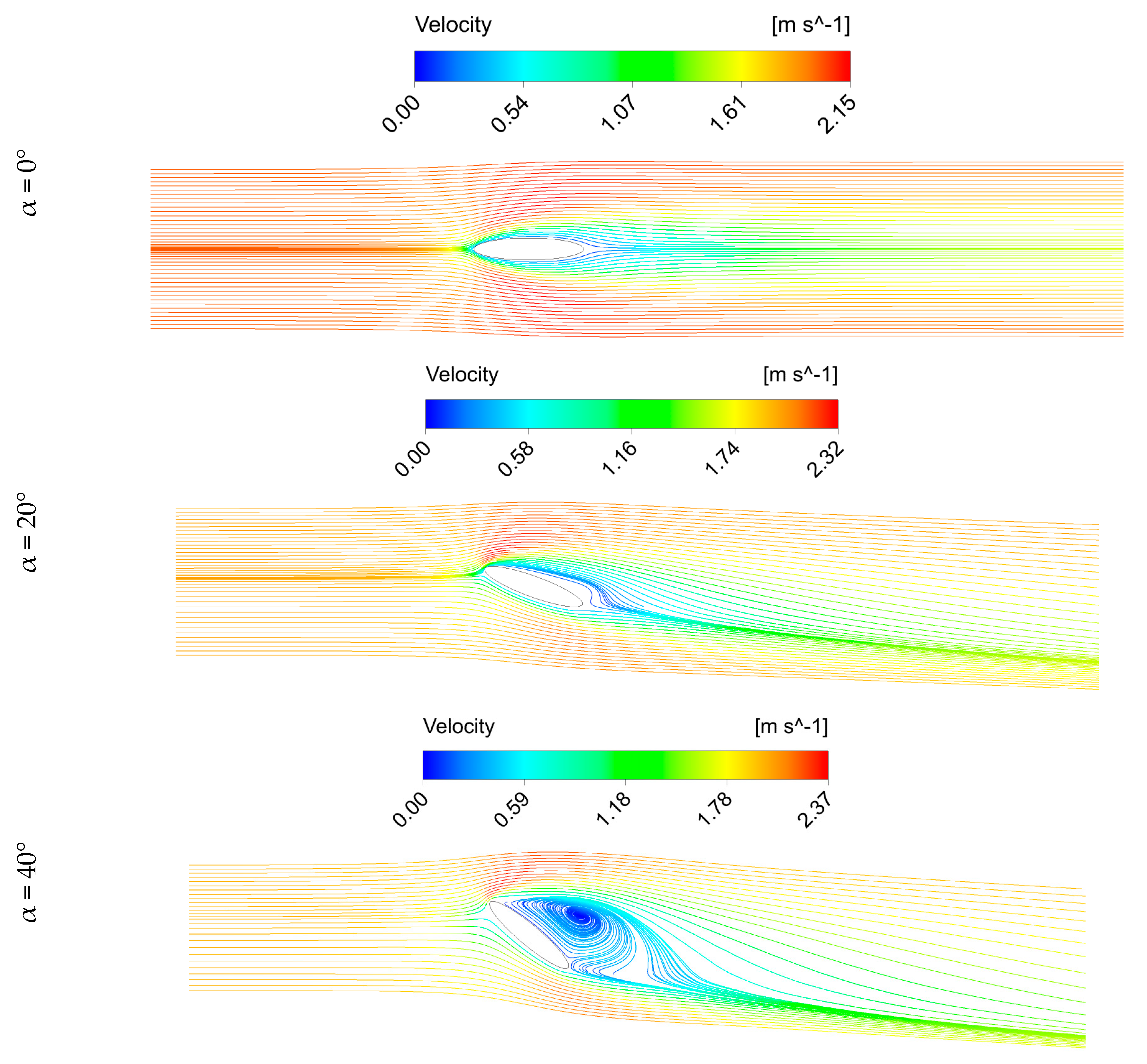
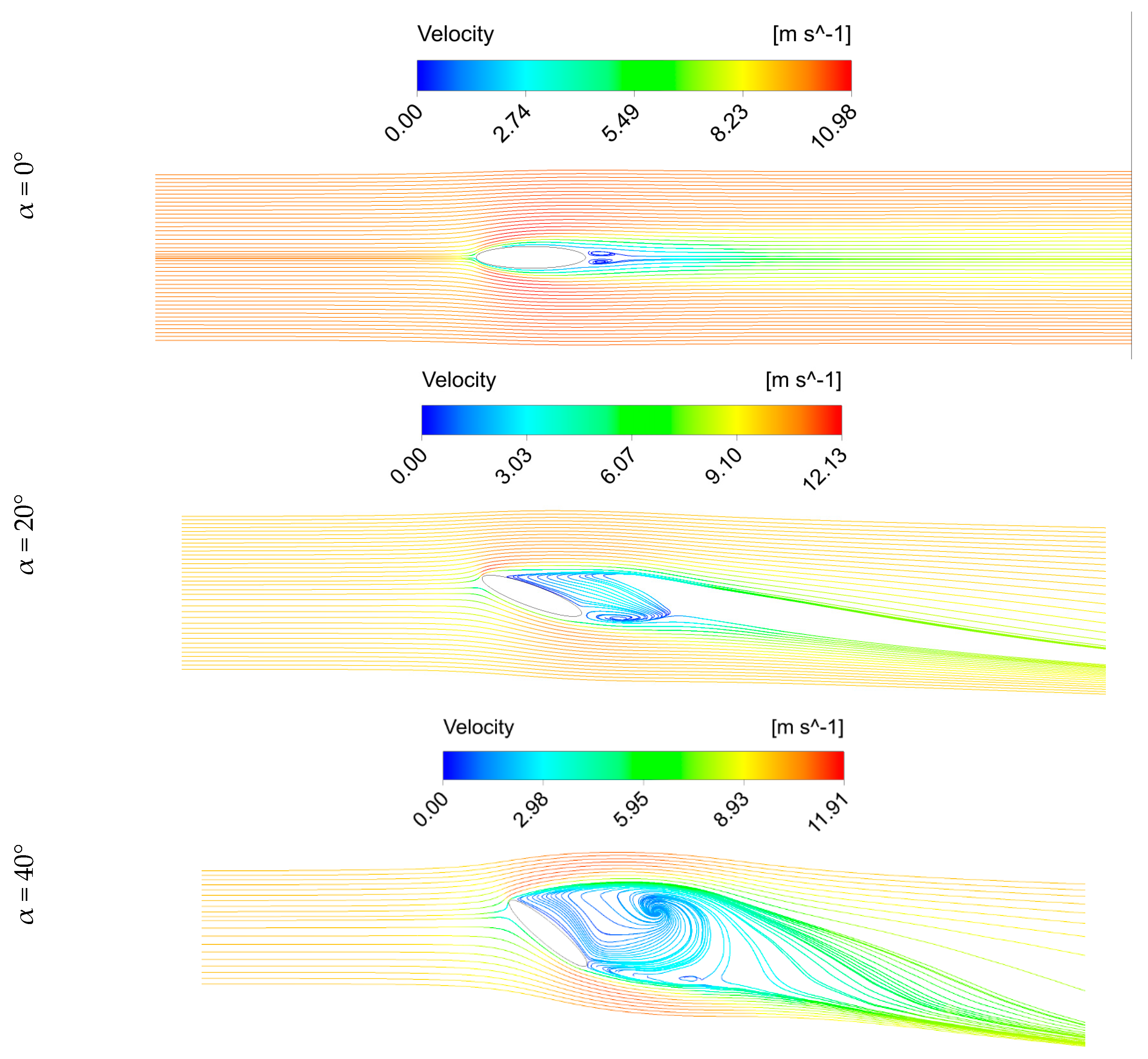
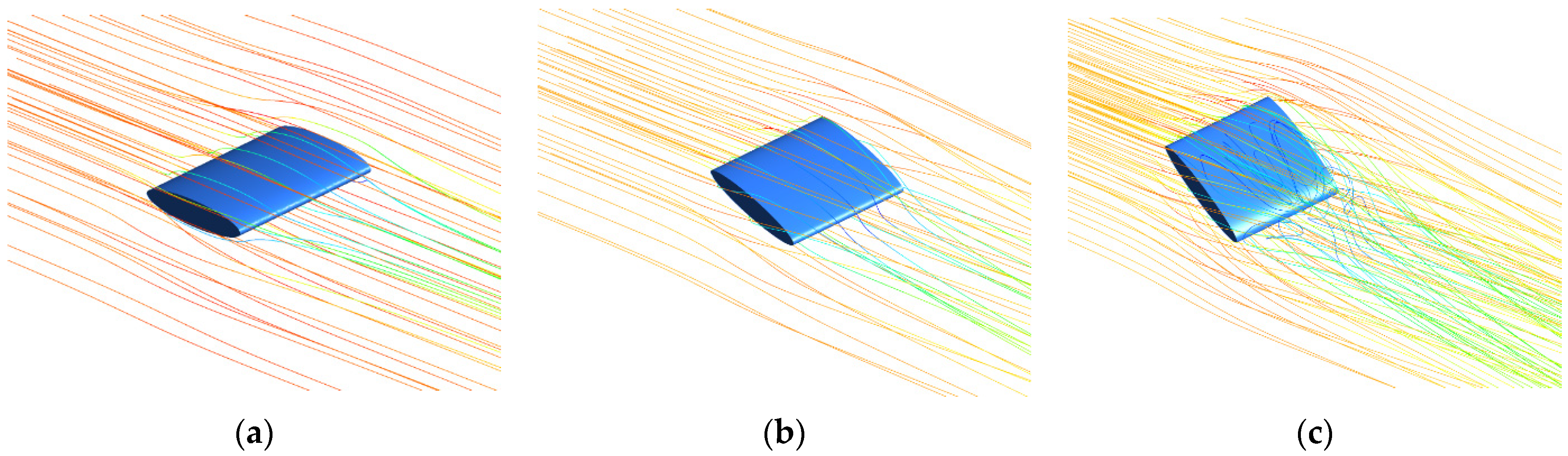
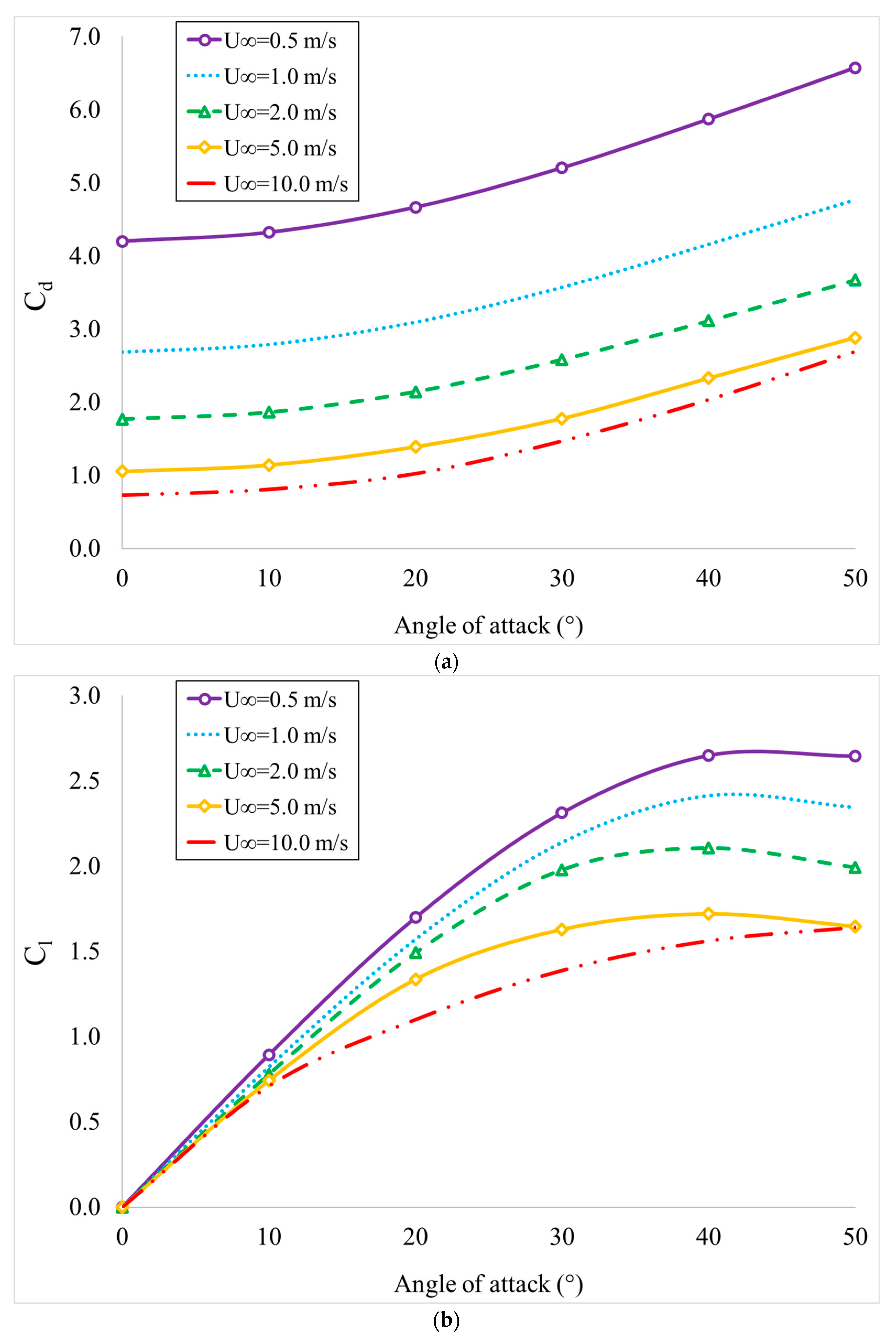
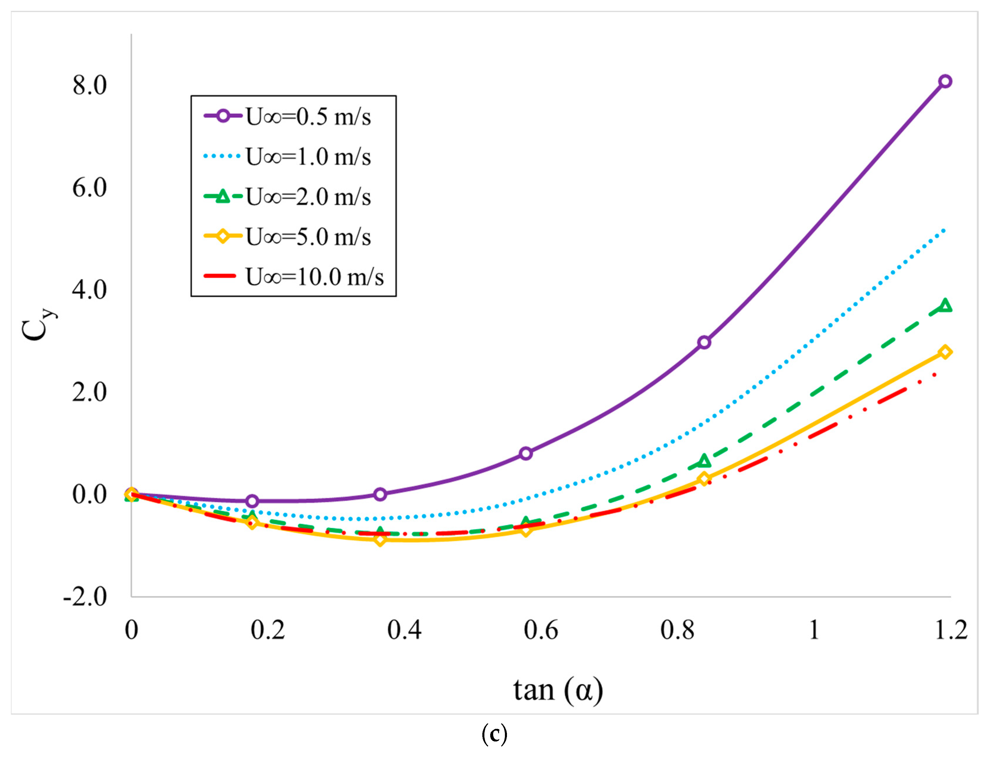
3.1. CFD Results
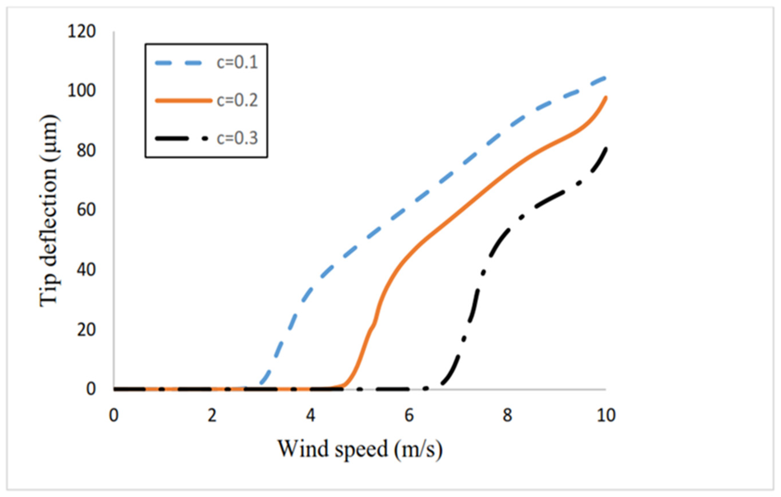
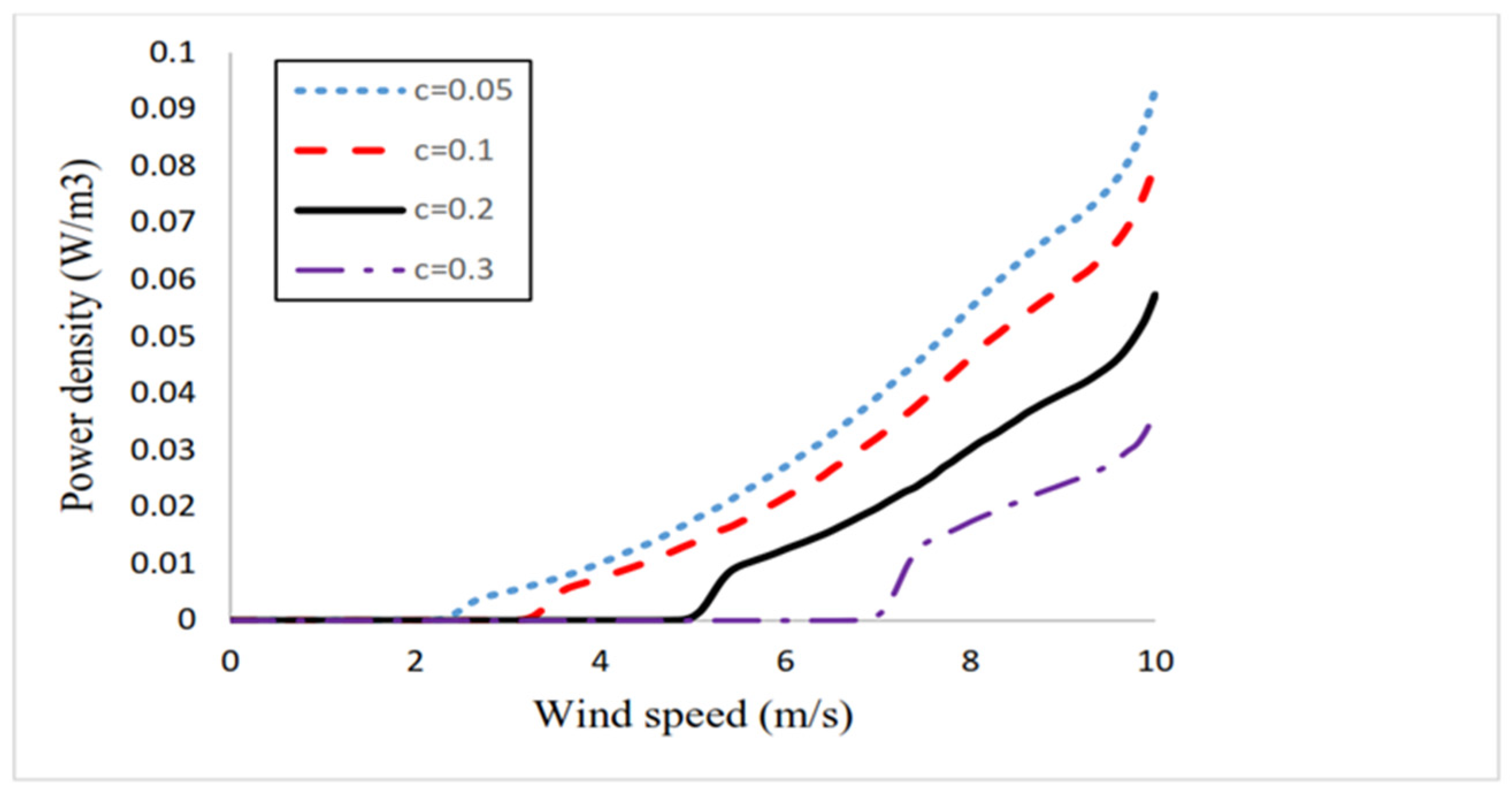
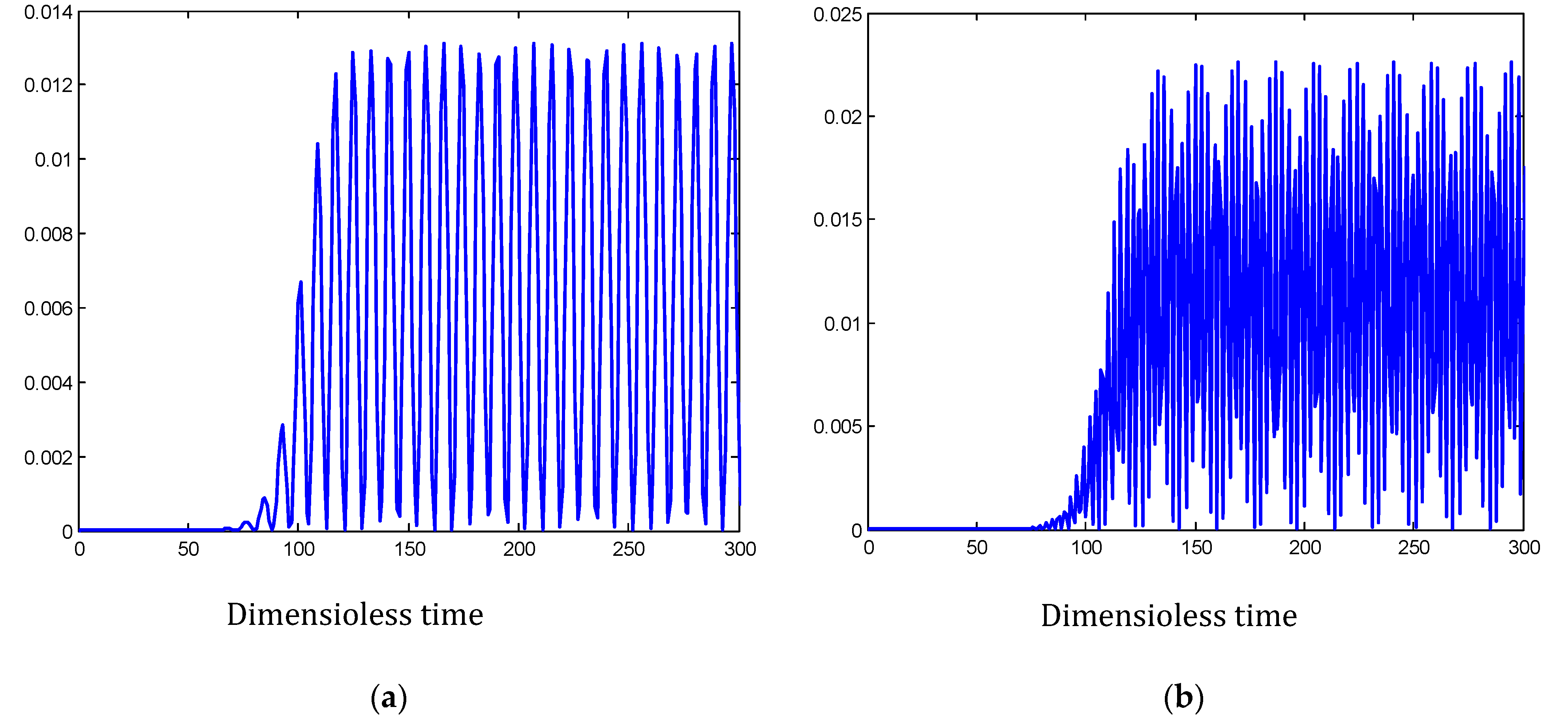
3.2. Galloping Effect
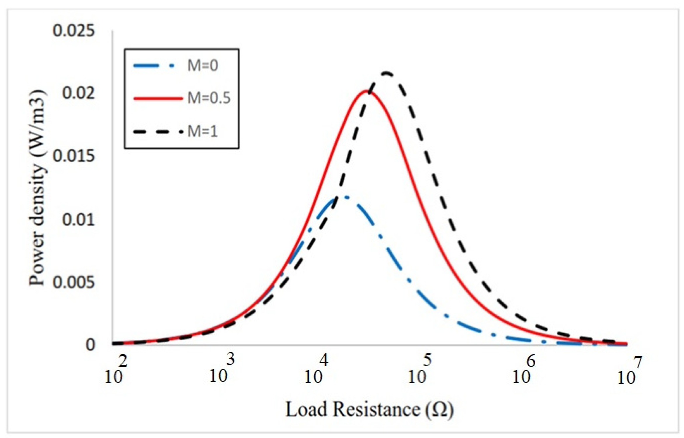
3.3. Load Resistance
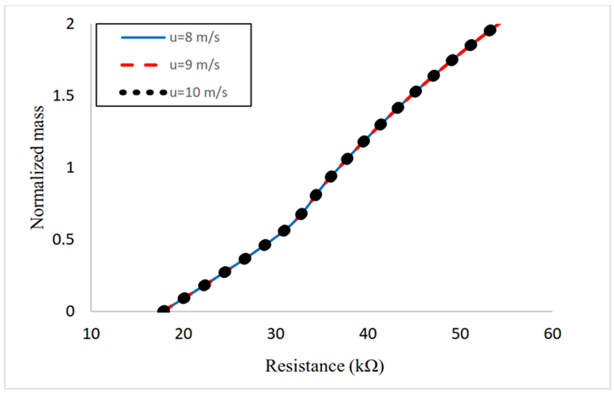
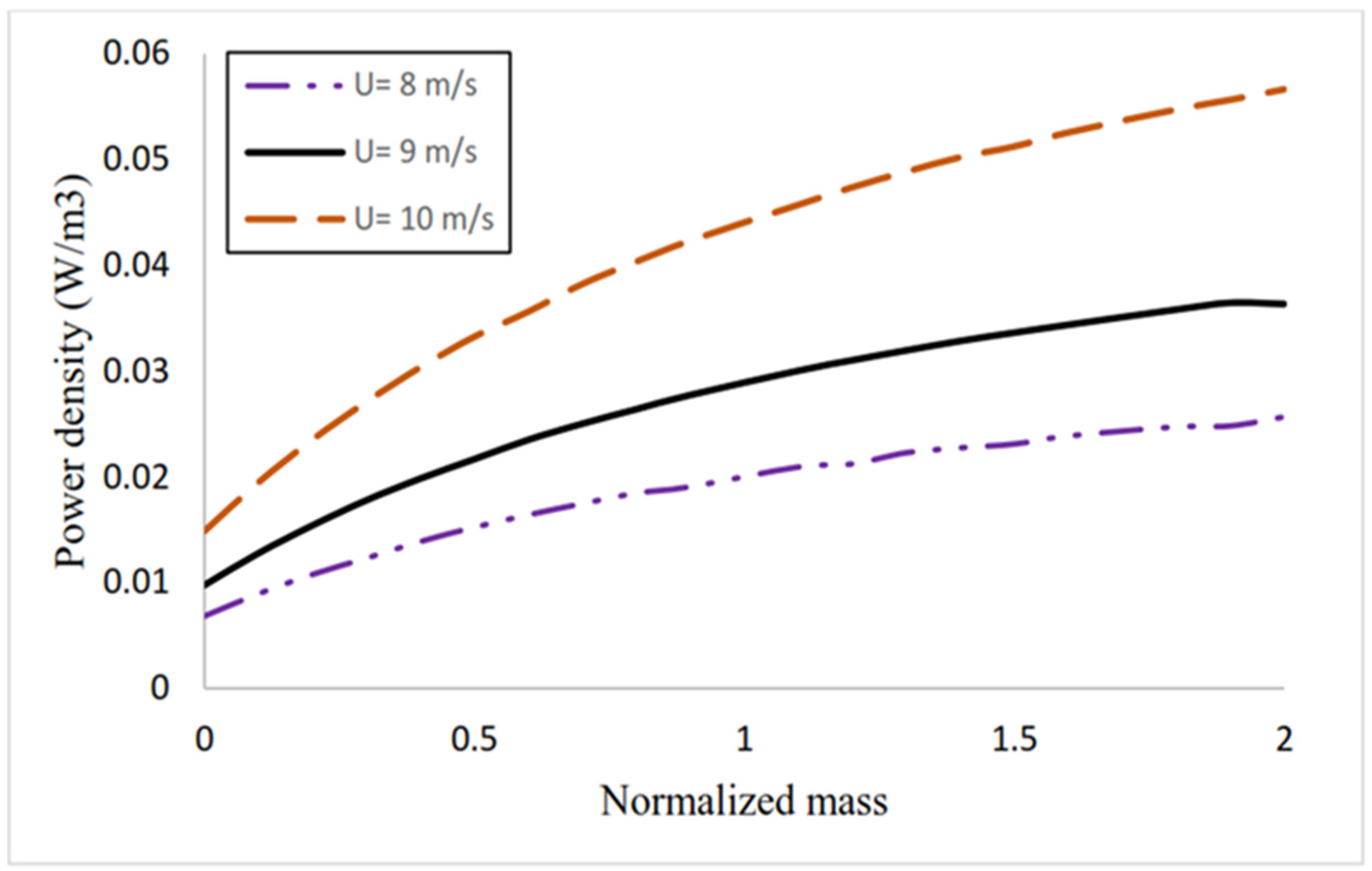
3.4. Elliptical Cylinder Mass Effect
4. Conclusions
Author Contributions
Funding
Institutional Review Board Statement
Informed Consent Statement
Data Availability Statement
Conflicts of Interest
References
- Yang, Z.; Erturk, A.; Zu, J. On the efficiency of piezoelectric energy harvesters. Extrem. Mech. Lett. 2017, 15, 26–37. [Google Scholar] [CrossRef]
- Ambia, F.; Lereoux, X.; Harouri, A.; Lefeuvre, E. A Novel Silicon on Glass Electrostatic MEMS for Energy Harvesting in Leadless Pacemakers. In Proceedings of the 21st International Conference on Micro and Nanotechnology for Power Generation and Energy Conversion Applications, Salt Lake City, UT, USA, 12–15 December 2022. [Google Scholar]
- Akbari, M.; Karimzadeh, A. Dynamic behavior analysis of piezoelectric flow micro sensors and corresponding linear working domain. Sharif J. Mech. Eng. 2023, 39, 47–53. [Google Scholar]
- Takei, F.; Cooray, N.F.; Yoshida, K.; Yoshida, H.; Ebisu, K.; Suzuki, S.; Sawatari, N. Development of prototype micro fuel cells for mobile electronics. Fujitsu Sci. Tech. J. 2005, 41, 191–200. [Google Scholar]
- Do, J.-S.; Yu, S.-H.; Cheng, S.-F. Preparation and characterization of thick-film Ni/MH battery. Biosens. Bioelectron. 2004, 20, 61–67. [Google Scholar] [CrossRef] [PubMed]
- Wu, Y.; Ma, Y.; Zheng, H.; Ramakrishna, S. Piezoelectric materials for flexible and wearable electronics: A review. Mater. Des. 2021, 211, 110164. [Google Scholar] [CrossRef]
- Roy, S.; Wasekul Azad, A.N.M.; Baidya, S.; Khorshed Alam, M. Powering solutions for biomedical sensors and implants inside the human body: A comprehensive review on energy harvesting units, energy storage, and wireless power transfer techniques. IEEE Trans. Power Electron. 2022, 37, 12237–12263. [Google Scholar] [CrossRef]
- Maamer, B.; Boughamoura, A.; Fath El-Bab, A.M.R.; Francis, L.A.; Tounsi, F. A review on design improvements and techniques for mechanical energy harvesting using piezoelectric and electromagnetic schemes. Energy Convers. Manag. 2019, 199, 111973. [Google Scholar] [CrossRef]
- Qian, F.; Liao, Y.; Zuo, L.; Jones, P. System-level finite element analysis of piezoelectric energy harvesters with rectified interface circuits and experimental validation. Mech. Syst. Signal. Process. 2021, 151, 107440. [Google Scholar] [CrossRef]
- Bedier, M.; Galayko, D. A 100nW Power Overhead Load Interface for Electrostatic Vibrational Energy Harvester with a High Biasing Voltage. Procedia Eng. 2016, 168, 1693–1697. [Google Scholar] [CrossRef]
- Cai, C.; Luo, B.; Liu, Y.; Fu, Q.; Liu, T.; Wang, S.; Nie, S. Advanced triboelectric materials for liquid energy harvesting and emerging application. Mater. Today 2022, 52, 299–326. [Google Scholar] [CrossRef]
- Wang, J.; Yurchenko, D.; Hu, G.; Zhao, L.; Tang, L.; Yang, Y. Perspectives in flow-induced vibration energy harvesting. Appl. Phys. Lett. 2021, 119, 100502. [Google Scholar] [CrossRef]
- Karimzadeh, A.; Roohi, R.; Akbari, M. Size-dependent behavior of micro piezoelectric VIV energy harvester: Parametric study and performance analysis. Appl. Ocean Res. 2022, 127, 103296. [Google Scholar] [CrossRef]
- Li, Z.; Zhou, S.; Yang, Z. Recent progress on flutter—Based wind energy harvesting. Int. J. Mech. Syst. Dyn. 2022, 2, 82–98. [Google Scholar] [CrossRef]
- Javed, U.; Abdelkefi, A. Role of the galloping force and moment of inertia of inclined square cylinders on the performance of hybrid galloping energy harvesters. Appl. Energy 2018, 231, 259–276. [Google Scholar] [CrossRef]
- Ma, X.; Zhou, S. A review of flow-induced vibration energy harvesters. Energy Convers. Manag. 2022, 254, 115223. [Google Scholar] [CrossRef]
- Govardhan, R.; Williamson, C.H.K. Modes of vortex formation and frequency response of a freely vibrating cylinder. J. Fluid Mech. 2000, 420, 85–130. [Google Scholar] [CrossRef]
- Wang, J.; Zhang, C.; Hu, G.; Liu, X.; Liu, H.; Zhang, Z.; Das, R. Wake galloping energy harvesting in heat exchange systems under the influence of ash deposition. Energy 2022, 253, 124175. [Google Scholar] [CrossRef]
- Wen, Q.; He, X.; Lu, Z.; Streiter, R.; Otto, T. A comprehensive review of miniatured wind energy harvesters. Nano Mater. Sci. 2021, 3, 170–185. [Google Scholar] [CrossRef]
- Li, H.-T.; Ren, H.; Cao, F.; Qin, W.-Y. Improving the galloping energy harvesting performance with magnetic coupling. Int. J. Mech. Sci. 2023, 237, 107785. [Google Scholar] [CrossRef]
- Yang, Y.; Zhao, L.; Tang, L. Comparative study of tip cross-sections for efficient galloping energy harvesting. Appl. Phys. Lett. 2013, 102, 064105. [Google Scholar] [CrossRef]
- Tan, T.; Yan, Z. Analytical solution and optimal design for galloping-based piezoelectric energy harvesters. Appl. Phys. Lett. 2016, 109, 253902. [Google Scholar] [CrossRef]
- Sobhanirad, S.; Afsharfard, A. Improving application of galloping-based energy harvesters in realistic condition. Arch. Appl. Mech. 2019, 89, 313–328. [Google Scholar] [CrossRef]
- Shi, M.; Holmes, A.S.; Yeatman, E.M. Piezoelectric wind velocity sensor based on the variation of galloping frequency with drag force. Appl. Phys. Lett. 2020, 116, 264101. [Google Scholar] [CrossRef]
- Lai, Z.H.; Wang, J.L.; Zhang, C.L.; Zhang, G.Q.; Yurchenko, D. Harvest wind energy from a vibro-impact DEG embedded into a bluff body. Energy Convers. Manag. 2019, 199, 111993. [Google Scholar] [CrossRef]
- Zhao, D.; Hu, X.; Tan, T.; Yan, Z.; Zhang, W. Piezoelectric galloping energy harvesting enhanced by topological equivalent aerodynamic design. Energy Convers. Manag. 2020, 222, 113260. [Google Scholar] [CrossRef]
- Zhang, L.; Meng, B.; Xia, Y.; Deng, Z.; Dai, H.; Hagedorn, P.; Peng, Z.; Wang, L. Galloping triboelectric nanogenerator for energy harvesting under low wind speed. Nano Energy 2020, 70, 104477. [Google Scholar] [CrossRef]
- Huang, D.; Han, J.; Li, W.; Deng, H.; Zhou, S. Responses, optimization and prediction of energy harvesters under galloping and base excitations. Commun. Nonlinear Sci. Numer. Simul. 2023, 119, 107086. [Google Scholar] [CrossRef]
- Chen, S.; Wang, C.H.; Zhao, L. A two-degree-of-freedom aeroelastic energy harvesting system with coupled vortex-induced-vibration and wake galloping mechanisms. Appl. Phys. Lett. 2023, 122, 063901. [Google Scholar] [CrossRef]
- Chen, S.; Zhao, L. A quasi-zero stiffness two degree-of-freedom nonlinear galloping oscillator for ultra-low wind speed aeroelastic energy harvesting. Appl. Energy 2023, 331, 120423. [Google Scholar] [CrossRef]
- Fleck, N.A.; Muller, G.M.; Ashby, M.F.; Hutchinson, J.W. Strain gradient plasticity: Theory and experiment. Acta Metall. Mater. 1994, 42, 475–487. [Google Scholar] [CrossRef]
- McFarland, A.W.; Colton, J.S. Role of material microstructure in plate stiffness with relevance to microcantilever sensors. J. Micromech. Microeng. 2005, 15, 1060. [Google Scholar] [CrossRef]
- Lam, D.C.C.; Yang, F.; Chong, A.C.M.; Wang, J.; Tong, P. Experiments and theory in strain gradient elasticity. J. Mech. Phys. Solids 2003, 51, 1477–1508. [Google Scholar] [CrossRef]
- Mindlin, R.D.; Tiersten, H.F. Effects of couple-stresses in linear elasticity. Arch. Ration. Mech. Anal. 1962, 11, 415–448. [Google Scholar] [CrossRef]
- Yang, F.; Chong, A.C.M.; Lam, D.C.C.; Tong, P. Couple stress based strain gradient theory for elasticity. Int. J. Solids Struct. 2002, 39, 2731–2743. [Google Scholar] [CrossRef]
- Li, Z.; He, Y.; Lei, J.; Guo, S.; Liu, D.; Wang, L. A standard experimental method for determining the material length scale based on modified couple stress theory. Int. J. Mech. Sci. 2018, 141, 198–205. [Google Scholar] [CrossRef]
- Romanoff, J.; Reddy, J.N. Experimental validation of the modified couple stress Timoshenko beam theory for web-core sandwich panels. Compos. Struct. 2014, 111, 130–137. [Google Scholar] [CrossRef]
- Karimzadeh, A.; Ahmadian, M.T.; Firoozbakhsh, K.; Rahaeifard, M. Vibrational analysis of size-dependent rotating micro-rings. Int. J. Struct. Stab. Dyn. 2017, 17, 1771012. [Google Scholar] [CrossRef]
- Thai, T.Q.; Zhuang, X.; Rabczuk, T. Curved flexoelectric and piezoelectric micro-beams for nonlinear vibration analysis of energy harvesting. Int. J. Solids Struct. 2023, 264, 112096. [Google Scholar] [CrossRef]
- He, Z.; Zhang, G.; Chen, X.; Cong, Y.; Gu, S.; Hong, J. Elastic wave harvesting in piezoelectric-defect-introduced phononic crystal microplates. Int. J. Mech. Sci. 2023, 239, 107892. [Google Scholar] [CrossRef]
- Karimzadeh, A.; Roohi, R.; Akbari, M. Piezoelectric wind energy harvesting from vortex-induced vibrations of an elastic beam. Sci. Iran 2023, 30, 77–89. [Google Scholar]
- Abdelkefi, A.; Najar, F.; Nayfeh, A.H.; Ben Ayed, S. An energy harvester using piezoelectric cantilever beams undergoing coupled bending–torsion vibrations. Smart Mater. Struct. 2011, 20, 115007. [Google Scholar] [CrossRef]
- Rao, S.S. Vibration of Continuous Systems; John Wiley & Sons: Hoboken, NJ, USA, 2019. [Google Scholar]
- Rahaeifard, M.; Ahmadian, M.T.; Firoozbakhsh, K. Vibration analysis of electrostatically actuated nonlinear microbridges based on the modified couple stress theory. Appl. Math. Model. 2015, 39, 6694–6704. [Google Scholar] [CrossRef]
- Akaydin, H.D.; Elvin, N.; Andreopoulos, Y. The performance of a self-excited fluidic energy harvester. Smart Mater. Struct. 2012, 21, 025007. [Google Scholar] [CrossRef]
- Leontini, J.S.; Griffith, M.D.; Lo Jacono, D.; Sheridan, J. The flow-induced vibration of an elliptical cross-section at varying angles of attack. J. Fluids Struct. 2018, 78, 356–373. [Google Scholar] [CrossRef]
- Naudascher, E.; Rockwell, D. Flow-Induced Vibrations: An Engineering Guide; Courier Corporation: Chelmsford, MA, USA, 2012; 432p. [Google Scholar]


| Dimensions and Properties | Base Beam (Silicon) [44] | Piezoelectric Layer (PZT-5A) [45] | Other Parameters |
|---|---|---|---|
| Length | 500 | 500 | --- |
| Width | 50 | 50 | --- |
| Thickness | 5 | 1 | --- |
| Density | 2332 | 7800 | --- |
| Young modulus | 150 | 66 | --- |
| Poisson’s ratio | 0.23 | 0.35 | --- |
| Length scale parameter | 0.27 | --- | --- |
| Permittivity at constant strain | --- | 13.28 | --- |
| Piezoelectric stress coefficient | --- | −12.54 | --- |
| Fluid density | --- | --- | 1.225 |
| Fluid viscosity (Pa.s) | 0.00001812 | ||
| Elliptical cylinder big, small diameters | --- | --- | 500,100 |
| Elliptical cylinder length | --- | --- | 500 |
Disclaimer/Publisher’s Note: The statements, opinions and data contained in all publications are solely those of the individual author(s) and contributor(s) and not of MDPI and/or the editor(s). MDPI and/or the editor(s) disclaim responsibility for any injury to people or property resulting from any ideas, methods, instructions or products referred to in the content. |
© 2023 by the authors. Licensee MDPI, Basel, Switzerland. This article is an open access article distributed under the terms and conditions of the Creative Commons Attribution (CC BY) license (https://creativecommons.org/licenses/by/4.0/).
Share and Cite
Karimzadeh, A.; Akbari, M.; Roohi, R.; Amiri, M.J. Dynamic Behavior of Galloping Micro Energy Harvester with the Elliptical Bluff Body Using CFD Simulation. Sustainability 2023, 15, 12187. https://doi.org/10.3390/su151612187
Karimzadeh A, Akbari M, Roohi R, Amiri MJ. Dynamic Behavior of Galloping Micro Energy Harvester with the Elliptical Bluff Body Using CFD Simulation. Sustainability. 2023; 15(16):12187. https://doi.org/10.3390/su151612187
Chicago/Turabian StyleKarimzadeh, Ali, Masoud Akbari, Reza Roohi, and Mohammad Javad Amiri. 2023. "Dynamic Behavior of Galloping Micro Energy Harvester with the Elliptical Bluff Body Using CFD Simulation" Sustainability 15, no. 16: 12187. https://doi.org/10.3390/su151612187