Abstract
Heating furnaces fueled by fossil fuels are commonly utilized in oilfields to provide heat to the settling tank, which heats the layer of crude oil. However, this traditional heating method consumes a significant amount of oil and gas resources, resulting in low energy utilization and environmental pollution. As the water content of the extracted crude oil increases over time, the operating costs of the settling tanks also continue to increase. Therefore, it is crucial to develop and implement clean and efficient heating technologies to facilitate the efficient operation of settling tanks. This paper proposes a solar–gas combined heating technology for settling tanks. A simulation model for the solar–gas combined heating system for the settling tank is constructed, considering the overall perspective of the system. The simulation model analyzes the impact of the control strategy for the oil collection period of the settling tank on the system performance. This analysis covers various aspects including the heat collection of the solar collector, the heat supply of the gas boiler, and the heat storage and release of the phase-change heat storage tank. The results demonstrate that when the oil collection cycle is Scheme E (4:00–8:00), the collector achieves the highest annual cumulative heat collection, the gas boiler provides the lowest annual total heat supply, and the phase-change heat storage tank exhibits the highest heat storage and release efficiency. Over the course of the system’s 15 year service life, the settling tank solar–gas combined heating system saves 727,988.69 MJ of energy annually, resulting in total energy-saving costs of CNY 397,007. The dynamic investment payback period is estimated at 9.14 years, and the system reduces CO2 emissions by 753,069.8 kg.
1. Introduction
Currently, the majority of oilfields in China have entered the mid to late period of production, resulting in crude oil with a high water content of around 70% to 80% [1]. The energy consumption of oilfield combination stations is constantly increasing, putting significant pressure on production costs. In oilfield production, gravity settling tanks are widely used for oil-water separation of oilfield wastewater to achieve crude oil recovery [2]. However, due to the high viscosity and poor flowability of crude oil, a heat-tracing coil is utilized in practical production to prevent the condensation of the crude oil layer. This coil is placed at the oil-water interface of the settling tank to heat the oil layer, improve its flowability, and ensure the smooth recovery of crude oil [3]. Currently, oilfields generally use heating furnaces to burn fossil fuels as a heat source for heating the crude oil layer in settling tanks. This traditional heating method consumes a large amount of oil and gas resources, has low energy utilization efficiency, and contributes to environmental pollution. The extraction, processing, gathering, and storage of crude oil require a large amount of energy, and the crude oil used in the oil production and processing process accounts for 30% of the total oil production annually [4]. Given the growing scarcity of conventional fossil fuels, it is crucial to harness environmentally friendly and sustainable renewable energy sources and develop alternative heating methods for oilfield settling tanks.
Solar energy, as a renewable energy source, offers a clean, pollution-free solution with abundant resources [5]. It serves as a significant replacement for fossil energy and helps address the energy crisis. However, due to the intermittent and fluctuating nature of solar energy, it is difficult for a solar heating system relying on a single energy source to continuously meet the demand of the energy consumption side. To ensure a stable heating system, traditional gas heating methods are still required as a supplement. Currently, solar energy technology is accelerating its penetration into various fields, such as people’s livelihoods, industry, and national defense, and solar multi-energy complementary technology will be an important support for accelerating the green transformation of the energy industry. Solar heating technology has been widely applied in heavy oil thermal recovery, crude oil heating, and crude oil gathering and transportation. In terms of heavy oil thermal recovery, Berry Corporation (Bakersfield, CA, USA) [6] built a solar plant for the enhanced thermal recovery of crude oil in CA, USA. Chevron Corporation(San Ramon, CA, USA) [7,8] proposed the concept of using heliostats for solar-concentrating heat collection to generate high-temperature and high-pressure steam for the thermal recovery of heavy oil. Bighsouce Company(USA) [9] in the United States has built a 29 MW tower steam generator using the tower heating method, which can inject the generated high-temperature and high-pressure steam into the underground oil storage layer for heating in order to increase the pressure of the oil storage layer and reduce the viscosity of the crude oil. GlassPoint Company(Fremont, USA)used trough- and tower-type concentrating heat collection systems to produce steam for heavy oil thermal recovery [10], and the system can produce 1.4 × 10⁴ tons of steam per year, reducing natural gas consumption by 80% compared to traditional methods. Research on the application of solar thermal recovery technology for heavy oil in China started relatively late, mostly with theoretical exploration [11,12]. In terms of crude oil heating, Qian et al. [13] proposed a solar-wastewater source heat pump system combined with the characteristics of oilfield heat use, using solar energy and oily wastewater residual heat to jointly heat crude oil, and established a simplified mathematical model of the system. Li et al. [14] applied a solar collector-assisted electric heating device in North China Oilfield to accompany the heat of crude oil in storage tanks and oil-gathering pipelines to achieve the purpose of reducing energy consumption and pollution. Using Matlab/Simulink software, Pei et al. [15] established a mathematical model of a solar collector coupled with a high-temperature water source heat pump for the joint heating of crude oil and analyzed the operating characteristics of the solar energy, heat pump joint heating system, and its economic benefits. Xu et al. [16] compared and evaluated the operating effects of solar-assisted crude oil heating devices, water jacket heating furnaces, and petroleum explosion-proof electromagnetic heaters in Ansai Oilfield. The results showed that solar-assisted crude oil heating devices have significant economic advantages and environmental benefits. The total cost of the device after 10 years of operation is about CNY 280,000, which is 44% and 69% lower than water-jacket-heating furnaces and petroleum explosion-proof electromagnetic heaters, respectively. Hao et al. [17] designed a photovoltaic photothermal integrated crude oil heating system suitable for oilfield wellheads, which ensures the system’s daytime heat consumption while achieving long-term crude oil heating at night, saving 2.1 × 10⁴ m3 of natural gas annually. Mammadov [18] from Azerbaijan used a solar cell solar collector to preheat an oil–water mixture to the dehydration temperature in crude oil dehydration treatment, achieving chemical demulsification of crude oil. In terms of crude oil gathering and transportation, Lasich et al. [19] applied solar heating technology to crude oil pipelines in countries such as Oman and Indonesia, achieving an increase in transportation volume and pipeline tracing, reducing the operation and maintenance costs of oil companies, and confirming the reliability of solar heating systems. Liaohe Oilfield [20,21,22] collaborated with domestic universities to design a solar heating energy-saving system for crude oil gathering and transportation. The system adopts a working mode of solar energy supplemented by natural gas heating, which can reduce natural gas consumption by 30%.
Based on the above research, existing research mainly focuses on the engineering application practice or simplified theoretical analysis of solar heating systems and relates to the energy matching characteristics and system efficiency performance of the solar–gas combined heat and power systems applied to oilfields have not been studied in depth, which restricts the development and application of this new heating method. Therefore, this article carries out research on the energy flow characteristics of the combined solar–gas heating system for settling tanks to improve the energy utilization rate, economic and environmental benefits of the system, and further realize energy saving and consumption reduction. Fu [23] and Ai [24] have also conducted beneficial explorations in the calculation of the thermal load on crude oil storage tanks and the matching calculation of the system heat collection area.
The above research can provide a reference for the research on solar–gas heating systems for settling tanks. Based on the actual problems faced during the operation of the settling tanks in the joint station and the green low-carbon, energy-saving, and consumption-reduction targets implemented by the oilfield, a combined solar–gas heating system for the settling tanks is established, and combined with the system simulation means, the economic and environmental protection benefits are evaluated based on the dynamic operation characteristics of the system, and find the appropriate system control strategy. As a new heating method, the settling tank solar–gas combined heating system is expected to become an important driving force for energy conservation and efficiency creation in oilfields. This paper takes the 3000 m3 settling tank of a certain oil production plant in Daqing Oilfield as an example, and based on the TRNSYS simulation model of the solar–gas combined heating system of the settling tank, analyzes the impact of the settling tank oil collection cycle on the system’s heat collection, heating, and storage. It explores the monthly variation patterns of parameters, such as the solar energy guarantee rate, the average temperature of the original oil layer of the settling tank, the temperature of the phase-change heat storage tank, and the solid–liquid ratio. The system’s annual energy savings, total energy-saving costs, and other performance benefits were evaluated. The research results will help the development of oilfield solar multi-energy complementary heating technology and provide practical solutions to achieve energy saving and efficiency in oilfields.
2. Research Method
2.1. System Composition and Operating Principles
The provided diagram, depicted in Figure 1, illustrates the solar–gas combined heating system for the designed settling tank. The system is primarily composed of essential components, such as the settling tank, solar collector, gas boiler, phase-change heat storage tank, environmental monitoring system, and temperature control system.
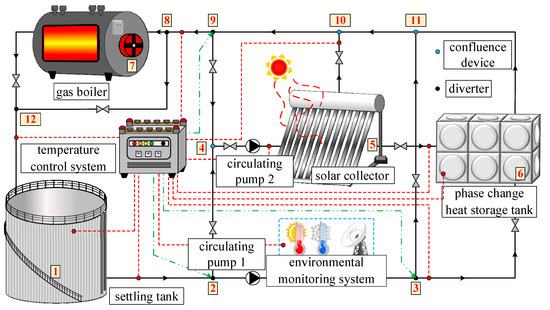
Figure 1.
Schematic diagram of solar–gas combined heating system for settling tank.
This system can achieve six sub-system operation modes: a separate solar heating system (1-2-4-5-10-8-12-1), a separate gas boiler heating system (1-3-11-8-7-12-1), a separate phase-change heat storage box heating system (1-3-6-11-10-9-8-12-1), a solar–phase-change combined heating system (1-2-4-5-6-10-10-10-9-8-12-1), a solar–gas combined heating system (1-2-4-5-10-8-7-12-1), a solar–phase-change–gas combined heating system (1-2-4-5-6-11-10-10-9-8-7-12-1) and a solar–phase-change thermal storage cycle system (5-6-11-10-10-9-4-5). This heating system adopts the principle of prioritizing solar heating when the solar energy is insufficient, and a phase-change heat storage tank is used for heating. But when neither of them can meet the energy demand, a gas boiler is turned on for auxiliary heating. The solar collector converts solar radiation into thermal energy, and its internal heat-transfer fluid carries out the heat for the heating and temperature maintenance work of the settling tank. The temperature control system monitors the temperature of the heat-transfer fluid inside the settling tank and at the outlet of the solar collector in real time. When there is excess heat, the heat-transfer fluid flows into the phase-change heat storage tank for heat storage. The temperature control system determines whether the phase-change heat storage tank storage/release mode is activated based on real-time operating conditions. The gas boiler is mainly used when the heat-transfer fluid is heated by solar collectors and a phase-change heat storage tank, but the temperature control system determines that its temperature still cannot meet the energy demand. At this time, the gas boiler starts to further heat the heat-transfer fluid to the target temperature. When solar radiation is weak at night and in rainy weather, and the solar collector cannot work during the daytime, the gas boiler also serves as the main heat source of the system. In addition, the solar phase-change heat storage cycle system is activated to store solar energy resources during this period for future utilization in two situations. First, when the fluid temperature in the settling tank meets the working requirements and the ambient temperature is high without further heating, and second, when the settling tank is in the inlet and outlet cycle, and the coil heating is not turned on.
2.2. System Thermodynamic Model
2.2.1. Solar Collector Model
- Solar radiation model [25]:
- Thermal efficiency of solar collector [26]:
- Heat balance equation of solar collector:
2.2.2. Phase-Change Heat Storage Tank Model
2.2.3. Circulating Pump Model
2.3. Establishment of Simulation Platform for Solar–Gas Combined Heating System of Settling Tank
The geometric structure of the settling tank is shown in Figure 2a. It can be seen that the main components of the settling tank include a central pipe, liquid distribution pipe, water-collecting pipe, oil-collecting tank, heat-tracing coil, oil outlet pipe, water outlet pipe, and other auxiliary components such as silt removal and sludge discharge. Figure 2b is the geometric structure diagram of the heat-tracing coil of the settling tank. The heat-tracing coil is formed by bending and welding a long tube many times, and its coil spacing is different.
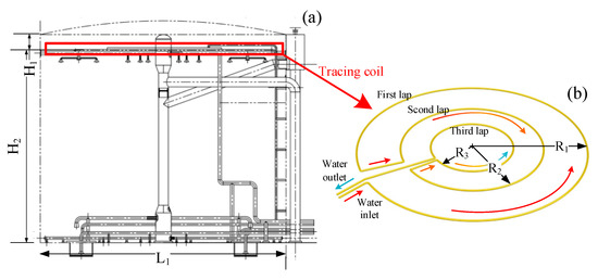
Figure 2.
The geometric structure of the (a) settling tank and (b) heat-tracing coil.
It is known that the height (H1 + H2) of the settling tank is 14.06 m, and the width (L1) is 15.8 m. Basic materials are filled at the bottom of the tank with a thickness of 1 m (from top to bottom are asphalt sand, sand, and backfill soil with a thickness of 0.2 m, 0.3 m, and 0.5 m, respectively). The height of the tracing coil from the top of the settling tank (H1) is 0.8 m, and its diameter is 0.06 m. The three-coil radii are 6 m (R1), 3.75 m (R2), and 2.2 m (R3), respectively.
2.3.1. Initial Working Conditions of Settling Tank
- Physical parameters of crude oil
- Density [27]:
- Thermal conductivity [28]:
- Specific heat:
- Viscosity:
- Initial condition
The working temperature of the settling tank is 40 °C, and the thickness of the steel plate and insulation material of the tank wall is 0.01 m and 0.08 m, respectively. The outdoor ambient temperature is −20 °C, and the wind speed is 13 m/s. The known condensation point of crude oil is 28 °C, the stagnant point is 32 °C, the surface temperature of the trace coil is 80 °C, and the base material bottom temperature is 5 °C. The design heat load of the settling tank is 111.6 kW. Table 1 shows the physical parameters of related materials.

Table 1.
Physical parameters of related materials.
2.3.2. System Design Parameters
- Main device parameters of the system
The design of solar collectors mainly refers to the relevant national standards and manual [29,30].
where Asolar is the collector’s collecting area, m2; Qtank is the heat load of the settling tank, W; f is the local solar energy guarantee rate (refer to Appendix A of the “Solar Heating Engineering Technical Standard (GB50495-2019)” and select the guarantee rate as 30%); JT is the annual average daily solar radiation of the local collector inclination (refer to Appendix A of the “Technical Standard for the Application of Solar Water Heating System for Civil Buildings (GB50364-2018)”, set the collector plane inclination as 45°, and select the value of the annual average daily solar radiation); ηave is the annual average collector efficiency, %; ηL is the average daily loss rate of solar system pipelines and heat storage devices, %. By calculation, the solar collector area of the system is 349.86 m2. It is known that each group of vacuum tube solar collectors is composed of 50 vacuum tubes, and the effective heat collection area of each group of collectors is 7.8 m2, so a total of 45 groups of solar collectors are needed. Among them, relevant physical property parameters of heat-transfer fluid materials are as follows (Table 2).
Table 2.
Physical parameters of heat-transfer fluid.
The physical parameters of phase-change materials in phase-change heat storage tank are shown as follows (Table 3).
Table 3.
Physical parameters of phase-change materials.
The heat load of the settling tank in this system is 111.6 kW, so the WNS0.35-0.7/95 horizontal gas boiler is selected for auxiliary heating. The specific parameters are as follows (Table 4).
Table 4.
WNS0.35-0.7/95 horizontal gas boiler parameters.
The models of circulating pump 1 and circulating pump 2 are vertical IRG50-125A-1.1 and vertical IRG50-125(I)A-2.2. The model parameters are as follows (Table 5).
Table 5.
Circulating pump parameter.
- System meteorological parameters
The TRNSYS software 18.2 version Type15-2 component was used to read the typical annual meteorological parameters from the Meteonorm 8.0 database in Daqing. The total solar radiation and environmental temperature data for Daqing throughout the year are shown in Figure 3. Daqing is located in a high-latitude region with abundant solar resources, with the strongest solar radiation in spring and autumn. Its direct normal radiation per year is 1408 kWh/m2, and the lowest temperature in winter is as low as −26.4 °C.
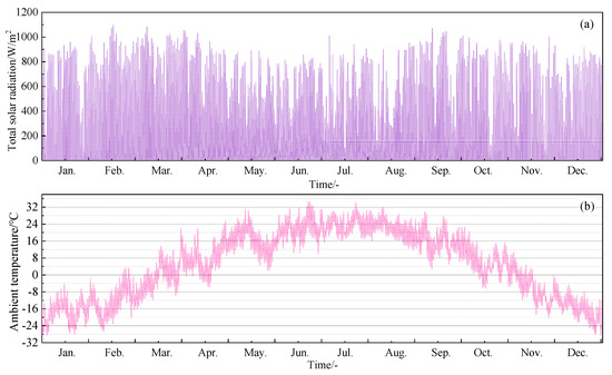
Figure 3.
Annual (a) total solar radiation and (b) ambient temperature in Daqing.
2.4. TRNSYS Simulation Model of the System
2.4.1. Construction of Model
Figure 4 shows the solar–gas combined heating system of the settling tank using the TRNSYS software. Its components are connected by connecting wires to realize real-time signal communication.
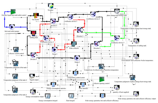
Figure 4.
Simulation model of solar–gas combined heating system for settling tank.
2.4.2. System Model Verification
In order to verify the reliability of the simulation system, experimental equipment is used to verify the heating process of the phase-change heat storage tank and settling tank in the solar–gas combined heating system of the settling tank. Figure 5 shows the connection diagram of the experimental equipment, in which the sedimentation tank, phase-change heat storage tank, liquid replenishment tank, and circulating pump are connected in series. The diameter of the tank is 0.6 m, and the height is 0.9 m. Figure 5 shows the average temperature of the settling tank and phase-change heat storage tank. The initial temperatures of the settling tank and phase-change heat storage tank are 10 °C and 57 °C, respectively, and the flow rate of the circulating pump is 1.3 m3/h. The average errors of the average temperature of the phase-change heat storage tank and settling tank after 4 h operation are 5.6% and 7.39%, respectively, which is reasonable and can verify the accuracy of the heating system operation in this paper.
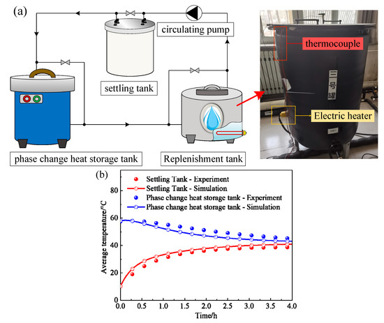
Figure 5.
Experimental system diagram and model verification: (a) schematic diagram of experimental equipment connection; (b) model validation.
2.4.3. System Control Mode
Due to the real-time dynamic change in system energy demand, in order to realize flexible subsystem scheduling and efficient utilization of solar energy resources, the system operation control is designed as follows:
- In order to maintain the appropriate operating temperature of the settling tank, the heat-tracing coil is monitored when the average temperature of the crude oil layer at the top of the tank is lower than 39 °C, and the heating coil is closed when the temperature is higher than 40.5 °C. In order to prevent the temperature of the settling tank from being too high, the heating of the settling tank should be stopped when the temperature of the crude oil layer exceeds 43 °C, and the solar–phase-change heat storage cycle system should be started.
- The collector opening and closing control is coordinated by the collector opening time control and collector temperature difference monitoring. When the daily time is between 6:00 and 18:00, the collector opening time control requirements can be met; when the temperature difference between the heat-transfer fluid at the outlet of the collector and the average temperature difference between the oil layer temperature is more than 10 °C, the collector needs to be started. When the temperature difference is reduced to less than 5 °C, the collector is closed.
- The control of the phase-change heat accumulator is mainly divided into three modes: heat storage, heat release, and by-pass.
- Heat storage mode: In order to ensure that the oil reservoir temperature meets the working requirements, an oil reservoir temperature above 40.5 °C is a necessary prerequisite for the heat storage mode to be opened. When the temperature of the heat-transfer fluid at the outlet of the collector is higher than the temperature of the phase-change heat storage tank, the phase-change heat storage is opened, and when the temperature difference is lower than 8 °C, the phase-change heat storage is closed.
- Heat release mode: The heat release process of the phase-change heat storage tank can be subdivided into daytime and solar collector combined with heating and night heat release. When the temperature of the crude oil layer is lower than 39 °C, and if the daytime collector is opened when the heat-transfer fluid temperature at the collector outlet is lower than 8 °C of the phase-change storage tank, the solar-phase-change joint heating mode is opened. If the collector is closed at night, the temperature of the phase-change heat storage tank should be compared with the temperature of the heat-transfer fluid at the outlet of the settling tank. If the temperature difference between the two is greater than 3 °C, the phase-change heat release mode is on; when the temperature difference is less than 1 °C, the phase-change heat release mode is closed.
- By-pass mode: The by-pass mode is mainly opened when the phase-change heat storage tank cannot meet the requirements of heat storage/release. The purpose of this mode is to ensure that the heat generated by the solar collector can meet the requirements of the settling tank first.
- The opening control of the gas boiler mainly depends on the average temperature of the crude oil layer. When the heat-transfer fluid is heated by the solar collector or the phase-change storage tank, the average temperature of the crude oil layer is still below 39 °C, and at night or under special weather conditions when the solar collector and the phase-change storage tank cannot work, the gas boiler is opened for heating.
- In order to fit the working process of the actual settling tank, periodic liquid inlet and discharge control have been designed. The settling period of the settling tank is set to 12 h, in which the time of inlet and discharge of liquid is 2 h, and the settling time is 8 h. The tracing coil is closed during the inlet and discharge of the liquid, and the solar–phase-change heat storage circulation system can be operated independently during this period for heat storage.
3. Results and Discussion
3.1. The Influence of Settling Tank Receiving Period on System Operating Characteristics
When the settling tank completes one oil collection cycle, since no new oil layer is formed after the end of the previous oil collection cycle, the heating effect of the thin oil layer is not obvious, and the crude oil has strong fluidity after heating and viscosity reduction during oil collection. Thus, the heating of the heating coil is not opened in the early and late oil collection cycle, but only in the middle stage of oil formation. Therefore, the time of the oil collection cycle is related to whether the solar energy resources can be fully utilized, and the arrangement of the oil collection cycle inevitably affects the overall operation characteristics of the heating system. The possible oil collection cycle schemes are listed in Table 6, where “1” represents the period of oil formation and collection, and two oil collection cycles can be completed during the daily operation of the settling tank. Plan A is taken as an example to introduce the operational arrangement in Table 6, where 2:00–14:00 is the first oil discharge period, in which 2:00–4:00 is the period when the settling tank enters the liquid, during which the crude oil layer is formed and accumulated; 4:00-12:00 is the operating period for heating coils, which heats the crude oil layer; 12:00–14:00 is the oil-receiving period of the settling tank. The heating of the tracing coil stops and the crude oil is discharged. The first oil discharge cycle ends, and then the second oil discharge cycle starts (14:00–2:00). The analysis found that the effect of illumination on multiple groups of schemes in the table is similar, such as schemes A and I. In order to save calculation time, five schemes, namely A, B, C, E, and K, are summarized in Table 6, and the simulation operation of the solar–gas combined heating system of the settling tank is carried out for one year, with its time step is 0.05 h.
Table 6.
Periodic oil collection schedule of the settling tank.
As shown in Figure 6a, the total annual heat collection of the solar collectors during the implementation of the five oil-harvesting schemes is shown. Among them, the maximum annual cumulative heat collection of the collector in Scheme E (4:00–8:00) is 873.79 GJ, which is 5.2% (42.95 GJ), 3.3% (28.08 GJ), 2.1% (18.18 GJ), and 6.7% (56.91 GJ) higher than those of Schemes A, B, C, and K. Observing the oil-harvesting schemes of Scheme E and Scheme K (10:00–14:00), it was found that Scheme K had an oil-harvesting time arranged during the period of the strongest illumination from 10:00–14:00. At this time, the heating of the heat-tracing coil was turned off, and the solar phase-change heat storage cycle was activated. Due to the fact that the return water temperature of the collector after the heat-transfer fluid passes through the phase-change heat storage tank is higher than the return water temperature after passing through the settling tank, the heating capacity of the collector is limited under certain conditions, such as solar radiation and environmental temperature. The increase in the temperature of the heat-transfer fluid at the inlet of the collector leads to a decrease in the temperature difference between the inlet and outlet, thereby reducing the total heat collection of the collector. Figure 6b shows the solar collector efficiency in Scheme E and Scheme K. The solar energy collection efficiency of Scheme E is higher than that of Scheme K for each month. As the system operation time gradually increases, the solar energy collection efficiency of the collector also gradually increases. By October, the solar energy collection efficiency of the collector is the highest, with Scheme E and Scheme K having solar energy collection efficiency of 40.1% and 37.4%, respectively.
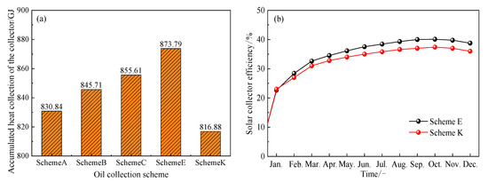
Figure 6.
(a) Accumulated heat collection of collectors with different oil recovery schemes (annual total); (b) the solar collector efficiency of Scheme E and K.
Figure 7 shows the cumulative heat collection for different months of the collectors in Scheme E and Scheme K. Observing the images, it was found that the monthly heat collection of solar collectors was influenced by solar radiation and has obvious seasonal characteristics. Observing the cumulative solar radiation curve of that month, it was found that the total solar radiation was the highest in spring. Both schemes had the highest cumulative heat collection in March, with a cumulative heat collection of 94.26 GJ and 86.67 GJ, respectively, which were significantly higher than in other months. In January and December of winter, the total solar radiation was weak, and the cumulative heat collection of both schemes was less than 40 GJ, resulting in a low solar energy guarantee rate.
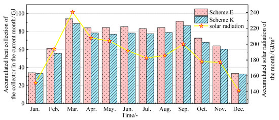
Figure 7.
Accumulated heat collection of schemes E and K collectors in different months.
As shown in Figure 8a, the total annual heating capacity of the gas boilers during the implementation of the five oil recovery schemes is shown. In contrast to the total annual heat collection of solar collectors, Scheme E has the lowest total annual heat supply of 741.35 GJ for gas boilers. Scheme K has the highest annual total heating capacity of 1047.28 GJ, which is 7.2% (70.38 GJ), 14.5% (132.66 GJ), 24.5% (206.36 GJ), and 41.3% (305.93 GJ) higher than those of Schemes A, B, C, and E, respectively. As shown in Figure 8b, the cumulative heating capacity of the gas boilers changes over time. By observing the curve, it was found that the cumulative heating volume slowly increased from April to September, indicating that the heating volume of gas boilers was relatively low during this period. The significant increase in the slope of the curve from January to March and from September to December proves that the system’s demand for gas boiler heating has increased.
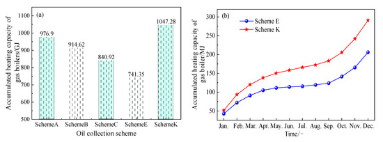
Figure 8.
(a) Accumulated heating capacity of gas boilers under different oil recovery schemes (annual total); (b) changes in cumulative heating capacity (annual total) of gas boilers over time.
Figure 9 shows the cumulative heating capacity of the gas boilers in Scheme E and Scheme K during different months. Observing the images, it was found that the distribution pattern of heat supply is lower in summer and higher in winter, which is inversely correlated with seasonal temperature. Calculating the reduction rate of heating supply in Scheme E compared to Scheme K results in obtaining the change curve of the reduction rate in the graph. Observing the image, it is found that the gas heating demand in Scheme E in June and July is only about 8 GJ, which can be reduced by 71.7–68.9% compared to Scheme K. Gas boiler heating is directly related to the use of natural gas energy, and reasonable selection of the oil collection scheme is of great significance for saving primary energy.
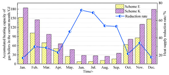
Figure 9.
Cumulative heating capacity of gas boilers in different months for Scheme E and Scheme K.
Figure 10a shows the total annual storage/release heat of the phase-change heat storage tank during the implementation of the five oil recovery schemes. Due to the fact that the heat stored in the phase-change heat storage tank comes from the heat collected by the collector, the heat storage capacity of the five schemes is proportional to the total heat collected by the solar collector. The maximum annual cumulative heat storage capacity of the phase-change heat storage tank in scheme E is 383.23 GJ, which is 24.2% (74.65 GJ), 8.9% (30.63 GJ), 0.4% (1.39 GJ), and 52.9% (132.66 GJ) higher than those of Schemes A, B, C, and K. The phase-change heat storage tank heats the heat-transfer fluid by releasing heat, thereby utilizing the stored heat. The maximum annual cumulative heat release of the phase-change heat storage tank in Scheme E is 346.16 GJ, which is 27.2% (74.04 GJ), 9.7% (30.58 GJ), 0.5% (1.57 GJ), and 61.3% (131.58 GJ) higher than those of Scheme A, B, C, and K. Figure 10b shows the heat storage and release efficiency of the phase-change heat storage tank, which is determined by the ratio of heat release to heat storage capacity. The calculation revealed that the heat storage and release efficiency of the phase-change heat storage tank in Scheme E was as high as 90.33%, indicating that its energy utilization efficiency was the highest and the heat loss rate was the lowest.
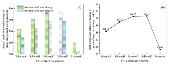
Figure 10.
(a) Accumulated heat storage/release (annual total) and (b) heat storage and release efficiency of phase-change heat storage tank with different oil recovery schemes.
As shown in Figure 11, the proportion of the solar collector, the gas boiler, and the phase-change heat storage tank used for heating and maintaining the temperature of the settling tanks during the implementation of the five oil harvesting schemes is the average annual heat supply. The direct heating capacity of the solar collector used for the settling tank is obtained by subtracting the part used for the phase-change heat storage from the total heat collection. The sum of the solar collectors and phase-change heat storage boxes in Scheme E accounts for 53.03% of the total heat supply, which exceeds the proportion of the gas boiler heat supply, whereas the proportion of the gas heat supply in the other schemes exceeds 50%. This proves that Scheme E has a lower gas consumption in the combined heating system during operation and has better energy-saving and environmental protection benefits.
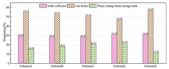
Figure 11.
Annual heating volume proportion of the solar collector, the gas boiler, and the phase-change heat storage tank.
3.2. Analysis of Long Cycle System Operation Characteristics
As shown in Figure 12, the variation in the solar energy guarantee rate of the optimized settling tank solar–gas combined heating system during one year of operation shows an overall trend of first increasing and then decreasing with the increase in the operating time, and the maximum solar energy guarantee rate (about 62.7%) is achieved in September and October. Due to the initial design of the system, the solar energy guarantee rate is less than 40% during the period from January to April, indicating a low contribution rate of solar energy during this period and a low proportion of the system’s thermal load. Since June, due to factors such as increased environmental temperature and weakened initial impact, the solar energy guarantee rate has remained above 50%, thereby proving the reliability of solar heating.
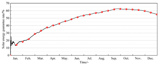
Figure 12.
Solar energy guarantee rate(The time interval corresponding to the red balls is half a month).
Figure 13 shows the average temperature of the original oil layer of the settling tank during the one-year operation of the solar–gas combined heating system. During the annual operation period, the average temperature of crude oil is maintained above 39 °C, meeting the working requirements of the settling tank. During the period from late March to early October, the temperature of crude oil sometimes reaches around 43 °C. This is because the environmental temperature is high during this period, the heat dissipation capacity of the settling tank is low, and the heat load is small. On the other hand, the heat collector collects more heat, and the heat-transfer fluid temperature is high, which is not absorbed in a timely manner by the phase-change heat storage tank, resulting in a higher crude oil temperature.
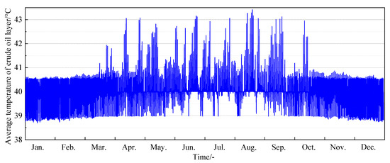
Figure 13.
Monthly variation in the average temperature of the original oil layer in the settling tank.
Figure 14 and Figure 15 show the monthly variation curves of the average temperature and PCM solid–liquid ratio of the phase-change heat storage tank during the one-year operation of the settling tank solar–gas combined heating system. As shown in the figure, the average temperature of the phase-change heat storage tank fluctuates around 50–58 °C during January, February, and November and December, indicating that the temperature of the phase-change heat storage tank is lower than the PCM phase-change temperature during this period. From March to October, due to the increase in environmental temperature and enhanced solar radiation, the PCM in the phase-change heat storage tank is heated by a high-temperature heat-transfer fluid until it completely melts, and its average temperature is higher than the phase-change temperature, with a maximum of about 95 °C. The phase-change heat storage tank can utilize PCM sensible heat for system energy absorption during the cold months of spring and winter. From March to October, the latent heat of phase change can be utilized. According to the calculations, approximately 65% of the year-round, the latent heat of PCM melting can be utilized, fully leveraging the heat storage and release advantages of phase-change materials.
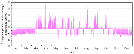
Figure 14.
Monthly variation in average temperature in the phase-change heat storage tank.
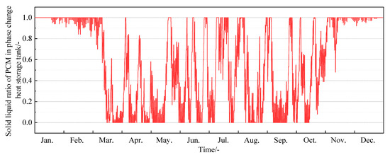
Figure 15.
Monthly variation of solid–liquid ratio in PCM phase-change heat storage tank.
3.3. Analysis of Short Cycle System Operation Characteristics
To analyze the detailed operating parameters of the system during operation, we randomly selected the operating data of each component from the first week of spring (i.e., 1 March to 7 March, a total of seven days). Figure 16 shows the average temperature of the original oil layer and the operating parameters of the oil recovery control signal. As previously mentioned, when the oil collection control signal is 1, the settling tank begins a new cycle of oil collection and liquid inlet, and the average temperature of the crude oil layer returns to a liquid inlet temperature of 40 °C. When the control signal is 0, the heat-tracing coil of the settling tank starts heating, and the settling tank enters a temperature maintenance state, with a total of two complete cycles per day.
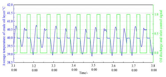
Figure 16.
Average temperature of crude oil layer and operating parameter diagram of oil recovery control signal.
Figure 17 shows the operating parameters of the solar collector and phase-change heat storage tank. When the solar collector is shut down, its outlet heat-transfer fluid temperature is the same as that of the environment. At point A, the collector meets the opening time conditions, and its outlet heat-transfer fluid is heated. However, at this point, the temperature of the heat-transfer fluid at the collector outlet is relatively low, which does not meet the conditions for heating the settling tank. Until point C, when the temperature difference between the heat-transfer fluid at the collector outlet and the crude oil meets the set requirements, the collector starts heating, and the temperature of the original oil layer in the settling tank gradually increases. At point B, the solar collector closes.
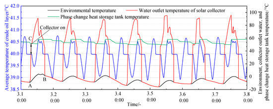
Figure 17.
Operating parameter diagram of solar collector and phase-change heat storage tank.
Figure 18 shows the operating parameters of the solar collectors and gas boiler. During the day, the system is mainly heated by a solar collector for heat transfer fluid heating, and at night, when the collector is closed, it is heated by a gas boiler. Due to the shared outlet circuit between the solar collectors and gas boilers, when the fluid temperature at the collector outlet meets the temperature maintenance requirements of crude oil, the outlet temperature curve of the gas boiler coincides with the outlet temperature curve of the collector. When the solar radiation is insufficient on cloudy and rainy days, as shown by the data in the black circles in the figure, the maximum total radiation on the inclined surface on that day is less than 2300 kJ/(h·m2), and it is difficult to meet the system’s heat load demand solely by relying on the collector. At this time, the gas boiler performs auxiliary heating and secondary heating, and the heat-transfer fluid temperature is heated from 88 °C at the collector outlet to 95 °C to supplement the heat required for the settling tank.
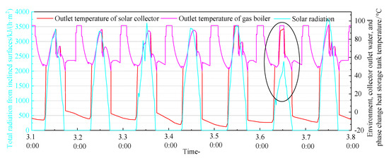
Figure 18.
Operating parameter diagram of solar collector and gas boiler.
3.4. Comprehensive Benefit Analysis
The initial investment of the solar–gas combined heating system of the settling tank is mainly composed of the improvement investment of the settling tank and the system equipment investment. The prices of the materials and equipment involved are shown in Table 7.
Table 7.
Prices of materials and equipment.
- 1.
- Annual energy saving of the settling tank solar–gas combined heating system [31] is calculated as follows:where Jn is the total annual solar radiation on the inclined surface of the collector, MJ/m2.
According to the statistics, the total annual solar radiation is 5780 MJ/m2 in the local area, and the thermal efficiency of the solar collector is 40%. The annual energy saving of the solar–gas combined heating system of the settling tank is calculated as 727,988.69 MJ.
- 2.
- Total energy-saving cost of solar–gas combined heating system of the settling tank during the total life SAV [31]:where P is the discount coefficient considering bank interest rate and fuel price fluctuation comprehensively; CC is the heating price of conventional energy, CNY/MJ; Sin is the total additional investment in the system, CNY; Da is the percentage of the total additional investment spent annually on system maintenance. Among them, P can be calculated as follows:where d is the annual market discount rate, which can be calculated as the bank loan interest rate; e is the annual fuel price increase rate; n is the calculation period.
The total additional investment of the system is CNY 666,670, and the annual system maintenance cost is 1% of the total additional investment. The market discount rate is 2%, the annual fuel increase rate meter is 1%, the discount coefficient P is CNY 13.74 after 15 years of system operation, and the total energy-saving cost is CNY 397,007 during the total life of the system.
- 3.
- Dynamic payback period of solar–gas combined heating system for the settling tank TY (year) [31]:
The number of years during the life period when the total energy-saving cost and total additional investment of the system reach the break-even balance is the dynamic payback period of the system. The calculated discount coefficient P’ is CNY 8.61, and the payback period of the system investment is 9.14 years.
- 4.
- CO2 emission reduction in the settling tank solar–gas combined heating system during the total life [31]:where n is the system life, which is calculated as 15 years; W is the calorific value of standard coal, which is 29.308 MJ/kg; Em is the efficiency of a conventional energy water-heating device; FCO2 is a carbon emission factor.
The total CO2 emission reduction during the lifetime of the system is 788,291.3 kg.
4. Conclusions
To address the challenges posed by the high consumption of oil and gas resources, low energy efficiency, and environmental pollution associated with traditional heating methods for oilfield setting tanks, a novel approach called the combined solar and gas heating system for setting tanks has been proposed. The equipment selection was carried out according to the system design requirements, and the basic parameters of the simulation calculation of the solar–gas combined heating system of the settling tank were obtained. Finally, a simulation model of the settling tank solar–gas combined heating system was established, and the energy consumption characteristics of the system under different control strategies and the annual operation characteristics of the optimized system were compared and analyzed. The system benefits, such as the annual energy saving, total energy-saving cost, payback period of investment, and CO2 emission reduction, were evaluated. The main conclusions are as follows:
- The optimal solution for the oil-collection period of the settling tank is E (4:00–8:00). This solution results in the highest annual cumulative heat collection by the collector, the lowest annual total heat supply by the gas boiler, and the highest heat storage and release efficiency of the phase-change heat storage tank. Compared to the most adverse plan K (10:00–14:00), the annual cumulative heat collection of the collector can be increased by 6.7% (56.91 GJ), the annual total heat supply of the gas boiler can be reduced by 29.2% (305.93 GJ), and the heat storage and release efficiency of the phase-change heat storage tank can be improved by 4.69%.
- The average crude oil temperature is maintained above 39 °C throughout the year, thereby meeting the requirements of the settling tanks. The solar–gas combined heating system of the settling tank achieves the highest solar guarantee rate (about 62.7%) in September and October Approximately 65% of the year, the latent heat of PCM melting can be effectively utilized, fully leveraging the advantages of the heat storage and release advantages of phase-change materials.
- The service life of the settling tank solar–gas combined heating system is calculated as 15 years, and its annual energy saving, total energy-saving cost, dynamic payback period, and CO2 emission reduction are 727,988.69 MJ, CNY 397,007, 9.14 years, and 753,069.8 kg, respectively.
Author Contributions
Conceptualization, Y.W., D.L., Z.W. and X.Z.; Methodology, F.M. and L.M.; Software, Y.Y.; Validation, Y.W.; Investigation, F.M.; Data curation, Y.Y.; Writing—original draft, F.M. All authors have read and agreed to the published version of the manuscript.
Funding
This work was supported by the National Science Foundation of China (NSFC) (No. 52078110, 52074090); the Science Foundation of Heilongjiang Province (No. LH2019E015); the Scientific Project of Ministry of Housing and Urban-Rural Development of China (No. 2020-K-184 and 2020-K-162), and the Science and Technology Plan Project of Daqing City (No. zd-2021-50).
Institutional Review Board Statement
Not applicable.
Informed Consent Statement
Not applicable.
Data Availability Statement
The data that support the findings of this study are available upon reasonable request from the corresponding authors.
Conflicts of Interest
The author declares no conflict of interest.
References
- Ding, P.; Dang, W.; Wang, L.; Liu, J. Current Status and Prospects of Oilfield Produced Water Reinjection Treatment Technology. Mod. Chem. Ind. 2019, 39, 21–25. [Google Scholar]
- Bao, Z. Methods for Improving the Quality of Oil and Water Treatment in Joint Stations. China Pet. Chem. Stand. Qual. 2022, 42, 25–27. [Google Scholar]
- Wang, X. Research on Heat Transfer Characteristics and Structural Stress Influencing Factors of Heat Tracing Coils in Sewage Settlement Tanks. Ph.D. Thesis, Northeast Petroleum University, Daqing, China, 2022. [Google Scholar]
- Liu, X.; Chen, D.; Zhang, W.; Qin, W.; Zhou, W.; Qiu, T.; Zhu, B. An assessment of the energy-saving potential in China’s petroleum refining industry from a technical perspective. Energy 2013, 59, 38–49. [Google Scholar] [CrossRef]
- Zou, C.; He, D.; Jia, C.; Xiong, B.; Zhao, Q.; Pan, S. Connotation and pathway of world energy transition and its significance for carbon neutral. Acta Pet. Sin. 2021, 42, 233–247. [Google Scholar]
- Helman, C. Oil From The Sun. Forbes 2011, 187, 86–89. [Google Scholar]
- BrightSource Energy Delivers World’s Largest Solar-to-Steam Facility for Enhanced Oil Recovery to Chevron. [EB/OL]. Available online: http://www.businesswire.com/news/home/20111003006187/en/BrightSourceEnergyDelivers-World%E2%80%99s-Largest-Solarto-Steam-Facility (accessed on 1 March 2023).
- Moritis, G. Chevron starts California demo of solar-to-steam enhanced recovery. Oil Gas J. 2011, 109, 87–88. [Google Scholar]
- Yao, Z. Research on the Technology of Using Concentrated Solar Energy to Generate Steam Injection for Oil Production. Energy Conserv. Emiss. Reduct. Pet. Petrochem. Ind. 2013, 3, 1–6. [Google Scholar]
- Bierman, B.; Treynor, C.; O’donnell, J.; Lawrence, M.; Chandra, M.; Farver, A.; Von Behrens, P.; Lindsay, W. Performance of an enclosed trough EOR system in South Oman. Energy Procedia 2014, 49, 1269–1278. [Google Scholar] [CrossRef]
- Luo, W.; Zhao, R.; Xia, X.; Yao, T.; Xiao, A. Feasibility Analysis of the Application of Solar Energy Closed Cell Heavy Oil Thermal Recovery Technology in Xinjiang Oilfield. J. Xi’an Pet. Univ. (Nat. Sci. Ed.) 2015, 30, 64–68. [Google Scholar]
- Du, M.; Jing, Q.; Zhang, Z.; Li, J.; Yin, R. Key Technologies for Heavy Oil Thermal Recovery through Solar Photothermal Conversion. Energy Storage Sci. Technol. 2020, 9, 62–69. [Google Scholar]
- Qian, J.; Wang, Q. Development on solar—Assisted sewage source heat pump system for crude oil heating. J. Harbin Univ. Commer. (Nat. Sci. Ed.) 2017, 33, 477–481. [Google Scholar]
- Li, W.; Wu, Y.; Hu, J.; Zhao, X. Application of solar photovoltaic integration technology in crude oil heating system. Energy Conserv. Pet. Petrochem. Ind. 2021, 11, 13–16. [Google Scholar]
- Pei, J.; Chen, G. Application of solar energy and heat pump technology in crude oil heating systems. Oil Gas Storage Transp. 2012, 31, 289–291. [Google Scholar]
- Xu, X.; Xiao, Y.; Xu, Y. On site application of crude oil heating energy-saving technology in Ansai Oilfield. Petrochem. Equip. 2019, 48, 69–72. [Google Scholar]
- Hao, Y.; Lv, S.; Li, H. Research on the Application of Solar Photovoltaic Photothermal Systems in Crude Oil Gathering and Transportation. Pet. Petrochem. Green Low Carbon 2020, 5, 69–72+77. [Google Scholar]
- Mammadov, F.; Samadova, U.; Salamov, O. Experimental results of using a parabolic trough solar collector for thermal treatment of crude oil. J. Energy South. Afr. 2008, 19, 70–76. [Google Scholar] [CrossRef]
- Lasich, J.; Kaila, N. Helitherm-solar power throughput enhancement and heat tracing for heavy oil pipelines. In SPE International Thermal Operations and Heavy Oil Symposium; SPE: New Orleans, LA, USA, 2001. [Google Scholar]
- Wang, X.; Ye, C. Energy saving application of solar photothermal technology in oil and gas fields. Pet. Petrochem. Energy Conserv. 2013, 3, 22–25. [Google Scholar]
- Hou, L.; Zhang, X.; Zhou, W. The application of solar energy in surface engineering of oil and gas fields. Appl. Energy Technol. 2011, 1, 40–43. [Google Scholar]
- He, Z. Application of solar heating system for raw petroleum during its piping transport. Energy Procedia 2014, 48, 1173–1180. [Google Scholar] [CrossRef]
- Fu, Z.; Gao, H.; Zhang, T.; Zhu, Z. Calculation of Heat Load Matching for Solar Heating Crude Oil Storage and Transportation System. Oil Gas Storage Transp. 2019, 38, 1306–1310. [Google Scholar]
- Ai, L. Research on the area calculation of collectors and heat exchange coils in oil storage tanks using solar indirect heating systems. Sol. Energy 2012, 16, 56–58. [Google Scholar]
- Li, S.; Lin, W.; Gong, X.; Sun, Y.; Ma, Z. Corrugated transpired solar collectors: Mathematical modeling, experimental investigation, and performance analysis. Sol. Energy 2023, 262, 111839. [Google Scholar]
- Al-Rabeeah, A.Y.; Seres, I.; Farkas, I. Experimental investigation of parabolic trough solar collector thermal efficiency enhanced with different absorber coatings. Int. J. Thermofluids 2023, 19, 100386. [Google Scholar]
- Zhao, J.; Dong, H.; Fu, X.; Lei, Q. Cooling gelation behavior of waxy crude oil in floating roof tanks during static storage. J. Chem. Eng. 2017, 68, 4882–4891. [Google Scholar]
- Li, D.; Wu, Y.; Liu, C.; Yang, R.; Arıcı, M. Thermal Analysis of Crude Oil in Floating Roof Tank Equipped with Horizontal Heating Finned Tube Bundles. ES Energy Environ. 2021, 13, 65–76. [Google Scholar]
- GB 50495-2019; Solar Heating Engineering Technical Standard. China Architecture Publishing House: Beijing, China, 2019.
- GB 50364-2018; Civil Building Solar Water Heating System Application Technical Standard. China Architecture Publishing House: Beijing, China, 2018.
- Zheng, R. Engineering Technical Manual of Solar Water Heating System for Civil Buildings; Chemical Industry Press: Beijing, China, 2011. [Google Scholar]


Disclaimer/Publisher’s Note: The statements, opinions and data contained in all publications are solely those of the individual author(s) and contributor(s) and not of MDPI and/or the editor(s). MDPI and/or the editor(s) disclaim responsibility for any injury to people or property resulting from any ideas, methods, instructions or products referred to in the content. |
© 2023 by the authors. Licensee MDPI, Basel, Switzerland. This article is an open access article distributed under the terms and conditions of the Creative Commons Attribution (CC BY) license (https://creativecommons.org/licenses/by/4.0/).