Review

Microscopic Flow of CO2 in Complex Pore Structures: A Recent 10-Year Review

1
School of Mechanics and Engineering, Liaoning Technical University, Fuxin 123000, China
2
State Key Laboratory of Geomechanics and Geotechnical Engineering, Institute of Rock and Soil Mechanics, Chinese Academy of Sciences, Wuhan 430071, China
3
Shenyang Research Institute, China Coal Technology & Engineering Group Corp, Shenyang 113122, China
4
State Key Laboratory of Coal Mine Safety Technology, Shenyang 113122, China
*
Author to whom correspondence should be addressed.
Sustainability 2023, 15(17), 12959; https://doi.org/10.3390/su151712959
Submission received: 18 July 2023 / Revised: 13 August 2023 / Accepted: 24 August 2023 / Published: 28 August 2023

Abstract

:
To prevent CO2 leakage and ensure the safety of long-term CO2 storage, it is essential to investigate the flow mechanism of CO2 in complex pore structures at the pore scale. This study focused on reviewing the experimental, theoretical, and numerical simulation studies on the microscopic flow of CO2 in complex pore structures during the last decade. For example, advanced imaging techniques, such as X-ray computed tomography (CT) and nuclear magnetic resonance (NMR), have been used to reconstruct the complex pore structures of rocks. Mathematical methods, such as Darcy’s law, the Young–Laplace law, and the Navier-Stokes equation, have been used to describe the microscopic flow of CO2. Numerical methods, such as the lattice Boltzmann method (LBM) and pore network (PN) model, have been used for numerical simulations. The application of these experimental and theoretical models and numerical simulation studies is discussed, considering the effect of complex pore structures. Finally, future research is suggested to focus on the following. (1) Conducting real-time CT scanning experiments of CO2 displacement combined with the developed real-time CT scanning clamping device to achieve real-time visualization and provide a quantitative description of the flow behavior of CO2 in complex pore structures. (2) The effect of pore structures changes on the CO2 flow mechanism caused by the chemical reaction between CO2 and the pore surface, i.e., the flow theory of CO2 considering wettability and damage theory in a complex pore structures. (3) The flow mechanism of multi-phase CO2 in complex pore structures. (4) The flow mechanism of CO2 in pore structures at multiscale and the scale upgrade from microscopic to mesoscopic to macroscopic. Generally, this study focused on reviewing the research progress of CO2 flow mechanisms in complex pore structures at the pore scale and provides an overview of the potential advanced developments for enhancing the current understanding of CO2 microscopic flow mechanisms.

1. Introduction

Due to the increasing greenhouse effect as well as acute global climate and environmental problems, countries worldwide have reached a consensus to actively respond to climate change and reduce greenhouse gas emissions [1,2]. Since industrialization has continued since the industrial revolution, the use of fossil fuels has increased, and large amounts of CO2 gas have been directly discharged into the air, which is one of the main reasons for the intensification of the greenhouse effect [3]. CO2 emissions have led to a series of environmental problems, such as drought, glacier melt, and sea level rise, which have caused incalculable harm to the environment on which human beings depend [4]. At present, many technologies are available to control CO2 emissions, such as improving the efficiency of fossil energy combustion, the efficient development and utilization of green and clean energy, and carbon capture and storage (CCS) [5]. CCS refers to the use of separation and purification technology to collect a large amount of CO2 from industrial waste gas and inject it into appropriate underground reservoirs for permanent storage [6], which is recognized as one of the effective methods to manage CO2 [7]. At present, the membranes used for the selective transport of CO2 in the mixture of gases based on hollow alumina fiber-supported silica have been developed [8]. The application of this advanced technology greatly improves the efficiency of CO2 capture. The main geological layers used for storage include abandoned mines, unrecoverable coal seams, depleted oil and gas fields, deep saline aquifers, and the ocean [9]. The storage depth is generally below 800 m. CO2 geological storage is the most important part of CCS, and the storage capacity and safety of geological storage bodies determine the effectiveness of CO2 emission control [10]. Compared to other gases, CO2 is affected by temperature and pressure in the reservoir, and will produce phase transitions (gaseous, liquid, and supercritical). The microscopic flow of different phase states of CO2 in porous media is different. In addition, when CO2 flows in a reservoir, it can undergo physical and chemical reactions with reservoir water and matrix, causing damage to the reservoir. Meanwhile, the complexity, heterogeneity, and wettability [11] of the pores directly affect the flow behavior of CO2 in reservoirs. Therefore, investigating the CO2 flow law and revealing the CO2 microscopic flow mechanism are key for evaluating the storage capacity and safety of geological storage bodies.
Numerous studies have been conducted on the flow of CO2 in geological storage bodies. Lassen et al. [12] injected gaseous CO2 into heterogeneous porous media at different rates, and the flow of CO2 was monitored by sensors. The results showed that large-scale heterogeneity controlled the overall migration of gaseous CO2 in porous media, whereas a smaller scale was important for gas saturation. The higher the injection rate, the larger the transverse diffusion of the gas phase. Zhang et al. [13] proposed that Darcy’s law could be used to describe a two-phase fluid flow in porous media at the macroscopic scale. Saleem et al. [14] compared and verified the constructed two-phase flow model using field observation data, such as the CO2 eruption time, changes in the sediment pH, gas leakage rate, flow process, fluid interaction, and CO2 dissolution in the CO2 plume. The results showed that the CO2 plume was formed and developed at a stable rate during the flow process, and the dissolution rate increased with an increase in the injection rate. These studies elucidated the flow of CO2 from a macroscopic perspective. However, the flow behavior of CO2 in a storage body is easily affected by its complex pore structures. In macroscale research, the complex pore structures of the storage body have not been accurately characterized. The research results were also based on macroscale flow and often ignored the effect of the pore structure complexity. Therefore, an accurate description of the microscopic flow of CO2 is crucial for determining storage capacity and long-term safety [15].
X-ray computed tomography (CT) and nuclear magnetic resonance (NMR), as non-invasive ad non-destructive advanced imaging technologies [16], are advantageous for reconstructing the complex pore structures of cores [17] and obtaining the key parameters, such as the porosity, permeability, contact angle, and capillary number. The visualization and quantitative characterization of the complex pore structures at the microscopic scale can be realized [5]. Berg and Dalton et al. [18,19] obtained accurate complex pore structures of sandstone and investigated the effects of the permeability and wettability on the CO2 flow behavior. Liu et al. [20,21] first used a new reconstruction method to establish the fracture-controlled matrix unit then used the CT scanning technique to obtain the relevant parameters of the proposed fracture control matrix unit mass transfer model. The correctness of the model was verified by a comparison with the experimental results of the microscopic spontaneous imbibition. Liu et al. [22,23] studied the dynamic production process of a fractured reservoir and the influence of a complex pore structure on the imbibition recovery based on a fracture-controlled matrix unit. Liu et al. [24] performed microscopic spontaneous imbibition experiments, CT scans, and NMR tests on two mixed wetted core samples. The impact of mixed wettability on the micro-spontaneous imbibition at the pore scale was investigated. The results showed that an effective imbibition was produced so long as water-wet walls were present in the mixed wettability pores. Furthermore, a core-scale mixed wettability model was established by Liu et al. [25] and, based on the phase-field theory, the influence of wettability on the oil–water two-phase imbibition was studied. In addition, Liu and Song et al. [26,27] proposed two new modeling methods based on CT scanning: the finite volume element modeling method (Figure 1a) and the pore network model based on the maximum sphere algorithm (Figure 1b). The feasibility of the model was verified. The parameters of the models constructed using two different modeling methods are shown in Table 1 and Table 2, respectively.
In addition, experts conducted several theoretical and numerical simulations on the flow mechanism of CO2 at the macroscale. Krause et al. [28] performed a numerical simulation study of the CO2–brine two-phase flow using the modified Carman–Kozeny equation. The distribution of CO2–brine in the core was predicted. Theoretical studies and numerical simulations at the macroscale play a crucial role in revealing the flow mechanism of CO2. However, the complex pore structures have a considerable effect on the CO2 microscopic flow. The lack of mathematical and numerical models that consider the influence of the pore structure complexity may lead to bias in the conclusions.
The previous studies predominantly focused on the macroscopic flow of CO2 in porous media, often overlooking the microscopic flow mechanisms. Simultaneously, the research processes frequently oversimplified the pore structures and neglected the influence of their complexity on the microscopic flow of CO2. At present, there is a lack of comprehensive reviews on the microscopic flow of CO2 in complex pore structures. In order to fill the knowledge gap in this field, it was necessary to conduct detailed academic research and summary. Therefore, we collated and analyzed relevant literature on the microscopic flow of CO2. In particular, the complex pore structures substantially affected the CO2 microscopic flow mechanism. At present, experimental methods, theoretical analyses, and numerical simulations are advanced, owing to the pore structure complexity of geological storage bodies, which is difficult to accurately express in physical model reconstruction, mathematical model characterization, and numerical model construction. Therefore, it is challenging to clearly reveal the microscopic flow mechanism of CO2 in a complex pore structure. To solve this problem, this study systematically reviewed the recent advances in the microscopic flow of CO2 in complex pore structures in the last decade to provide some technical and theoretical support for CO2 geological storage. Overall, this review article focused on the effects of complex pore structures on the microscopic flow behavior of CO2 through three aspects: experimental studies, theoretical studies, and numerical simulations. It aimed to enhance the current understanding of the CO2 microscopic flow mechanism to help beginners quickly obtain an in-depth understanding of the current state of research in this field. Finally, the potential challenges and new research directions for future work were identified and elucidated.

2. Flow Experiments of CO2 in Complex Pore Structures

Numerous experiments have been conducted to study the microscopic flow of CO2 in pore structures, and fruitful results have been achieved. This section introduces the research progress of the microscopic flow mechanism of CO2 from four different aspects through an analysis of the relevant literature.

2.1. Traditional Characterization of Pore Structures during CO2 Microscopic Flow

Mercury intrusion porosimetry (MIP) [29], scanning electron microscopy (SEM) [30], and gas adsorption [31] have been used to characterize the pore structures of the storage body and further explore the flow of CO2. Du et al. [32] used high-pressure mercury intrusion and permeation experiments to investigate the effect of CO2 injected into coal. The results showed that the reaction between CO2–water and coal led to an increase in the pore space and greatly increased the permeability, which increased the permeability area of CO2 and improved the CO2 storage capacity. Using SEM, Khather et al. [33] observed that a decrease in the pH during CO2 injection caused the dissolution and migration of minerals, which resulted in an increase in the rock permeability and flow capacity of CO2. Pearce et al. [34] studied the physical properties of the reservoir after CO2 injection using SEM and found that the movement of fine particles could result in opening or blocking the pores during CO2 injection, increasing or decreasing the permeability and affecting the CO2 injection capacity. Brattekas and Haugen [35] used high-resolution micro-positron emission tomography (micro-PET) and radiotracers to achieve CO2 tracing during the flow and capillary capture. The results showed that CO2 mainly flowed into the outer part of the core with a high permeability.
However, these techniques had numerous limitations for accurately characterizing the pore structure complexity in rocks. For example, MIP only obtained the total porosity of the sample and did not characterize the complexity of the pore distribution within the sample. SEM was an effective technique for generating 2D images of the microstructures. However, it did not provide 3D images, which were important for evaluating the pore structure complexity [5]. The measurement results obtained using gaseous adsorption methods were often constrained by the limited pore-scale range, and accurately characterizing the complexity of pore structures became challenging due to the size and interactions of the gas molecules [36]. More importantly, the traditional characterization methods did not visualize and quantitatively describe the microscopic flow of CO2. In addition, Tang et al. [37] conducted a comprehensive comparison of the rock pore structure characterization techniques, including experimental analyses, image analyses, and digital core techniques, and emphasized the importance of digital core techniques for solving complex pore structure characterization. Therefore, to accurately reconstruct the 3D complex pore structures and visually and quantitatively study the microscopic flow mechanism of CO2 in the geological storage body, it was necessary to use advanced techniques, such as CT scanning and NMR, to conduct an in-depth analysis using multidisciplinary intersection research ideas.
It is worth noting that with the continuous improvement of artificial intelligence (AI), some research applied it in the field for studying the microscopic flow of CO2 and achieved some remarkable results. A hybrid artificial intelligence model integrating a back propagation neural network (BPNN), genetic algorithm (GA), and adaptive boosting algorithm (AdaBoost) was proposed by Yan et al. [38], which was used to evaluate the change in the coal strength caused by the interaction between CO2 and coal in the flow process. Zhang et al. [39] proposed four advanced machine learning schemes, including RBFNN-MVO, RBFNN-GWO, RBFNN-PSO, and MLPLM, to evaluate the contact angle of various shale systems. Overall, AI plays a key role in predicting the parameters of complex pore structures as well as evaluating safety. In addition, the method of using AI to predict fluid flow is a hot topic for future research.

2.2. Effects of the Porosity and Permeability Characteristics on the Microscopic Flow Mechanism of CO2

The influence of the key parameters, including the porosity and permeability, on CO2 flow in geological storage bodies is very important. By simulating 2D fluid flow experiments, Kitamura et al. [40] found that the flow behavior of CO2 was strongly influenced by the small-scale heterogeneity of the pore structures. However, the simulation results had some errors since the model was 2D and could not fully describe the pore structure complexity. To investigate the effect of the reservoir laminar structures on the flow behavior of CO2, Krishnamuthy et al. [41] used the CT scanning technique to observe the flow path of CO2 by measuring the CO2 saturation variation in the rock. The results showed that CO2 preferentially flowed through the region with a larger porosity and passed unevenly along the axial direction (Figure 2). However, seepage under in situ conditions was not considered. Thus, the pore distribution in reservoir cores under in situ conditions could not be obtained. To accurately study the CO2 microcosmic flow, Wang et al. [42] injected liquid CO2 into a brine-saturated core. Multiscale CT scanning of sandstone was conducted and the distribution of the porosity at different locations in the core under in situ flow conditions was obtained. The phenomenon of CO2 preferentially passing through the locations with a higher porosity was observed from the images. Al-Bayati et al. [43] conducted a displacement experiment on the stratified core samples using the CT scanning technique. Figure 3 shows the 2D images of the fluid distribution in the XY direction of the stratified samples before and after CO2 displacement. As illustrated in the Figure 3, CO2 first bypassed the low-permeability layer, leaving a considerable amount of oil to preferentially enter the high-permeability layer. Owing to the occurrence of the cross-flow phenomenon, CO2 was transferred from the high- to the low-permeability layer.
A clay interlayer, one of the typical representatives of a low-permeability layer, had an important influence on the CO2 flow. Using CT scanning, Xu et al. [44] studied the flow characteristics of CO2 in a special sandstone containing multiple thin clay interlayers. The experiment demonstrated that the flow channel of CO2 was mainly established in the sandstone, and the clay interlayer hindered the CO2 flow. However, the description of how the CO2 flow was hindered by the clay interlayer was too vague. Therefore, Xu et al. [45] further monitored the flow process of CO2 in the interior of the clay interlayer sample (Figure 4). When the injection direction was parallel to that of the clay interlayer, the clay interlayer separated the CO2 flow (Figure 4a). When the injection direction was perpendicular to that of the clay interlayer, the clay interlayer hindered the forward CO2 flow (Figure 4b).

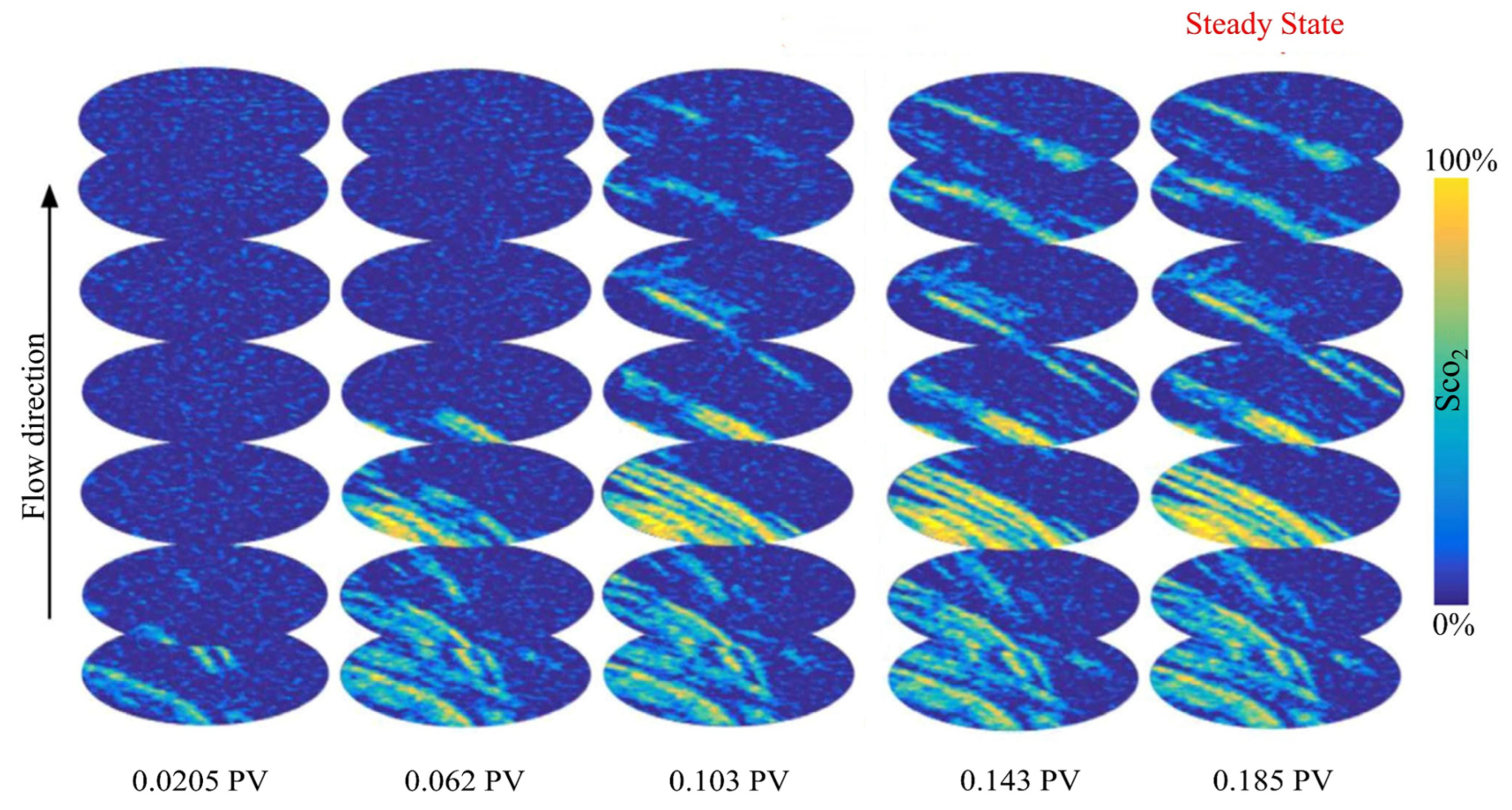
2.3. Two-Phase Flow Law in CO2 Microscopic Flow

When CO2 was injected into the deep brine layer, it entered the reservoir pore structures to displace the original fluid from the pore space, and the flow process was an immiscible two-phase flow [16]. However, it was difficult to observe the space–time variation of the two-phase interface between the immiscible two-phase fluids in the porous media. Therefore, the immiscible two-phase flow needed to be understood from a pore-scale perspective, which was very important and extremely complex [46].
Using the CT scanning technique, Kogure et al. [47] injected CO2 into the Berea sandstone at different times in opposite directions, and the flow behavior of CO2 in the Berea sandstone was observed. The images showed several narrow pore throats that allowed for the CO2 flow. Despite injections from opposite directions, the distribution of CO2 was essentially the same in the final stage of injection (Figure 5). Liu et al. [48] injected CO2 into a glass bead bed in both the upward and downward directions, and a displacement-saturated water experiment was conducted to investigate the distribution of CO2 in the core. As shown in Figure 6, the displacement effect of CO2 injected downward was substantially better than that of CO2 injected upwards (Figure 6b). This was attributed to the “gas channeling” phenomenon when CO2 was injected upward, but the cause of the “gas channeling” phenomenon was not discussed in depth. Lv et al. [49] combined the CT scanning technique and a micromodel to study the flow process of CO2–brine in the pore structures at different injection rates under static and transient conditions. The results showed that a higher injection rate caused a higher displacement efficiency but a lower sweep efficiency. Further, using the NMR technique, Teng et al. [50] found that the different viscosities and densities of CO2 and water caused the “gas channeling” phenomenon of CO2, which led to the premature breakthrough of CO2 and reduced the displacement efficiency. In addition, Zhang et al. [13] obtained the local porosity and saturation of the Berea sandstone. The results showed that the forward movement of CO2 on the capillary pressure was the main reason for the formation of the pathway of the CO2 flow. CO2 preferentially passed through the large-sized pores, and the seepage zone gradually expanded whereas the CO2 saturation increased.
The Influence of pore geometry on the microscopic flow mechanism of CO2 was not ignored. Zhang et al. [51] used CT scanning to scan the displacement process of CO2 and found that CO2 was unevenly distributed in the sandstone samples. A larger flow patch was formed during the flow process. Herring et al. [52] adopted the Bentheimer sandstone core and used the CT scanning technique to observe the displacement process of CO2 at the pore scale. The images showed that CO2 invaded the pore space in a capillary fingering regime (Figure 7). Liu et al. [53] visualized and quantitatively analyzed the dynamic diffusion process of CO2 in n-decane-saturated porous media. The results showed that the channels of the porous media hindered the diffusion of CO2. The local diffusion coefficient of CO2 gradually decreased with time along the diffusion path until it reached a steady state.
Figure 5. X-ray CT images of the distribution of scCO2 in the Berea sandstone [47].
Sustainability 15 12959 g005
Figure 6. Characterization of the displacement process and complex pore structures based on CT scanning: (a) 3D images of the CO2 distribution in the displacement process and the analysis of the displacement efficiency [48]; (b) 3D and 2D images of the complex pore structures and grayscale 2D images of the pores [52], * Indicates that capillary pressure is estimated for this data point.
Sustainability 15 12959 g006

2.4. Microscopic Flow of CO2 in Different Phase States

In geological storage, appropriate CO2 phase states, including gaseous, liquid, and supercritical, should be selected according to the specific conditions and requirements of the storage body. CT scanning technology has been used to conduct extensive research on the microscopic flow of CO2 in different phase states. CO2 bubbles, a typical representative of the gaseous state, have a stable state in porous media with a high resistance factor (i.e., good plugging capacity), which plays an essential role in the safety of long-term storage of CO2 [54]. Xue et al. [55] found that microbubble CO2 injection minimized the content of free CO2 in the reservoir compared to that of conventional CO2 injection and also efficiently utilized the pore space of the reservoir, which was conducive to the long-term safety of large-scale CO2 storage. Patmonoaji et al. [56] and Zhai et al. [57] conducted displacement experiments in sandstone and found that the microbubble flow had a stronger sweeping efficiency than that of the conventional flow, which improved the displacement efficiency and storage capacity of CO2.
The experimental results proved that CO2 foam not only improved oil and gas recovery compared to conventional CO2, but also improved the pore space utilization and increased CO2 storage in the reservoir. Accordingly, Du et al. [58] further investigated the seepage characteristics of CO2 bubbles in porous media. However, the experimental object was self-made homogeneous porous media, whereas most of the actual reservoir was composed of heterogeneous rocks. Thus, the experimental results had some limitations. For this reason, McLendon et al. [59] injected CO2 with and without a surfactant into real Berea sandstone under high-pressure conditions to observe the in situ bubble generation. The results showed that CO2 tended to pass through the high-permeability reservoir without the addition of a surfactant but resulted in a decrease in the sweep efficiency of CO2. Du et al. [60] studied the dynamic bubble flow behavior in the entrance region of porous media and obtained dynamic three-phase saturation distributions along the sample core. The results showed that the CO2 bubble pushed most of the liquid phase into the latter part of the porous media, but the forepart was difficult to push, showing an obvious entrance effect.
The above studies investigated the microscopic flow of single-phase CO2. However, it was unusual that CO2 not only existed in the actual storage body, but two or multiphase may be present. Therefore, it was essential to further study the microscopic flow of CO2 under the condition of polyphase coexistence (including miscible, near-miscible, and immiscible phases). Alhosani et al. [61] conducted an in situ study on immiscible-phase CO2 displacement in oil-wet reservoirs. The images showed that in strongly oil-wet rocks, the largest pore space was occupied by water, the smallest pore space was occupied by oil, and the medium-sized pore space was occupied by CO2 (Figure 7a). CO2 was distributed in a connected layer under near-miscible-phase conditions (Figure 7b) and existed as separated “ganglia” in medium-sized pores under immiscible-phase conditions (Figure 7c). Qin et al. [62] conducted a study on the wettability and spatial distribution of near-miscible-phase CO2 in oil-wet carbonate rocks under a high temperature and pressure. The results showed that at the initial stage of injection, CO2 had good connectivity with the oil phase and poor connectivity with the brine phase. With the continuous injection of CO2, the wettability reversal process was triggered, resulting in a decrease in the oil wettability and an improvement in the CO2 connectivity with brine. Hao et al. [63] conducted multi-phase and multiple injection experiments. It was found that under the immiscible-phase condition, the porous media showed remarkable gas coverage and flow stratification owing to gas buoyancy. The miscible-phase CO2 injection eliminated the effect of buoyancy, thus expanding the storage area and flow range of CO2.
Figure 7. 2D and 3D images of a trapped water ganglion in a single pore: (a) segmented pore-scale images; (b) near-miscible condition; (c) immiscible condition [61].
Sustainability 15 12959 g007
The reliability of CO2 geologic storage depends on the flow mechanism of CO2 in reservoirs. Due to advanced imaging techniques such as CT scanning and NMR in experimental studies, it was beneficial to study the microscopic flow mechanism of CO2 in complex pore structures. However, few studies used CT scanning and NMR technology to conduct real-time visualization and quantification research on the microscopic flow process of CO2. In addition, microscopic flow studies of different phases of CO2 in complex pore structures were not sufficiently comprehensive, which will be the focus of future research.

3. Theoretical Model of CO2 Flow in Pore Structures

Theory is the cornerstone of all experiments and numerical simulations, and the continuous improvement of the theory is the premise for studying the microscopic flow mechanism of CO2. Darcy’s law [64] is one of the classical theories describing the macroscopic flow law of fluid in porous media, which is applicable to single- and multi-phase fluid flows in loose sand columns, consolidated sandstone, and other dense porous media [41,65].
Zhang et al. [13] proposed Darcy’s law to describe the two-phase fluid flow in porous media at the macroscopic scale.
q α = k k r α μ ( P )
where q is the flow flux, m3/s; k is the absolute permeability, m2; kr is the relative permeability; μ is the viscosity of a fluid, Pa·s; ∇P is the pressure gradient, Pa; and α = 1 and 2 are the two phases of a fluid.
Berg et al. [18] used Darcy’s law for two-phase flows to establish a mathematical model. The migration and mass transfer behaviors of the saturated and unsaturated CO2–brine systems in sandstone were studied. The governing equations are as follows.
φ S i t + v i = 0
v i = k r , i μ i K ( p i ρ i g )
Equation (2) describes the mass balance of CO2 and water. The saturation of the wetting phase (water or brine, i = w) and the non-wetting phase (CO2, i = nw) satisfies Sw + Snw = 1. The flux of the phases v i is described by Darcy’s law extending to a two-phase flow, m/s; where φ is the porosity; K is the absolute permeability of the rock, m2; μi is the viscosity of the fluids, Pa·s; ρi is the density of the fluids, kg/m3; and g is the gravity constant, m/s2.
However, in the process of CO2 displacement, it is difficult to accurately capture the spatiotemporal variation of the interface of an immiscible two-phase fluid in the pore structures. For this reason, Porter et al. [66] redefined the simple expression of pressure in the absence of CO2 gas, considering the pressure decrease caused by the flow and heterogeneity, which reliably predict the position of the single-phase to multi-phase flow transition.
P c r = P s a t + μ q ( L Z p ) k e f f
where Pcr is the critical pressure, Pa; Psat is the hydrostatic pressure, Pa; μ is the viscosity of the water, Pa·s; q is the injection rate of the CO2-saturated water, m/s; L is the location of the bottom of the porous media, m; Zp is the location of the top of the porous media, m; and keff is the vertical (harmonic) averaged effective permeability, m2.
Darcy’s law has successfully solved many CO2 geological storage safety problems [65,67,68]. However, it also has some limitations. For example, in the case of a high velocity flow, high Reynolds number (Re), and non-linear flow, a turbulent flow will occur in the complex pore structures, making Darcy’s law no longer applicable. Therefore, many scholars have proposed the use of the extended form or a combination with the actual situation to appropriately modify Darcy’s law to study the single-phase CO2 flow, CO2–brine, or other miscible or immiscible flow behaviors at the pore scale.
Kogure et al. [47] proposed the extended Darcy’s law to calculate the relative permeability of porous sandstone in the CO2–water system at the sub-core scale. The flow behavior of CO2 was studied.
Q i = k r i k a b s A μ i ( Δ P L ρ i g )
where Qi is the flow rate of each fluid, m3/s; kri is the relative permeability, kabs is the absolute permeability, m2; A is the cross-sectional area of the sample, m2; L is the length of the sample, m; ΔP is the pressure difference of the sample, Pa; μi is the viscosity of the fluid, Pa·s; ρi is the density of the fluid, kg/m3; and g is the acceleration of gravity, m/s2.
However, the above scholars first determined the permeability of a complex pore structure based on Darcy’s law. Then, the flow behavior of CO2 in the complex pore structures was studied, which was a very complicated process. Therefore, Wang et al. [69] used the extended form of Darcy’s law to describe the flow behavior of CO2–water in the pore structures.
v α = K k r α μ α ( p α ρ α g )
where v denotes the Darcy velocity, m/s; K is the intrinsic permeability tensor, m2; kr is the relative permeability of the fluid phase, μ denotes the viscosity, Pa·s; ρ represents the density, kg/m3; P represents the pressure of the fluid phase, Pa; and g is the gravity vector, m/s2.
Apart from Darcy’s law, the microscopic flow of CO2 can be effectively calculated based on the Young–Laplace law and the Navier-Stokes equation. Chapman et al. [70] used the Young–Laplace law to calculate the displacement sequence in the node of the pore network model for predicting CO2 displacement. The governing equation is as follows.
P c = 2 γ cos θ ( 1 h + 1 w )
where Pc is the capillary pressure, Pa; γ is the interfacial tension, N/m; θ is the contact angle, °; h is the height of the channel, mm; and w is the width of the channel, mm.
Ovaysi and Piri [71] simulated the microscopic flow of CO2 in a deep saline solution as follows.
D v D t = 1 ρ P + μ ρ 2 v + g
2 = 0
where v is the velocity vector, m/s; μ is the viscosity, Pa·s; ρ is the density, kg/m3; g is the gravity vector, m/s2; and P is the pressure, Pa.
Although numerous theoretical models have been used to reveal the flow mechanism of CO2 in complex pore structures, some existing mathematical equations have weak universality. In particular, CO2 reacts with other fluid phases and pore surfaces during the flow process, resulting in pore structure damage and changes in the flow of CO2. In conclusion, theoretical models considering wettability and damage effects are rare. Therefore, it is necessary to further study the flow theory of CO2 considering wettability and the damage theory in complex pore structures.

4. Numerical Simulation of CO2 Flow in Pore Structures

Numerical simulation experiments on complex pore scales have become an effective tool for studying the flow of CO2 in pore structures, which can impose conditions that cannot be reached by experimental methods, provide insight into the main processes of a multi-phase fluid flow in the storage body, obtain complete parameters of the flow process, and conduct systematic and accurate analyses. By comparing the experimental results with theoretical analyses, more comprehensive and objective conclusions can be obtained. At present, a variety of pore-scale simulation methods have been developed for the CO2 flow in porous media, including the lattice Boltzmann method (LBM), pore network (PN) model, computational fluid dynamics (CFD) studies, and the smooth particle hydrodynamic method (SPH) [72,73,74]. Among them, the LBM and PN model are widely used due to their simple operation and computational efficiency, respectively. The SPH method is increasingly being utilized due to its relative ease of implementation. However, the primary drawback lies in the requirement for model parameter calibration [74]. CFD simulations of a multi-phase flow can effectively capture phase interfaces. However, interface tension often leads to numerical instability within these regions [75]. Therefore, this section focuses on the numerical simulation studies based on the LBM and PN model.

4.1. Numerical Simulation Based on LBM

Computational fluid dynamics (CFD) [76], a traditional numerical simulation method for simulating fluid flow in porous media, has received considerable attention due to its simple algorithm, good conservation, and ability to handle complex geometric shape problems [77]. However, the traditional CFD method exhibits some problems, including a large computational volume, low computational accuracy, difficulty in dealing with complex equations, and simple boundary conditions. To solve these problems, scholars [78,79,80] proposed adopting the LBM method to conduct CO2 microscopic flow numerical simulations. Compared to the traditional CFD method, the LBM method can be programmed on a computer system with a parallel processing capability. It has the advantages of an easy handling of complex boundaries, simple description of fluid interactions, high computational efficiency, and high numerical accuracy, making it suitable for simulating the CO2 flow in porous media at the pore scale. Therefore, gradually replacing the traditional CFD method is a promising research method.
Various types of multi-phase multicomponent LBM models, including color models and phase field models, have been developed based on the description of different component interactions. Liu et al. [73] improved the LBM color fluid model to simulate the displacement of CO2 to water in a double-permeable pore network. It was found that the degree of the directional flow and the flow behavior of CO2 depended on the capillary number, as shown in Figure 8, which was consistent with the experimental results of Chang et al. [81]. To improve the accuracy of the simulation results, Jiang and Tsuji [82] introduced color function thresholds, velocity fields, and Neumann boundary conditions to construct a novel LBM numerical simulation method for pore-scale CO2 displacement simulations. The results showed that reducing the initial CO2 connectivity and sphericity index reduced the CO2 mobility rate and improved the capillary trapping capacity of CO2. Yang et al. [83] proposed a hybrid method for simulating the multi-phase flow in porous media. The method used the LB color gradient polyphase model based on CFS and the geometric-based wetting model to improve the accuracy and stability of the simulation.
However, the disadvantages of the color gradient model were also obvious, as it was not applicable to heterogeneous pore structures with a real density and viscosity ratio of CO2–brine. Therefore, Fakhari et al. [84] developed a phase field-based LBM and verified that the model accurately simulated the multi-phase flow characteristics of heterogeneous porous media at the pore scale through experimental comparison. Bakhshian et al. [85] used a multi-phase LBM model to simulate the flow of CO2–brine in Tuscaloosa sandstone rock. The results showed that heterogeneous CO2 wettability led to a more dispersed fluid distribution and more tortuous CO2 flow paths (Figure 9). Additionally, the residual trap of CO2 increased with an increase in CO2-wet regions. Guo et al. [86] studied the effect of the surface contact angle of Bentheimer sandstone on a two-phase flow in porous media after the completion of CO2 displacement. The results showed that the heterogeneity of wettability had a substantial impact on the relative permeability of CO2. An immiscible-phase displacement process in the CO2–water–rock system was simulated by Guo et al. [87] and Atia et al. [88]. The obvious local CO2 and water redistribution phenomena were caused by the heterogeneity of the pore-scale surface wettability under low water-wetting conditions and enhanced the aggregation or diffusion behavior of CO2.
In addition, Wang et al. [89] proposed the multi-relaxation time lattice Boltzmann method (MRT-LBM) to simulate the diffusion and miscible-phase flow of a CO2–oil system in porous media at the pore scale. The results showed that CO2 diffused into the oil phase more easily from regions that were relatively attractive to CO2 and repulsive to oil in porous media. Yin et al. [90] identified the dominant transport mechanism in nanoporous media using the LBM. By developing a pore-scale model based on the LBM, Sha et al. [91] conducted simulations of coupled three-phase flow and reaction transport processes. The findings indicated that an increase in the viscosity of the displacing phase led to a decrease in the recovery efficiency of the displaced phase, highlighting significant implications for understanding coupled three-phase flow and reaction transport processes.

4.2. Numerical Simulation Based on the PNModel

The establishment of the PN model [92] was based on the pores, pore throats size distribution, and pore connectivity. The pore is defined as a lattice with a random shape that is connected through the pore throat to simplify the porous media model, which can improve the computational efficiency. Based on the established PN model established, the PN extracted from the images (Figure 10) by Blunt et al. [93] proved that capillary trapping was beneficial to the storage of CO2 in the pores. Bensinger et al. [94] found that CO2 injection created favorable conditions for the dissolution and precipitation of minerals, causing changes in the pore structure, porosity, and permeability. In addition, Campos et al. [95] obtained the same conclusion as the former using the PN model constructed by the test method, i.e., that the CO2 flow caused changes in the pore structure and reduced the CO2 storage.
All of these studies were based on small rock samples, but they highlight the importance and difficulty of modeling porous media at different scales (from micro to macro). The modeling was also considered to be divided into pore-to-core prediction and then applied to the field-scale simulation. Therefore, it was necessary to model porous media at different scales. Benali et al. [96] developed a PN model with an extended visual field to study the real-time bubble texture dynamics under high pressure. The results showed that continuous and rapid CO2 injection bubbled with a low surface viscosity. A large number of bubbles remained on the pore surface of the storage body, which improved the flow of CO2 in the pore structures. Liu et al. [97] developed a new two-phase steady-state model based on the PN method. The model considered the capillary and viscous forces in the pore structures and proved a stronger seepage effect of CO2 than that of brine. Cao et al. [98] used a high-pressure microscopic model and a PN model to simulate the displacement phenomenon during CO2 injection into a saturated brine reservoir. The results showed that CO2 had a better injection efficiency and capillary trap capability in the regions with a larger porosity.
Wettability, an important factor controlling the flow of multi-phase fluids in porous media, had a remarkable influence on the microscopic flow of CO2 [74]. The rapid development of the PN model was applied to the wetting layer flow, arbitrary wettability, and any sequence of displacement in two- and three- phase flow [93]. Basirat et al. [99] developed a numerical model based on the phase-field method to study the effect of a different wettability on the two-phase flow of CO2 and brine at the pore scale. The results showed that the trapped wetting phase saturation and normalized interfacial area increased with a decreasing contact angle. However, the wetting condition had no effect on the CO2 breakthrough time and saturation. In addition, Hu et al. [74] used CFD to study the effect of wettability on CO2–brine displacement. The results showed that CO2 had a higher saturation, wider directivity, and a more compact displacement pattern under medium wetting conditions. The CO2–brine interface was smaller, which inhibited the mutual mass transfer.
The PN model had the advantages of simplifying the complex pore structures, reducing the complexity of the modeling, and improving the computational efficiency. It well simulated and predicted the flow of fluids in the complex pore structure. It also had a good extensibility, including considering the non-uniformity and multi-level structure, so that the model was closer to the natural core. However, there were also shortcomings, such as ignoring the microscopic details and parameter dependence [74], including ignoring the complexity of the pore structure, which reduced the accuracy of the model and led to possible limitations in the microscopic flow, thus requiring the calibration of the model parameters [75].
The numerical simulations of the microscopic flow of CO2 in complex pore structures have been extensively investigated. However, numerical simulation methods tend to simplify the pore structure complexity and wettability, which reflect the real in situ conditions of the geological storage body. Therefore, considering the pore structure complexity and complex mixed wettability conditions, the establishment of accurate numerical models for geological storage bodies, as well as the improvement of the numerical experimental computational rate and accuracy, are the frontier issues for conducting CO2 numerical simulations of microscopic flows in complex pore structures. The established heterogeneous model primarily considered the heterogeneity of the matrix. This model was suitable for numerical simulations of single-phase, two-phase, or multi-component flows, such as oil–water imbibition, oil and gas extraction, and groundwater flow. However, it was necessary to conduct a specific analysis based on the specific problem. For instance, the study of the CO2 flow required the consideration of the phase behavior and damage effects.

5. Conclusions and Outlook

CO2 flow is easily affected by reservoir complexity. The microscopic flow mechanism of CO2 is the key to revealing the flow mechanism of CO2 in the storage body, which is of great importance for evaluating the safety and effects of CO2 geological storage. This article thereby provided a systematic and comprehensive review for the last decade on the microscopic flow of CO2 in complex pore structures using experimental research, theoretical research, and numerical simulations. Moreover, the understanding of the microscopic flow mechanism of CO2 in the complex pore structures was improved. It can be elucidated that pore structure complexity substantially impacts the microscopic flow process of CO2, and its influence on wettability and damage needs to be further explored.
By considering the real-time visualization technology; multi-phase, multiscale, damage mechanism; and wettability, future research directions for the microscopic flow mechanism of CO2 can be anticipated.
  • Future studies should conduct real-time CT scanning experiments for CO2 displacement in combination with the research and development of a CO2 microscopic flow real-time CT scanning clamping device to achieve the real-time visualization and quantitative description of the CO2 flow behavior in complex pore structures.
  • The flow mechanism of single-phase CO2 in complex pore structures has been extensively studied, but few studies investigated the micro-flow mechanism of multi-phase CO2. Therefore, more attention should be paid to the microscopic flow mechanism of multi-phase CO2 in complex pore structures in the future.
  • CO2 geological storage should meet the needs of long-term storage and wide ranges. Therefore, the flow mechanism of CO2 in multiscale complex pore structures should be explored to upgrade from micro, mesoscopic to macro scales, which is of great importance for evaluating the long-term safety of CO2 geological storage.
  • In the process of CO2 flow, chemical reactions occur on the pore surface, and the dissolution or precipitation of minerals changes the pore structures, which has a non-negligible impact on the microscopic flow mechanism of CO2. In the future, attention should be paid to the influence of changes in the pore structures caused by chemical reactions on the microscopic flow mechanism of CO2. The effects of wettability and damage are considered in the theoretical model study.
  • The pore structures of the natural core are very complex, and the characteristics of the pore structure complexity and wettability are often simplified or ignored in the modeling process. In the future, advanced imaging technology should be combined with the complexity of the pore structure, the accuracy of the numerical model should be improved, and a numerical model that is closer to the natural core should be established for numerical simulations.
  • The utilization of artificial intelligence (AI) for characterizing complex pore structures and forecasting fluid flows is also a prospective research focus within this domain.

Author Contributions

Conceptualization, Q.L.; methodology, Q.L.; investigation, Y.L.; data curation, J.L. (Jialong Li); writing—original draft preparation, J.L. (Jialong Li); writing—review and editing, W.S.; supervision, J.L. (Jianjun Liu); project administration, B.L.; All authors have read and agreed to the published version of the manuscript.

Funding

This research was funded by [Autonomous Region Science and Technology Major Project of Inner Mongolia] grant number [2021ZD0034-2], [Liaoning Provincial Education Department Project] grant number [LJKQZ20222325], [Project supported by discipline innovation team of Liaoning Technical University] grant number [LNTU20TD-11]. And the APC was funded by [2021ZD0034-2].

Data Availability Statement

The data and material that support the findings of this study are available from the corresponding author upon reasonable request, and the source code is not available publicly online but can be provided by the corresponding author for interested researchers.

Conflicts of Interest

The authors declare no conflict of interest.

Nomenclature

SymbolSignificanceUnits
qFlow fluxm3/s
kAbsolute permeabilitym2
krRelative permeabilityDimensionless
μViscosity of a fluidPa·s
PPressure gradientPa
v i Fluxm/s
φPorosityDimensionless
KAbsolute permeabilitym2
μiViscosity of the fluidPa·s
ρiDensity of the fluidkg/m3
gGravity constantm/s2
PcrCritical pressurePa
PsatHydrostatic pressurePa
qInjection ratem/s
LLocation of the bottom of the porous mediam
ZpLocation of the top of the porous mediam
keffVertical (harmonic) averaged effective permeabilitym2
QiFlow ratem3/s
kriRelative permeabilityDimensionless
kabsAbsolute permeabilitym2
ACross-sectional area of the samplem2
ΔPPressure differencePa
vDarcy velocitym/s
ρDensity of the fluidkg/m3
PPressure of the fluid phasePa
PcCapillary pressurePa
γInterfacial tensionN/m
θContact angle°
hHeight of the channelmm
wWidth of the channelmm

References

  1. Yu, S.; Zhang, Q.; Hao, J.L.; Ma, W.; Sun, Y.; Wang, X.; Song, Y. Development of an extended STIRPAT model to assess the driving factors of household carbon dioxide emissions in China. J. Environ. Manag. 2023, 325, 116502. [Google Scholar] [CrossRef]
  2. Safaei-Farouji, M.; Vo Thanh, H.; Sheini Dashtgoli, D.; Yasin, Q.; Radwan, A.E.; Ashraf, U.; Lee, K.-K. Application of robust intelligent schemes for accurate modelling interfacial tension of CO2 brine systems: Implications for structural CO2 trapping. Fuel 2022, 319, 123821. [Google Scholar] [CrossRef]
  3. Park, J.H.; Yang, J.; Kim, D. Review of recent technologies for transforming carbon dioxide to carbon materials. Chem. Eng. J. 2022, 427, 130980. [Google Scholar] [CrossRef]
  4. Wu, S.; Wang, L.; Cai, Q.; Yan, X. Potential impact assessment for China’s dry and wet areas under global warming targets. Phys. Chem. Earth Parts A/B/C 2020, 116, 102838. [Google Scholar] [CrossRef]
  5. Gan, M.; Zhang, L.; Miao, X.; Oladyshkin, S.; Cheng, X.; Wang, Y.; Shu, Y.; Su, X.; Li, X. Application of computed tomography (CT) in geologic CO2 utilization and storage research: A critical review. J. Nat. Gas Sci. Eng. 2020, 83, 103591. [Google Scholar] [CrossRef]
  6. Yanzhong, W.; Nianmin, Z.; Xu, C.; Yingchang, C.; Guanghui, Y.; Gluyas, J.G.; Miruo, L. Geologic CO2 storage in arkosic sandstones with CaCl2-rich formation water. Chem. Geol. 2020, 558, 119867. [Google Scholar] [CrossRef]
  7. Medina-Martos, E.; Gálvez-Martos, J.-L.; Almarza, J.; Lirio, C.; Iribarren, D.; Valente, A.; Dufour, J. Environmental and economic performance of carbon capture with sodium hydroxide. J. CO2 Util. 2022, 60, 101991. [Google Scholar] [CrossRef]
  8. Araki, S.; Yamashita, R.; Li, K.; Yamamoto, H. Preparation and gas permeation properties of all-silica CHA zeolite hollow fiber membranes prepared on amorphous-silica hollow fibers. J. Membr. Sci. 2021, 634, 119338. [Google Scholar] [CrossRef]
  9. Bui, M.; Adjiman, C.S.; Bardow, A.; Anthony, E.J.; Boston, A.; Brown, S.; Fennell, P.S.; Fuss, S.; Galindo, A.; Hackett, L.A.; et al. Carbon capture and storage (CCS): The way forward. Energy Environ. Sci. 2018, 11, 1062–1176. [Google Scholar] [CrossRef]
  10. Cao, C.; Liu, H.; Hou, Z.; Mehmood, F.; Feng, W. A Review of CO2 Storage in View of Safety and Cost-Effectiveness. Energies 2020, 13, 600. [Google Scholar] [CrossRef]
  11. Ragui, K.; Bennacer, R.; Chen, L. Pore-scale modeling on supercritical CO2 invasion in 3D micromodel with randomly arranged spherical cross-sections. Energy Rep. 2021, 7, 33–42. [Google Scholar] [CrossRef]
  12. Lassen, R.N.; Plampin, M.R.; Sakaki, T.; Illangasekare, T.H.; Gudbjerg, J.; Sonnenborg, T.O.; Jensen, K.H. Effects of geologic heterogeneity on migration of gaseous CO2 using laboratory and modeling investigations. Int. J. Greenh. Gas Control 2015, 43, 213–224. [Google Scholar] [CrossRef]
  13. Zhang, Y.; Kogure, T.; Nishizawa, O.; Xue, Z. Different flow behavior between 1-to-1 displacement and co-injection of CO2 and brine in Berea sandstone: Insights from laboratory experiments with X-ray CT imaging. Int. J. Greenh. Gas Control 2017, 66, 76–84. [Google Scholar] [CrossRef]
  14. Saleem, U.; Dewar, M.; Chaudhary, T.N.; Sana, M.; Lichtschlag, A.; Alendal, G.; Chen, B. Numerical modelling of CO2 migration in heterogeneous sediments and leakage scenario for STEMM-CCS field experiments. Int. J. Greenh. Gas Control 2021, 109, 103339. [Google Scholar] [CrossRef]
  15. Cheng, X.; Mei, K.; Li, Z.; Zhang, X.; Guo, X. Research on the Interface Structure during Unidirectional Corrosion for Oil-Well Cement in H2S Based on Computed Tomography Technology. Ind. Eng. Chem. Res. 2016, 55, 10889–10895. [Google Scholar] [CrossRef]
  16. Xu, L.; Li, Q.; Myers, M.; Chen, Q.; Li, X. Application of nuclear magnetic resonance technology to carbon capture, utilization and storage: A review. J. Rock Mech. Geotech. Eng. 2019, 11, 892–908. [Google Scholar] [CrossRef]
  17. Hefny, M.; Qin, C.; Saar, M.O.; Ebigbo, A. Synchrotron-based pore-network modeling of two-phase flow in Nubian Sandstone and implications for capillary trapping of carbon dioxide. Int. J. Greenh. Gas Control 2020, 103, 103164. [Google Scholar] [CrossRef]
  18. Berg, S.; Oedai, S.; Ott, H. Displacement and mass transfer between saturated and unsaturated CO2–brine systems in sandstone. Int. J. Greenh. Gas Control 2013, 12, 478–492. [Google Scholar] [CrossRef]
  19. Dalton, L.E.; Klise, K.A.; Fuchs, S.; Crandall, D.; Goodman, A. Methods to measure contact angles in scCO2-brine-sandstone systems. Adv. Water Resour. 2018, 122, 278–290. [Google Scholar] [CrossRef]
  20. Liu, Q.; Liu, J.; Pei, G.; Zhu, Z.; Lei, Y. A New Method for Artificial Core Reconstruction of a Fracture-Control Matrix Unit. Adv. Civ. Eng. 2020, 2020, 7469584. [Google Scholar] [CrossRef]
  21. Liu, Q.; Song, R.; Liu, J.; Pei, G.; Lei, Y. Mass transfer model of fracture-controlled matrix unit: Model derivation and experimental verification based on fractal theory and micro-CT scanning technology. Energy Rep. 2020, 6, 3067–3079. [Google Scholar] [CrossRef]
  22. Liu, Q.; Liang, B.; Liu, J.; Sun, W.; Lei, Y. Imbibition oil recovery of single fracture-controlled matrix unit: Model construction and numerical simulation. Capillarity 2022, 5, 32–40. [Google Scholar] [CrossRef]
  23. Liu, Q.; Liu, J.; Liang, B.; Sun, W.; He, J.; Lei, Y.; Sheng, G. The Influence of Pore Structure of the Core-Scale Fracture-Controlled Matrix Unit on Imbibition: Model Construction and Definition of the Fractal Coefficient. Lithosphere 2022, 2022, 6245345. [Google Scholar] [CrossRef]
  24. Liu, Q.; Song, R.; Liu, J.; Lei, Y.; Zhu, X. Pore-scale visualization and quantitative analysis of the spontaneous imbibition based on experiments and micro-CT technology in low-permeability mixed-wettability rock. Energy Sci. Eng. 2020, 8, 1840–1856. [Google Scholar] [CrossRef]
  25. Liu, Q.; Li, J.; Liang, B.; Liu, J.; Sun, W.; He, J.; Lei, Y. Complex wettability behavior triggering mechanism on imbibition: A model construction and comparative study based on analysis at multiple scales. Energy 2023, 275, 127434. [Google Scholar] [CrossRef]
  26. Liu, J.-j.; Song, R.; Cui, M.-m. Improvement of predictions of petrophysical transport behavior using three-dimensional finite volume element model with micro-CT images. J. Hydrodyn. 2015, 27, 234–241. [Google Scholar] [CrossRef]
  27. Song, R.; Liu, J.; Cui, M. Single- and two-phase flow simulation based on equivalent pore network extracted from micro-CT images of sandstone core. Springerplus 2016, 5, 817. [Google Scholar] [CrossRef]
  28. Krause, M.; Perrin, J.-C.; Kuo, C.-W.; Benson, S.M. Characterization of CO2 storage properties using core analysis techniques and thin section data. Energy Procedia 2009, 1, 2969–2974. [Google Scholar] [CrossRef]
  29. Zou, X.Y.; Li, X.Q.; Zhang, J.Z.; Li, H.; Guo, M.; Zhao, P. Characteristics of Pore Structure and Gas Content of the Lower Paleozoic Shale from the Upper Yangtze Plate, South China. Energies 2021, 14, 7603. [Google Scholar] [CrossRef]
  30. Dai, X.; Wang, M.; Weia, C.; Zhang, J.; Wang, X.; Zou, M. Factors affecting shale microscopic pore structure variation during interaction with supercritical CO2. J. CO2 Util. 2020, 38, 194–211. [Google Scholar] [CrossRef]
  31. Ozotta, O.; Liu, K.; Gentzis, T.; Carvajal-Ortiz, H.; Ostadhassan, M. Pore Structure Alteration of Organic-Rich Shale with Sc-CO2 Exposure: The Bakken Formation. Energy Fuels 2021, 35, 5074–5089. [Google Scholar] [CrossRef]
  32. Du, Y.; Sang, S.; Pan, Z.; Wang, W.; Liu, S.; Fu, C.; Zhao, Y.; Zhang, J. Experimental study of supercritical CO2-H2O-coal interactions and the effect on coal permeability. Fuel 2019, 253, 369–382. [Google Scholar] [CrossRef]
  33. Khather, M.; Saeedi, A.; Rezaee, R.; Noble, R.R.P. Experimental evaluation of carbonated brine-limestone interactions under reservoir conditions-emphasis on the effect of core scale heterogeneities. Int. J. Greenh. Gas Control 2018, 68, 128–145. [Google Scholar] [CrossRef]
  34. Pearce, J.K.; Dawson, G.K.W.; Golab, A.; Knuefing, L.; Sommacal, S.; Rudolph, V.; Golding, S.D. A combined geochemical and μCT study on the CO2 reactivity of Surat Basin reservoir and cap-rock cores: Porosity changes, mineral dissolution and fines migration. Int. J. Greenh. Gas Control 2019, 80, 10–24. [Google Scholar] [CrossRef]
  35. Brattekås, B.; Haugen, M. Explicit tracking of CO2-flow at the core scale using micro-Positron Emission Tomography (μPET). J. Nat. Gas Sci. Eng. 2020, 77, 103268. [Google Scholar] [CrossRef]
  36. Clarkson, C.R.; Solano, N.; Bustin, R.M.; Bustin, A.M.M.; Chalmers, G.R.L.; He, L.; Melnichenko, Y.B.; Radliński, A.P.; Blach, T.P. Pore structure characterization of North American shale gas reservoirs using USANS/SANS, gas adsorption, and mercury intrusion. Fuel 2013, 103, 606–616. [Google Scholar] [CrossRef]
  37. Tang, Y.; Hou, C.; He, Y.; Wang, Y.; Chen, Y.; Rui, Z. Review on Pore Structure Characterization and Microscopic Flow Mechanism of CO2. Flooding in Porous Media. Energy Technol. 2020, 9, 2000787. [Google Scholar] [CrossRef]
  38. Yan, H.; Zhang, J.; Zhou, N.; Li, M. Application of hybrid artificial intelligence model to predict coal strength alteration during CO(2) geological sequestration in coal seams. Sci. Total Environ. 2020, 711, 135029. [Google Scholar] [CrossRef]
  39. Zhang, H.; Thanh, H.V.; Rahimi, M.; Al-Mudhafar, W.J.; Tangparitkul, S.; Zhang, T.; Dai, Z.; Ashraf, U. Improving predictions of shale wettability using advanced machine learning techniques and nature-inspired methods: Implications for carbon capture utilization and storage. Sci. Total Environ. 2023, 877, 162944. [Google Scholar] [CrossRef]
  40. Kitamura, K.; Kogure, T.; Nishizawa, O.; Xue, Z. Experimental and Numerical Study of Residual CO2 Trapping in Porous Sandstone. Energy Procedia 2013, 37, 4093–4098. [Google Scholar] [CrossRef]
  41. Krishnamurthy, P.G.; Senthilnathan, S.; Yoon, H.; Thomassen, D.; Meckel, T.; DiCarlo, D. Comparison of Darcy’s law and invasion percolation simulations with buoyancy-driven CO2-brine multiphase flow in a heterogeneous sandstone core. J. Pet. Sci. Eng. 2017, 155, 54–62. [Google Scholar] [CrossRef]
  42. Yan, W.; Crandall, D.; Bruner, K.; Ning, W.; Gill, M.; Xiaochun, L.; Bromhal, G. Core and Pore Scale Characterization of Liujiagou Outcrop Sandstone, Ordos basin, China for CO2 Aquifer Storage. Energy Procedia 2013, 37, 5055–5062. [Google Scholar] [CrossRef]
  43. Al-Bayati, D.; Saeedi, A.; Myers, M.; White, C.; Xie, Q. Insights into immiscible supercritical CO2 EOR: An XCT scanner assisted flow behaviour in layered sandstone porous media. J. CO2 Util. 2019, 32, 187–195. [Google Scholar] [CrossRef]
  44. Xu, L.; Li, Q.; Myers, M.; White, C.; Tan, Y. Experimental and numerical investigation of supercritical CO2 migration in sandstone with multiple clay interlayers. Int. J. Greenh. Gas Control 2021, 104, 103194. [Google Scholar] [CrossRef]
  45. Xu, L.; Myers, M.; Li, Q.; White, C.; Zhang, X. Migration and storage characteristics of supercritical CO2 in anisotropic sandstones with clay interlayers based on X-CT experiments. J. Hydrol. 2020, 580, 124239. [Google Scholar] [CrossRef]
  46. Zhu, Q.; Zhou, Q.; Li, X. Numerical simulation of displacement characteristics of CO2 injected in pore-scale porous media. J. Rock Mech. Geotech. Eng. 2016, 8, 87–92. [Google Scholar] [CrossRef]
  47. Kogure, T.; Nishizawa, O.; Chiyonobu, S.; Yazaki, Y.; Shibatani, S.; Xue, Z. Effect of Sub-core Scale Heterogeneity on Relative Permeability Curves of Porous Sandstone in a Water-supercritical CO2 System. Energy Procedia 2013, 37, 4491–4498. [Google Scholar] [CrossRef]
  48. Liu, Y.; Wang, H.; Shen, Z.; Song, Y. Estimation of CO2 Storage Capacity in Porous Media by using X-ray Micro-CT. Energy Procedia 2013, 37, 5201–5208. [Google Scholar] [CrossRef]
  49. Lv, P.; Liu, Y.; Yang, W. Investigation on CO2 permeation in water-saturated porous media with disordered pore sizes. Exp. Therm. Fluid Sci. 2020, 119, 110207. [Google Scholar] [CrossRef]
  50. Teng, Y.; Liu, Y.; Lu, G.; Jiang, L.; Wang, D.; Song, Y. Experimental Evaluation of Injection Pressure and Flow Rate Effects on Geological CO2 Sequestration Using MRI. Energy Procedia 2017, 114, 4986–4993. [Google Scholar] [CrossRef]
  51. Zhang, Y.; Park, H.; Nishizawa, O.; Kiyama, T.; Xue, Z. Fluid Distribution Effects on P-wave Velocity of CO2/brine Saturated Rocks: A Comparison Study and Implications for CO2 Storage Monitoring Using Seismic Method. Energy Procedia 2017, 114, 3786–3792. [Google Scholar] [CrossRef]
  52. Herring, A.L.; Andersson, L.; Newell, D.L.; Carey, J.W.; Wildenschild, D. Pore-scale observations of supercritical CO2 drainage in Bentheimer sandstone by synchrotron x-ray imaging. Int. J. Greenh. Gas Control 2014, 25, 93–101. [Google Scholar] [CrossRef]
  53. Liu, Y.; Teng, Y.; Lu, G.; Jiang, L.; Zhao, J.; Zhang, Y.; Song, Y. Experimental study on CO2 diffusion in bulk n-decane and n-decane saturated porous media using micro-CT. Fluid Phase Equilib. 2016, 417, 212–219. [Google Scholar] [CrossRef]
  54. Khalil, M.; Liu, N.; Lee], R. Effect of particle hydrophobicity on CO2 foam generation and foam flow behavior in porous media. Fuel 2014, 126, 104–108. [Google Scholar]
  55. Xue, Z.; Nishio, S.; Hagiwara, N.; Matsuoka, T. Microbubble Carbon Dioxide Injection for Enhanced Dissolution in Geological Sequestration and Improved Oil Recovery. Energy Procedia 2014, 63, 7939–7946. [Google Scholar] [CrossRef]
  56. Patmonoaji, A.; Zhang, Y.; Xue, Z.; Park, H.; Suekane, T. Experimental and numerical simulation of supercritical CO2 microbubble injection into a brine-saturated porous medium. Int. J. Greenh. Gas Control 2019, 91, 102830. [Google Scholar] [CrossRef]
  57. Zhai, H.; Xue, Z.; Park, H.; Aizawa, Y.; Baba, Y.; Zhang, Y. Migration characteristics of supercritical CO2 microbubble flow in the Berea sandstone revealed by voxel-based X-ray computed tomography imaging analysis. J. Nat. Gas Sci. Eng. 2020, 77, 103233. [Google Scholar] [CrossRef]
  58. Du, D.; Wang, D.; Jia, N.; Lyu, W.; Qin, J.; Wang, C.; Sun, S.; Li, Y. Experiments on CO2 foam seepage characteristics in porous media. Pet. Explor. Dev. 2016, 43, 499–505. [Google Scholar] [CrossRef]
  59. McLendon, W.J.; Koronaios, P.; Enick, R.M.; Biesmans, G.; Salazar, L.; Miller, A.; Soong, Y.; McLendon, T.; Romanov, V.; Crandall, D. Assessment of CO2-soluble non-ionic surfactants for mobility reduction using mobility measurements and CT imaging. J. Pet. Sci. Eng. 2014, 119, 196–209. [Google Scholar] [CrossRef]
  60. Du, D.; Li, Y.; Zhang, D.; Dong, X.; Wang, F.; Chao, K. Experimental study on the inlet behavior of CO2 foam three phase displacement processes in porous media. Exp. Therm. Fluid Sci. 2019, 103, 247–261. [Google Scholar] [CrossRef]
  61. Alhosani, A.; Lin, Q.; Scanziani, A.; Andrews, E.; Zhang, K.; Bijeljic, B.; Blunt, M.J. Pore-scale characterization of carbon dioxide storage at immiscible and near-miscible conditions in altered-wettability reservoir rocks. Int. J. Greenh. Gas Control 2021, 105, 103232. [Google Scholar] [CrossRef]
  62. Qin, Z.; Arshadi, M.; Piri, M. Near-miscible supercritical CO2 injection in oil-wet carbonate: A pore-scale experimental investigation of wettability state and three-phase flow behavior. Adv. Water Resour. 2021, 158, 104057. [Google Scholar] [CrossRef]
  63. Hao, Y.; Li, Z.; Su, Y.; Kong, C.; Chen, H.; Meng, Y. Experimental investigation of CO2 storage and oil production of different CO2 injection methods at pore-scale and core-scale. Energy 2022, 254, 124349. [Google Scholar] [CrossRef]
  64. Horton; George, W. Darcy’s Law. Am. J. Phys. 1964, 32, 569. [Google Scholar] [CrossRef]
  65. Mathias, S.A.; Gluyas, J.G.; Bryant, S.L.; Wilson, D. On the importance of relative permeability data for estimating CO2 injectivity in brine aquifers. Int. J. Greenh. Gas Control 2013, 12, 200–212. [Google Scholar] [CrossRef]
  66. Porter, M.L.; Plampin, M.R.; Pawar, R.; Illangasekare, T. CO2 leakage in shallow aquifers: A benchmark modeling study of CO2 gas evolution in heterogeneous porous media. Int. J. Greenh. Gas Control 2015, 39, 51–61. [Google Scholar] [CrossRef]
  67. Islam, A.W.; Sharif, M.; Carlson, E.S. Numerical investigation of double diffusive natural convection of CO2 in a brine saturated geothermal reservoir. Geothermics 2013, 48, 101–111. [Google Scholar] [CrossRef]
  68. Feng, G.; Xu, T.; Tian, H.; Lu, M.; Connell, L.D.; Lei, H.; Shi, Y. Three-phase non-isothermal flow behavior of CO2-brine leakage from wellbores. Int. J. Greenh. Gas Control 2017, 64, 183–193. [Google Scholar] [CrossRef]
  69. Wang, D.; Zhao, M.; Song, Y.; Xu, H.; Ma, X. Influence of Capillary Pressure and Injection Rate as well as Heterogeneous and Anisotropic Permeability on CO2 Transport and Displacement Efficiency in Water-Saturated Porous Media. Energy Procedia 2013, 37, 3945–3951. [Google Scholar] [CrossRef]
  70. Chapman, E.M.; Yang, J.; Crawshaw, J.P.; Boek, E.S. Pore Scale Models for Imbibition of CO2 Analogue Fluids in Etched Micro-model||junctions Using Micro-fluidic Experiments and Direct Flow Calculations. Energy Procedia 2013, 37, 3680–3686. [Google Scholar] [CrossRef]
  71. Ovaysi, S.; Piri, M. Pore-scale dissolution of CO2+SO2 in deep saline aquifers. Int. J. Greenh. Gas Control 2013, 15, 119–133. [Google Scholar] [CrossRef]
  72. Kohanpur, A.H.; Rahromostaqim, M.; Valocchi, A.J.; Sahimi, M. Two-phase flow of CO2-brine in a heterogeneous sandstone: Characterization of the rock and comparison of the lattice-Boltzmann, pore-network, and direct numerical simulation methods. Adv. Water Resour. 2020, 135, 103469. [Google Scholar] [CrossRef]
  73. Liu, H.; Valocchi, A.J.; Werth, C.; Kang, Q.; Oostrom, M. Pore-scale simulation of liquid CO2 displacement of water using a two-phase lattice Boltzmann model. Adv. Water Resour. 2014, 73, 144–158. [Google Scholar] [CrossRef]
  74. Hu, R.; Wan, J.; Kim, Y.; Tokunaga, T.K. Wettability effects on supercritical CO2–brine immiscible displacement during drainage: Pore-scale observation and 3D simulation. Int. J. Greenh. Gas Control 2017, 60, 129–139. [Google Scholar] [CrossRef]
  75. Ferrari, A.; Lunati, I. Direct numerical simulations of interface dynamics to link capillary pressure and total surface energy. Adv. Water Resour. 2013, 57, 19–31. [Google Scholar] [CrossRef]
  76. Venkateswaran, S. Efficient Implementation of Turbulence Modeling for CFD; Springer: Berlin/Heidelberg, Germany, 1994; pp. 363–367. [Google Scholar]
  77. Liu, X.; Godbole, A.; Lu, C.; Michal, G.; Linton, V. Investigation of the consequence of high-pressure CO2 pipeline failure through experimental and numerical studies. Appl. Energy 2019, 250, 32–47. [Google Scholar] [CrossRef]
  78. Chen, W.; Chen, S.; Yuan, X.; Zhang, H.; Yu, K. Three-dimensional simulation of interfacial convection in CO2–ethanol system by hybrid lattice Boltzmann method with experimental validation. Chin. J. Chem. Eng. 2015, 23, 356–365. [Google Scholar] [CrossRef]
  79. Jiang, F.; Hu, C. Numerical simulation of a rising CO2 droplet in the initial accelerating stage by a multiphase lattice Boltzmann method. Appl. Ocean. Res. 2014, 45, 1–9. [Google Scholar] [CrossRef]
  80. Tang, M.; Zhan, H.; Lu, S.; Ma, H.; Tan, H. Pore Scale CO2 Displacement Simulation Based on Three Fluid Phase Lattice Boltzmann Method. Energy Fuels 2019, 33, 10039–10055. [Google Scholar] [CrossRef]
  81. Chang, C.; Kneafsey, T.J.; Zhou, Q.; Oostrom, M.; Ju, Y. Scaling the impacts of pore-scale characteristics on unstable supercritical CO2-water drainage using a complete capillary number. Int. J. Greenh. Gas Control 2019, 86, 11–21. [Google Scholar] [CrossRef]
  82. Jiang, F.; Tsuji, T. Numerical investigations on the effect of initial state CO2 topology on capillary trapping efficiency. Int. J. Greenh. Gas Control 2016, 49, 179–191. [Google Scholar] [CrossRef]
  83. Yang, G.; Chen, Y.; Chen, S.; Wang, M. Implementation of a direct-addressing based lattice Boltzmann GPU solver for multiphase flow in porous media. Comput. Phys. Commun. 2023, 291, 108828. [Google Scholar] [CrossRef]
  84. Fakhari, A.; Li, Y.; Bolster, D.; Christensen, K.T. A phase-field lattice Boltzmann model for simulating multiphase flows in porous media: Application and comparison to experiments of CO2 sequestration at pore scale. Adv. Water Resour. 2018, 114, 119–134. [Google Scholar] [CrossRef]
  85. Bakhshian, S.; Hosseini, S.A. Pore–scale analysis of supercritical CO2–brine immiscible displacement under fractional–wettability conditions. Adv. Water Resour. 2019, 126, 96–107. [Google Scholar] [CrossRef]
  86. Guo, R.; Dalton, L.E.; Fan, M.; McClure, J.; Zeng, L.; Crandall, D.; Chen, C. The role of the spatial heterogeneity and correlation length of surface wettability on two-phase flow in a CO2-water-rock system. Adv. Water Resour. 2020, 146, 103763. [Google Scholar] [CrossRef]
  87. Guo, R.; Dalton, L.; Crandall, D.; McClure, J.; Wang, H.; Li, Z.; Chen, C. Role of heterogeneous surface wettability on dynamic immiscible displacement, capillary pressure, and relative permeability in a CO2-water-rock system. Adv. Water Resour. 2022, 165, 104226. [Google Scholar] [CrossRef]
  88. Atia, A.; Mohammedi, K. Pore-scale study based on lattice Boltzmann method of density driven natural convection during CO2 injection project. Chin. J. Chem. Eng. 2015, 23, 1593–1602. [Google Scholar] [CrossRef]
  89. Wang, H.; Su, Y.; Wang, W.; Jin, Z.; Chen, H. CO2-oil diffusion, adsorption and miscible flow in nanoporous media from pore-scale perspectives. Chem. Eng. J. 2022, 450, 137957. [Google Scholar] [CrossRef]
  90. Yin, Y.; Qu, Z.; Prodanović, M.; Landry, C.J. Identifying the dominant transport mechanism in single nanoscale pores and 3D nanoporous media. Fundam. Res. 2023, 3, 409–421. [Google Scholar] [CrossRef]
  91. Sha, X.; Chen, L.; Zhu, X.; Wang, S.; Feng, Q.; Tao, W.-Q. Pore-scale study of three-phase reactive transport processes in porous media. Phys. Fluids 2022, 34, 123318. [Google Scholar] [CrossRef]
  92. Vogel, H.J.; Tlke, J.; Schulz, V.P.; Krafczyk, M.; Roth, K. Comparison of a Lattice-Boltzmann Model, a Full-Morphology Model, and a Pore Network Model for Determining Capillary Pressure–Saturation Relationships. Vadose Zone J. 2005, 4, 380–388. [Google Scholar] [CrossRef]
  93. Blunt, M.J.; Bijeljic, B.; Dong, H.; Gharbi, O.; Iglauer, S.; Mostaghimi, P.; Paluszny, A.; Pentland, C. Pore-scale imaging and modelling. Adv. Water Resour. 2013, 51, 197–216. [Google Scholar] [CrossRef]
  94. Bensinger, J.; Beckingham, L.E. CO2 storage in the Paluxy formation at the Kemper County CO2 storage complex: Pore network properties and simulated reactive permeability evolution. Int. J. Greenh. Gas Control 2020, 93, 102887. [Google Scholar] [CrossRef]
  95. Campos, R.; Barrios, I.; Lillo, J. Experimental CO2 injection: Study of physical changes in sandstone porous media using Hg porosimetry and 3D pore network models. Energy Rep. 2015, 1, 71–79. [Google Scholar] [CrossRef]
  96. Benali, B.; Føyen, T.L.; Alcorn, Z.P.; Haugen, M.; Gauteplass, J.; Kovscek, A.R.; Fernø, M.A. Pore-scale bubble population dynamics of CO2-foam at reservoir pressure. Int. J. Greenh. Gas Control 2022, 114, 103607. [Google Scholar] [CrossRef]
  97. Liu, B.; Suzuki, A.; Ito, T. Estimating the seepage effect of SC-CO2 and water fracturing with a steady-state flow model considering capillary and viscous forces at the pore scale. J. Pet. Sci. Eng. 2020, 184, 106483. [Google Scholar] [CrossRef]
  98. Cao, S.C.; Dai, S.; Jung, J. Supercritical CO2 and brine displacement in geological carbon sequestration: Micromodel and pore network simulation studies. Int. J. Greenh. Gas Control 2016, 44, 104–114. [Google Scholar] [CrossRef]
  99. Basirat, F.; Yang, Z.; Niemi, A. Pore-scale modeling of wettability effects on CO2–brine displacement during geological storage. Adv. Water Resour. 2017, 109, 181–195. [Google Scholar] [CrossRef]
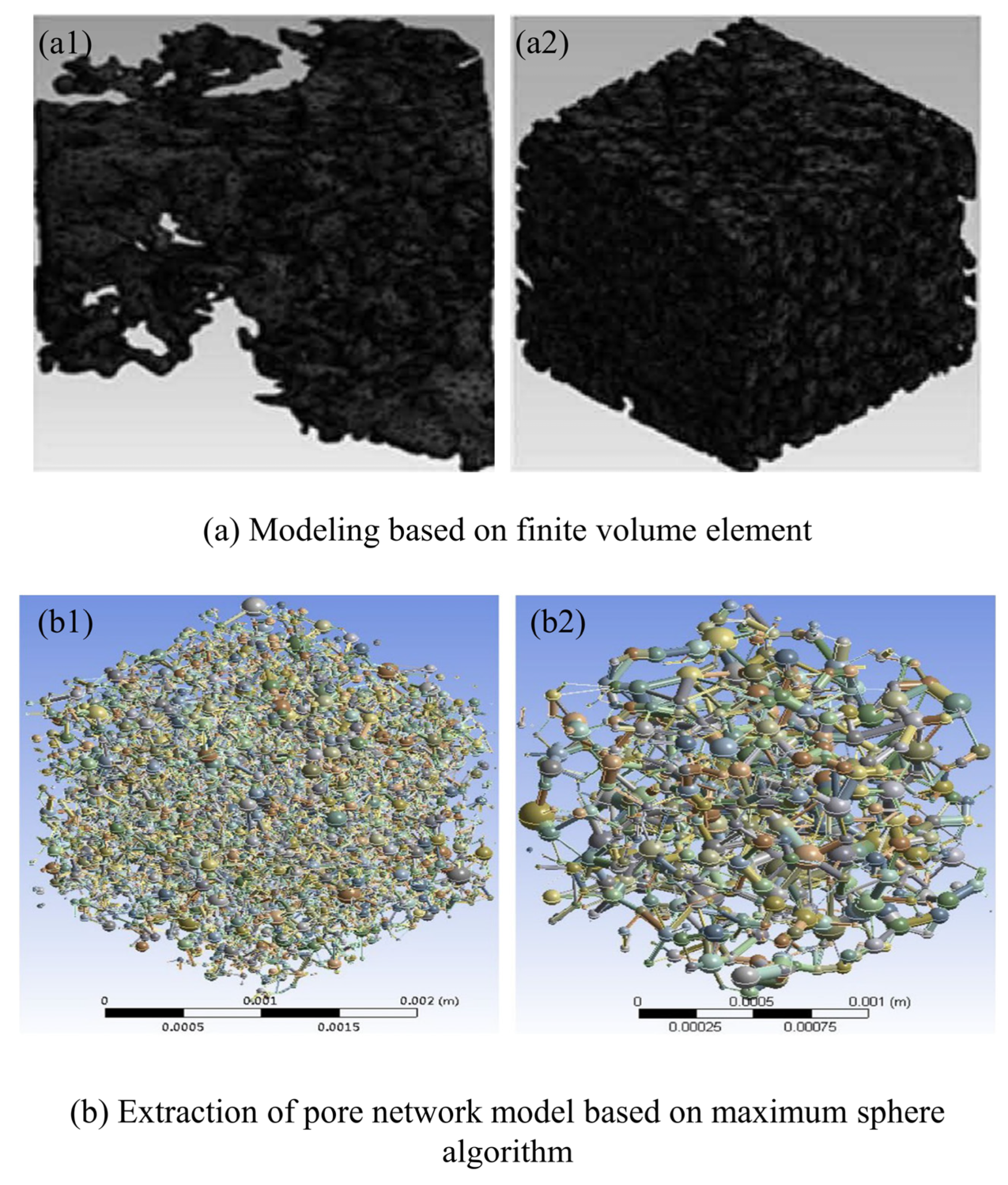
Figure 1. The new modeling method based on CT images: (a) images of the reconstructed porous samples in finite volume elements in the pore space (a1) size is 400 × 400 × 400 mm, (a2) size is 450 × 450 × 450 mm; (b) extraction of pore network models (EPNM) of the rock samples (b1) size is 2.14 mm, (b2) size is 1.46 mm [26,27].
Sustainability 15 12959 g001
Figure 2. Vertical stacked cross-section slices of CO2 saturation computed using CT data [41].
Sustainability 15 12959 g002
Figure 3. 2D images in the XY direction of the fluid distribution before and after CO2 flooding: (a) with cross-flow (b) without cross-flow [43].
Sustainability 15 12959 g003
Figure 4. Image of CO2 distribution during the sample drainage: (a) parallel injection; (b) vertical injection [45].
Sustainability 15 12959 g004
Figure 8. Final fluid distribution in a random heterogeneous system: (a) logCa = −4.36, (b) logCa = −4.16, (c) logCa = −4.06, (d) logCa = −3.59, (e) logCa = −3.36, and (f) logCa = −3.06 [73].
Sustainability 15 12959 g008
Figure 9. 3D distribution of CO2 in the heterogeneous samples with a different wettability [85].
Sustainability 15 12959 g009
Figure 10. Pore networks extracted from the images: (a) Estaillades, (b) Ketton, and (c) Mount Gambier [93].
Sustainability 15 12959 g010
Table 1. Absolute permeability of the simulation and experiment [26].
No.Size (10−3 m)Element NumberPorositykx/mDky/mDKz/mDKz/mD(exp.)
a11.326338,89917.83%8.265.153.563.35
a22.136561,15847.62%1646.921843.571245.11-
Table 2. Basic parameters of the models [27].
No.Size (mm)Number of PoresNumber of ThroatsAverage Connection NumberPorosity of EPNM (%)Experimental Porosity (%)EPNM/mD
b12.14629812,5583.9219.2718.731210
b21.4681015633.7213.7113.11872
Disclaimer/Publisher’s Note: The statements, opinions and data contained in all publications are solely those of the individual author(s) and contributor(s) and not of MDPI and/or the editor(s). MDPI and/or the editor(s) disclaim responsibility for any injury to people or property resulting from any ideas, methods, instructions or products referred to in the content.

