Article

Effects of Hydraulic Erosion on the Spatial Redistribution Characteristics of Soil Aggregates and SOC on Pisha Sandstone Slope

1
College of Desert Control Science and Engineering, Inner Mongolia Agricultural University, Hohhot 010018, China
2
Key Laboratory of Desert Ecosystem Conservation and Restoration, State Forestry and Grassland Administration of China, Hohhot 010018, China
3
Key Laboratory of Aeolian Physics and Desertification Control Engineering from Inner Mongolia Autonomous Region, Hohhot 010018, China
*
Author to whom correspondence should be addressed.
Sustainability 2023, 15(17), 13276; https://doi.org/10.3390/su151713276
Submission received: 18 August 2023 / Revised: 30 August 2023 / Accepted: 1 September 2023 / Published: 4 September 2023

Abstract

:
Under the long-term effects of hydraulic erosion, soil particles and nutrients are continuously lost and enriched in the process of runoff and sediment movement, leading to a change in soil organic carbon (SOC) in different spatial positions on the slope, which is closely related to the carbon balance of the ecosystem. Therefore, the changes in slope erosion intensity and the spatial redistribution characteristics of soil aggregates and SOC under water erosion conditions were quantitatively analyzed by combining field runoff plots with three-dimensional (3D) laser scanning technology. The results showed that: (1) After rainfall, the slope erosion intensity successively declined from the upper to the lower parts of the slope, and the content of soil aggregates in each soil layer changed obviously. The loss of 1–2 mm soil aggregates was the largest in the sedimentary area of the 2–4 cm soil layer, at 0.38 g/kg. The concentration of 0.5–1 mm soil aggregates was the largest in the micro-erosion area of the 2–4 cm soil layer, at 0.36 g/kg. (2) After rainfall, the overall SOC on the slope showed a loss state in the 0–2 cm soil layer and an enrichment state in the 2–4 cm soil layer. Among them, the loss of SOC in the medium erosion area of the 0–1 cm soil layer was the largest, and its content decreased by 57.58%. The enrichment in the 2–4 cm soil layer was the maximum in the micro-eroded area, with a content increase of 79.23%. (3) Before and after rainfall, the SOC of each soil layer was positively correlated with small aggregates, and the correlation gradually tended to be negative with the increase in the particle size of soil aggregates, and the SOC showed a negative correlation with large aggregates (>2 mm).

1. Introduction

Hydraulic erosion is the main reason for the dispersion and migration of soil particles on slopes [1]. As the basic unit of soil structures, soil aggregates are individuals formed by fine enough soil particles under the action of coagulation, cementation, and counter ions [2]. In the process of hydraulic erosion, splashed raindrops break the soil particles and destroy the soil structure. As a result, the soil structure migrates in the runoff direction, leading to the collision between aggregates and the surrounding environment and even the breakage of such aggregates. When dry soil is wetted by rainfall, the instantaneous osmotic pressure will also cause the soil aggregates to collapse due to rapid expansion. Therefore, each stage of hydraulic erosion includes the fragmentation, migration, and re-formation of soil aggregates [3,4].
As the largest and most active carbon pool in the terrestrial ecosystem, soil organic carbon (SOC) plays an important role in maintaining soil fertility and serves as an important factor in judging soil quality, accompanied by an important function in maintaining ecosystem productivity and stability [5]. Studies have shown that SOC usually exists in a combined state of coarse organic matter, fine granular organic matter, and soil minerals, and most of the coarse granular organic matter is concentrated in the soil surface layer and taken away relatively easily by runoffs [6]. As the basic unit of soil structure, soil aggregates are formed by the aggregation, flocculation, and cementation of soil particles [7,8]. In this formation mechanism, rich SOC is wrapped by or bonded on the surface of soil aggregates to exert physical protection, and organic carbon, as a cementing material, can also promote the formation and stability of aggregates [9]. Therefore, it can be judged that maintaining the stability of soil aggregates is an important way to realize SOC accumulation [10].
In recent years, research on soil carbon sequestration has been widely concerned. Among many studies, the physical protection mechanism of the aggregate structure on SOC is a research hotspot [11]. Previous studies have shown that the agglomeration of differently sized soil particles is one of the important ways to achieve carbon sequestration [12], and studying the carbon distribution in aggregates with different particle sizes is an important means of understanding the spatial redistribution characteristics of SOC [13]. At the same time, a large number of studies have revealed that hydraulic erosion directly drives the enrichment and migration of SOC to a certain extent, which leads to changes in soil physical and chemical properties in different spatial positions and changes the spatial distribution pattern of SOC with the occurrence and evolution of erosion, forming erosion areas and sedimentary areas and endowing them with strong spatial redistribution ability [14,15,16]. However, little is known about the redistribution characteristics of SOC in soil aggregates of different particle sizes during transportation and deposition under hydraulic erosion [17,18]. Therefore, deeply analyzing the coupling mechanism between geomorphic reconstruction and spatial redistribution of SOC under hydraulic erosion [19] will be of great significance for exploring soil carbon balance in the terrestrial ecosystem.
Pisha sandstone is a kind of rock interlayer composed of thick sandstone, sand shale, and argillaceous sandstone. The quartz content in the rock layer is lower than that of other rocks, the diagenesis degree of the rock layer is low, and the composition of the rock layer is mainly composed of feldspar, which is easy to weather, and montmorillonite, which is easy to expand in water. The degree of cementation between sand particles is poor, and the structural strength is low. The unique rock formation and mineral composition is one of the reasons for the easy erosion of Pisha sandstone. As a result, soil and water resources in the region are seriously lost, and SOC migrates with soil loss in the region, and soil quality is seriously decreased, as well as the decline of soil quality [20]. In previous studies, the relationship between soil aggregates and SOC under soil compounding conditions in the Pisha sandstone area has been mostly explored so as to evaluate the applicability of Pisha sandstone and sand–soil mixture [21,22]. For studies solely regarding SOC, only its spatial variability characteristics have been discussed [23]. The influence of soil aggregates on the spatial redistribution of SOC during migration has been less probed. In this paper, a bare sandstone slope without soil cover and vegetation cover was selected as the research object; therefore, in situ monitoring of field runoff plots under natural rainfall conditions was performed in this study to investigate the spatial migration law of soil aggregates and SOC in the two rainy seasons during 2019–2020. Moreover, the dynamic geomorphic change process was combined to explore the influence of soil aggregates with different particle sizes on the spatial redistribution of SOC during migration. Then, the relationship between soil particles and carbon balance in the Pisha sandstone area under hydraulic erosion was revealed, thus providing data support for improving the soil and carbon loss status caused by hydraulic erosion in this area, reasonably carrying out water and soil conservation and ecological restoration work and contributing to the improvement of the ecological environment in the Yellow River basin.

2. Materials and Methods

2.1. Overview of the Study Area

The study area is located in Nuanshui Town (39° 46′–39° 48′ N, 110° 31′–110° 35′ E) in Zhungeer Banner, Ordos City, Inner Mongolia, with an altitude of 1145–1330 m, and it is high in the north and low in the south (Figure 1). It has a temperate continental climate, with cold and dry winters and short and warm summers. The temperature in the annual range is very high, and the daily range is also very large. The annual temperature range in this area is 7.2 °C, the average annual rainfall is 400 mm, and the frost-free period is about 150 d. The dominant soil types are chestnut soil and aeolian sandy soil, with thin topsoil, loose soil structure, rich lime (Table 1), undulating terrain, criss-crossing ravines and gullies, and serious soil erosion. The vegetation is mainly perennial herbs and a few shrubs and trees, including Caragana korshinskii, Hippophae rhamnoides, Pinus tabuliformis, Leymus chinensis, and Salsola collina.

2.2. Experimental Design

2.2.1. Selection and Layout of Sample Plots

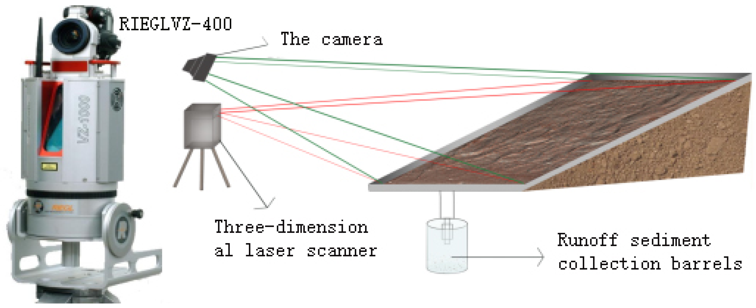
The experiment was prepared from 30 June 2019, and observation was performed in two rainy seasons (June–August) during 2019–2020. The study area is located in the Geqiugou watershed in Nuanshui Town of Zhungeer Banner, Ordos City, Inner Mongolia. According to the local actual situation, the exposed sandstone slope with a slope of 30° was selected as the study object. Before the start of the experiment, weeds, litter, and other sundries in the plot were cleared to reduce the impact on scanning. A runoff plot with a specification of 5 m (length) × 2 m (width) was set at two sides, of which 4 steel plates (5 m (length) × 0.5 m (width)) were arranged. Additionally, steel plates with a specification of 2 m (length) × 0.5 m (width) were set on the upper part. All steel plates were driven into the ground with a rawhide hammer for 30 cm with 20 cm reserved aboveground to block runoff outside the plot and prevent water from infiltrating into the boundary. Efforts were made to avoid the disturbance caused by the fixation of the rawhide hammer to the soil status on the slope. The long boundary of the plot was perpendicular to the contour line, with a water outlet at the bottom and a collecting bucket for collecting water and sediment samples (Figure 2). A fixed HOBO meteorological station was set up beside the runoff plot, the atmospheric precipitation process was recorded using a siphon self-counting recording rain meter, and a rainfall gauge was provided for cross-checking. Moreover, basic data such as rainfall, rainfall intensity, and rainfall duration were measured.

2.2.2. Terrain Monitoring

A RIEGLVZ-400 3D laser scanner was used to investigate the topographic vectorization characteristics of the slope before and after each rainfall. The scanning accuracy of the 3D laser scanner used in the experiment (100 m in each measurement) was 2 mm (horizontal accuracy) × 2 mm (vertical accuracy), and the vertical scanning range of the instrument was 0–270° and the horizontal range was 0–360°. A fixed cement pile was set at the bottom, top, left, and right sides of the runoff plot as the scanning site (Figure 2), and 5–8 fixed reference points were selected as the splicing reference points after data scanning at each station. Finally, the 3D laser scanner was erected and fixed on the horizontal ground about 2 m below the slope with a tripod, whose fixed height was 105 cm, and its position was marked to ensure the consistency of scanning conditions. The runoff plot was scanned once before rainfall to obtain the initial point cloud data on the slope surface, and then scanned again after each rainfall upon complete infiltration of water on the slope surface to obtain the morphological characteristics of the eroded slope surface. The obtained point cloud data on the slope were exported in the supporting Riscan-Pro v1.6.7 software, and the scanned 3D data were processed using ArcGis 10.2 software to construct a digital elevation model (M-DEM) with an accuracy of 2 mm × 2 mm.

2.2.3. Soil Collection and Sample Determination

Soil samples on the slope were collected using the grid sampling method. Six sampling points were evenly selected on the slope (within the range of 0–2 m from the top of the runoff plot), in the slope (within the range of 2–3.5 m from the top of the runoff plot), and under the slope (within the range of 3.5–5 m from the top of the runoff plot), totaling 18 sampling points. Because the erosion depth of the eroding ills in the slope runoff plot could only reach 4 cm, the soil samples were evenly collected from three soil depths—0–1 cm, 1–2 cm, and 2–4 cm—by a self-made small-hole soil drill, considering the soil layer thickness in the Pisha sandstone area and the degree of slope failure. Soil aggregates were determined using the Le Bissonnais method. For SOC determination, the soil sample was spread into a thin layer of 2–3 cm and was naturally air-dried. After thorough air drying, the sample was passed through a 2 mm soil sieve and further finely ground. On this basis, SOC was determined using an Lh-Soc350 SOC determinator.

2.3. Data Processing

The slope erosion area and sedimentary area were extracted by ArcGis10.8 software, and the SOC and aggregates before and after rainfall were subjected to descriptive statistical analysis via SAS9.0 software and a single-factor Duncan test (significance level: α = 0.05). In addition, drawing was performed using Origin 2021 and ArcGIS 10.8.

3. Results and Analysis

3.1. Slope Erosion Intensity Analysis

Hydraulic erosion reshapes the landform by changing the surface elevation, and the intensity of slope erosion is often reflected by the depth of slope erosion, the area of erosion deposition, and the number of pixels. In this section, the slope erosion after each of the 13 effective rainfalls in two rainy seasons in the study area from 2019 to 2020 was investigated and counted (Table 2). It was found that among the 13 effective rainfalls in the two rainy seasons, the erosion depth of two rainfalls was 0–1 cm, that of three rainfalls was 1–2 cm, that of five rainfalls was 2–3 cm, and that of three rainfalls was >3 cm. By comparing the number of pixels after each rainfall, it was discovered that the number of pixels with an erosion depth of 0–1 cm was the largest, and the erosion area of the eighth rainfall was the smallest, with 106 pixels, accounting for 6.2% of the whole slope. The ninth rainfall led to the largest erosion area, with 14,650 pixels, accounting for 85%. It can be seen from Table 2 that after the second rainfall, the number of rainfalls with erosion depths of only 0–1 cm was very small, and the erosion depth of the slope was mainly 2–3 cm. Only a small proportion of rainfalls could result in an erosion depth of >3 cm, and when the erosion depth reached 2–3 cm, the erosion area was larger than the non-eroded area.
M-DEM clearly displayed the soil erosion intensity of the slope inside the runoff plot. By subtracting the M-DEM after rainfall from that before rainfall, the slope erosion status after 13 effective rainfalls in two rainy seasons in 2019–2020 was obtained (Figure 3). According to the erosion depth, the slope erosion status was divided into 5 grades, namely 0–1 cm micro-erosion, 1–2 cm slight erosion, 2–3 cm moderate erosion, and >3 cm heavy erosion, and those with erosion depth greater than 0, which were regarded as sedimentary areas. It can be seen from Figure 3 that the heavily eroded area on the slope was mainly located in the upper part of the slope, while a lot of sedimentary areas (erosion depth < 0 cm) were largely distributed in and under the slope. Micro and slightly eroded areas were mainly distributed in the slope. It can be seen that when the gradient of the bare Pisha sandstone slope was 30°, the erosion intensity was obviously weakened from the top to the bottom of the slope, the erosion event appeared at the top of the slope in the whole plot, and the deposition event mainly occurred at the bottom of the slope, while on the slope, plaque fragmentation was serious with poor continuity.

3.2. Spatial Redistribution Characteristics of Soil Aggregates

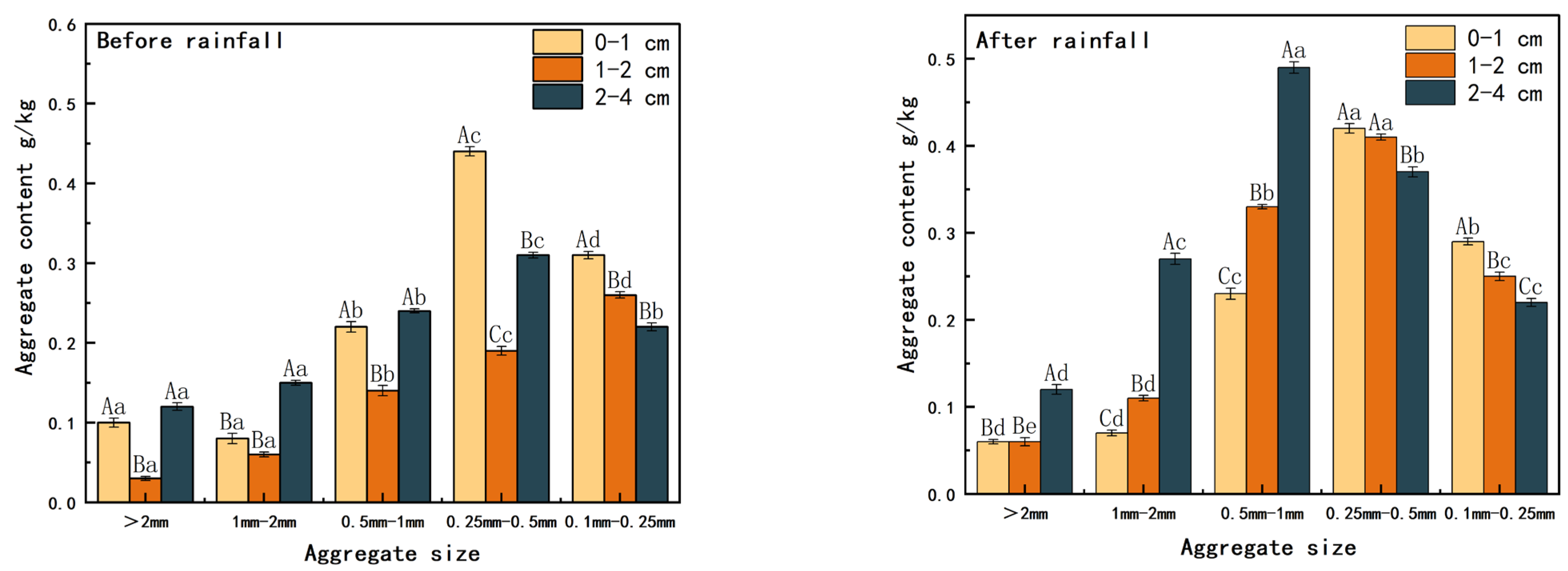
The content of soil aggregates in different soil layers (0–1 cm, 1–2 cm, and 2–4 cm) was different before and after rainfall. It can be seen from Figure 4 that the soil aggregate particles >0.5 mm were mainly distributed in the soil layer of 2–4 cm before rainfall, with a content of 0.01–0.55 g/kg. The 0.1–0.5 mm soil aggregate particles were widely distributed in the soil layer of 0–1 cm. After rainfall, soil aggregate particles >0.5 mm were also mainly distributed in the soil layer of 2–4 cm, with a content of 0.01–0.26 g/kg, the average content of soil aggregates >0.5 mm was larger than that before rainfall in all soil layers, and the aggregate content increased with the increase in soil thickness. After rainfall, 0.1–0.5 mm soil aggregate particles decreased with the increase in soil depth. The content of 0.25–0.5 mm soil aggregates was the highest in the soil layer of 0–1 cm before rainfall, at 0.44 g/kg, and the content of 0.5–1 mm soil aggregates was the highest in the soil layer of 2–4 cm after rainfall, at 0.49 g/kg. Both before and after rainfall, 0.1–0.25 mm soil aggregates were reduced with the increase in soil depth, and their content in different soil layers was 0.19–0.61, 0.09–0.55, 0.04–0.43, 0.17–0.41, 0.09–0.51, and 0.06–0.51 g/kg, respectively.
The loss and enrichment of soil aggregates with different particle sizes on the slope could be clearly distinguished through the spatial distribution difference map of soil particle components in different soil layers before and after rainfall. The spatial distribution difference map (Figure 5) could be obtained by subtracting the spatial distribution status of soil aggregates with different particle sizes in the plot before rainfall from that after rainfall. As shown in Figure 5, soil aggregates with a particle size of >2 mm showed a loss state in the soil layer of 0–2 cm, and the loss area in the soil layer of 0–1 cm mainly occurred in the middle and upper part of the slope. However, the loss was the most serious in the soil layer of 1–2 cm, and almost the whole slope was subjected to loss. In the soil layer of 2–4 cm, the enrichment state played a dominant role, accompanied only by a small loss at the southeast and northwest sides of the slope. Soil aggregates with a particle size of 1–2 mm were enriched on the slope and lost under the slope in the soil layer of 0–1 cm, with a minor loss; the soil layer of 1–2 cm was dominated by the loss; an enrichment state was observed in the soil layer of 2–4 cm. Soil aggregates with a particle size of 0.5–1 mm were enriched in all soil layers, among which the enrichment was the maximum in the soil layer of 2–4 cm. Soil aggregates with a particle size of 0.25–0.5 mm were enriched in the soil layer of 0–2 cm, and the enrichment was large in the soil layer of 1–2 cm, but a great loss was found in the soil layer of 2–4 cm. Soil aggregates with a particle size of 0.1–0.25 mm were lost in all soil layers, and the loss was the most serious in the soil layer of 2–4 cm.
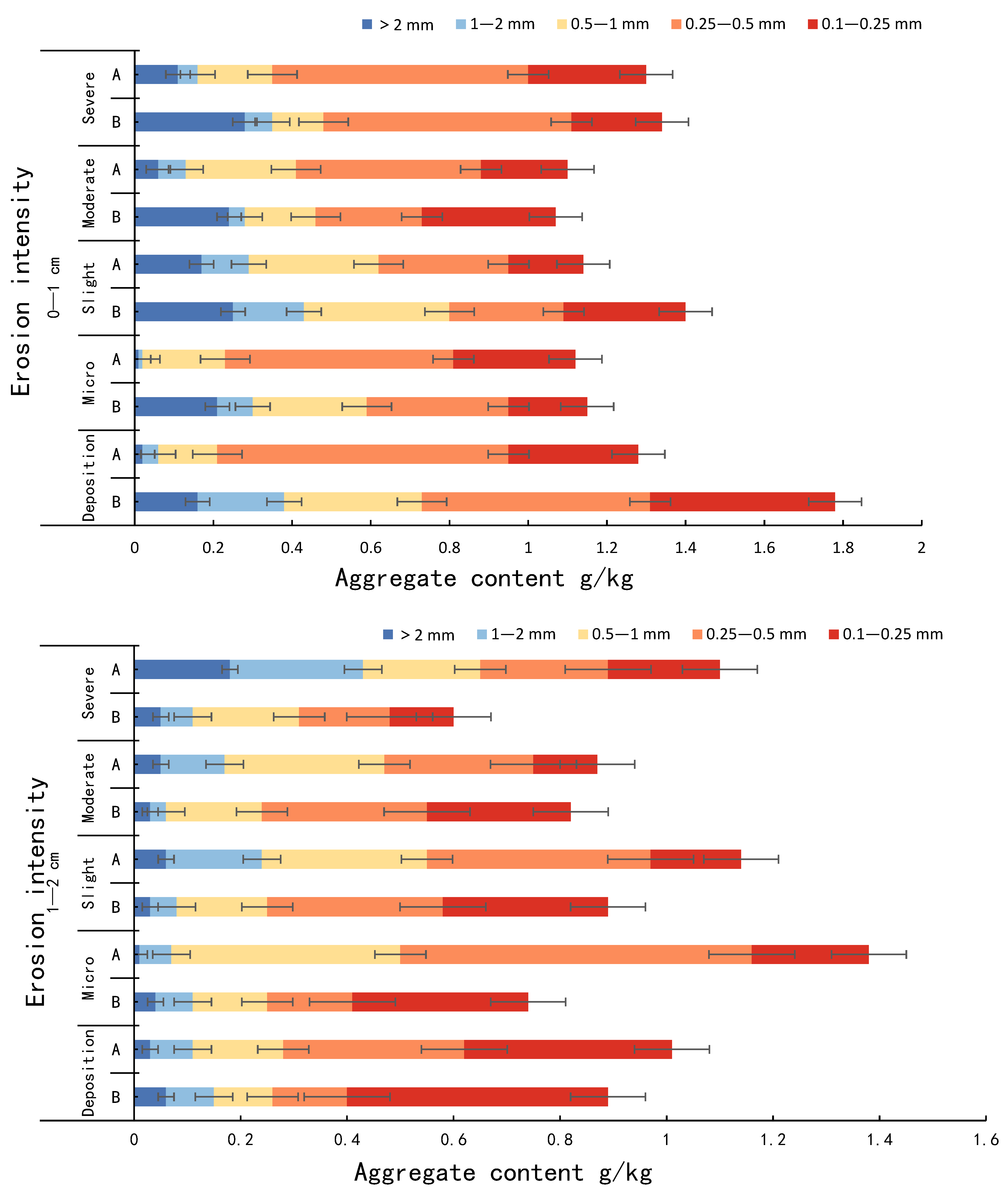
The spatial redistribution characteristics of soil aggregates after erosion could be better reflected by their content under different erosion intensities. The content variation characteristics of soil aggregates with different particle sizes before and after rainfall (Figure 6) showed that soil aggregates >0.5 mm in the 0–1 cm soil layer were in a state of loss on the whole slope, and the soil aggregates >2 mm experienced the largest loss in the moderately eroded area, at 0.18 g/kg. Soil aggregates of 0.25–0.5 mm were enriched under all erosion intensities, and the maximum enrichment in the micro-erosion area was 0.22 g/kg. Soil aggregates > 1 mm in the 1–2 cm soil layer were enriched in sedimentary areas and micro-eroded areas, while they were lost in other eroded areas. The 0.25–1 mm soil aggregates were enriched on the whole slope, and the 0.5–1 mm soil aggregates were enriched greatest in the micro-erosion area, with a content of 0.29 g/kg. The 0.1–0.25 mm soil aggregates reached the maximum loss in the moderate erosion area, at 0.15 g/kg. The loss of 1–2 mm soil aggregates in the 2–4 cm soil layer was the largest in the sedimentary area, at 0.38 g/kg, and the enrichment of 0.5–1 mm soil aggregates was the largest in the micro-eroded area, at 0.36 g/kg.

3.3. Spatial Variation Characteristics of SOC

From the spatial distribution of SOC on the whole slope before and after rainfall (Figure 7), the SOC content in each soil layer after rainfall was obviously lower than that before rainfall. Before rainfall, the SOC content in each soil layer was 0.01–0.50 g/kg, and the SOC content in the 0–1 cm soil layer was the highest, with a maximum value of 0.41 g/kg and an average value of 0.21 g/kg. The SOC content in the 1–2 cm soil layer was 0.01–0.35 g/kg, with an average of 0.16 g/kg. The maximum SOC content in the 2–4 cm soil layer was 0.46 g/kg, but only a few soil samples showed a high SOC content. The SOC content of the other soil samples was 0.01–0.20 g/kg. After rainfall, the SOC content in the 0–1 cm, 1–2 cm, and 2–4 cm soil layers were 0.04–0.26, 0.04–0.21, and 0.02–0.20 g/kg, respectively, with average values of 0.14, 0.12, and 0.10 g/kg, respectively. The SOC content decreased gradually from the top to bottom with the change of soil depth before and after rainfall, and a large amount of SOC was enriched in the topsoil. The CV (Coefficient of Variation) is commonly used to describe the dispersion between variables in geostatistics, which can be divided into three grades: strong variation (CV < 100%), weak variation (CV < 10%), and moderate variation (10% ≤ CV ≤ 100%). It can be seen from Figure 6 that the SOC of each soil layer showed moderate variation before and after rainfall, with the CV ranging from 57.26% to 61.65% and 44.33% to 54.41%, respectively, and the CV of SOC in each soil layer after rainfall was smaller than that before rainfall.
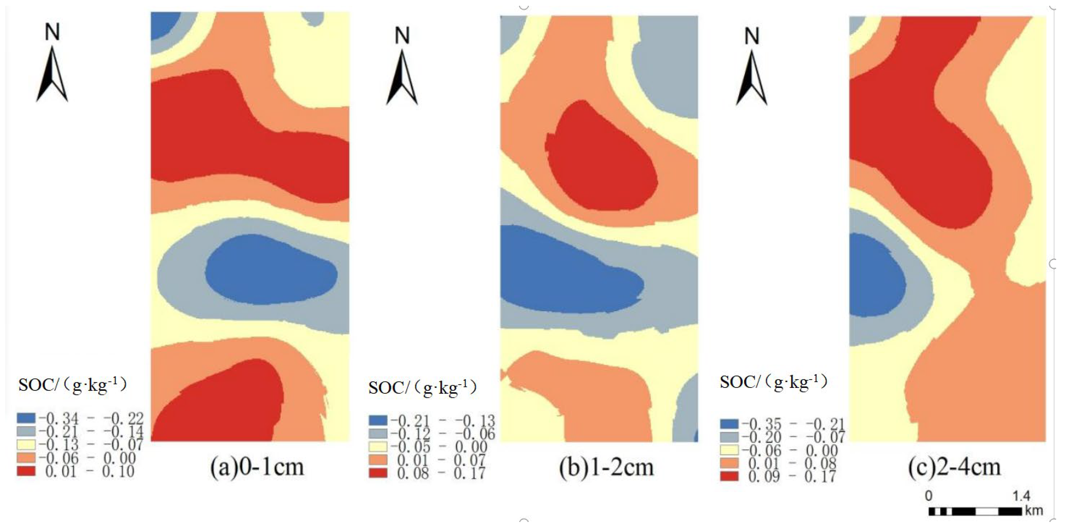
The SOC in soil samples from different soil layers (0–1, 1–2, and 2–4 cm) in the runoff plot was spatially interpolated using the Kriging interpolation method, and the data of the sampling points were displayed by continuous panel data. The spatial distribution difference map (Figure 8) of SOC before and after rainfall could be acquired by subtracting the spatial distribution graph of SOC on the slope before rainfall from that after rainfall. The erosion and enrichment of SOC on the slope before and after rainfall could be clearly observed through the difference map. After rainfall, the SOC content in the 0–2 cm soil layer showed a loss state as a whole; namely, the erosion area was larger than the sedimentary area, among which the SOC content reduction was the largest in the 0–1 cm soil layer with the largest erosion area. In addition, the severely eroded area ran through the whole slope, and the erosion on the slope was the most intense. The sedimentary range was large in the 2–4 cm soil layer, in which an overall enrichment state was manifested.
After hydraulic erosion, the SOC content under different erosion intensities could better reflect the influence of erosion on the spatial variation of SOC. The SOC content at different erosion intensity levels before and after rainfall was obtained by extracting the SOC spatial difference map in the eroded area and non-eroded area of each soil layer before and after rainfall (Figure 9). It can be seen from the figure that the SOC content in the 0–1 cm soil layer before rainfall was higher than that after rainfall. The highest SOC content before rainfall appeared in the moderately eroded area (0.25 g/kg), and the lowest value appeared in the micro-eroded area (0.20 g/kg). After rainfall, however, the highest and lowest values of SOC content appeared in the non-eroded area (erosion depth < 0) and moderately eroded area, at 0.15 and 0.14 g/kg, respectively. After rainfall, the SOC content in the 0–1 cm soil layer decreased significantly under all erosion intensities (p < 0.05). With the increase in erosion intensity, the SOC content decreased by 26.23%, 49.97%, 57.58%, and 44.49%, respectively, and the SOC loss was the most serious in the moderately eroded area, while the SOC content in the non-eroded area declined by 25.07%. The SOC content in the 1–2 cm soil layer did not change obviously before and after rainfall, among which the SOC content in the micro-eroded area increased significantly (p < 0.05), while that under other erosion intensities decreased significantly (p < 0.05) by 2.83 times, 10.78 times, and 20.33% in slightly, moderately, and severely eroded areas, respectively, and increased by 1.23 times in the micro-eroded area, and that in the non-eroded area declined by 10.51%. The SOC content in the 2–4 cm soil layer increased significantly compared with that before rainfall (p < 0.05). With the increase in erosion intensity, the SOC content increased by 1.79, 1.56, 1.54, and 1.29 times, respectively, and the SOC content in the micro-eroded area increased the most, while that in the non-eroded area increased by 1.40 times.

3.4. Effects of Soil Aggregates on the Spatial Redistribution of SOC

Soil aggregate is the most basic structural unit of soil, and the change in its content will affect the carbon sequestration capacity of soil and the stability of soil structure. Therefore, exploring the change of soil aggregates in the erosion process is the key to investigating the spatial redistribution of SOC. By analyzing the correlation between SOC content and the particle size of soil aggregates in different soil layers, it could be known that before rainfall (Table 3), the SOC in each soil layer was negatively correlated with >2 mm large soil aggregates, with correlation coefficients of −0.011, −0.054, and −0.136, and positively correlated with 0.1–0.25 mm microaggregates, with correlation coefficients of 0.358, 0.244, and 0.393, respectively. Therein, the SOC in the 0–1 cm soil layer showed a positive correlation with 0.1–1 mm soil aggregates and a negative correlation with 0.25–1 mm and >2 mm soil aggregates, and it was positively correlated with soil aggregates of other particle sizes. The SOC in the 2–4 cm soil layer was negatively correlated with >0.5 mm soil aggregates and positively correlated with the 0.1–0.5 mm soil aggregates.
After rainfall, the correlations in all soil layers increased, and the correlation coefficients with >2 mm large soil aggregates were −0.110, −0.240, and −0.255, and the SOC was significantly positively correlated with 0.1–0.25 mm micro-aggregates (p < 0.05), with coefficients of 0.493, 0.277, and 0.402, respectively. Among them, the SOC in the 0–1 cm soil layer was negatively correlated with 0.1–0.25 mm soil aggregates and positively correlated with 0.1–0.25 mm soil aggregates. The SOC in the 1–2 cm soil layer was negatively correlated with >0.25 mm soil aggregates, and positively correlated with 0.1–0.25 mm soil aggregates. The SOC in the 2–4 cm soil layer was negatively correlated with >0.5 mm soil aggregates, and positively correlated with 0.1–0.5 mm soil aggregates.
Generally speaking, the SOC in all soil layers had a positive correlation with small aggregates (<0.25 mm) before and after rainfall and tended to be negatively correlated with the increase of aggregate particle size, and it was negatively correlated with large aggregates (>0.5 mm). Hence, it can be concluded that small soil aggregates on the Pisha sandstone slope are a key factor deciding the SOC content after redistribution.

4. Discussion

4.1. Spatial Redistribution Characteristics of Soil Aggregates under Different Erosion Intensities

Hydraulic erosion is one of the most important causes of soil loss. Under the long-term action of hydraulic erosion, soil particles and nutrients are constantly losing and enriching in the process of runoff and sediment movement, which leads to changes in soil physical and chemical properties in different spatial positions, and with the occurrence and evolution of the erosion process, erosion areas and sedimentary areas in different soil environments are formed [24]. Meanwhile, this process also drives changes in surface morphology. With the change in the position of the soil itself and the rise and fall of the elevation value, the slope morphology is reshaped [25]. In this study, the change in slope micro-topography after rainfall showed that the erosion degree decreased from the top to the bottom of the slope, and the sedimentary area was located at the bottom of the slope, which was consistent with the study results of Li et al. [19]. The reason is that when raindrops reach the ground, part of the sediment will be displaced along the slope during the erosion process and enriched due to gravity when they reach the low-lying place under the slope, leading to an erosion state on the slope and a deposition state under the slope.
In the 0–1 cm soil layer, >0.5 mm soil aggregates were lost under all erosion intensities. This is because >0.5 mm soil aggregates are located in the topsoil of the slope, raindrops directly act upon the surface of soil particles when dripping, and thus large aggregates are broken and disintegrated and move with the runoff, resulting in a massive loss of >0.5 mm soil aggregates. This coincides with the results of Gordon et al. [3]. The loss of 1–2 mm soil aggregates was the largest in the sedimentary area of the 2–4 cm soil layer, at 0.38 g/kg. A possible reason is that during rainfall, a large amount of runoff generated on the slope surface is collected in the sedimentary area under the slope; thus, the original aggregates with a larger particle size of 1–2 mm in the 2–4 cm soil layer are wetted by water. In addition, such aggregates become mud when encountering water due to the special mineral composition of Pisha sandstone, and as a result, 1–2 mm aggregates are disintegrated and transformed into small aggregates when meeting water. The 0.5–1 mm soil aggregates were enriched greatest in the micro-eroded area, with a content of 0.36 g/kg, and such aggregates were enriched in all soil layers. This is possibly because >1 mm soil aggregates are crushed under rainfall action and transformed into 0.5–1 mm aggregates or aggregates with other particle sizes and carried away by runoff. When runoffs are generated, the water flow is gathered downward along the slope, so the soil water content in the micro-eroded area is smaller than that in the sedimentary area, accompanied by the unobvious fragmentation of soil particles. Hence, the enrichment of 0.5–1 mm soil aggregates was large in the micro-eroded area.

4.2. Causes of Hydraulic Erosion-Induced SOC Migration

The runoff generated during rainfall drives sediment to migrate, causing soil erosion and simultaneously driving SOC to migrate and be enriched. This physical process directly changes the distribution pattern of soil carbon in the ecosystem [26]. The SOC content in the study area was generally at a low level and decreased with the increase in soil depth, which might be ascribed to the arid climate in the soft sandstone area, soil depletion, high microbial activity in the soil surface, and the decomposition and transport of nutrients by the above-ground litter. The deeper the soil layer, the less animal and plant residues. Moreover, the main mineral components of Pisha sandstone are quartz, calcium montmorillonite, potash feldspar, and calcite, and the rock structure is hard and difficult to penetrate by plant roots when it is not exposed to water, thus absorbing very little organic matter. This is consistent with the study of Liang et al. [27]. In this study, the SOC difference in the 0–1 cm soil layer before and after rainfall was the most significant (p < 0.05), and Wei also obtained the same study result [28]. The reason is that the topsoil is more easily disturbed by water erosion, resulting in a stronger response to erosion and a larger loss. However, the content of organic carbon in the 2–4 cm soil layer was higher than that before rainfall. According to the study of Ma, it can be considered that SOC is vertically leached from topsoil to deep soil under the influence of hydraulic erosion [29]. The SOC of each soil layer on the slope before and after rainfall varied moderately. The CV of each soil layer after rainfall was smaller than that before rainfall, indicating that rainfall can slow down the degree of variation in SOC to some extent, which is consistent with the result obtained by Li et al. (2021) [19]. After rainfall, the SOC in the 0–2 cm soil layer showed a state of loss as a whole, and the SOC in the 2–4 cm soil layer was more abundant than that in the other soil layers. The reason is that raindrops directly act on the topsoil, which leads to serious erosion of the 0–1 cm soil layer and an increasing number of distributed erosion areas. In the process of erosion, part of SOC moves along the slope to reach the low-lying place under the slope and is enriched due to gravity, which results in a loss state on the slope and an enrichment state under the slope. The enriched organic carbon may be taken away in the next erosion section to participate in a new round of physical migration or deposited and sealed by the sediment washed down from the slope. During the horizontal migration of SOC along the slope, SOC will be gathered towards deeper soil layers under the action of vertical leaching, so an enrichment state is observed in the 2–4 cm soil layer, which coincides with the study of Fullen et al. [30]. Therefore, hydraulic erosion is a critical factor leading to the spatial redistribution of SOC. Under hydraulic erosion, a new spatial distribution pattern of SOC is formed no matter through horizontal migration, vertical leaching or deposition and sealing.
Through the above analysis, it is found that the external force generated by raindrop splashing is one of the important causes of SOC loss on the slope. Vegetation measures are the key measures used to prevent SOC loss. On the slope scale, vegetation can effectively intercept surface runoff, slow down its flow rate, promote sediment deposition, weaken or eliminate the erosion energy of rainfall and runoff to a large extent, and reduce the chance of erosion. The specific performance of vegetation is that vegetation cover can reduce the raindrop kinetic energy, thereby reducing erosion caused by erosion, and can prevent SOC loss through the integrated effects of above-ground canopy interception of rain, underground root system reinforcement of soil to increase erosion resistance, promotion of infiltration, and surface coverage and runoff mitigation.

4.3. Relationship between Soil Aggregates and Spatial Redistribution of SOC

Rainfall and runoff are the most important power sources in the migration process of soil particles and their nutrients on the slope, which can directly act on the surface of eroded soil, thus leading to the dispersion and transportation of tiny soil particles during rainfall and the further massive loss of soil nutrients. According to the study by Martinez-Mena et al. [31], the kinetic energy of rainfall is the most critical factor affecting the movement of original soil particles or aggregates with water flow, and raindrops erode the soil surface in the process of rainfall, which inevitably results in the fragmentation and loss of soil aggregates and then soil erosion [32]. In the process of soil erosion, soil aggregates move with water flow under the joint action of raindrop blowing and runoff scouring, so the spatial distribution characteristics of soil aggregates and SOC before rainfall are greatly different from those after rainfall. It was found in this study that before and after rainfall, a lot of >0.5 mm soil aggregates were distributed in the 2–4 cm soil layer, while 0.1–0.5 mm soil aggregates were distributed in the 0–1 cm soil layer, and the content after rainfall was always higher than that before rainfall. The soil aggregates with the 4 particle sizes of >0.25 mm were enriched in the 2–4 cm soil layer, and 0.1–0.25 mm soil aggregates were eroded in all soil layers. When studying the breakage and migration mechanism of five types of soil aggregates (loose fill, cinnamon soil, dark loessal soil, loessal soil, and aeolian sandy soil) in the Loess Plateau area, Fu et al. [33] found that the mass percentages of the five types of large soil aggregates (>0.25 mm) grow significantly with the increase of raindrop diameter or discharge flow. This also verifies that >0.25 mm aggregates are deposited a lot in the process of hydraulic erosion, during which SOC is usually wrapped by or bonded on the surface of soil aggregates, thus leading to the change in their spatial position. Therefore, the migration law of SOC carried by soil particles with different particle sizes during hydraulic erosion can be more deeply understood by comparatively analyzing the correlation between the content of soil aggregates with different particle sizes and SOC. It was found in this study that before and after rainfall, the SOC in all soil layers was positively correlated with small aggregates (0.1–0.25 mm), and the correlation gradually tended to be negative with the increase of the particle size of soil aggregates, and it exhibited a negative correlation with large aggregates (>0.5 mm). Therefore, small soil aggregates on the Pisha sandstone slope constitute a key factor in determining the SOC content after redistribution. However, the study by Aksakal et al. found that macroaggregates usually have more organic matter and higher nutrient levels, are less susceptible to erosion, and produce larger pores for better water infiltration and aeration, and that management practices on the ground in general have a greater impact on macroaggregates than microaggregates [34]. This is inconsistent with the characteristics of soil aggregates on arsenic sandstone slopes in the present study, probably due to the significant difference in the spatial heterogeneity of soil thickness and the complexity of the underlying bedding surface in the arsenic sandstone area compared to other study areas, coupled with the unique diagenetic structure of the arsenic sandstone, which results in the arsenic sandstone having the characteristics of becoming mud in the case of water, and sand in the case of wind leading to a more pronounced erosive effect of its microaggregates when subjected to the action of external camping forces.

5. Conclusions

(1) After rainfall, the slope erosion intensity was successively weakened from the upper to the lower parts of the slope, while the sedimentary area was located at the bottom of the slope. After hydraulic erosion, the soil aggregates in all soil layers were lost or enriched. >2 mm soil aggregates reached the maximum loss in the moderately eroded area in the 0–1 cm soil layer, being 0.18 g/kg. The 1–2 mm soil aggregates were lost greatest in the moderately eroded area in the 2–4 cm soil layer, at 0.38 g/kg. The enrichment of 0.5–1 mm soil aggregates was the maximum in the micro-eroded area, at 0.36 g/kg. The 0.25–0.5 mm soil aggregates were enriched in all soil layers, where the enrichment in the sedimentary area in the 2–4 cm soil layer was the maximum, at 0.22 g/kg. The 0.1–0.25 mm soil aggregates reached the maximum loss in the moderately eroded area in the 2–4 cm soil layer, at 0.23 g/kg.
(2) After hydraulic erosion, the content of SOC in all eroded areas in the 0–1 cm soil layer decreased, while that in the micro-eroded area in the 1–2 cm soil layer increased, that in other erosion areas of this soil layer decreased, and that in all erosion areas in the 2–4 cm soil layer increased. The SOC change was the largest in the moderately eroded area in each soil layer. As the erosion intensity increased, the SOC content grew by 1.79, 1.56, 1.54, and 1.29 times, respectively. The increase of SOC content was the maximum in the micro-eroded area, and the SOC content in the non-eroded area grew by 1.40 times.
(3) Generally, the SOC of each soil layer had a positive correlation with small aggregates (0.1–0.25 mm) before and after rainfall, and the correlation gradually tended to be negative with the increase in the particle size of soil aggregates. In addition, the SOC content was negatively correlated within large aggregates (>0.5 mm).

Author Contributions

Conceptualization, P.Z. and L.L.; Data curation, Funding acquisition, P.Z. and L.L.; Investigation, Resources, Writing—review & editing, Project administration, P.Z., J.W., Z.Z. and S.Z. All authors have read and agreed to the published version of the manuscript.

Funding

National Natural Foundation of China, Mutual Feed Mechanism between Spatiotemporal Variation of slope erosion and Vegetation Patch Pattern Evolution of Psasandstone (42267049), Improving the scientific research ability of young teachers: Spatial-temporal Variation of hydraulic erosion under different slope Vegetation patterns in the Yellow River Basin (BR220109), Central Government Guided Local Science and Technology Development Fund Project: Study on the mutual Feed Mechanism between Hydraulic erosion Process and Vegetation Patch Pattern Evolution of Psasandstone Slope (2021ZY0023), Inner Mongolia Autonomous Region Science and Technology Plan project, the Yellow River Ten Kongdui Basin ecological restoration space accurate identification and smart soil and water conservation technology (2021GG0052) second topic.

Institutional Review Board Statement

Not applicable.

Informed Consent Statement

Informed consent was obtained from all subjects involved in the study.

Data Availability Statement

Data are available on request due to restrictions.

Acknowledgments

We thank Li Long from Inner Mongolia Agricultural University in Hohhot, China, and the Key Laboratory of Desert Ecosystem Conservation and Restoration of the State Forestry Administration for providing us with the experimental site.

Conflicts of Interest

The authors declare no conflict of interest.

References

  1. Gintaras, J.; Witoniak, M.; Kinderien, I. Dynamics of slope processes under changing land use conditions in young morainic landscapes, Western Lithuania. Int. Agrophys. 2020, 1, 43–55. [Google Scholar]
  2. Anderson, R.; Brye, K.R.; Wood, L.S. Soil Aggregate Stability as Affected by Landuse and Soil Properties in the Lower Mississippi River Valley. Soil Sci. Soc. Am. J. 2019, 83, 1512. [Google Scholar] [CrossRef]
  3. Gordon, H.; Haygarth, P.M.; Bardgrtt, R.D. Drying and rewetting effects on soil microbial community composition and nutrient leaching. Soil Biol. Biochem. 2008, 40, 302–311. [Google Scholar] [CrossRef]
  4. Teh, C.B.S. The Stability of Individual Macroaggregate Size Fractions of Ultisol and Oxisol Soils. J. Agric. Ence Technol. 2012, 14, 459–466. [Google Scholar]
  5. Regina, S.; Jūratė, A.; Donata, T.; Gintaras, S. Impact of sward formation on soil organic carbon variation and relations with soil microbial activity. Zemdirb.-Agric. 2022, 109, 195–202. [Google Scholar] [CrossRef]
  6. Zhao, P.; Li, L.; Lin, L.; Zhai, G.; Cruse, R.M.; Wang, E. Response of surface soil nutrients and organic carbon fractions to tillage erosion vs. Water erosion in an agricultural landscape. Soil Sci. Soc. Am. J. 2022, 86, 1470–1482. [Google Scholar] [CrossRef]
  7. Jennifer, A.J.; Dungait, D.W.; Hopkins, A.S.; Gregory, A.P.; Whit, M. Soil organic matter turnover is governed by accessibility not recalcitrance. Global Change Biol. 2016, 18, 1781–1796. [Google Scholar] [CrossRef]
  8. Arunrat, N.; Sereenonchai, S.; Kongsurakan, P.; Hatano, R. Soil organic carbon and soil erodibility response to various land-use changes in northern Thailand. Catena 2022, 219, 106595. [Google Scholar] [CrossRef]
  9. Song, K.; Yang, J.J.; Xue, Y.; Lv, W.G.; Zheng, X.Q.; Pan, J.J. Influence of tillage practices and straw incorporation on soil aggregates, organic carbon, and crop yields in a rice-wheat rotation system. Sci. Rep. 2016, 6, 36602. [Google Scholar] [CrossRef]
  10. Causarano, H.J.; Doraiswamy, P.C.; McCarty, G.W.; Hatfield, J.L.; Milak, S.; Stern, A.J. EPIC modeling of soil organic carbon sequestration in croplands of Iowa. J. Environ. Qual. 2008, 37, 1345–1353. [Google Scholar] [CrossRef]
  11. Bronick, C.J.; Lal, R. Soil structure and management: A review. Geoderma 2005, 124, 3–22. [Google Scholar] [CrossRef]
  12. Wang, J.G.; Yu, B.; Ni, S.M.; Guo, Z.L.; Cai, C.F. Effects of sediment load on the abrasion of soil aggregate and hydraulic parameters in experimental overland flow. J. Integr. Agric. 2020, 19, 1117–1126. [Google Scholar] [CrossRef]
  13. Lal, R. Accelerated Soil erosion as a source of atmospheric CO2. Soil Tillage Res. 2019, 18, 35–40. [Google Scholar] [CrossRef]
  14. Berhe, A.A.; Harte, J.; Harden, J.W.; Torn, M.S. The significance of the erosion—induced terrestrial carbon sink. BioScience 2007, 57, 337. [Google Scholar] [CrossRef]
  15. Gao, L.Q.; Matthew, A.; Bowker Sun, H.; Zhao, J.; Zhao, Y.G. Linkages between biocrust development and water erosion and implications for erosion model implementation. Geoderma 2020, 357, 113973. [Google Scholar] [CrossRef]
  16. Olson, K.R.; An, G. Dynamics of soil organic carbon storage and erosion due to land use change (Illinois, USA). Eurasian Soil Sci. 2020, 53, 436–445. [Google Scholar] [CrossRef]
  17. Tong, L.S.; Fang, N.F.; Xiao, H.B.; Shi, Z.H. Sediment deposition changes the relationship between soil organic and inorganic carbon: Evidence from the Chinese Loess Plateau. Agric. Ecosyst. Environ. 2020, 30, 107076. [Google Scholar] [CrossRef]
  18. Zeng, Y.; Fang, N.F.; Shi, Z.H.; Lu, X.X.; Wang, Z.G. Soil Organic Carbon Redistribution and Delivery by Soil Erosion in a Small Catchment of the Yellow River Basin. J. Geophys. Res.-Biogeosci. 2020, 125, 1–16. [Google Scholar] [CrossRef]
  19. Li, L.; Qin, F.C.; Yang, X.L.; Jiang, L.N.; Dong, X.Y.; Ren, X.T. Relationship between the slope microtopography and the spatial redistribution pattern of soil organic carbon under water erosion. J. Soil Water Conserv. 2021, 76, 435–445. [Google Scholar] [CrossRef]
  20. Zhang, P.; Xiao, P.Q.; Yao, W.Y.; Liu, G.B.; Sun, W.Y. Analysis of complex erosion models and their implication in the transport of Pisha sandstone sediments. Catena 2021, 207, 105636. [Google Scholar] [CrossRef]
  21. He, H.G.; Zhang, Z.K.; Su, R.; Dong, Z.G.; Zhen, Q.; Pang, J.Y.; Lambers, H. Amending aeolian sandy soil in the Mu Us Sandy Land of China with Pisha sandstone and increasing phosphorus supply were more effective than increasing water supply for improving plant growth and phosphorus and nitrogen nutrition of lucerne (Medicago sativa). Crop Pasture Sci. 2020, 71, 785–793. [Google Scholar] [CrossRef]
  22. Liang, Z.S.; Wu, Z.R.; Yao, W.Y.; Noori, M.; Yang, C.Q.; Xiao, P.Q.; Leng, Y.B.; Deng, L. Pisha sandstone: Causes, processes and erosion options for its control and prospects. Int. Soil Water Conserv. Res. 2019, 7, 1–8. [Google Scholar] [CrossRef]
  23. Zhang, P.; Yao, W.; Liu, G.; Xiao, P.; Sun, W. Study Data from Yellow River Institute of Hydraulic Research Provide New Insights into Geomorphology (Experimental Study of Sediment Transport Processes and Size Selectivity of Eroded Sediment on Steep Pisha Sandstone Slopes). Geomorphology 2020, 363, 107211. [Google Scholar] [CrossRef]
  24. Kuhn, N.J.; Van Oost, K.; Cammeraat, E. Soil erosion, sedimentation and the carbon cycle Preface. Catena 2012, 94, 1–2. [Google Scholar] [CrossRef]
  25. Vermang, J.; Norton, L.D.; Huang, C.; Cornelis, W.M.; Silva, A.M.D. Characterization of soil surface roughness effects on runoff and soil erosion rates under simulated rainfall. Soil Sci. Soc. Am. J. 2015, 79, 903–916. [Google Scholar] [CrossRef]
  26. Cilek, A. Soil organic carbon losses by water erosion in a Mediterranean watershed. Soil Res. 2016, 55, 363–375. [Google Scholar] [CrossRef]
  27. Liang, Z.S.; Liu, H.W.; Zhao, Y.B.; Wang, Q.D.; Wu, Z.R.; Deng, L.; Gao, H.Y. Effects of rainfall intensity, slope angle, and vegetation coverage on the erosion characteristics of Pisha sandstone slopes under simulated rainfall conditions. Environ. Sci. Pollut. Res. Int. 2020, 27, 17458–17467. [Google Scholar] [CrossRef]
  28. Wei, S.C.; Zhang, X.P.; McLaughlin, N.B.; Chen, X.W.; Jia, S.X.; Liang, A.Z. Impact of soil water erosion processes on catchment export of soil aggregates and associated SOC. Geoderma 2017, 294, 63–69. [Google Scholar] [CrossRef]
  29. Ma, W.; Li, Z.W.; Ding, K.Y.; Huang, J.Q.; Nie, X.D.; Zeng, G.M.; Wang, S.G.; Liu, G.P. Effect of soil erosion on dissolved organic carbon redistribution in subtropical red soil under rainfall simulation. Geomorphology 2014, 226, 217–225. [Google Scholar] [CrossRef]
  30. Fullen, M.A.; Yi, Z.; Brandsma, R.T. Comparison of soil and sedimentproperties of a loamy sand soil. Soil Technol. 1997, 10, 35–45. [Google Scholar] [CrossRef]
  31. Martinez-Mena, M.; Castillo, V.; Albaladejo, J. Relations between interrill erosion processes and sediment particle size distribution in a semiarid Mediterranean area of SE of Spain. Geomorphology 2002, 45, 261–275. [Google Scholar] [CrossRef]
  32. Zhao, L.S.; Liang, X.L.; Wu, F.Q. Soil surface roughness change and its effect on runoff and erosion on the Loess Plateau of China. J. Arid. Land 2014, 6, 400–409. [Google Scholar] [CrossRef]
  33. Fu, Y.; Li, G.L.; Wang, D.; Zheng, T.G.; Yang, M.G. Raindrop Energy Impact on the Distribution Characteristics of Splash Aggregates of Cultivated Dark Loessial Cores. Water 2019, 11, 1514. [Google Scholar] [CrossRef]
  34. Aksakal, E.L.; Angin, I.; Sari, S. A new approach for calculating aggregate stability: Mean weight aggregate stability (MWAS). Catena 2020, 194, 104708. [Google Scholar] [CrossRef]
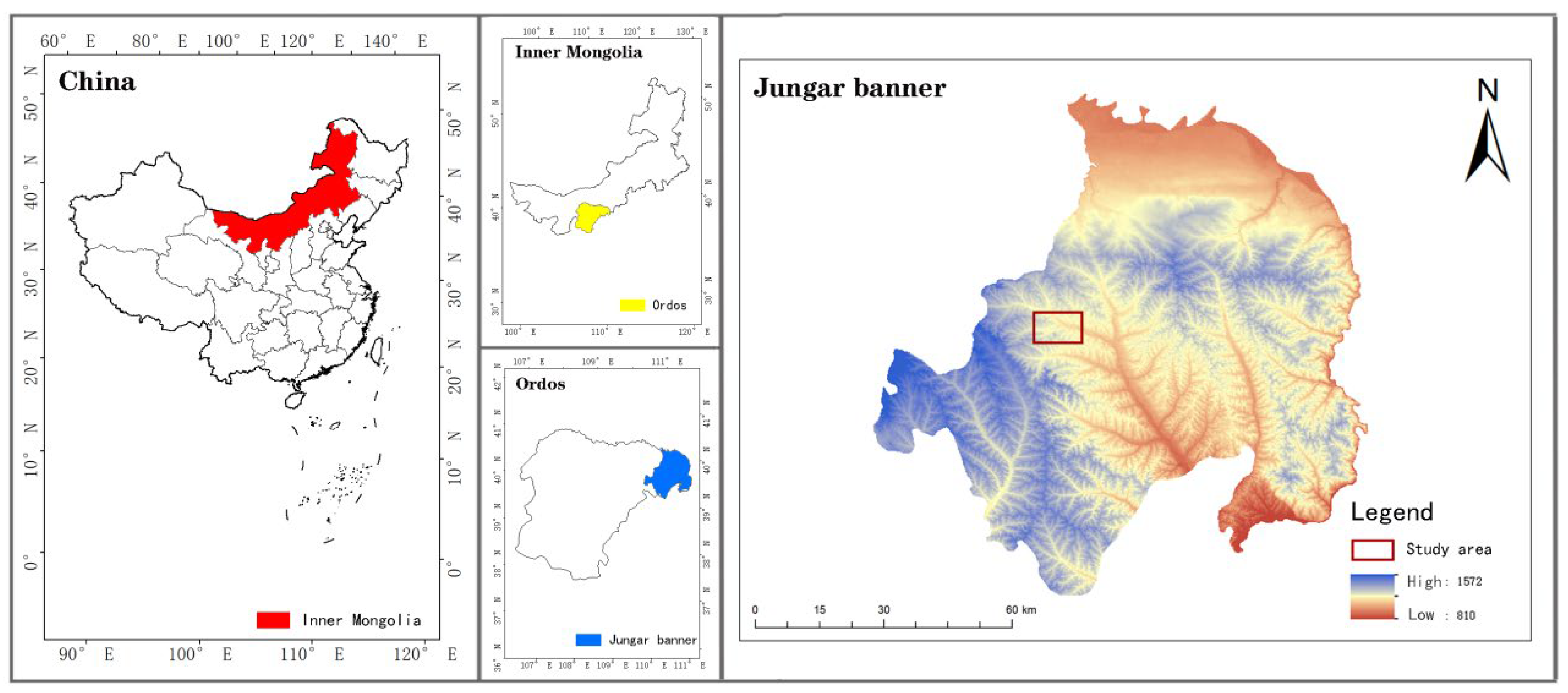
Figure 1. Location of the study area in the Inner Mongolia Autonomous Region, China.
Sustainability 15 13276 g001
Figure 2. Establishment of cells and scanning of micro terrain.
Sustainability 15 13276 g002
Figure 3. Slope erosion.
Sustainability 15 13276 g003
Figure 4. Spatial variation characteristics of soil aggregates. Note: The uppercase letters in the figure represent the difference between different soil layers of the same soil aggregate particle size, and the lowercase letters represent the difference between different soil aggregate particle sizes in the same soil layer.
Sustainability 15 13276 g004
Figure 5. Spatial distribution difference map of soil aggregates in different soil layers before and after rainfall. Note: Different colored areas in the figure indicate the amount of increase or decrease in the number of soil aggregates in the area.
Sustainability 15 13276 g005aSustainability 15 13276 g005b
Figure 6. Soil aggregate content in each soil layer under different erosion intensities. Note: In the figure, B indicates before rainfall, and A indicates after rainfall. The error bars in the figure represent the uncertainty of the values of soil aggregates of different particle sizes.
Sustainability 15 13276 g006aSustainability 15 13276 g006b
Figure 7. Distribution characteristics of SOC before and after rainfall.
Sustainability 15 13276 g007
Figure 8. SOC spatial distribution difference map. Note: The different colored areas in the figure indicate that the amount of soc increased or decreased in that area.
Sustainability 15 13276 g008
Figure 9. SOC content of each soil layer under different erosion intensities. Note: ab represents the difference before and after erosion under the same erosion intensity; different letters mean there is significant difference between the columns.
Sustainability 15 13276 g009
Table 1. Basic physical and chemical properties of soil in the study area.
Soil TypeSoil Composition (%)Bulk Density (g/cm3)Total Nitrogen (g/kg)Total Phosphorus (g/kg)Cation
Exchange Capacity (cmol/kg)
Soil Permeability (mm/min)
ClaySiltSand
Kastanozem5.2251.343.481.640.411.198.260.6–1.2
Table 2. Slope erosion under rainfall.
Rainfall EventErosion Depth(cm)Non-Erosive Zone (Pixels)Total Erosion Area (Pixels)Proportion of Eroded Area (%)
0–11–22–3>3
R115,5751900700915,59469
R2521900017,470521923
R3897300013,748897339
R417,617129253497317,77478
R596108009274961851
R610,83852685791910,96358
R712,3476700637212,41466.1
R89691017,1061066.2
R914,6242420257514,65085
R1045734037112,207465127.6
R116616112010,195662939.4
R1210,952276190693111,24761.9
R133919179014,206394521.7
Table 3. Correlation between SOC and soil aggregates in different soil layers.
Soil Layer/cm >2 mm1–2 mm0.5–1 mm0.25–0.5 mm0.1–0.25 mm
Before Rainfall0–1SOC−0.011−0.1220.3190.0520.358
1–2−0.0540.02−0.349−0.2260.244
2–4−0.136−0.091−0.1950.3830.393
After Rainfall0–1SOC−0.110.0620.1960.1170.493 *
1–2−0.24−0.228−0.435−0.0750.277
2–4−0.255−0.274−0.130.2940.402
Note: * indicates significant correlation at 0.05 level.
Disclaimer/Publisher’s Note: The statements, opinions and data contained in all publications are solely those of the individual author(s) and contributor(s) and not of MDPI and/or the editor(s). MDPI and/or the editor(s) disclaim responsibility for any injury to people or property resulting from any ideas, methods, instructions or products referred to in the content.