Abstract
Renewable energy generation is a manifestation of global economic and societal advancement and serves as a fundamental assurance for humanity’s pursuit of sustainable development. However, recent years have witnessed several instances of high-frequency resonance events in high-voltage direct current (HVDC) transmission systems based on modular multilevel converters (MMC), which have resulted in converter station tripping and significant repercussions on the alternating current (AC) grid. This paper addresses the mid-to-high frequency resonance issues prevalent in flexible DC transmission systems employing modular multilevel converters (MMC-HVDC). To tackle these concerns, an impedance model for MMC’s AC side is established. Utilizing impedance analysis, the essential factors contributing to the negative damping characteristics of MMC are identified as delay and voltage feedforward loops, predominantly causing negative damping in the frequency range exceeding 400 Hz. In response, a suppression strategy is proposed, involving the incorporation of a multi-band stop filter and virtual impedance. This strategy ensures that within the 0–2000 Hz frequency range, only the impedance phase within 230–430 Hz slightly surpasses 90°. Consequently, the phase difference between MMC’s positive-sequence impedance and the AC system impedance is reduced from 222° to 174.7°, thus guaranteeing secure grid operation. Lastly, the accuracy and effectiveness of the theoretical analysis and suppression methodology are verified through the development of an electromagnetic transient model in MATLAB/Simulink, considering delay fluctuations of ±10%.
1. Introduction
In recent years, the rapid development of our country’s economy and society has posed new demands on our power and energy industry. Traditional energy power systems are no longer capable of meeting the electricity needs of modern society [1]. To address these challenges, China has put forward the development goals of carbon peaking and carbon neutrality, emphasizing environmental sustainability and energy efficiency [2]. Hence, emerging renewable energy generation technologies have come to the forefront, serving as crucial measures to address global environmental concerns. In recent years, numerous scholars have conducted research on the subject of renewable energy generation, including [3], who introduced a fuzzy controller for a series-connected Unified Power Quality Conditioner (UPQC) with the integration of a solar photovoltaic system and battery energy storage system. Reference [4] developed an efficient control system for a three-phase cascaded H-bridge multilevel inverter powered by a photovoltaic system. The authors of [5] introduced a mathematical model and control approach for a voltage-source inverter connected to an AC microgrid. The control strategy employed is a state-feedback control with disturbance rejection. With the increasing integration of more renewable energy power plants into the grid, the expanding scale of the power system poses greater challenges to power transmission in terms of both transmission capacity and distance [6]. The superiority of High Voltage Direct Current Transmission (HVDC) technology in cross-boundary power distribution is well established, largely due to its efficient, adaptable power control and the capacity to synchronize differing regional power grids. It plays a pivotal role in devising an interconnected energy network and executing the optimal allocation of renewable energy resources [7]. The realm of direct current transmission technology bifurcates into two segments: the conventional transmission method based on semi-controlled devices and the flexible transmission approach backed by fully controlled devices. The LCC-HVDC, also known as Line Commutation Converter-based HVDC, is reliant on the AC grid voltage during its conversion process. In contrast, the VSC-HVDC, functioning as the Voltage Source Converter-based HVDC, utilizes fully controlled power electronics, notably IGBTs, eliminating dependency on the AC grid voltage during conversion and, thus, avoiding commutation failures. The benefits of VSC-HVDC encompass reduced output voltage harmonics and independent control of both active and reactive power. As a result, it has become increasingly favored in DC transmission projects [8]. The evolution of VSC has seen configurations transition from two-level to three-level and, ultimately, to the MMC setup [9].
In the realm of high-voltage direct current engineering, the topological structure and modulation methods utilized can impose certain restrictions, causing significant drawbacks in two-level and three-level Voltage Source Converters (VSCs) applications. These drawbacks notably encompass issues such as difficulty in achieving voltage balancing, excessive switching losses, and heightened harmonic content present in the output waveform. In contrast, the Modular Multilevel Converter (MMC), which utilizes series-connected sub-modules operating based on sinusoidal principles, effectively addresses these challenges. The sequential activation of the MMC’s sub-modules alleviates voltage balancing issues often observed when multiple Insulated-Gate Bipolar Transistors (IGBTs) are connected in series. This activation approach also decreases the switching frequency of each IGBT, subsequently reducing switching losses. As the converter’s level count increases, its output waveform increasingly resembles an ideal sine wave, exhibiting minimal voltage harmonic content, eliminating the need for supplementary filtering mechanisms [10,11].
The escalating adoption of flexible direct current (DC) transmission technology has inevitably introduced a new array of challenges. In recent years, a number of domestic and international flexible DC grid systems have encountered mid-to-high frequency harmonic oscillations during either their commissioning phase or operational stage [12]. For instance, in the Spain–France interconnection project in 2015, a high-frequency resonance event emerged with a frequency band around 1600 Hz [13]. Subsequently, a resonance phenomenon with a frequency band approximating 1270 Hz was reported in the Luxi back-to-back DC project in 2017 [14]. A year later, during the commissioning phase of the Yu’E back-to-back DC project, a resonance occurrence with frequency bands around 1800 Hz and 700 Hz was observed [15]. Such episodes of high-frequency oscillations can trigger the disconnection of the converter stations, leading to an imbalance between power supply and demand. This imbalance can exert a significant impact on the interconnected alternating current (AC) grid [16].
The existing analysis methods for high-frequency oscillations in flexible DC systems can be categorized into eigenvalue analysis and impedance analysis. Eigenvalue analysis is essentially an extension of the traditional sensitivity criteria applied to the Jacobian matrix. In reference [17], considering multiple factors, the eigenvalue analysis method was employed to analyze high-frequency resonance phenomena in flexible DC transmission systems. Critical determinants for high-frequency resonance modes were pinpointed to be the bandwidth pertaining to the inner current loop of the MMC, as well as the state variables linked to the delay in the control loop. Drawing from the insights of [18], a model for the MMC was constructed utilizing linear time-periodic system theory. It facilitated a comprehensive small-signal stability evaluation of the MMC system under the scope of Floquet theory. Within the context of the MMC-HVDC framework, this technique provides a refined insight into the dynamic interactions among high-frequency harmonics. The impedance analysis method, originally proposed by Middlebrook in 1976, was tailored for stability assessments in DC/DC converters. Advancing this further, Sun employed this method for stability evaluations of single-phase grid-connected inverter systems [19]. In [20], a systematic investigation of the resonance mechanism in MMC-HVDC transmission systems was conducted using a block-impedance modeling approach and harmonic impedance analysis method. The study successfully identified the primary influencing factors for both AC and DC-side resonances in the MMC system. In reference [21], an impedance model for MMC-type AC/DC and DC/DC converters was established. The stability of the cascaded MMC-type converter was analyzed, and a stability enhancement method based on series-connected damping resistors was proposed. The authors of [22], using impedance analysis, determined that the periodic negative damping characteristics of the equivalent impedance of the MMC at high frequencies are caused by control delay. Furthermore, it was found that the oscillation frequency is solely determined by the control delay.
Current strategies aimed at mitigating high-frequency oscillations in flexible DC systems are predominantly divided into active and passive suppression approaches. Passive suppression strategies typically encompass the installation of filtering devices within the AC system for impedance reshaping. Nevertheless, such passive filters carry inherent disadvantages like large footprints and power loss, rendering them unsuitable for application in operational flexible DC transmission systems. Conversely, active suppression strategies strive to optimize the system’s equivalent impedance by altering the control system’s parameters or structure, thus providing enhanced flexibility and control in quelling high-frequency oscillations in flexible DC systems. In [23], a multi-channel signal separator was engineered utilizing cross-decoupling complex filters, and a harmonic current suppressor was fashioned based on the principle of circulating current suppression. However, the complexity of the filtering algorithm intensifies considerably when the harmonic order increases substantially. In [24], high-frequency resonance suppression was realized by incorporating a second-order band-pass filter into the voltage feedforward loop of the controller, an approach adopted in the Luxi Flexible DC Transmission System. The authors of [25] attained high-frequency oscillation suppression by adding a band-stop filter in the voltage feedforward loop, with filter parameters designed for effective oscillation suppression. Furthermore, [26] presents a comparative study on the Luxi Flexible DC Transmission System, evaluating the impacts of introducing a low-pass filter, a band-stop filter, and a nonlinear filter into the voltage feedforward loop. Based on this analysis, three additional damping controller schemes were proposed for harmonic suppression. However, these aforementioned methods, reliant on the parameter tuning of the filtering section within the frequency range where high-frequency oscillation incidents have manifested, may inadvertently transfer the negative damping region to the mid-frequency range, thereby escalating the potential risk of oscillations.
In addressing the challenge above, this research concentrates on the exploration of high-frequency resonance issues in MMC-HVDC systems by adopting a systematic approach involving impedance modeling, stability analysis, formulating suppression strategies, and simulation verification. The study employs a harmonic linearization method to comprehensively consider aspects like the power outer loop, current inner loop, decoupling sections, and delays. Through the creation of an equivalent impedance model designed for high frequencies and considering the correlation between the negative damping band and control delay, we propose a novel active suppression strategy. This strategy entails the incorporation of a multi-band stop filter in conjunction with virtual impedance, followed by an appropriate parameter design process. Finally, to validate the efficacy of this suppression approach, an MMC-HVDC model is developed in MATLAB/Simulink, utilizing the AC parameters from the Luxi Flexible DC Transmission System.
2. Impedance Model
In this section, the MMC positive-sequence impedance model was constructed based on the control system equations of MMC-HVDC. Additionally, following the principle of high-frequency resonance occurrence revealed in [20], the AC system impedance was equivalently represented as a parallel combination of RL and RC. This paper designed AC system impedance parameters to simulate a more pronounced resistive and capacitive behavior. The MMC positive-sequence impedance model and the AC system impedance model were programmatically built in MATLAB.
2.1. MMC-HVDC AC System
The schematic diagram of the equivalent MMC-HVDC AC system is depicted in Figure 1.
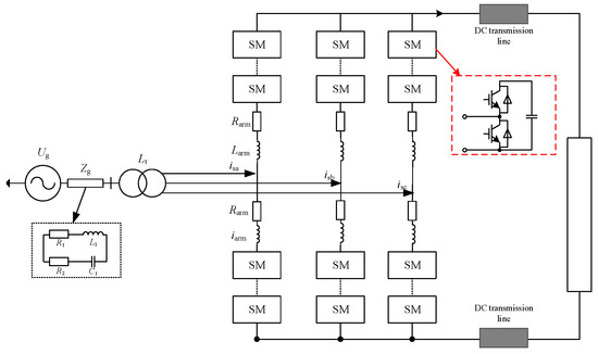
Figure 1.
Equivalent diagram of MMC-HVDC at AC side.
In the illustration provided in Figure 1, Ug signifies the AC grid voltage, while Zg corresponds to the AC grid’s equivalent impedance. Zt is a representation of the cumulative impedance of the converter transformer and MMC bridge arm inductance. More specifically, Zt can be estimated as the aggregate of the transformer’s leakage inductance (Lt) and the bridge arm’s inductance (Larm), which can be expressed as Zt = Leq = Larm/2 + Lt. Considering the negligible influence of MMC’s internal dynamics on the system’s high-frequency stability, this study sets aside the MMC’s internal dynamics. Instead, it focuses on analyzing the MMC’s equivalent impedance characteristics based on the dual-loop control system framework.
As a result, the impedance of the AC system can be expressed by the formula in Equation (1).
2.2. MMC-HVDC Control System
Figure 2 presents a schematic representation of the MMC-HVDC control system. The phase-locked loop (PLL) is employed to extrapolate the grid phase angle, which aids the coordinate transformation stage. The outer loop control of power is tasked with tracking the desired reference signal and subsequently generating the reference signal for the inner current loop. The responsibility of the inner current loop lies in tracking the reference current signal. In collaboration with the decoupling term and voltage feedback loop, it generates the modulation signal. The phenomenon of bridge arm circulating current, a pivotal issue in the investigation of MMC converter stations, warrants attention. The formula encapsulating the bridge arm circulating current, denoted as izj, is expressed as follows:
where iuj represents the upper arm current, and ilj signifies the lower arm current. Hence, the harmonic component within the bridge arm circulating current, referred to as icirj, can be formulated as
where Idc denotes the direct current (DC) side current, and izj is represented as the summation of the harmonic component within the bridge arm and the DC component. This representation is introduced to facilitate analysis and control of the Modular Multilevel Converter (MMC). Notably, the harmonic component only circulates within the MMC and does not influence either the DC or AC sides. As high-frequency resonance occurrences manifest in the AC system grid voltage, the harmonic component within the circulating current does not significantly impact the focus of this study. Consequently, the consideration of internal MMC circulating current is omitted. The circulating current suppression module within the control system, as established in [27], has been proven to be nearly immune to the influence of high-frequency resonance phenomena. Thus, this paper exclusively delves into the exploration of the impact of the power outer loop, current inner loop, voltage feedforward, and phase-locked loop elements on the high-frequency resonance phenomena.
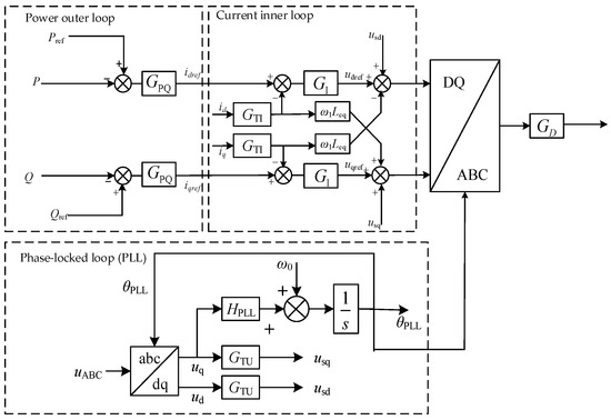
Figure 2.
MMC-HVDC Control System Block Diagram.
Based on previous research on impedance modeling by scholars [21], the harmonic linearized equivalent impedance of the MMC positive sequence can be represented by Equation (3).

Table 1.
The following notations are used to develop the models.
3. High-Frequency Resonance Mechanism and Stability Analysis in MMC-HVDC
This research scrutinizes how various control loops within the MMC control system influence the positive-sequence impedance model of the MMC. The MMC-HVDC system is segmented into two components—the MMC control system and the AC system, drawing on the modularization concept. The resonance mechanism at high frequencies within the MMC-HVDC system is explained based on the impedance criterion.
3.1. High-Frequency Stability Analysis Based on the Equivalent Impedance Model of MMC
In a bid to examine the effects of the power outer loop, current inner loop, phase-locked loop, decoupling term, and other constituents on the high-frequency stability of the MMC equivalent impedance model, an equivalent impedance model of MMC is assembled in a programmatic fashion using MATLAB. This process relies on the parameters detailed in Table 2.
Table 2.
Main parameters of MMC-HVDC transmission system model.
When the power outer loop is neglected, the positive-sequence impedance of the MMC on the AC side is represented by Equation (4).
When the phase-locked loop is neglected, the positive-sequence impedance of the MMC on the AC side is given by Equation (5).
As evident in Figure 3, when the power outer loop is disregarded, an increase in the phase of the MMC’s positive-sequence impedance on the AC side is noticed in the 0–500 Hz frequency range, while a decrease is noted in the 500–1000 Hz range. This indicates that the power outer loop boosts the impedance phase within the 500–1000 Hz frequency range, with minimal impact on frequencies exceeding 1000 Hz. Conversely, when the phase-locked loop is dismissed, the characteristics of the MMC’s positive-sequence impedance on the AC side remain largely stable, rendering the phase-locked loop’s influence on the MMC’s impedance characteristics inconsequential.
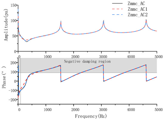
Figure 3.
The MMC impedance characteristics ignoring the power outer loop and PLL.
With the voltage feedback loop omitted, the positive-sequence impedance of the MMC on the AC side can be described using Equation (6).
When the decoupling term in the inner loop is neglected, the positive-sequence impedance of the MMC on the AC side is given by Equation (7).
Figure 4 demonstrates that when the voltage feedback loop is excluded, there is an elevation in the impedance phase of the MMC on the AC side over the 0–1000 Hz frequency range. Within the 0–400 Hz frequency range, the impedance consistently stays within the positive damping region, affirming that the MMC’s stability remains intact. Beyond 400 Hz, the impedance properties of the MMC, in the absence of the voltage feedback loop, deviate from periodicity, tending towards an approximate angle of 90 degrees. This suggests that the voltage feedback loop, coupled with its associated control delay, primarily influences the periodic negative damping features and oscillations prevalent in the mid-to-high frequency domain. Conversely, excluding the decoupling term of the inner loop results in the positive-sequence impedance of the MMC on the AC side remaining fundamentally unchanged, rendering its impact inconsequential.
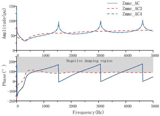
Figure 4.
The MMC impedance characteristics ignoring voltage feedforward and decoupling link.
From Figure 5, it becomes evident that as the delay increases, there is a decrement in the impedance magnitude of the MMC while the phase maintains relative stability. Additionally, a rise in delay coincides with a reduction in the fluctuation period of the MMC impedance characteristics, thus highlighting an inverse correlation between period and delay. In contrast, a decrease in delay leads to the expansion of the negative damping range in MMC impedance characteristics, thereby posing a greater challenge to the suppression of wideband resonance.
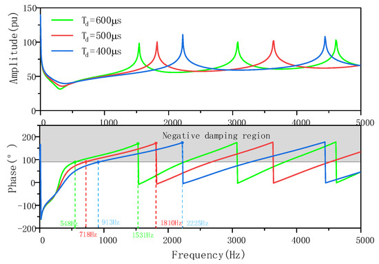
Figure 5.
The MMC impedance characteristics with different delays.
After neglecting the effects of phase-locked loops and decoupling terms, the positive-sequence impedance ZMMC_AC of the MMC on the AC side, as well as the simplified control structure, can be expressed as follows:
According to Equation (6), Figure 6 shows a simplified schematic of the MMC control system
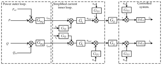
Figure 6.
Simplified schematic diagram of MMC control system.
3.2. Analysis of High-Frequency Resonance Mechanism Based on the Equivalent Impedance Model of MMC
To undertake an impedance-method stability analysis of grid-connected inverters, as discussed in [16], it becomes necessary to segregate the MMC and the AC system into two discrete subsystems at the Point of Common Coupling (PCC). The diagram portrays the small-signal equivalent circuit of the MMC-grid setup. The MMC is symbolized by an optimal current source Is, paralleled with the impedance Zmmc_AC of the converter, whereas the grid system is depicted by an optimal voltage source Ug, in series with the equivalent impedance Zg of the grid system. An equivalent schematic diagram is provided in Figure 7, showcasing the connection between the MMC and the AC system.
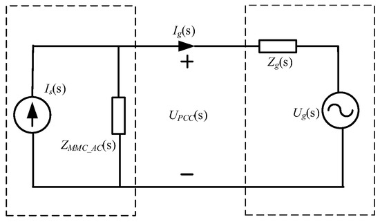
Figure 7.
Equivalent circuit for MMC-connected AC system.
According to the impedance-based criterion, resonance occurs when the absolute values of Zg and Zmmc_AC are equal, and their phase difference exceeds 180°. The resonance frequency corresponds to the frequency at which the amplitude-frequency characteristics of the MMC impedance and the AC system impedance intersect.
As depicted in Figure 8, the intersection point of the MMC’s positive-sequence impedance and the AC system’s impedance is situated around 1200 Hz, with a phase difference approximating 222°. Consistent with the previously outlined criterion, the system is anticipated to encounter oscillations around 1200 Hz. The waveform of the AC system grid-side voltage, along with the Fast Fourier Transform (FFT) analysis results, as shown in Figure 9, corroborates the precision of the analysis.
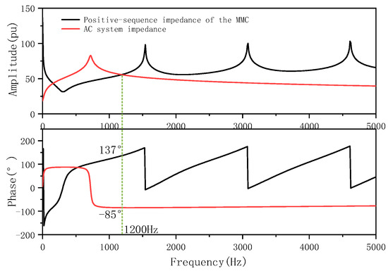
Figure 8.
MMC impedance and AC system impedance.
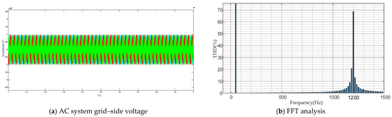
Figure 9.
AC system grid−side voltage and FFT analysis.
4. High-Frequency Resonance Suppression Strategy
4.1. Design of Parameters for Multi-Band Band-Stop Filters
4.1.1. Method for Selecting Multiple Frequency Bands
The typical high-frequency active damping strategy in MMC involves adding a filter in the voltage feedback loop at the oscillation frequency during fault conditions and designing its parameters to reduce the phase characteristic in the negative damping frequency range, thus avoiding a phase difference exceeding 180° with the impedance of the AC system. However, this approach may result in the transfer of the oscillation frequency from the high-frequency range to the mid-frequency range, leading to new instability phenomena. In order to effectively suppress the negative damping characteristics of the MMC in the mid-to-high frequency range, according to [15], the relationship between the negative damping frequency band and the control delay can be represented by the following equation:
Due to the attenuation characteristics of the band-stop filter, the entire negative damping frequency range is divided into multiple frequency bands, with each band’s center frequency set as the center frequency of the corresponding band-stop filter.
The relationships between the parameters can be represented by the following equations, assuming N frequency bands, with bandwidth fT, highest frequency fU, lowest frequency fL, and center frequencies f0:
where i = 1, 2, 3, …, N.
Based on the parameters shown in Table 1 and considering a control delay of 600 μs for the selected engineering example, we can calculate the values as follows:
fU = 1667 Hz; fT = 417 Hz; Negative damping frequency band: .
The negative damping region within 2000 Hz for a control delay of 600 μs, as shown in Figure 5, is indeed (548, 1531). This confirms the accuracy of the analysis.
4.1.2. The Choice and Parameter Design of the Filter
In the context of high-frequency resonance suppression in flexible DC grid-connected systems, there are generally three measures to optimize the impedance characteristics of MMC:
- Optimization of controller parameters or improvement of control strategies.
- Addition of impedance adjustment components.
- Incorporation of filters at various stages.
In this paper, the focus is on discussing high-frequency resonance issues in operational engineering systems. Based on the previous analysis and experimental studies by researchers, adjusting the controller parameters may introduce new stability issues, while implementing improved control strategies can be operationally challenging and may pose a threat to system dynamic response capabilities.
Therefore, the approach chosen is to use additional filters to address high-frequency resonance issues in operational engineering systems. Band-stop filters are selected due to their flexible regulation capabilities and minimal impact on the operating characteristics of the converter.
By employing band-stop filters, the system can effectively mitigate high-frequency resonance problems while maintaining the desired performance and stability of the MMC in the operational environment.
The transfer function of a band-stop filter is given by
where f0 represents the center frequency and denotes the damping coefficient, initially set to .
When the center frequencies of each channel’s band-stop filters are specified, a larger damping coefficient leads to a wider adjustment range. Therefore, it is necessary to further adjust the damping coefficient based on the desired phase margin and adjustment range, refining it to its final value.
This paper is based on the cascaded filter method to design a multi-band active suppression strategy. Therefore, the transfer function of the additional filtering stage is given by
4.2. Multi-Band Resonance Suppression Strategy
4.2.1. Voltage-Feedback-Based Active Suppression Strategy
Based on the previous analysis, the voltage feedback loop and its control delay are the main factors causing the periodic negative damping characteristics in the MMC impedance. Therefore, in this paper, we chose to add a multi-band filter in the voltage feedback loop to suppress mid-to-high frequency resonances.
Let the transfer function of the filter be denoted as Gf1. Figure 10 illustrates the structural diagram of the filter added before the voltage feedback loop.
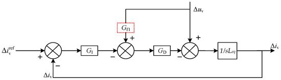
Figure 10.
MMC voltage feedforward stage with filter.
The addition of a filter in the voltage feedback loop will modify Equation (8) to become
Assuming the center frequency f0 of the band-stop filter Gf1 is set to 1200 Hz for targeting the negative damping frequency band around 1200 Hz and considering a damping coefficient ξ of 3, Figure 11 illustrates the MMC impedance characteristics with the addition of the band-stop filter Gf1 in the voltage feedback loop, providing comprehensive filtering effects.
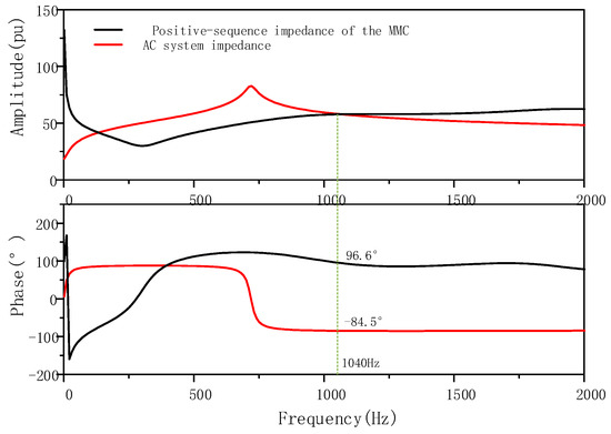
Figure 11.
MMC impedance after voltage feedforward with additional filter and AC system impedance.
Figure 11 reveals an intersection between the MMC’s positive-sequence impedance and the AC system’s impedance at 1040 Hz, displaying a phase difference of 181.1°. The resonance frequency has subsequently migrated from 1200 Hz to 1040 Hz. Consequently, designing a filter solely for the resonant frequency points previously observed could result in the resonance frequency shifting to a lower range, which cannot effectively suppress high-frequency resonances.
4.2.2. Analysis of the High-Frequency Impedance Characteristics of the MMC with the Addition of a Multi-Band Filter
Based on the preceding analysis, the negative damping frequency band for this particular project is situated between 417 and 1667 Hz. For a single-channel scenario, the center frequency is established at 1042 Hz, possessing a channel width of 1250 Hz, with the initial damping coefficient set at 1.2. Following the determination of the center frequency, Figure 12 portrays the equivalent impedance characteristics of the MMC, given varying damping coefficients. It is discernible from the figure that even with the addition of a single-channel band-stop filter, the 400–1800 Hz frequency range continues to reside within the negative damping region.
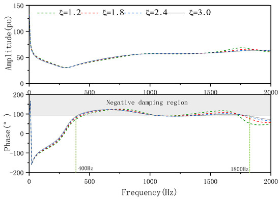
Figure 12.
Comparison of single channel band-stop filters with different damping coefficients.
Figure 13 presents a comparison of different damping coefficients for the three-channel case, where “w” represents the initial damping coefficient for each channel, specifically set to 0.63, 0.38, and 0.63. From the figure, it can be observed that when the damping coefficient exceeds 1.8, the phase of the MMC equivalent impedance in the 340–1100 Hz frequency range still remains in the negative damping region.
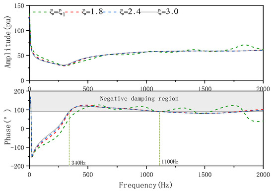
Figure 13.
Comparison of three channels band-stop filters with different damping coefficients.
Figure 11 and Figure 12 demonstrate that a single-channel band-stop filter, irrespective of whether it targets the resonant frequency of 1200 Hz or the center frequency of the negative damping band in the project, cannot wholly obliterate the negative damping attributes of the MMC impedance. Moreover, as illustrated in Figure 13, no notable alteration in the MMC impedance phase is observed once the damping coefficient surpasses 1.8. Consequently, it is infeasible to completely eliminate the negative damping characteristics solely by modulating the damping coefficient or the number of channels.
Due to the constraints of the voltage feedback methodology with an added multi-band trap filter—which only negates the negative damping characteristics brought about by voltage feedback and delay terms—it does not influence the portion incorporating the delay terms in the current inner loop. Therefore, this study proposes to further optimize the MMC impedance characteristics by introducing a virtual impedance component in the inner loop, building upon the addition of a three-channel filter in the voltage feedback loop.
4.2.3. Addition of a Virtual Impedance Component in the Inner Loop of the MMC
Figure 14 illustrates the control structure schematic after adding the virtual impedance component in the inner loop feedback stage of the MMC.
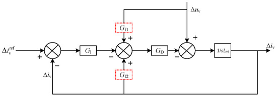
Figure 14.
MMC internal loop with virtual impedance link.
The addition of a virtual impedance component in the current inner loop feedback stage modifies Equation (13) as follows:
As the power outer loop has minimal influence on the phase of the MMC impedance, the addition of the virtual impedance component primarily aims to eliminate the negative damping characteristics introduced by the current inner loop feedback and its associated delay terms. Let Gf2 = k GI, where k represents the gain of the virtual impedance aimed at minimizing the impact of the delay terms introduced by the current inner loop feedback. Figure 15 illustrates a comparison of the adjustment with different gains after adding the virtual impedance.
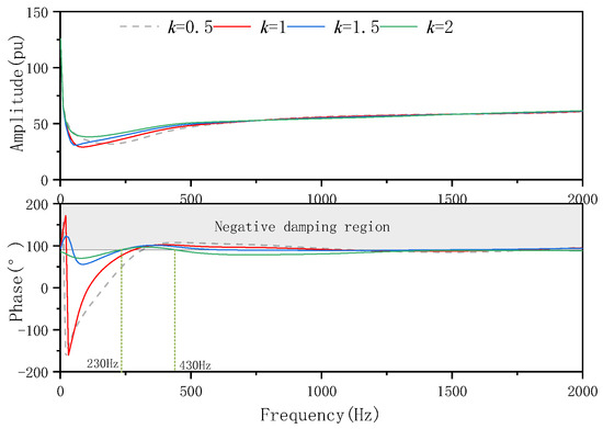
Figure 15.
Comparison of additional virtual impedance regulation at different gains.
From Figure 15, it can be observed that when the gain k is set to 2, hardly any frequency bands in the 0–2000 Hz range exhibit negative damping characteristics. This satisfies the phase margin requirement to a large extent.
The parameter design procedure is illustrated in Figure 16.
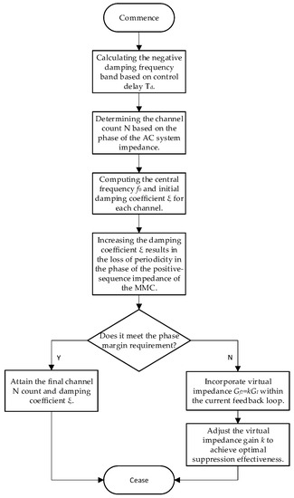
Figure 16.
The schematic of the parameter design process.
5. Simulation Verification
In accordance with the parameter design process depicted in Figure 16, the engineering control delay selected for this study is 600 μs. Consequently, the negative damping frequency band is determined. With a chosen channel count N of 3, the central frequencies are 667 Hz, 1084 Hz, and 1501 Hz, respectively. The damping coefficient for all channels is set at 1.8, while the virtual impedance gain k is designated as 2. The expressions for Gf1 and Gf2 can be simplified as follows:
Substituting Equation (17) into Equation (16) yields the MMC positive-sequence impedance after suppression.
Upon substituting R1 = 8.4 Ω, R2 = 20 Ω, L1 = 0.14 H, and C1 = 0.35 μF into Equation (1), the impedance of the AC system in this study is determined, expressed as Equation (18).
In accordance with the parameters of the China Luxi back-to-back Flexible DC project and the controller parameters enumerated in Table 1, this study constructs an electromagnetic transient simulation model via MATLAB/Simulink. As per the prior analysis, when applying the mitigation measures proposed herein, the MMC equivalent impedance characteristics display negligible negative damping across the 0–2000 Hz frequency range. In the worst-case scenario, the grid AC state becomes resistive and capacitive, and the lowest phase is −90°. Despite this, with the proposed mitigation measures, the phase difference does not surpass 180°. Although reference power step changes are considered a crucial factor in studying power injection capability, their impact on the high-frequency resonance phenomena investigated in this study is practically negligible. This viewpoint has been established in [21], thus justifying the omission of the influence of reference power step changes on the high-frequency resonance phenomenon in this paper. Therefore, the simulation verification performed in this paper accounts for a sensible range of delay fluctuations of ±10%. As the control delay outlined in Table 1 is 600 μs, three representative times—540 μs, 600 μs, and 660 μs—are selected for the simulation verification.
5.1. The Control Loop Delay Is 540 μs
Figure 17a illustrates the comparison of the AC system impedance and the positive-sequence impedance of the MMC with and without the mitigation measures when the control delay is set to 540 μs.
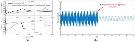
Figure 17.
Impedance analysis and simulation waveform diagram for 540 μs delay. (a) Comparison of the impedance between the MMC and the AC system. (b) Simulation waveform of the grid −side phase A voltage in the AC system.
Referencing Figure 17a, applying the proposed mitigation strategies results in a decrease in the phase difference between the positive-sequence impedance of the MMC and the AC system impedance at 1240 Hz, from an initial 216.5° to a final 168.2°. Additionally, there is virtually no negative damping frequency band in the range of 0–2000 Hz. In the Simulink electromagnetic transient simulation model, the proposed mitigation measures are implemented after 2 s. The waveform of the grid-side phase A voltage after the implementation is shown in Figure 17b.
5.2. The Control Loop Delay Is 600 μs
Figure 18a illustrates the comparison of the AC system impedance and the positive-sequence impedance of the MMC with and without the mitigation measures when the control delay is 600 μs.
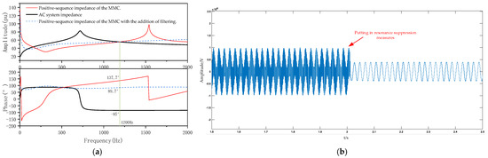
Figure 18.
Impedance analysis and simulation waveform diagram for 600 μs delay. (a) Comparison of the impedance between the MMC and the AC system. (b) Simulation waveform of the grid −side phase A voltage in the AC system.
As depicted in Figure 18a, the implementation of the mitigation strategies proposed herein reduces the phase difference between the positive-sequence impedance of the MMC and the AC system impedance at 1200 Hz, from an original 222.7° down to 174.7°. Additionally, there is virtually no negative damping frequency band in the range of 0–2000 Hz. In the Simulink electromagnetic transient simulation model, the proposed mitigation measures are implemented after 2 s. The waveform of the grid-side phase A voltage after the implementation is shown in Figure 18b.
5.3. The Control Loop Delay Is 660 μs
Figure 19a illustrates the comparison of the AC system impedance and the positive-sequence impedance of the MMC with and without the mitigation measures when the control delay is 660 μs.
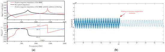
Figure 19.
Impedance analysis and simulation waveform diagram for 660 μs delay. (a) Comparison of the impedance between the MMC and the AC system. (b) Simulation waveform of the grid–side phase A voltage in the AC system.
In Figure 19a, the phase discrepancy between the positive-sequence impedance of the MMC, incorporating the mitigating measures put forth in this study, and the impedance of the AC system at 1160 Hz has been reduced from 228.9° to 175.8°. Furthermore, virtually no negative damping frequency band exists within the 0–2000 Hz range. In the electromagnetic transient simulation model constructed in Simulink, the aforementioned mitigation measures are applied post the 2 s mark. The waveform of the grid-side phase A voltage following this implementation is displayed in Figure 19b.
5.4. Simulation Analysis
Based on the impedance-based criterion, resonance, and instability occur when the phase difference between Zg and Zmmc is greater than 180° at the frequency where their magnitude-frequency characteristics are equal. Analyzing the impedance results as depicted in Figure 17a, Figure 18a and Figure 19a, it can be observed that the phase difference between the MMC positive-sequence impedance and the AC system impedance exceeds 180°, rendering the AC system capacitive and negatively phased. Meanwhile, due to the influence of the voltage feedforward and delay components, the phase of the MMC positive-sequence impedance exceeds 90°, exhibiting a negative damping characteristic. Thus, the high-frequency resonance is a manifestation of the interplay between the capacitive nature of the AC system and the delay component in the control system.
From Figure 17a, Figure 18a and Figure 19a, it can be observed that appropriately increasing the control delay causes the intersection point of the MMC positive-sequence impedance and the AC system impedance magnitude-frequency characteristics to shift towards lower frequencies. Within a certain range of delay fluctuations, upon implementing the suppression measures proposed in this study, the frequency-phase difference at the intersection point of the MMC positive-sequence impedance and the AC system impedance magnitude-frequency characteristics transitions from being greater than 180° to being less than 180°, while maintaining a certain degree of phase margin. However, from Figure 19a, it can be observed that even after implementing the suppression measures, the phase of the MMC positive-sequence impedance at the intersection point remains greater than 90°. Therefore, the high-frequency resonance suppression measures proposed in this study can reduce the impedance phase of the MMC positive-sequence impedance to below 90° in most frequency ranges. However, in cases of more severe AC system capacitance, there still exists a risk of resonance.
According to the simulated waveforms shown in Figure 17b, Figure 18b and Figure 19b, the resonant amplitude of the grid-side voltage decreases with the increase in the system control delay, so the resonance risk can be mitigated by appropriately increasing the control delay. Putting the suppression measures designed in this paper at 2 s, the resonance voltage amplitude is quickly reduced to the rated value under certain delay fluctuations, and the system returns to stable operation. Therefore, this paper analyzes the impedance model of each link in the MMC control system and finds that the most important link for high-frequency resonance is the voltage feedforward and control delay, and the idea of attaching a multi-band band-stop filter and virtual impedance link to offset the delay in the system in this link is feasible.
6. Conclusions
This study formulates an impedance model for the AC facet of the MMC-HVDC system, dissecting the critical elements driving high-frequency resonance in the MMC and streamlining the impedance model of the MMC controller. A resonance mitigation strategy is then suggested, built upon the simplified model. This strategy recommends the utilization of multi-band stop filters and supplementary virtual impedance to enhance the impedance characteristics of the system. The validity and efficacy of this approach are corroborated via theoretical scrutiny and simulated outcomes, culminating in the underlined conclusions:
- (1)
- The control delay, power outer loop, current inner loop, and voltage feedforward loop bear significance in the high-frequency impedance modeling of the MMC. Among these, the voltage feedforward loop and the associated control delay play a pivotal role as the primary factors contributing to the occurrence of periodic negative damping characteristics and resonance phenomena in a frequency range exceeding 400 Hz.
- (2)
- Building upon the framework of the China Luxi back-to-back Flexible DC Transmission Project, this paper introduces a strategy to mitigate the influence of delay components within the positive-sequence impedance of the Modular Multilevel Converter (MMC). In order to achieve this, the proposed approach involves the addition of a 3-channel band-stop filter within the voltage feedforward loop and the incorporation of virtual impedance within the current feedback loop. These enhancements are accompanied by meticulous parameter design.
- (3)
- Applying the parameter design method proposed in this paper, it is feasible to decrease the phase difference between the positive-sequence impedance of the Modular Multilevel Converter (MMC) and the impedance of the AC system at 1200 Hz from 222.7° to 174.7°. Furthermore, this enhancement ensures the stable operation of the power grid even under specific delay fluctuations.
The investigation conducted in this study reveals that active suppression alone is insufficient to completely eliminate the negative damping characteristics of the positive-sequence impedance of the Modular Multilevel Converter (MMC) across the entire frequency spectrum. In future research, it could be valuable to explore the development of a high-frequency resonance suppression strategy for MMC by combining active suppression strategies with passive filtering techniques.
Author Contributions
Conceptualization, T.C. and H.W.; methodology, T.C.; software, T.C.; validation, T.C. and W.W.; formal analysis, investigation, resources, T.C.; data curation, W.W.; writing—original draft preparation, T.C.; writing—review and editing, W.W.; visualization, T.C.; supervision, H.W.; project administration, W.W.; funding acquisition, W.W. All authors have read and agreed to the published version of the manuscript.
Funding
This research was funded by the National Natural Science Foundation of China (grant numbers 52267005 and 52067020) and the Major Science and Technology Special Project of Xinjiang Uygur Autonomous Region Science and Technology Department (grant number 2022A01004).
Institutional Review Board Statement
Not applicable.
Informed Consent Statement
Not applicable.
Data Availability Statement
Not applicable.
Acknowledgments
The authors are sincerely thankful to the Editor, the Associate Editor, and anonymous reviewers for their helpful comments and suggestions on the earlier version of the manuscript.
Conflicts of Interest
The authors declare no conflict of interest.
References
- Chen, Q.; Li, Q.; Wu, J.; He, J.; Mao, C.; Li, Z.; Yang, B. State Monitoring and Fault Diagnosis of HVDC System via KNN Algorithm with Knowledge Graph: A Practical China Power Grid Case. Sustainability 2023, 15, 3717. [Google Scholar] [CrossRef]
- Mohamed, N.; Ahmed, E.; Tamou, N. Improving Low-Voltage Ride-Through Capability of a Multimegawatt DFIG Based Wind Turbine under Grid Faults. Prot. Control Mod. Power Syst. 2020, 5, 370–382. [Google Scholar]
- Srilakshmi, K.; Sujatha, C.N.; Balachandran, P.K.; Mihet-Popa, L.; Kumar, N.U. Optimal Design of an Artificial Intelligence Controller for Solar-Battery Integrated UPQC in Three Phase Distribution Networks. Sustainability 2022, 14, 13992. [Google Scholar] [CrossRef]
- Khemili, F.Z.; Bouhali, O.; Lefouili, M.; Chaib, L.; El-Fergany, A.A.; Agwa, A.M. Design of Cascaded Multilevel Inverter and Enhanced MPPT Method for Large-Scale Photovoltaic System Integration. Sustainability 2023, 15, 9633. [Google Scholar] [CrossRef]
- Khan, H.S.; Memon, A.Y. Active and Reactive Power Control of the Voltage Source Inverter in an AC Microgrid. Sustainability 2023, 15, 1621. [Google Scholar] [CrossRef]
- Mehdi, T.; Mehdi, N. Human Reliability Analysis in Maintenance Team of Power Transmission System Protection. Prot. Control Mod. Power Syst. 2020, 5, 270–282. [Google Scholar]
- Xu, Z.; Chen, H. Review and Applications of VSC HVDC. High Volt. Eng. 2007, 33, 1–10. [Google Scholar] [CrossRef]
- Li, Y. Research on Stability Analysis and Control Method of VSC-HVDC System Based on Impedance Method. Ph.D. Thesis, Wuhan University, Wuhan, China, 2020. [Google Scholar]
- Yao, L.; Wu, Q.; Wang, Z.; Li, Y.; Lu, Z. Pattern Analysis of Future HVDC Grid Development. Proc. CSEE 2014, 34, 6007–6020. [Google Scholar] [CrossRef]
- Guan, M. Control Strategies for Modular Multilevel Converter Based HVDC Transmission System. Ph.D. Thesis, Zhejiang University, Hangzhou, China, 2013. [Google Scholar]
- Tu, Q. Research on Several Issues in Modular Multilevel Converter Based HVDC. Ph.D. Thesis, Zhejiang University, Hangzhou, China, 2013. [Google Scholar]
- Yin, C.; Xie, X.; Liu, H.; Wang, X.; Wang, Z.; Chi, Y. Analysis and Control of the Oscillation Phenomenon in VSC-HVDC Transmission System. Power Syst. Technol. 2018, 42, 1117–1123. [Google Scholar] [CrossRef]
- Saad, H.; Fillion, Y.; Deschanvres, S.; Vernay, Y.; Dennetiere, S. On resonances and harmonics in HVDC-MMC station connected to AC Grid. IEEE Trans. Power Deliv. 2017, 32, 1565–1573. [Google Scholar] [CrossRef]
- Zou, C.; Rao, H.; Xu, S.; Li, Y.; Li, W.; Chen, J.; Zhao, X.; Yang, Y.; Lei, B. Analysis of Resonance Between a VSC-HVDC Converter and the AC Grid. IEEE Trans. Power Electron. 2018, 33, 10157–10168. [Google Scholar] [CrossRef]
- Guo, X.; Liu, B.; Mei, H.; Liu, J.; Yu, H.; Cao, F. Analysis and Suppression of Resonance Between AC and DC Systems in Chongqing-Hubei Back-to-Back HVDC Project of China. Autom. Electr. Power Syst. 2020, 44, 157–164. [Google Scholar]
- Yang, S.; Liu, K.; Qin, L.; Zhou, T.; Zhu, S.; Hong, C. Research Progress of High Frequency Oscillation in MMC-HVDC. High Volt. Eng. 2021, 47, 3485–3496. [Google Scholar] [CrossRef]
- Li, Y.; He, Z.; Pang, H.; Yang, Y.; Ji, K.; Huang, W. High Frequency Stability Analysis and Suppression Strategy of MMC-HVDC Systems (Part I): Stability Analysis. Proc. CSEE 2021, 41, 5842–5856. [Google Scholar] [CrossRef]
- Ruan, B.; Zheng, X.; Zhu, S.; Le, J. Small-signal stability analysis of modular multilevel converters based on Floquet theory. Power Syst. Prot. Control 2021, 49, 1–8. [Google Scholar] [CrossRef]
- Sun, J. Impedance-Based Stability Criterion for Grid-Connected Inverters. IEEE Trans. Power Electron. 2011, 26, 3075–3078. [Google Scholar] [CrossRef]
- Dai, F.; Zeng, D.; Liu, S.; Wang, G. A Practical Impedance Modeling Method of MMC-HVDC Transmission System for Medium- and High-Frequency Resonance Analysis. Electr. Power Syst. Res. 2022, 212, 108636. [Google Scholar] [CrossRef]
- Sun, W.; Xia, X.; Liu, G.; Lu, X.; Yang, R.; Ma, H.; Wang, Z. MMC-based cascaded converter impedance model and stability analysis. Power Syst. Prot. Control 2023, 51, 117–127. [Google Scholar] [CrossRef]
- Huang, T.; Yang, F.; Zhang, D.; Chen, X. High-Frequency Stability Analysis and Impedance Optimization for an MMC-HVDC Integrated System Considering Delay Effects. IEEE J. Emerg. Sel. Top. Circuits Syst. 2022, 12, 59–72. [Google Scholar] [CrossRef]
- Shi, J.; Liu, J.; Xu, J.; Pan, C.; Shi, S. Suppression strategy for an MMC grid-side background harmonic current based on a multi-channel signal separator. Power Syst. Prot. Control 2021, 49, 106–113. [Google Scholar] [CrossRef]
- Guo, Q.; Guo, H.; Huang, L. Effect of Grid Voltage Feedforward on VSC-HVDC Stability in Weak Power Grid. Autom. Electr. Power Syst. 2018, 42, 139–144. [Google Scholar]
- Du, D.; Guo, C.; Jia, X.; Zhao, C.; Hu, Y. Suppression Strategy for High Frequency Resonance of Modular Multilevel Converter Based on Additional Band-Stop Filter. Trans. China Electrotech. Soc. 2021, 36, 1516–1525. [Google Scholar] [CrossRef]
- Chen, W.; Wang, J.; Ye, Y.; Liu, Y.; Feng, J.; Fu, C. Additional Damping Suppression Measures for Medium- and High-frequency Resonance on AC Side of MMC-HVDC Transmission System. Autom. Electr. Power Syst. 2021, 45, 151–161. [Google Scholar]
- Li, Y.; An, T.; Zhang, D.; Pei, X.; Ji, K.; Tang, G. Analysis and Suppression Control of High Frequency Resonance for MMC-HVDC System. IEEE Trans. Power Deliv. 2021, 36, 3867–3881. [Google Scholar] [CrossRef]
Disclaimer/Publisher’s Note: The statements, opinions and data contained in all publications are solely those of the individual author(s) and contributor(s) and not of MDPI and/or the editor(s). MDPI and/or the editor(s) disclaim responsibility for any injury to people or property resulting from any ideas, methods, instructions or products referred to in the content. |
© 2023 by the authors. Licensee MDPI, Basel, Switzerland. This article is an open access article distributed under the terms and conditions of the Creative Commons Attribution (CC BY) license (https://creativecommons.org/licenses/by/4.0/).