Article

Research on Design and Control Strategy of Novel Independent Metering System

1
Hebei Provincial Key Laboratory of Heavy Machinery Fluid Power Transmission and Control, Yanshan University, Qinhuangdao 066004, China
2
Key Laboratory of Advanced Forging & Stamping Technology and Science, Yanshan University, Qinhuangdao 066004, China
3
Hebei Key Laboratory of Special Delivery Equipment, Yanshan University, Qinhuangdao 066004, China
*
Author to whom correspondence should be addressed.
Sustainability 2023, 15(18), 13359; https://doi.org/10.3390/su151813359
Submission received: 26 July 2023 / Revised: 31 August 2023 / Accepted: 1 September 2023 / Published: 6 September 2023

Abstract

:
The independent metering system used in the combination of traditional cartridge proportional valves employs an excessive number of components, which increases the complexity of the control strategy. To address this problem, a novel independent metering system based on pilot hydraulic control was developed. Following the pressure and flow requirements, the structure and valve body size of the two spools were designed. The effect of the parameter change in the control valve on the dynamic response characteristics of the main spool was investigated by simulation. A control strategy was developed based on load force direction prediction and two-chamber pressure switching to verify the feasibility of working mode switching during load direction change. As indicated by the results, compared with the mode switching control strategy of the traditional independent metering system, the proposed control strategy could effectively reduce the number of mode switching and ensure the continuity of the actuator operation. Compared with the traditional load-sensitive valve control system, the proposed pilot-controlled independent metering system achieved an average energy-saving efficiency of 47.27%. This study provides technical reference for the low energy consumption, high efficiency, and sustainable development of hydraulic systems.

1. Introduction

Hydraulic transmission technology has taken on critical significance in economic development, especially in construction machinery and other infrastructure equipment. However, the characteristics of low efficiency in exchange for outstanding advantages have been reported as the application limitations of hydraulic technology. The disadvantages of hydraulic transmission systems are as follows: (1) Large power loss and low transmission efficiency in the transmission process. (2) High energy consumption and serious heat generation. (3) High cost and large carbon emissions, which is contrary to the world trend of energy-saving, green, and sustainable development. Accordingly, the energy-saving technology of the hydraulic system should be studied to reduce energy consumption, decrease heat generation, and optimize the environment. The goals of energy-saving, low carbon, emission reduction, and environmental friendliness have been achieved to satisfy the strategic requirements of the sustainable development of hydraulic systems. Energy-saving technologies (e.g., load-sensing control, secondary regulation, and accumulator potential energy recovery) have been well applied to the hydraulic system, whereby they have been subjected to certain limitations and have not fundamentally changed the valve orifice throttling loss arising from the simultaneous throttling of the inlet and outlet.
The traditional hydraulic valve control system couples and adjusts the throttle area of the inlet and outlet through the displacement of the valve spool, with a single degree of control freedom. It cannot independently control the inlet and outlet under practical working conditions, resulting in excess throttle loss and an inability to achieve the flow regeneration function, such that low system efficiency is achieved. The independent metering system breaks the limitation of the traditional valve control system linkage adjustment of the throttle area of the inlet and outlet valve ports. The pressure and flow of the two chambers of the actuator were no longer coupled with the adjustment of the opening of the inlet and outlet valve ports separately, such that excess throttle loss can be reduced under low back pressure conditions. The combination of multiple valves to achieve multiple functions can increase the control freedom and significantly enhance the energy-saving and controllability of the traditional valve control system. Figure 1 presents the principle of the traditional valve control system and independent metering system. Ps is the high-pressure port, and P0 is the low-pressure port. xv represents the displacement of the traditional valve core, x1 represents the displacement of the inlet throttle valve core, and x2 represents the displacement of the outlet throttle valve core.
The research on the independent metering system by domestic and foreign researchers has placed a major focus on the hydraulic system and different control strategies of the combination design of multiple hydraulic valves to improve the energy-saving characteristics of the system.

1.1. System Design

For designing the independent metering system, Huang et al. [1] proposed using two 3/3 proportional valves to form an independent metering system to study the rotation of the excavator, improve the dynamic characteristics of the system, and verify the reliability of the system through experiments. Liu et al. [2] used five 2/2 proportional valves and two 3/2 directional valves to form an independent metering system. Taking the excavator as the carrier, it was compared with the traditional load-sensitive hydraulic system to prove the energy-saving performance of the proposed independent metering system. Abuowda et al. [3] designed a stepped rotary flow control valve and proposed the use of four flow control valves to form an independent metering system, and investigated its system characteristics. Liu et al. [4] proposed the independent metering system composed of two servo valves and applied it to the electro-hydraulic steering system (EHSS). The energy saving and response characteristics of the system were proved by experimental research. Nguyen et al. [5] investigated the use of three 2/2 proportional valves and a 4/3 directional valve to build an independent metering system. Taking the boom of the excavator as the carrier, compared with the traditional independent metering system, its energy saving can be improved by 6.5%. Chen et al. [6] used two 4/3 servo valves to form an independent metering system. Compared with the traditional valve-controlled hydraulic system, the energy saving and control reliability of the proposed system were proved by experiments. Ahamad et al. [7] proposed three 2/2 proportional valves and a 4/3 directional valve to develop an independent metering system. Additionally, they employed a variable pump to supply oil to the system. The energy saving and effectiveness of the proposed system were proved through the simulation and comparison of the traditional four-valve spool independent metering system. Using four high-speed on-off valves as pilot valves, Zhong et al. [8] drove the design of two 3/3 main valves to form an independent metering system and conduct research. As indicated by the result of the experimental research, the proposed system is capable of maintaining a good dynamic performance and robustness. With two 4/3 proportional valves as the pilot stage, Zhong et al. [9] drove the structure design of two 3/3 main valves to achieve the independent metering system of pilot hydraulic control. Next, they investigated its pressure and flow compound control characteristics. Liu et al. [10] used pressure compensation to perform valve front compensation on the designed independent metering system. Theoretical analysis showed that valve front compensation can prevent a cavitation phenomenon. Choi et al. [11] utilized four 2/2 proportional valves to achieve an independent metering system through combination, and compared it with the traditional valve control systems. Simulation analysis showed the energy-saving performance of the system. Using five 2/2 proportional valves, Hu et al. [12] achieved an independent metering system. Compared with the traditional valve control system, it can realize the flow regeneration function and improve the energy-saving of the system.

1.2. Control Strategy

For the control strategy of the independent metering system, Shi et al. [13] proposed a control strategy based on mode switching that combines speed and position, where the independent metering system (comprising two 4/3 proportional valves) served as the research object. Through experimental research on the excavator arm and stick, Ding et al. [14] designed strategies for multi-mode switching and multivariable controllers to adapt to time-varying and uncertain load characteristics, and verified the effectiveness of the proposed control strategy and the energy-saving performance of the independent metering system through an excavator experimental platform. Koivumäki et al. [15] introduced the independent metering system (comprising two 4/3 proportional valves) into the three-degree-of-freedom manipulator, and proposed the strategy of the separate control of pressure and flow. The reliability of the proposed strategy was confirmed through experiments. The energy consumption of the system was reduced by 45%, compared with the traditional valve control system. Liu et al. [16] designed four control strategies for the independent metering system, and compared the traditional valve control system to prove the energy saving and stability of the independent metering system. Bao et al. [17] proposed a fuzzy linear self-anti-interference control strategy and then introduced it into an independent metering system. Experimental research was conducted using a concrete pump truck as a carrier, proving that the proposed strategy can improve the speed and stability of system response. Lyu et al. [18] proposed a high-performance adaptive robust control strategy and proved the feasibility of the proposed control strategy and the accuracy of system response through experiments, where the independent metering system comprising four 2/2 proportional valves and two 2/2 directional valves served as the research object. Abuowda et al. [19] proposed a new control strategy to realize the switching between different modes by taking the independent metering system composed of four-stepped rotary valves as the research object. Nguyen et al. [20] combined pump control with an independent metering system, adopted the control strategy of speed feedforward and position feedback, and designed the switching mode of the system to increase the accuracy and energy-saving of the system response. Su et al. [21] proposed a data-based flow prediction method, where the independent metering system composed of four 2/2 proportional valves served as the research object. They also compared eight different data-based estimation models to provide a reference for the high-precision flow prediction of hydraulic valves. Lyu et al. [22] proposed to combine the pump control with the independent metering system, control the pump in a speed feedforward manner, and apply high-performance adaptive robust control to the closed-loop controller. The position-tracking accuracy of the system was proven through experiments. Li et al. [23] took the traditional four-valve spool independent metering system as the research object, proposed a nonlinear valve flow model for the valve dead zone problem, compensated the dead zone through the static inverse function, and increased the control accuracy of the system using adaptive robust control strategy. Hu et al. [24] yielded a variable universe fuzzy control algorithm, which was introduced into the two-valve spool structure of the independent metering control system. The excavator served as the carrier to compare the system response speed and stability before and after optimization. Ding et al. [25] proposed an active sensor fault-tolerant controller (SFTC) for an independent metering system while designing a disturbance-free switching strategy for potential tracking. The feasibility of the proposed SFTC system was verified on a 2-ton excavator experimental platform.
In general, the traditional independent metering system primarily employs multiple cartridge proportional valves for independent control of the pressure and flow of the two chambers of the hydraulic actuator. However, with the increase of the number of cartridge proportional valves applied, the following problems will be triggered. (1) The valve body becomes complex, and it is prone to local pressure loss. (2) The excessive use of hydraulic components can lead to multiple fault points and difficulty in troubleshooting. (3) The layout is complex and excessively dependent on the characteristics of proportional cartridge valves in the control process. (4) The control strategy becomes more complex.
Therefore, this study was aimed at addressing the drawbacks of traditional cartridge-independent metering valves and proposing an independent metering valve based on pilot hydraulic control. The proposed valve can show the following advantages: (1) A reasonable layout, which can achieve the compact design of the valve spool and valve body structure. (2) Less use of hydraulic components, strong interchangeability, high reliability, and fewer fault points. (3) Adopting pilot hydraulic control driving mode, such that it is enabled to satisfy the requirement of different working conditions. In a traditional independent metering system, different pressure and flow compound control methods should be designed based on varying load conditions. In multi-mode switching control strategies, the number of switches increases with the conversion of working conditions, such that the control strategy turns out to be complex. Therefore, a control strategy based on load force direction prediction and two-chamber pressure switching was developed to satisfy the requirement of different working conditions, decrease the number of mode switching, and improve the continuity of the hydraulic actuator operation.
The main contributions of this study can be summarized as follows:
(1)
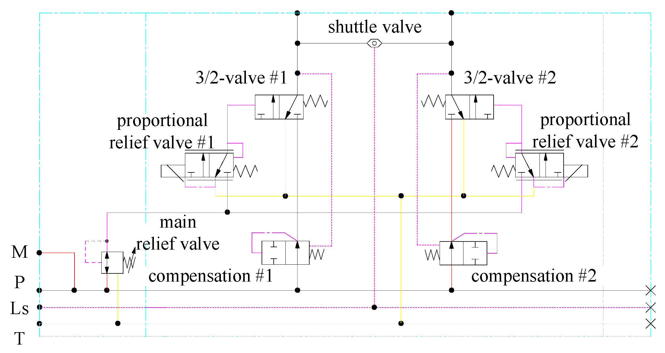
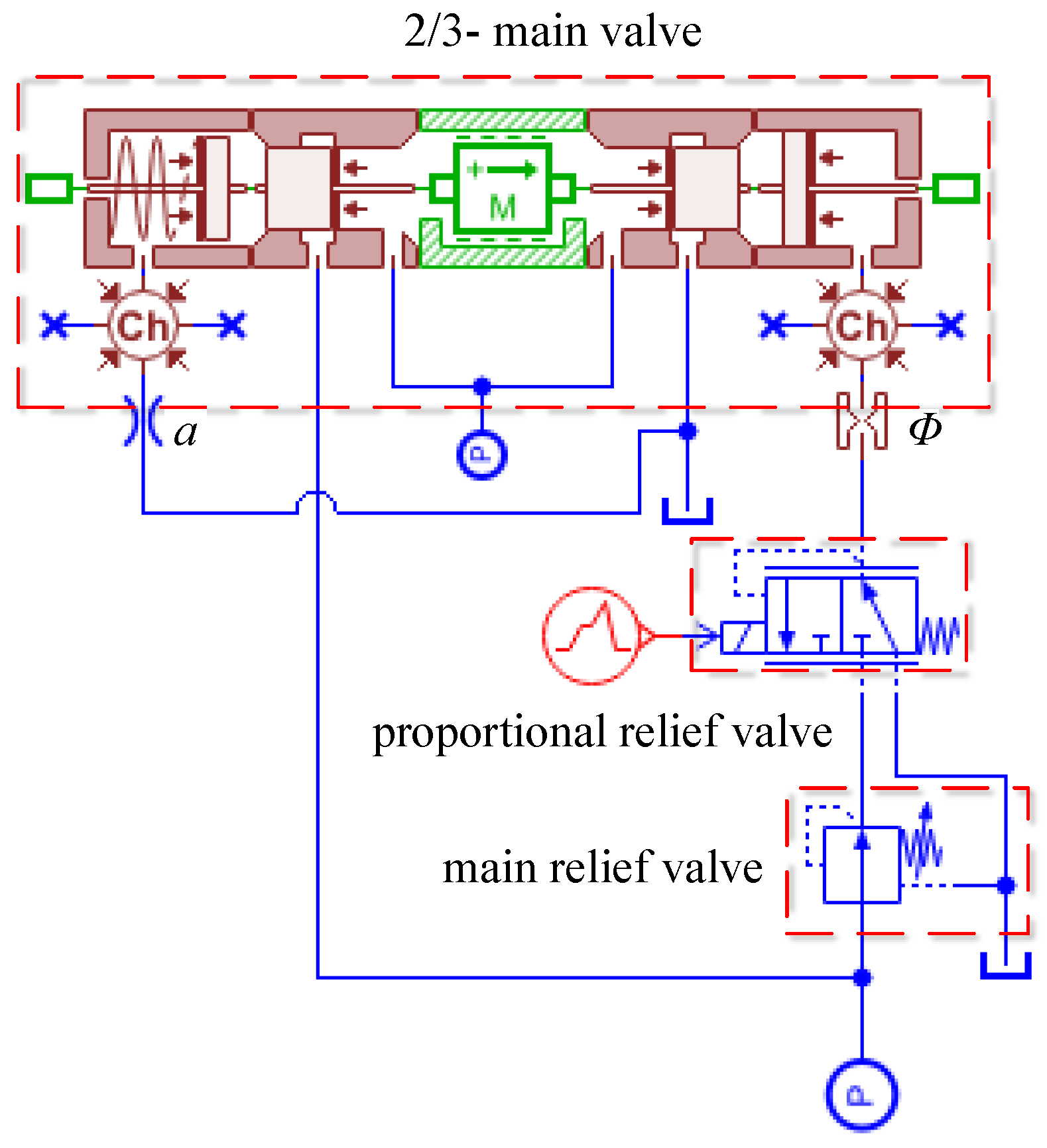
The disadvantages of the independent metering composed of the traditional cartridge proportional valve were investigated. Moreover, a scheme of the independent metering valve was proposed based on pilot hydraulic control, and its working principle was explained. Combined with the design requirements of pressure and flow, the two-valve spool structure and valve body size were designed, the main valve spool simulation model was built, and the parameters affecting the dynamic response characteristics of the main spool were investigated and then optimized.
(2)
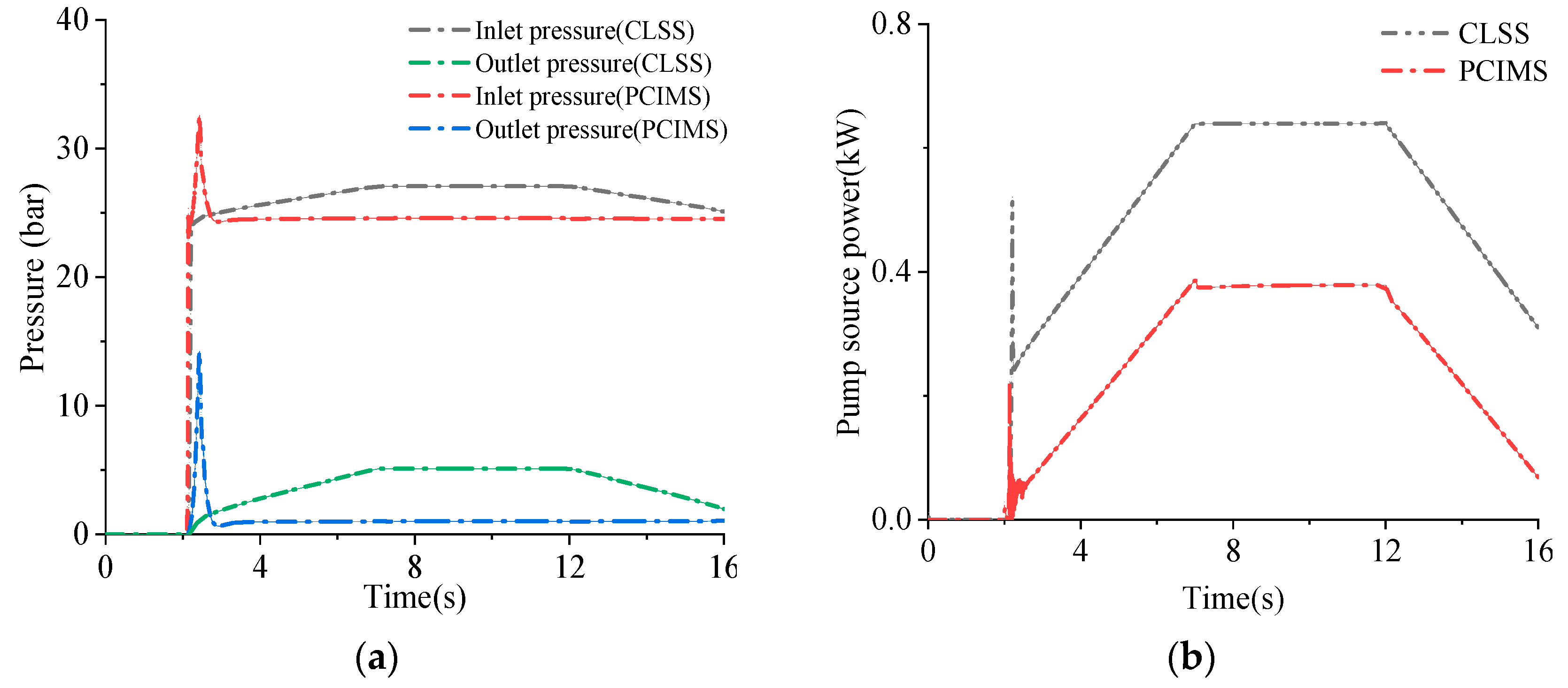
The simulation model of the independent metering system based on pilot hydraulic control and the traditional valve control system was built, and the two-chamber pressure of the hydraulic actuator and pump source power variation characteristics under constant load conditions were investigated to prove the feasibility and energy-saving of the proposed scheme. A control strategy was proposed following the load force direction prediction and two-chamber pressure switching, which was applied to the independent metering system following pilot hydraulic control. The effectiveness and reliability of the proposed control strategy were verified through simulation.
The structure of this study is presented as follows. In Section 2, the principle, control strategy, and structure design of the independent metering valve based on pilot hydraulic control are proposed. In Section 3, the effect of key parameter changes in the main valve spool on the dynamic characteristics of the main valve are analyzed. Moreover, the load force direction prediction and the two-chamber pressure switching control strategy are applied to the independent metering system based on pilot hydraulic control. Lastly, the energy-saving of the system and the effectiveness of the proposed control strategy are validated through simulation and summarized in Section 4.

2. Introduction of New Independent Metering System

2.1. The Principle of New Control Valve

A pre-valve compensation layout based on pilot hydraulic control was proposed following the principle of hydromechanical pressure compensation and the working principle of the independent metering system. The independent metering system of the hydromechanical pressure compensation was composed of multiple hydraulic valves, which comprised the main pressure relief valve, two pressure compensation valves, two proportional pressure relief valves, shuttle valves, two 3/2 valve spools, as well as valve bodies. The main pressure relief valve reduced the pump source pressure by one stage, such that pressure fluctuations were reduced, and it was transmitted to two proportional pressure relief valves. Two proportional relief valves controlled the displacement of the main valve spool by regulating the correlation between pressure and spring. Two pressure compensation valves maintained a constant pressure difference between the inlet and outlet of the main valve spool, such that a linear relationship between the opening degree of the main valve and the flow rate was ensured. The shuttle valve could feedback the maximum working pressure in the two chambers of the actuator to the Ls end of the load-sensitive pump. As a result, the load-sensitive pump output the required flow rate to the system. Figure 2 illustrates the principle of the independent metering valve based on pilot hydraulic control, M represents the pressure measuring port, P is the high-pressure port, Ls is the load-sensitive port, and T is the low-pressure port, which was connected with the hydraulic tank. The red line represents the high-pressure oil circuit, the magenta line represents the control oil circuit, the yellow line represents the low-pressure oil circuit, and the cyan line represents the hydraulic components.
The working principle is elucidated as follows. When the A port entered the oil and the B port returned the oil, the main pressure relief valve reduced the pressure of the pump source by one stage while transmitting the pressure to the proportional relief valve #1; the proportional relief valve #1 transferred the secondary pressure reduction to the 3/2 valve #1, and compressed the spring of the 3/2 valve #1 to produce displacement, such that the high-pressure flow flowed into the rodless cavity of the hydraulic cylinder, and the pressure compensation valve #1 compensated for the inlet and outlet of the 3/2 valve #1. The low-pressure oil in the rod cavity of the hydraulic cylinder was directly returned to the oil through the 3/2 valve #2. In the above-mentioned process, the pressure compensation valve #2 and the proportional relief valve #2 did not work. The shuttle valve introduced the high pressure of the rodless cavity of the hydraulic cylinder into the Ls end of the valve group, and its working principle is depicted in Figure 3a.
When the B port entered the oil and the A port returned the oil, the main pressure relief valve reduced the pressure of the pump source by one stage while transmitting the pressure to the proportional relief valve #2; the proportional relief valve #2 transferred the secondary pressure reduction to the 3/2 valve #2 and compressed the spring of the 3/2 valve #2 to produce displacement. Thus, the high-pressure flow flowed into the rod cavity of the hydraulic cylinder, and the pressure compensation valve #2 compensated for the inlet and outlet of the 3/2 valve #2. The low-pressure oil in the rodless cavity of the hydraulic cylinder was directly returned to the oil through the 3/2 valve #1. In the above-described process, the pressure compensation valve #1 and the proportional relief valve #1 did not work. The shuttle valve introduced the high pressure of the rodless cavity of the hydraulic cylinder into the Ls end of the valve group, and its working principle is depicted in Figure 3b.
Compared with the independent metering system formed by the traditional cartridge proportional valve combination, the advantages of the novel independent metering valve based on pilot hydraulic control are presented as follows. (1) The hydraulic control adjustment of the main valve spool was achieved by two-stage pressure relief, so as to realize the high pressure and large flow of the system. (2) The structure of the two-valve spools and the size of the valve body were set to simplify the control of the flow channel of the valve body and reduce the difficulty of fault points and troubleshooting. (3) The complexity of control was reduced.

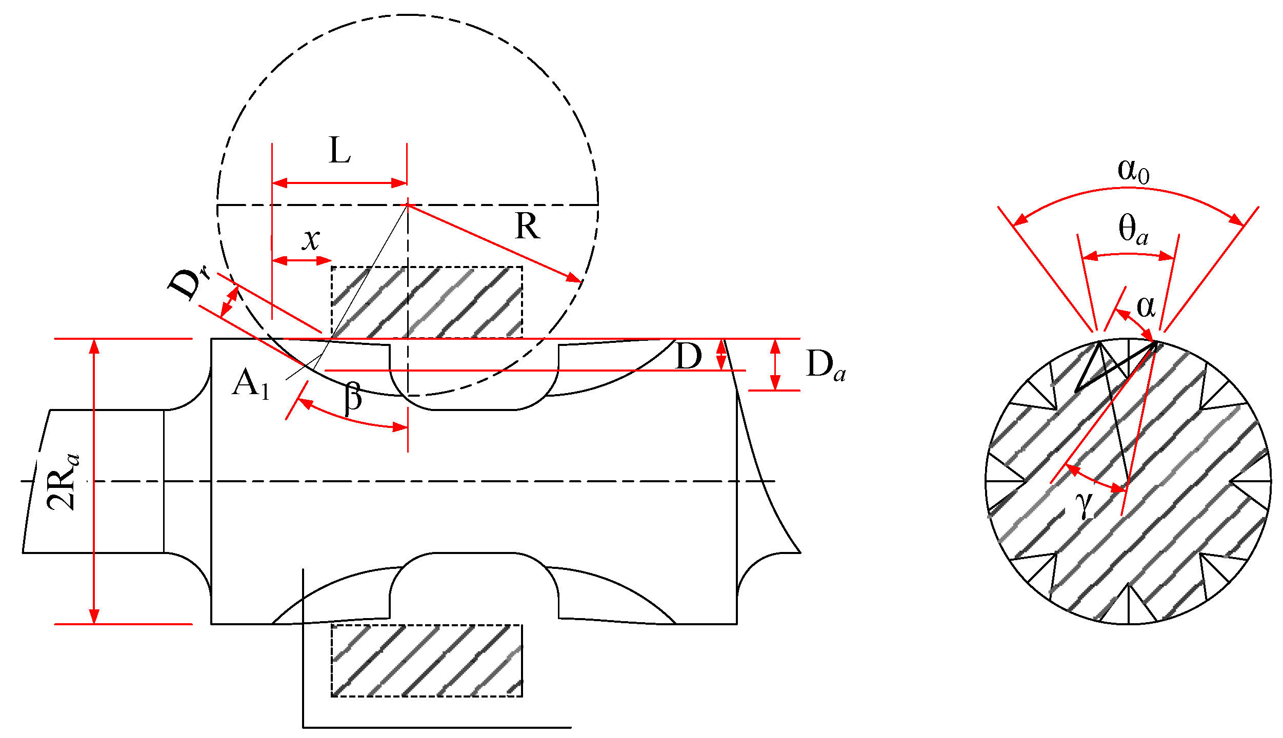
2.2. Design of Control Valve

Following the proposed layout, rated flow rate, and pressure specifications of the independent metering valve following pilot hydraulic control, the structural design of its two-valve spools was performed. Figure 4 presents the cross-sectional view of the symmetrical surface of the main valve spool. P is the high-pressure port, T is the low-pressure port. The red line represents the high-pressure oil circuit, the yellow line represents the low-pressure oil circuit. d is the inlet and outlet diameter, d1 is the sink groove diameter, d2 is the valve spool outer diameter, d3 is the valve stem diameter, and B is the sink groove width.
(1) The maximum flow rate Qmax of the designed main valve reached 60 L/min, and the corresponding inlet and outlet diameter of the main valve spool is presented as follows:
d = 4 Q max π v
where v is the velocity (m/s) and d is the inlet and outlet diameter (mm).
By studying the correlation between the rated flow rate and diameter of different proportional valves, the diameter d can be determined as 8 mm by Equation (1).
(2) The solution for the valve stem diameter d3, valve spool outer diameter d2, sink groove diameter d1, and width B is:
{ d 1 = ( 1.1 1.5 ) × d 2 d 2 = ( 1.1 1.5 ) × d d 3 = ( 1.1 1.5 ) × d B = ( 1.1 1.5 ) × d 3
By measuring the inlet and outlet diameter of 8 mm, according to Equation (2), it can be determined that the valve stem diameter d3 is 9 mm, the valve spool outer diameter d2 is 12 mm, the sink groove diameter d1 is 18 mm, and the width B is 10 mm.
(3) Leakage sealing length l0
The leakage flow Δq of eccentric annular clearance was determined according to the following equation.
Δ q = π d 2 δ 3 Δ p smax 12 μ l 0 ( 1 + 1.5 ε 2 ) 0.6 L / min
where Δpsmax is the pressure difference between the two ends of the fit clearance (MPa); δ is the fit clearance (μm); μ is the oil dynamic viscosity (Pa·s); ε is the relative eccentricity, ε = e/δ; and e is the eccentricity (μm) of the center line of the valve body hole and the center line of the valve spool.
A substitution of the specific parameters: Δpsmax = 25 MPa, δ = 0.01 mm, μ = 3.4 × 10⁻² Pa·s, ε = 1, according to Equation (3), can be obtained.
l 0 0.57 mm
The practical sealing length is significantly larger than the minimum value, which was related to the size of the orifice. Increasing the fit length can not only reduce the leakage, but also increase the system damping.
(4) Throttling groove
The effect of a pressure drop on the valve body space and throttling loss should be considered when designing the throttle groove of the valve port. Here, the valve port pressure drop Δp = 1.4 MPa was taken, and the maximum flow area Amax of the throttle groove was preliminarily estimated to be about [26,27]
A max = Q max c d 2 Δ p / ρ
where Amax is the maximum flow area (mm2) and Δp is the valve port pressure drop (MPa).
According to Equation (5), the maximum flow area Amax of the throttling groove was calculated to be about 25.8 mm2.
The shape of the throttle valve port includes the milling groove type, semicircle moment type, semicircle type, cone type, triangular groove type, L-type, and multi-level throttling grooves composed of the aforementioned throttling grooves in series [26,27]. From the perspective of the linearization of flow regulation, V-shaped grooves were used.
The V-shaped throttling groove is a curved surface formed by cutting the valve spool shoulder with an arc milling cutter, as shown in Figure 5.
L = 2 R × D a D a 2
β = arctan L x R D a
D b = R L x sin ( arctan L x R D a )
D = ( R + L x ) × ( R L + x ) R + D a
tan ( α 0 2 ) = D b tan ( α 2 )
γ = arcsin ( R a D ) sin ( π α 0 2 ) R a
θ a = α 0 2 × γ
A 1 = R a 2 2 × θ a R a ( R a D ) sin ( θ a 2 )
A v = A 1 cos β
where R denotes the tool radius (mm); Da represents the cutting depth (mm); x is the valve opening (mm); L is the length of the throttling groove (mm); D expresses groove depth (mm); Db is the valve body shoulder and section distance (mm); β denotes the angle between the tool center and the valve opening (°); α0 is the processing section angle (°); θa is the angle of the cross section of the valve spool (°); γ represents the angle between the processing section and the radius of the valve spool (°); Ra is the valve spool radius (mm); A1 is the cross-sectional area (mm2); α is the tool angle (°); and Av is the flow area (mm2).
The tool radius R of 8 mm, the cutting depth Da of 3 mm, and the valve spool radius Ra of 6 mm are imported into Equations (6)–(14), and the relationship between the flow area Av of the throttling groove and the displacement x of the valve spool and the angle α of the machining tool of the throttling groove is developed. The program is written and solved in matlab 2016a, as shown in Figure 6.
Figure 6 presents the three-dimensional diagram of the variation of the valve spool displacement from 0 to 4.5 mm and the milling cutter angle from 0.17 rad to 1.74 rad. As depicted in Figure 6, the flow area of the throttling groove increases with the continuous increase of the displacement of the valve spool and the angle between the milling cutter. Compared with the changes in the displacement of the valve spool and the angle between the milling cutter, the displacement of the valve spool has a significant impact on the flow area of the throttling groove.
If the angle of the milling cutter is too large or too small, it will increase the processing difficulty and affect the processing accuracy. The small stroke of the valve spool will lead to excessive sensitivity and affect the accuracy of the control system. The excessive stroke of the spool leads to a decrease in sensitivity and affects the rapidity of the response of the control system. Combined with the practical processing requirements and the flow characteristics of the main valve, the angle of the milling cutter of the V-shaped throttling groove was set at 80°, and the stroke of the valve spool was 3.5 mm.
In summary, the structural dimensions of the two main spools can be determined, and the specific structural parameters are shown in the following table.

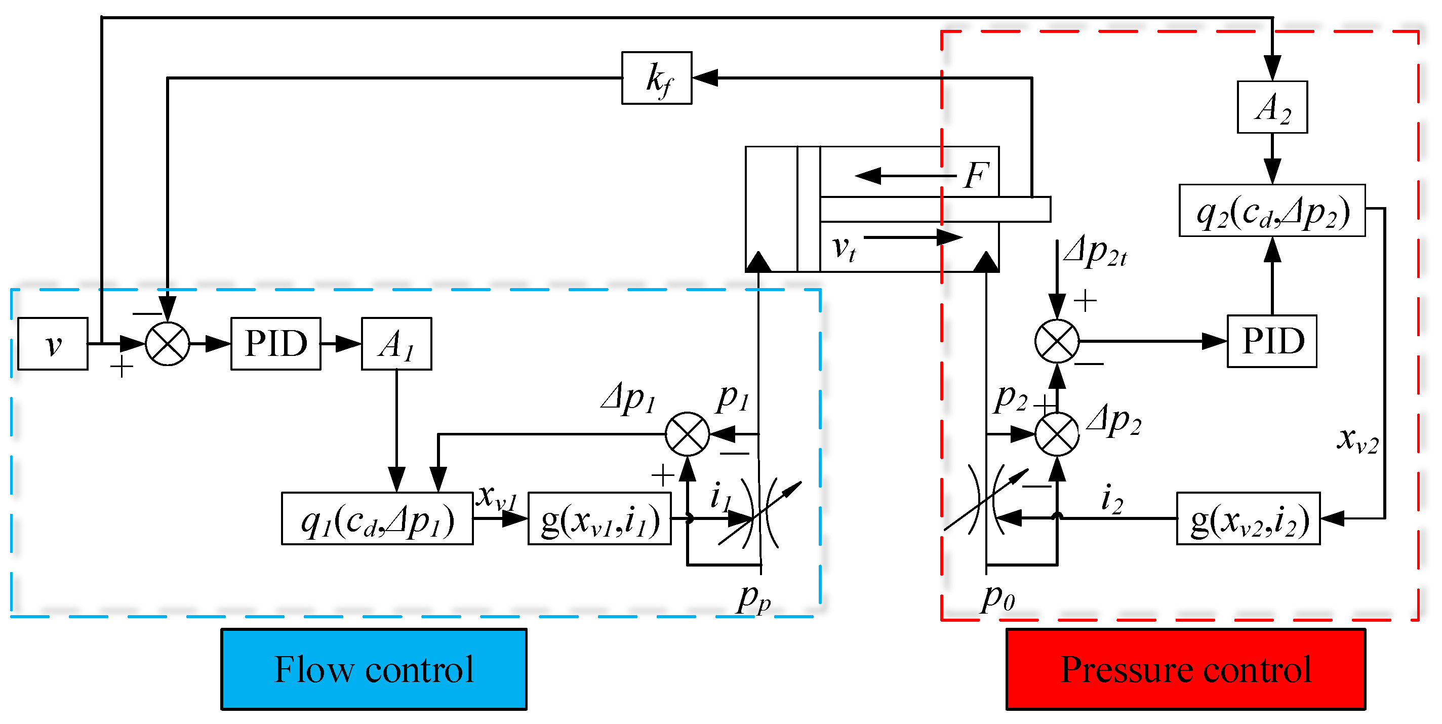
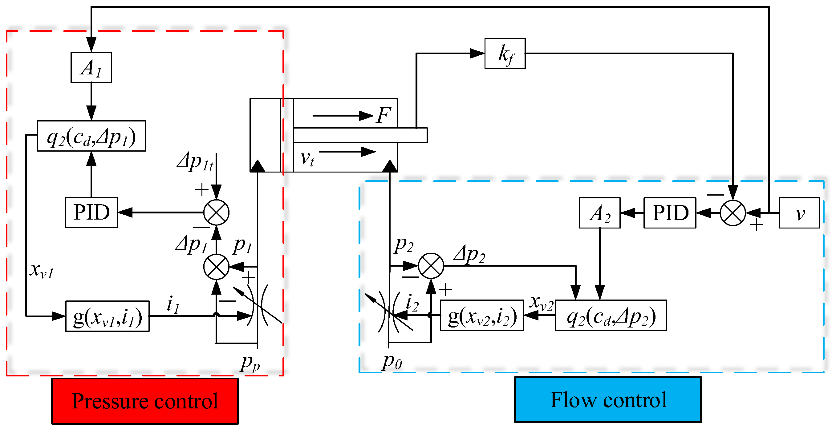
2.3. New Control Strategy

The independent metering system adopts the computational flow feedback strategy to accurately control the actuator speed [28]. Through multiple sensors to detect the pressure difference before and after the control valve, the appropriate flow coefficient was selected to estimate the practical flow of the valve port, and the practical flow served as the negative feedback to make a difference with the input target flow, so as to realize the flow closed-loop control of the proportional valve. The pressure control of the actuator mostly adopts the pressure feedback control strategy. By detecting the pressure difference between the front and back of the proportional valve in real time, the closed-loop comparison with the target pressure difference was performed, and the pressure difference between the front and back of the valve port was changed by controlling the opening change of the proportional valve port.
Under the condition of the actuator impedance extension, the inlet proportional valve was adopted to control the speed of the actuator, and the return proportional valve was adopted to control the back pressure of the actuator to reduce energy consumption. The pressure and flow compound control strategy diagram is shown in Figure 7.
When the actuator exceeded the load, the oil inlet proportional valve was adopted to control the pressure of the oil inlet chamber to keep it low pressure without cavitation. The oil return proportional valve controlled the actuator speed, and the pressure and flow composite control strategy block diagram is presented in Figure 8.
The working mode of the pressure and flow composite control strategy was developed for impedance and overload conditions. However, the load of construction machinery was variable, and a single mode cannot conform to the requirements of practical working conditions. It is necessary to switch the mode according to the load change. For the working conditions with load spectrum, the mapping relationship between the cylinder stroke and the load force should be saved to the controller, and the control strategy can be switched in advance following the load change. In other words, the load mode can be known in advance to switch the impedance and beyond control strategy, such that the complexity of control can be increased, and the application can be limited.
Accordingly, under the condition of no force sensor, the control strategy based on load force direction prediction and two-chamber pressure switching was proposed to investigate the feasibility of working mode switching during load direction change.
The force balance equation of the hydraulic actuator was built as follows:
p 1 A 1 p 2 A 2 = F l
where p1 is the rodless chamber pressure of the hydraulic cylinder (MPa); A1 is the rodless cavity area of the hydraulic cylinder (m2); p2 is the rod chamber pressure of the hydraulic cylinder (MPa); A2 is the rod cavity area of the hydraulic cylinder (m2); and Fl is the load force (N).
The flow rate flowing out of the rod cavity is expressed as:
Q 2 = c d ω x 2 2 ( p 2 p 0 ) ρ
where Q2 is the rod cavity flow rate (L/min); cd is the flow coefficient of the valve port, taking cd = 0.68; ω is the area gradient (m); x2 is the outlet valve spool displacement (mm); p0 is the tank pressure (MPa); and ρ is oil density, ρ = 850 kg/m3.
By substituting Equation (15) into Equation (16), then
x 2 = Q 2 c d ω 2 ( p 1 A 1 F l ) A 2 ρ
When Fl > 0, it is the impedance condition. Thus, the rodless cavity was the flow control, and the rod cavity was the pressure control. According to Equation (17), adjusting the outlet valve spool x2 to maintain p2 at a small value can reduce throttling loss. Setting p2min = 1.5 MPa, the corresponding p1 will also achieve a smaller value, such that energy-saving was improved.
When Fl < 0, it is the overload working condition, and according to Equation (15):
p 1 = F l + A 2 p 2 A 1
Under overload conditions, the rodless chamber was pressure controlled, while the rodless chamber was flow controlled. According to Equation (18), when Fl + A2p2 > 0, no cavitation phenomenon was reported in the rodless cavity of the oil rod, and the pressure of p1 was determined by the load Fl and pressure p2. When Fl + A2p2 < 0, a cavitation phenomenon was reported in the rodless cavity of the oil rod. To maintain p1 > 0 MPa and avoid the cavitation phenomenon, set p1min = 1.5 MPa, and the corresponding p2 will also achieve a smaller value, thus achieving energy-saving performance.
However, in practical work, the load force cannot be obtained in real time, whereas the direction change of the load force can be judged. Following Equation (15), the load force was determined and the direction was judged. The flow control cavity and the pressure control cavity were switched instantaneously in the load direction by logical judgment.
The logic functions H(Fl) and G(Fl) were adopted to output 0, 1 values according to the load direction, so as to control whether the corresponding flow control PID and pressure control PID are effective. When effective, it is the corresponding flow and pressure active control. The logic function is:
H ( F l ) = { 0 , F l , 0 1 , F l 0
G ( F l ) = { 0 , F l , 0 1 , F l 0
Figure 9 presents the control block diagram based on load force direction prediction and two-chamber pressure switching:
Regardless of the speed steering, the target pressure difference is always determined by the target pressure, and the target Δp1min and Δp2min were defined as:
Δ p 1 min = { p 1 min p 0 , v , 0 p s p 1 min , v 0
Δ p 2 min = { p 2 min p 0 , v 0 p s p 2 min , v , 0
where Δp1min is the target pressure difference of the rodless cavity (MPa); p1min is the target pressure of the rodless cavity (MPa); Δp2min is the target pressure difference of the rod cavity (MPa); p2min is the target pressure of the rod cavity (MPa); and ps is the pump source pressure (MPa).
The positive and negative loads were identified by using the actuator force balance Equation (15) and the logic judgment function (19) and (20). When the load Fl > 0, i.e., the load is positive, the proportional valve flow PID controller connected to the rodless cavity is regulated to control the flow of the rodless cavity; the corresponding pressure PID controller output is invalid, and the control strategy is in impedance mode. By setting the target flow using the valve port flow-pressure difference equation and PID closed-loop control, the active flow control of the rodless cavity was achieved. In the process of flow control, the loss of the pressure difference between the front and back of the proportional valve was mechanically compensated by the pressure compensation valve to ensure that the pressure difference between the front and back of the proportional valve port was a constant value, such that the flow change and the opening of the valve port showed a linear relationship. Moreover, the rod cavity flow PID controller was invalid, and the pressure PID output was effective, i.e., the rod cavity performed pressure control. According to Equation (22), setting the target pressure difference, the pressure closed-loop control was formed by comparing with the practical pressure difference to achieve the active control of the pressure of the rod cavity and regulate the opening change of the proportional valve port to change the pressure difference of the proportional valve port.
When the load Fl < 0, i.e., the load was negative, the flow control cavity and the pressure control cavity were switched. When the load varied from positive to negative, the pressure of the rodless chamber dropped sharply during switching. Following the valve port flow–pressure difference equation, the opening of the valve port of the rodless chamber proportional valve turned out to be smaller, such that the oil replenishment speed was less than the volume expansion speed of the rodless chamber, and the suction phenomenon occurred. When the direction of the load force varied, the rodless chamber switched the pressure control mode under the effect of the logic function regulation. To prevent the suction phenomenon, the target pressure difference was set according to Equation (21), and the opening of the valve port of the proportional valve of the rodless chamber was controlled to become larger. On that basis, the aim was to achieve the oil replenishment of the rodless chamber, reduce the pressure difference before and after the valve, improve the pressure of the rodless chamber, and compensate for the sudden drop arising from the reverse of the load force. The rod cavity was switched to flow control, and the active flow control of the rod cavity was achieved using the valve port flow–pressure difference equation and PID closed-loop control. In the process of flow control, the loss of pressure difference between the front and back of the proportional valve was mechanically compensated by the pressure compensation valve to ensure the pressure difference between the front and back of the proportional valve port was a constant value, such that the flow change and the opening of the valve port tended to show a linear relationship.
Compared with the traditional four operating mode switching, the control strategy of the adaptive load force direction prediction can reduce the number of mode switches and notably maintain the continuity of the actuator operation.
Following the principle and new control strategy of the independent metering valve based on pilot hydraulic control, the dynamic characteristics of key parameter changes in the main valve spool, the energy-saving performance of the independent metering system, and the feasibility of the new control strategy were analyzed using hydraulic simulation software AMEsim.

3. Simulation Research

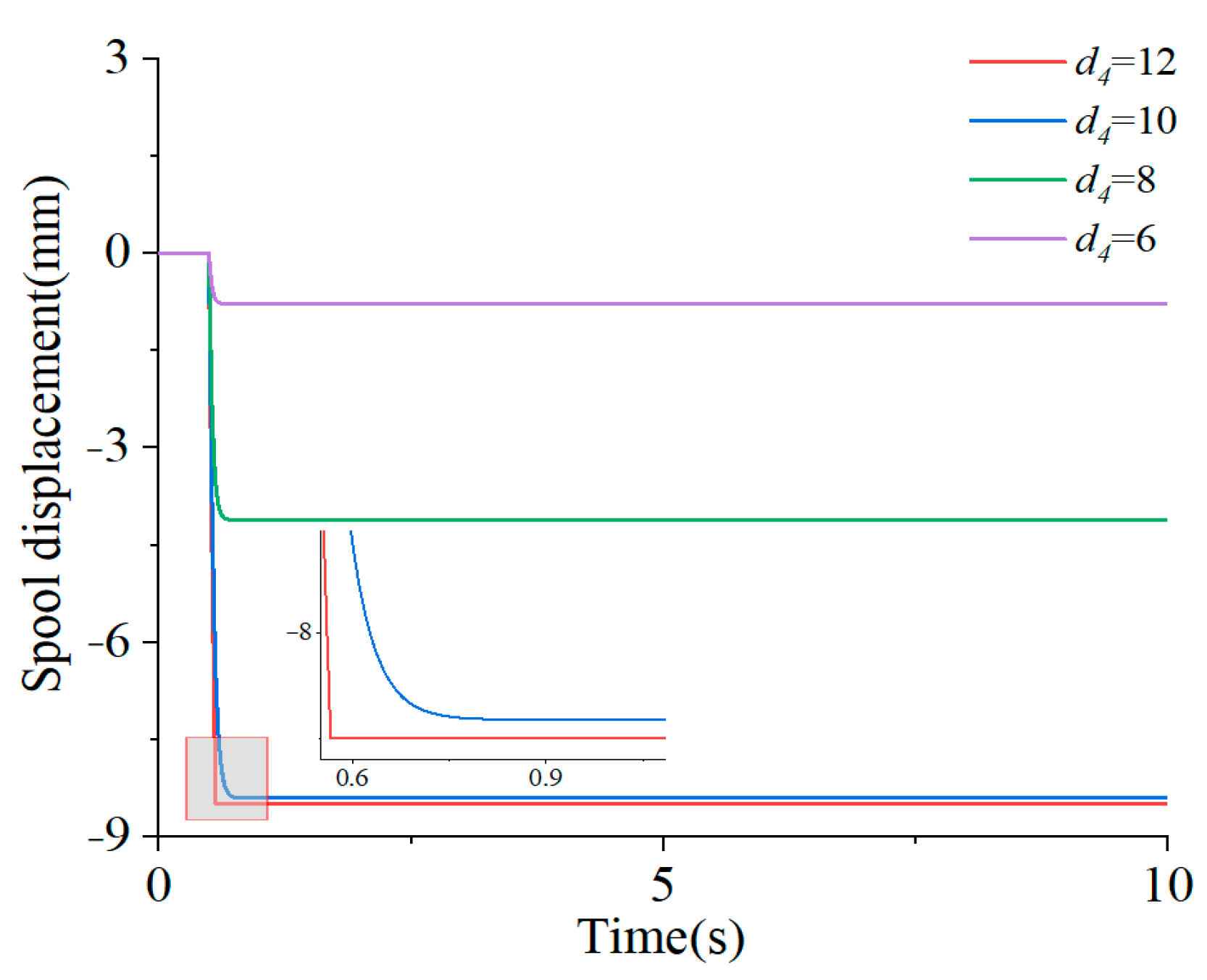
3.1. The Influence of Key Parameters on the Dynamic Characteristics of the Main Valve

Following the principle of the proposed new independent metering valve based on pilot hydraulic control and the size parameters obtained during the design of the main valve spool, the simulation model of the main valve spool was built using the hydraulic simulation software AMEsim. The correlation between the displacement of the main valve spool and the throttling area was imported into the model as a two-dimensional data table, and the parameters were set according to the selected cartridge main relief valve and the electric proportional relief valve. Since the dynamic response characteristics of the main spool in the independent metering valve affect the control performance of the system, the effect of the main valve spool pressure chamber damping and the pilot pressure chamber diameter on the dynamic characteristics of the main valve was investigated based on the simulation model. In the AMEsim simulation, the pressure source P was set at 20 MPa, the outlet pressure of the main relief valve reached 3.5 MPa, the outlet pressure of the proportional relief valve was obtained as 1.82 MPa, the corresponding maximum control current was 1800 mA, and the parameters of the main valve spool were set according to Table 1. Figure 10 presents the built main valve spool simulation model.
(1)
Damping of main spool pressure chamber
The damping effect of the main spool pressure chamber is to stabilize the spool movement and ensure the spool displacement stability of the main spool in the pilot stage pressure oil drive process. However, it also reduces the dynamic response characteristics of the valve spool and affects the response speed of the system. To analyze the influence degree and law of the main spool pressure cavity damping on the spool displacement, the damping holes with diameters of 0.5 mm, 1 mm, 2 mm, 3 mm, 4 mm, and 5 mm were selected to simulate the dynamic response of the spool displacement. The simulation results are presented in Figure 11.
As depicted in Figure 11, when Φ was 5 mm, the peak displacement of the valve spool reached 2.178 mm; when Φ was 4 mm, the peak displacement of the valve spool was obtained as 2.099 mm; when Φ was 3 mm, the peak displacement of the valve spool reached 1.899 mm; when Φ was 2 mm, the peak displacement of the valve spool was obtained as 1.509 mm; when Φ was 1 mm and 0.5 mm, no overshoot was reported in the spool displacement, and the steady-state value reached 1.456 mm. Notably, the damping of the pressure chamber significantly affected the displacement dynamic characteristics of the main spool. With the decrease of the damping hole, the damping turned out to be greater, and the dynamic response characteristics of the spool were improved. However, the damping hole was too small, such that the rapidity of the displacement response of the valve spool would be affected, and the dynamic performance of the control system would be weakened.
In brief, when the damping aperture of the pressure chamber was 1 mm, the valve spool achieved a high dynamic response performance, there was no overshoot phenomenon, the response speed was fast, and the stability was high.
(2)
Pilot pressure chamber diameter
The diameter of the pilot pressure chamber can exert certain effects on the displacement stroke of the main valve spool, ensuring the accuracy of the valve spool displacement under the action of pilot pressure. To analyze the influence degree and law of the diameter of the pilot pressure chamber on the accuracy of the spool displacement, the diameter d4 was selected as 12 mm, 10 mm, 8 mm, and 6 mm, respectively, to simulate the dynamic response of the spool displacement. The simulation results are presented in Figure 12.
As depicted in Figure 12, when d4 was 12 mm, the steady-state value of the spool displacement was 8.5 mm; when d4 was 10 mm, the steady-state value of the spool displacement reached 8.4 mm; when d4 was 8 mm, the steady-state value of the spool displacement was 4.11 mm; and when d4 was 6 mm, the steady-state value of the spool displacement reached 8 mm. Notably, the diameter of the pilot pressure chamber significantly affected the accuracy of the main spool displacement. The larger the diameter, the longer the spool displacement stroke and the better the accuracy. However, the diameter was excessively large, and the response sensitivity of the main spool was too high, such that the difficulty of the accuracy of the spool displacement control was increased.

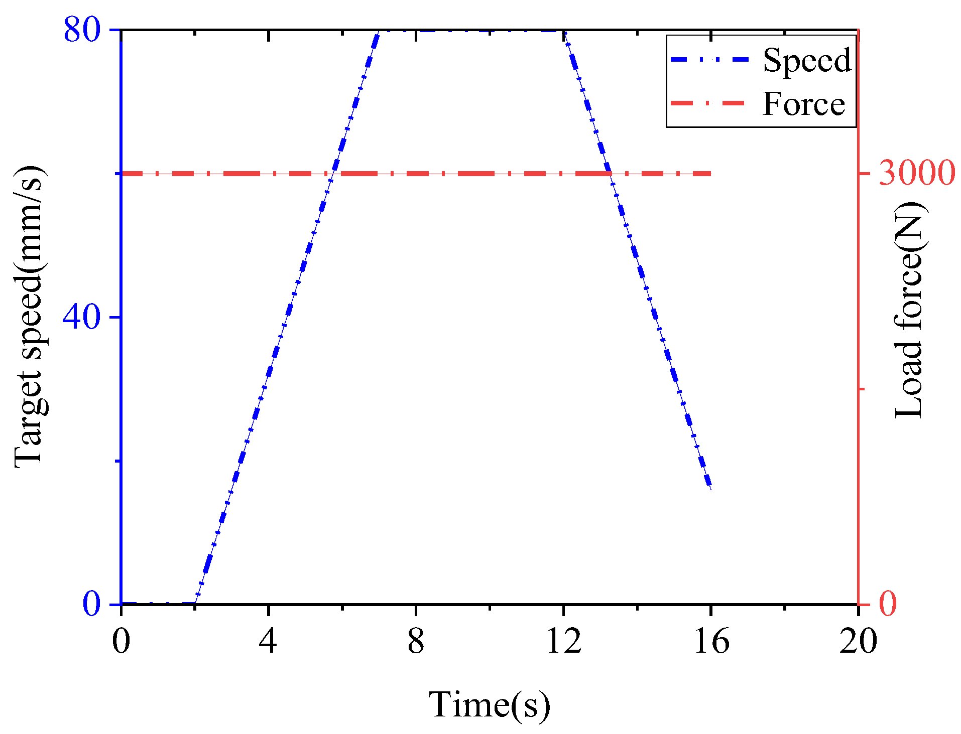
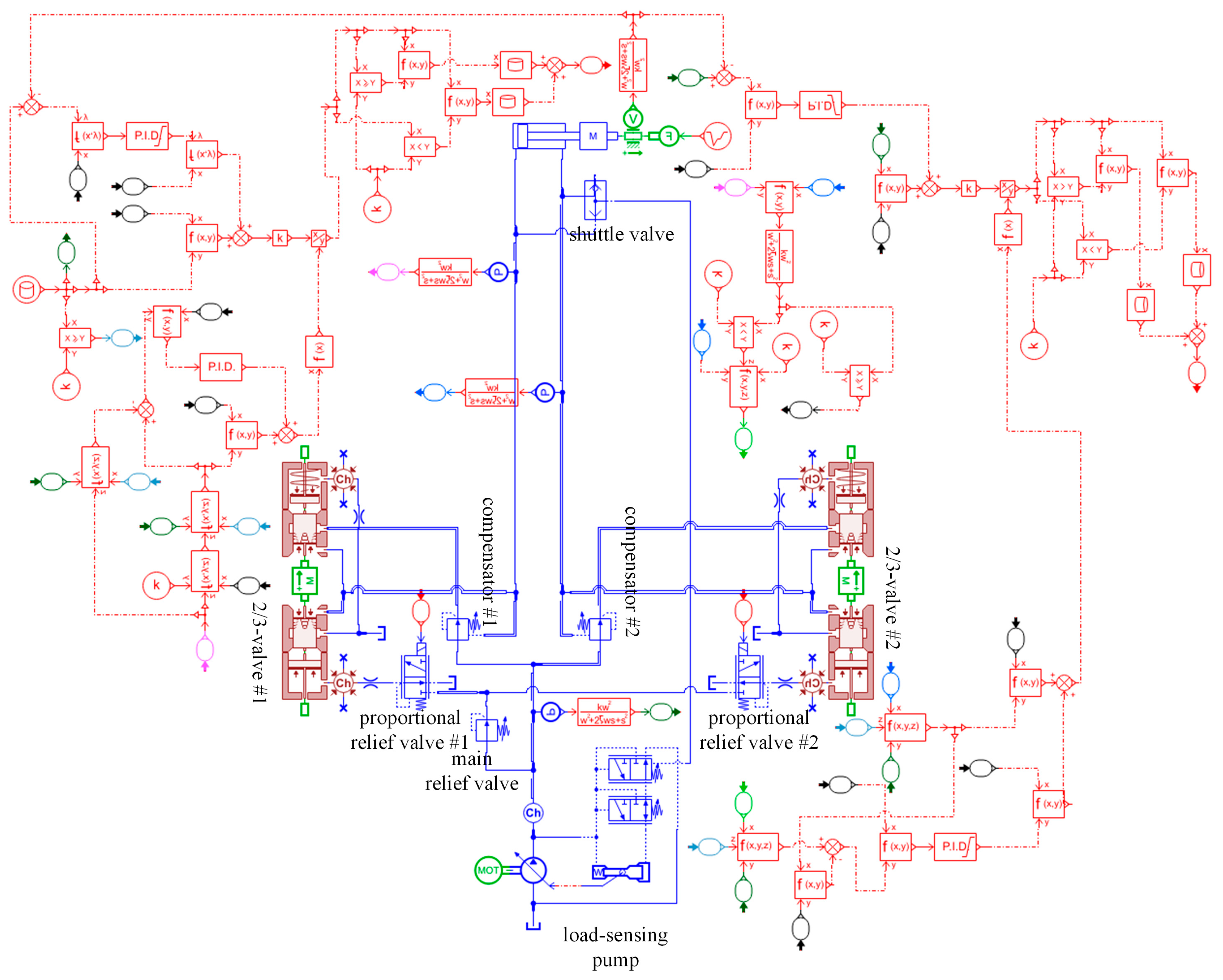
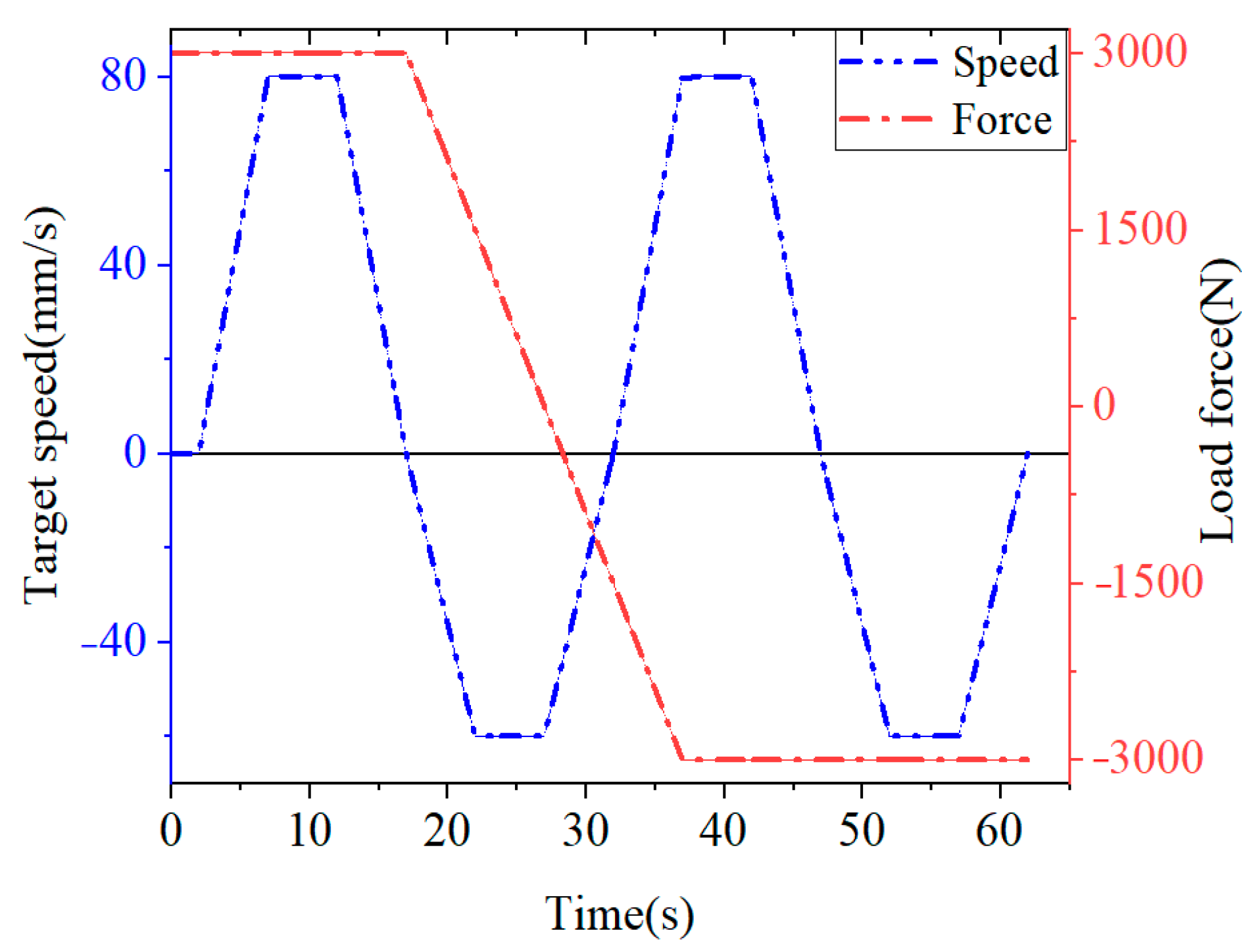
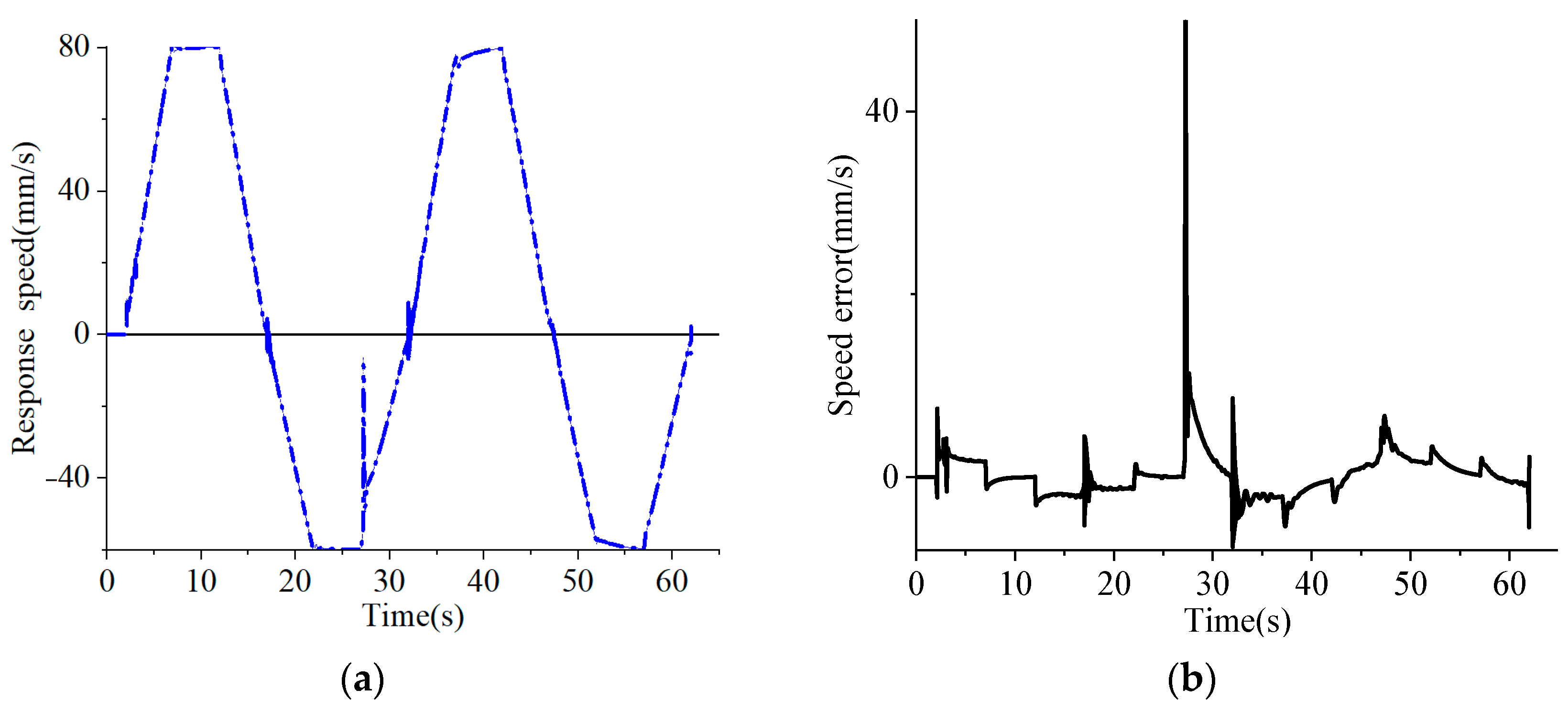
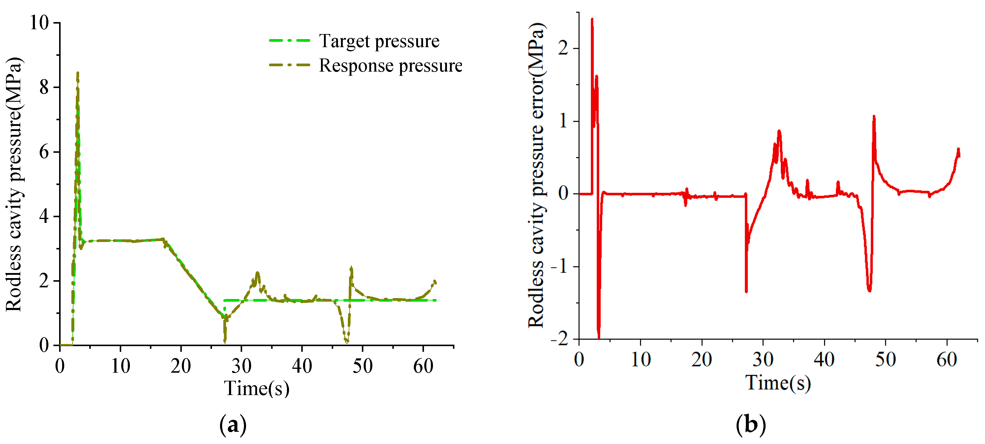
3.2. Analysis of Independent Metering System Based on Pilot Hydraulic Control

To study the effectiveness of the independent metering system based on pilot hydraulic control, the simulation model was built in the hydraulic system simulation software, and the characteristics were compared with the traditional load-sensitive valve control system.
(1) Comparative analysis with the conventional load-sensing valve control system.
Following the working principle of the hydraulic system, the simulation models were built using the AMEsim simulation software for the load-sensitive valve control system of valve front compensation and the independent metering system based on pilot hydraulic control (Figure 13 and Figure 14).
Table 2 lists the performance parameters of the load-sensitive pump and the hydraulic actuator in the simulation model as presented in Figure 13 and Figure 14:
The hydraulic cylinder and the mass block were set as the same, with the aim of investigating the pressure characteristics of the two different hydraulic system actuators and the power characteristics of the pump source, the models of the motor, the load-sensitive pump, and the pressure compensation valve. Figure 15 presents the speed signal and load force changes of the hydraulic actuator.
The pressure compensation independent metering system (PCIMS) is abbreviated as ‘PCIMS’. The load-sensing system, i.e., the traditional load-sensing system, is abbreviated as ‘CLSS’. The pressure of the single actuator and the change curve of the pump source power can be obtained (Figure 16) using the built hydraulic system simulation model.
As depicted in Figure 16a, under the identical constant load condition, the inlet pressure and outlet pressure of the hydraulic actuator in the independent metering system of the inlet pressure compensation are significantly lower than those of the hydraulic actuator in the load-sensitive system. In the initial response stage of the system, the pressure of the two chambers of the hydraulic actuator in the independent metering system appears to be overshoot. The reason is that at the initial state, the low-pressure return valve port connected to the rod chamber of the actuator was fully open. When the system was running, the opening of the return valve port varied from maximum to minimum instantly, causing fluctuations in the pressure of the rod chamber and causing fluctuations in the pressure of the rodless chamber, whereas the overshoot phenomenon quickly disappeared.
As indicated by the comparison of the pump source power characteristics of two different hydraulic systems in Figure 16b, in the process of 2 s to 2.7 s, the variable pump was at the response stage and the power fluctuation occurred, and the energy-saving efficiency cannot be compared. In the process of 2.7 s to 7 s, the average energy-saving efficiency was nearly 51.18%; from 7 s to 12 s, the average energy-saving efficiency reached nearly 40.92%; from 12 s to 16 s, the average energy-saving efficiency was about 53.93%; and the average energy-saving efficiency reached 47.27% in the comprehensive simulation process.
Thus, under constant load conditions, the energy-saving characteristics of the proposed load port independent control system (PCIMS) based on pilot hydraulic control were better than those of the original load-sensitive system (CLSS).
(2) Application of control strategy
The independent metering system based on pilot hydraulic control was built in hydraulic simulation software. Following the predictive control strategy of the load force direction, the dynamic control of the hydraulic system was achieved by logical function. The simulation model is shown in Figure 17.
In the simulation model, the pressure sensor, the hydraulic cylinder displacement sensor, the load force calculation and the pressure difference calculation were all filtered by the second-order filter and then employed for the subsequent calculation. The function of the filter was to eliminate the mutation of the detection pressure difference, delay the mutation of the area calculation result arising from the pressure mutation and the speed mutation, and increase the stability of the control when the valve port pressure difference flow was adopted to calculate the valve flow area.
Following the change of the movement direction of the hydraulic actuator and the direction of the load force, it fell into four stages, i.e., impedance extension, transcendence retraction, impedance retraction, and transcendence extension. As depicted in Figure 18, the target speed and load force change were set, and 0–2 s was the pressure establishment time of the load-sensitive pump. From 2 s to 27 s, the direction of the load force was constantly pointing to the rodless cavity, and the actuator performed the motion command of the impedance extension and transcendence retraction condition. At 17 s, the direction of the actuator speed varied from the impedance extension to the impedance retraction. From 27 s to 62 s and after this period, the load direction was constantly pointing to the rod cavity. The actuator performed the speed command of the working condition of transcendence extension and impedance retraction. At 47 s, the speed direction of the actuator varied, and the working condition varied from transcendence extension mode to impedance retraction mode.
The set target speed and load force were imported into the simulation model, with a total time of 62 s and a step size of 0.001 s. The simulation model of the independent metering was investigated based on load force direction prediction, the speed response characteristics of the system were analyzed, and the pressure variation characteristics of the two chambers of the actuator were investigated.
As depicted in Figure 19, the speed response characteristics were better in the period of 2–17 s. The reasons for these better characteristics are that the direction and size of the load force were constant at this stage, and the actuator was subjected to the impedance extension condition. In the period of 17–27 s, the speed response fluctuated at 17 s, mainly because the magnitude of the load force and the direction of the actuator speed varied at this time, and the actuator varied from the impedance extension to the transcendental retraction condition. On that basis, the speed response varied abruptly. In the period of 27–32 s, the speed response fluctuated notably at 27 s. Since the direction of the load force and the speed of the actuator varied at this time, the actuator varied from transcendental retraction to impedance retraction, such that the speed response mutated. In the period of 32 ~ 37 s, the velocity response fluctuated at 32 s, since the velocity direction of the actuator varied at this time, such that the actuator varied from impedance retraction to transcendence extension, and the velocity response fluctuated. In 47–62 s, the speed fluctuated at 47 s, because the speed direction of the actuator changes at this time, and the actuator varied from transcendence extension to impedance retraction, which makes the speed response fluctuate.
As depicted in Figure 20 and Figure 21, within 2–27 s, the direction of the load force is constantly pointing to the rodless cavity, the rodless cavity is in the flow control mode, and the rod cavity is in the active pressure control mode. At this stage, the ΔP2min of the rod cavity was set at 1.5 MPa, and the pressure of the rodless cavity is in passive control.
From the moment of 2 s, with the increase of the target speed, the flow into the rodless cavity increased, and the flow of the rod cavity increased as well. At the initial state, there was a low-pressure oil port T connected with the rod cavity and the valve port was fully open. When the flow rate of the rod cavity increased, the opening of the valve port varied from the maximum transient to the minimum, which made the pressure of the rod cavity fluctuate at the peak. Following the calculation of Equation (15), the pressure of the rodless cavity also fluctuated at the peak. In 27–62 s, the direction of the load force was constantly pointing to the rod cavity, the rod cavity was in the flow control mode, and the rodless cavity was in the active pressure control mode. At this stage, the ΔP1min of the rodless cavity was set at 1.5 MPa, and the pressure of the rod cavity was passively controlled, which can be determined by Equation (15).
By applying the load force direction prediction control strategy to the independent metering system based on pilot hydraulic control, under the set speed command and load force change law, the anti-cavitation function can be made to conform to the specified back pressure target, and the PID control parameters can be adjusted to achieve more accurate speed control. Through simulation analysis, the effectiveness of the proposed control strategy was demonstrated, which reduced the number of mode switching instances and notably ensured the continuity of the actuator operation.

4. Conclusions

To address the problems of the complex structure, multiple fault points, and difficult troubleshooting of the independent metering valve of the traditional cartridge structure, as well as overly complex multi-mode switching control strategies, the principle of a novel type of the independent metering valve was proposed based on pilot hydraulic control, with a reasonable layout, compact structure, and few fault points, which can be applied to different working conditions. Following the design requirements of flow and pressure, the two-valve spool structure was designed, and the size parameters were obtained. The pressure and flow compound control of the independent metering system under impedance and overload conditions were analyzed, and a new control strategy was designed based on load force direction prediction and pressure switching between the two chambers.
A single spool simulation model was built based on the valve spool parameters to analyze the effect of parameter changes on the dynamic characteristics of the main valve. The simulation model of the independent metering system based on pilot hydraulic control was built, the traditional load-sensitive valve control system under constant load conditions was compared, and the pressure of the two chambers of the hydraulic actuator and the power change of the pump source were analyzed. The simulation results indicated that the independent metering system achieved an average energy-saving efficiency of 47.27%. The new control strategy applied to the independent metering system based on pilot hydraulic control can effectively decrease the complexity of traditional control strategies, reduce the number of multi-mode switching controls, and ensure the continuity of the actuator operation. The research on energy-saving and a new control strategy of the independent metering system based on pilot hydraulic control is conducive to reducing energy consumption, improving system efficiency, increasing system reliability and work efficiency, and achieving the sustainable development of the hydraulic system.
Lastly, it is noteworthy that this study mainly focused on the theoretical and simulation research of the new type of the independent metering system based on pilot hydraulic control. Relevant experimental research will be published in the future.

Author Contributions

Conceptualization, R.G. and Y.G.; methodology, Y.G. and J.Z.; software, J.Y. and J.L.; formal analysis, J.Y.; data curation, Y.Z.; writing—original draft preparation, J.Y.; writing—review and editing, J.Y. and R.G.; supervision, Y.G.; funding acquisition, R.G. All authors have read and agreed to the published version of the manuscript.

Funding

This research was funded by the National Natural Science Foundation of China (12173054, 52075469).

Institutional Review Board Statement

Not applicable.

Informed Consent Statement

Not applicable.

Data Availability Statement

Not applicable.

Acknowledgments

The authors would like to acknowledge Laboratory of Fluid Power Transmission and Control, Yanshan University.

Conflicts of Interest

The authors declare no conflict of interest.

References

  1. Huang, W.; Quan, L.; Ge, L.; Xia, L. Combined velocity and position control of large inertial hydraulic swing mechanism considering energy balance of supply and demand. Autom. Constr. 2019, 106, 102899. [Google Scholar] [CrossRef]
  2. Liu, K.; Gao, Y.; Tu, Z.; Lin, P. Energy-saving analysis of the independent metering system with pressure compensation for excavator’s manipulator. Proc. Inst. Mech. Eng. Part I J. Syst. Control Eng. 2016, 230, 905–920. [Google Scholar] [CrossRef]
  3. Abuowda, K.; Noroozi, S.; Dupac, M.; Godfry, P. A dynamic model and performance analysis of a stepped rotary flow control valve. Proc. Inst. Mech. Eng. Part I J. Syst. Control Eng. 2019, 233, 1195–1208. [Google Scholar] [CrossRef]
  4. Liu, Q.; Du, H.; Cai, Z.; Guo, K.; Fang, J. Application research of electro-hydraulic servo steering system based on independent metering system. Proc. Inst. Mech. Eng. Part D J. Automob. Eng. 2022, 09544070221139553. [Google Scholar] [CrossRef]
  5. Nguyen, T.; Do, T.; Ahn, K. A Study on a New Independent Metering Valve for Hydraulic Boom Excavator. Appl. Sci. 2022, 12, 605. [Google Scholar] [CrossRef]
  6. Chen, G.; Wang, J.; Wang, S.; Ma, L. Separate meter in and separate meter out energy saving control system using dual servo valves under complex load conditions. Trans. Beijing Inst. Technol. 2016, 36, 1053–1058. [Google Scholar]
  7. Ahamad, M.; Dinh, Q.; Nahian, S.; Ahn, K. Development of a New Generation of Independent Metering Valve Circuit for Hydraulic Boom Cylinder Control. Int. J. Autom. Technol. 2015, 9, 143–152. [Google Scholar] [CrossRef]
  8. Zhong, Q.; Bao, H.; Li, Y.; Hong, H.; Zhang, B.; Yang, H. Investigation into the independent metering control performance of a twin spools valve with switching technology-controlled pilot stage. Chin. J. Mech. Eng. 2021, 34, 91. [Google Scholar] [CrossRef]
  9. Zhong, Q.; Zhang, B.; Bao, H.; Hong, H.; Ma, J.; Ren, Y.; Yang, H.; Fung, R. Analysis of pressure and flow compound control characteristics of an independent metering hydraulic system based on a two-level fuzzy controller. J. Zhejiang Univ.-Sci. A 2019, 20, 184–200. [Google Scholar] [CrossRef]
  10. Liu, K.; Kang, S.; Qiang, H.; Yu, C. Cavitation Prevention Potential of Hydromechanical Pressure Compensation Independent Metering System with External Active Load. Processes 2021, 9, 255. [Google Scholar] [CrossRef]
  11. Choi, K.; Seo, J.; Nam, Y.; Kim, K. Energy-saving in excavators with application of independent metering valve. J. Mech. Sci. Technol. 2015, 29, 387–395. [Google Scholar] [CrossRef]
  12. Hu, H.; Zhang, Q. Realization of programmable control using a set of individually controlled electrohydraulic valves. Int. J. Fluid Power 2002, 3, 29–34. [Google Scholar] [CrossRef]
  13. Shi, J.; Quan, L.; Zhang, X.; Xiong, X. Electro-hydraulic velocity and position control based on independent metering valve control in mobile construction equipment. Autom. Constr. 2018, 94, 73–84. [Google Scholar] [CrossRef]
  14. Ding, R.; Zhang, J.; Xu, B.; Cheng, M.; Pan, M. Energy efficiency improvement of heavy-load mobile hydraulic manipulator with electronically tunable operating modes. Energy Convers. Manag. 2019, 188, 447–461. [Google Scholar] [CrossRef]
  15. Koivumäki, J.; Zhu, W.; Mattila, J. Energy-efficient and high-precision control of hydraulic robots. Control Eng. Pract. 2019, 85, 176–193. [Google Scholar] [CrossRef]
  16. Liu, B.; Quan, L.; Ge, L. Research on the performance of hydraulic excavator boom based pressure and flow accordance control with independent metering circuit. Proc. Inst. Mech. Eng. Part E J. Process Mech. Eng. 2017, 231, 901–913. [Google Scholar] [CrossRef]
  17. Bao, H.; He, D.; Zhang, B.; Zhong, Q.; Hong, H.; Yang, H. Research on Dynamic Performance of Independent Metering Valves Controlling Concrete-Placing Booms Based on Fuzzy-LADRC Controller. Actuators 2023, 12, 139. [Google Scholar] [CrossRef]
  18. Lyu, L.; Chen, Z.; Yao, B. Advanced valves and pump coordinated hydraulic control design to simultaneously achieve high accuracy and high efficiency. IEEE Trans. Control Syst. Technol. 2020, 29, 236–248. [Google Scholar] [CrossRef]
  19. Abuowda, K.; Noroozi, S.; Dupac, M.; Godfrey, P. Algorithm design for the novel mechatronics electro-hydraulic driving system: Micro-independent metering. IEEE Int. Conf. Mechatron. (ICM) 2019, 1, 7–12. [Google Scholar]
  20. Nguyen, T.; Do, T.; Nguyen, V.; Ahn, K. High Tracking Control for a New Independent Metering Valve System Using Velocity-Load Feedforward and Position Feedback Methods. Appl. Sci. 2022, 12, 9827. [Google Scholar] [CrossRef]
  21. Su, W.; Ren, W.; Sun, H.; Liu, C.; Lu, X.; Hua, Y.; Wei, H.; Jia, H. Data-Based Flow Rate Prediction Models for Independent Metering Hydraulic Valve. Energies 2022, 15, 7699. [Google Scholar] [CrossRef]
  22. Lyu, L.; Chen, Z.; Yao, B. Energy saving motion control of independent metering valves and pump combined hydraulic system. IEEE/ASME Trans. Mechatron. 2019, 24, 1909–1920. [Google Scholar] [CrossRef]
  23. Li, C.; Lyu, L.; Helian, B.; Chen, Z.; Yao, B. Precision motion control of an independent metering hydraulic system with nonlinear flow modeling and compensation. IEEE Trans. Ind. Electron. 2021, 69, 7088–7098. [Google Scholar] [CrossRef]
  24. Hu, S.; Wang, L.; Li, Y.; Zhang, L. Variable Universe Fuzzy Controller for an Independent Metering System of Construction Machinery. Processes 2023, 11, 901. [Google Scholar] [CrossRef]
  25. Ding, R.; Cheng, M.; Zheng, S.; Xu, B. Sensor-fault-tolerant operation for the independent metering control system. IEEE/ASME Trans. Mechatron. 2020, 26, 2558–2569. [Google Scholar] [CrossRef]
  26. Ji, H.; Wang, D.; Liu, X.; Fu, X. Flow control characteristic of the orifice in spool valve with notches. Trans. Chin. Soc. Agric. Mach. 2009, 40, 199–202. [Google Scholar]
  27. Wang, A.; Kuang, L.; Zhang, X. A study on flow coefficient of combined throttling groove in spool valves. J. Xian Jiaotong Univ. 2018, 52, 110–117. [Google Scholar]
  28. Wang, R.; Xu, B.; Wang, D.; Zhang, C. Research on Intelligent Flow Control Method Based on Proportional Directional Valve. Trans. Beijing Inst. Technol. 2020, 40, 486–490. [Google Scholar]
Figure 1. Traditional valve control system and independent metering system. (a) Traditional valve control system; (b) independent metering system.
Sustainability 15 13359 g001
Figure 2. Independent metering valve based on pilot hydraulic control.
Sustainability 15 13359 g002
Figure 3. Working principle of independent metering valve. (a) Hydraulic cylinder piston rod extension; (b) hydraulic cylinder piston rod retracted.
Sustainability 15 13359 g003
Figure 4. Two-valve spools’ structure.
Sustainability 15 13359 g004
Figure 5. Geometric characteristics of V-shaped groove.
Sustainability 15 13359 g005
Figure 6. Relationship between throttling area and spool displacement, milling cutter angle.
Sustainability 15 13359 g006
Figure 7. Impedance condition control strategy.
Sustainability 15 13359 g007
Figure 8. Overload condition control strategy.
Sustainability 15 13359 g008
Figure 9. Control strategy block diagram of adaptive load force direction.
Sustainability 15 13359 g009
Figure 10. Main spool simulation model.
Sustainability 15 13359 g010
Figure 11. The influence of the damping aperture of the pressure chamber on the dynamic stability of the spool.
Sustainability 15 13359 g011
Figure 12. Effect of pilot pressure chamber diameter on dynamic accuracy of spool.
Sustainability 15 13359 g012
Figure 13. Traditional load sensitive system.
Sustainability 15 13359 g013
Figure 14. Independent metering system based on pilot hydraulic control.
Sustainability 15 13359 g014
Figure 15. Setting the target speed signal and load force of the valve control system.
Sustainability 15 13359 g015
Figure 16. Actuator pressure and pump power. (a) Actuator pressure; (b) pump power.
Sustainability 15 13359 g016
Figure 17. Simulation model of independent metering based on load force direction prediction.
Sustainability 15 13359 g017
Figure 18. Setting speed signal and load force.
Sustainability 15 13359 g018
Figure 19. Target speed response and speed error. (a) Speed response; (b) speed error.
Sustainability 15 13359 g019
Figure 20. Pressure response and pressure error of rodless cavity. (a) Pressure response of rodless cavity; (b) rodless cavity pressure error.
Sustainability 15 13359 g020
Figure 21. Rod cavity pressure response and pressure error. (a) Pressure response of rod cavity; (b) rod cavity pressure error.
Sustainability 15 13359 g021
Table 1. Structural parameters of main spool.
NumberVariableValueNumberVariableValue
1total length of valve spool71.5 mm6stem diameter9 mm
2spool displacement3.5 mm7pressure-equalizing groove0.2 mm × 0.5 mm
3throttling groove shapeV8sinking slot diameter18 mm
4negative coverage0.5 mm9width of sinking slot10 mm
5valve spool outer diameter12 mm10oil channel diameter8 mm
Table 2. Hydraulic actuator and pump source parameter table.
VariableParameterVariableParameter
cylinder piston diameter D (mm)40leakage flow (L/min/MPa)0.02
cylinder piston rod diameter d (mm)25damping coefficient (N/m/s)120
hydraulic cylinder stroke L (mm)1200cylinder dead zone (cm3)50
Ls pump displacement (mL/r)100Ls valve setting pressure (MPa)2
cut-off valve pressure (MPa)28motor speed (r/min)1500
Disclaimer/Publisher’s Note: The statements, opinions and data contained in all publications are solely those of the individual author(s) and contributor(s) and not of MDPI and/or the editor(s). MDPI and/or the editor(s) disclaim responsibility for any injury to people or property resulting from any ideas, methods, instructions or products referred to in the content.

