1. Introduction
With the continuous advancement of China’s western development strategy, in order to meet the needs of China’s traffic growth and improve people’s travel conditions, road traffic construction continues to extend to some remote mountainous areas. The geological conditions for engineering are worsening, and the construction difficulty is increasing, requiring the construction of a large number of bridges and tunnels [
1]. The mountainous area in southwest Yunnan is known as the Geological Museum of China. The geological conditions are complex, and construction is difficult. Various geological problems emerge, such as large deformations of weakly cemented surrounding rock, mud and water inrush, geological bedding bias, high ground stress, and other geological problems [
2,
3,
4]. The joints and cracks develop in the weakly cemented surrounding rock, and the disturbance from engineering makes the joints and cracks of the surrounding rock more developed. The soft rock containing montmorillonite expands when it encounters water, resulting in greater expansion pressure on the supporting body. Due to its characteristics of water softening, rheology, and low rock strength, the deformation of the surrounding rock becomes particularly large after the engineering exposure, and it weathers easily and is difficult to support. Hazards such as initial support deformation, collapse, and secondary lining cracking occur [
5,
6,
7,
8,
9], leading to a slow construction progress and increased construction costs, and threatening the safety of personnel and equipment. Sometimes, unoccupied airborne systems (UASs), also known as drones, must be used for construction management [
10].
At present, the large deformation control of weakly cemented surrounding rock has become a hot research topic in the engineering field. Yu et al. [
11] studied different lateral pressure coefficients (λ), namely the angle between the roadway and the maximum horizontal principal stress (α) and the impact of typical lithological combinations on the deformation of weakly cemented roadway surrounding rocks. Liu et al. [
12] used the 11,303 return air road of the Hongqingliang coal mine as the engineering background to study the influence of tunnel structural morphology on stress distribution characteristics and stability of weakly cemented soft rock tunnels, the stress and deformation evolution law of weakly cemented soft rock tunnels, and the plastic zone of top and bottom coal seam support. Vrettos, C. et al. [
13] applied the available numerical analysis method of lateral two-dimensional response to the case study of stations and inter station tunnels on subway lines in seismic regions. Two continuum methods were considered: (a) time-domain dynamic finite element analysis and (b) quasi-static analysis. The cross-sectional force is determined for typical seismic vibrations. They are compared with each other and compared with the results obtained from the static design of excavation support. According to different deformation mechanisms, the large deformation of weakly cemented surrounding rock can be divided into two types: plastic extrusion type and water expansion type. The large deformation of weakly cemented surrounding rock in Baishitou Tunnel of the Dali–Lincang railway project is the plastic extrusion type, that is, the extrusion deformation of surrounding rock due to the force exceeding its strength [
14,
15,
16]. At present, the traditional methods used to solve large deformation of weakly cemented surrounding rock mainly include increasing the reserve amount, increasing the support strength, and changing the excavation method [
17,
18,
19,
20]. In the past, most of the supporting means were passive. Now, with the development of equipment manufacturing, some active supporting means have begun to be applied in the tunnel field, including the bolt support technology [
21,
22]. The yielding anchor bolt support adopted in this article is an active support method based on the theory of the surrounding rock loosening circle, which allows the surrounding rock to undergo certain deformation and release a certain amount of dynamic pressure in the early stage of support, reducing the probability of anchor failure. At the same time, the yielding anchor bolt can enable the surrounding rock to have a certain bearing capacity [
23,
24,
25,
26] and is assisted by initial support methods such as an I25 steel arch and sprayed concrete, thus achieving the goal of effectively controlling the large deformation of weakly cemented surrounding rocks [
27,
28,
29].
At the same time, in the construction process of Baishitou Tunnel of the Dali–Lincang railway project, the problem of geological bedding bias generally occurs, which leads to strong pressure on one side of the tunnel and increased displacement. The initial support penetration limit and shotcrete falling block often occur in the positions where geological bedding bias is serious, thus increasing the difficulty of tunnel support [
30,
31]. The influence of geological bedding bias pressure is more pronounced in weakly cemented surrounding rock tunnels. Geological bedding bias has also been a hot issue in the field of engineering construction, and it needs to be solved urgently. Ge et al. [
32] took the Qijiazhuang Tunnel as the research object, and they used the discrete element method to analyze the results of the stress, vertical displacement, and surface deformation of the surrounding rock of the geological bedding bias tunnel under different working conditions as well as the mechanism of system anchor support from a microscopic perspective. YanLi et al. [
33] proposed a comprehensive method that combines monitoring technology with discrete element analysis (3DEC) numerical simulation to analyze the deformation characteristics of layered-rock tunnel-surrounding rock and the deformation laws of bias tunnels. Wu et al. [
34] took the Wuduxi Tunnel as an engineering example to study the failure behavior and surrounding rock deformation mechanism of the support structure of a deeply buried geological bedding bias tunnel. Hu et al. [
35] investigated the mechanical properties of surrounding rock and supporting structure of a shallow-buried bias tunnel crossing the soil–rock interface using a combination of model tests and numerical simulations. Guo et al. [
36] analyzed the overall stability and instability failure mechanism of the shallow tunnel under unsymmetrical pressure during the operation period by using the strength reduction method in light of the operational safety of the tunnel, proposed a reasonable monitoring strategy, and also constructed a monitoring index system. Ma et al. [
37] conducted a numerical study of the influence of karst caves on tunnel stability using the Discrete Lattice Spring Model (DLSM).
During the construction of Baishitou Tunnel of the Dali–Lincang railway project, the problems of geological bedding bias and large deformation of weakly cemented surrounding rock were encountered simultaneously. The complex geological conditions provided research material for scientific and technological workers. Therefore, it is necessary to study the variation law of stress and displacement and control technology for the large deformation of the weakly cemented surrounding rock of the Baishitou Tunnel of the Dali–Lincang railway project. Under the premise of ensuring basic requirements such as tunnel construction quality and safety, a reasonable support plan is provided. This plan can save resources to the maximum extent and achieve the goal of green, efficient, and sustainable tunnel construction.
2. Engineering Background
The Baishitou Tunnel of the Dali–Lincang railway project, located in the mountainous area of southwest Yunnan Province, has complex geological conditions, with many geological folds, and the unfavorable geology mainly includes geological bedding pressure, radioactivity, harmful gases, etc. The strata in the section DK161 + 960~DK167 + 60 are mainly schist with carbonaceous schist and chlorite schist, belonging to the class Ⅳ weakly cemented surrounding rock. The total length of the tunnel is 9375 m, and the maximum buried depth is about 300 m. The angle between the rock strike and the line is 2~28° < 30°, with an apparent inclination angle of 25~52°. The rock dip angle is in the range of 20~70°, and there is geological bedding bias on the right side of the tunnel.
The Baishitou Tunnel is designed according to Grade V surrounding rock, and the construction method of three bench reserved core soil is adopted. The support parameters during construction are steel frame with a full-ring I20b steel frame, and the distance is 0.6 m. The arch part is φ25 combined hollow bolt, the length is 5 m, the side wall is φ22 mortar bolt, the length is 5 m, and the longitudinal and circumferential spacing is 1.0 m.
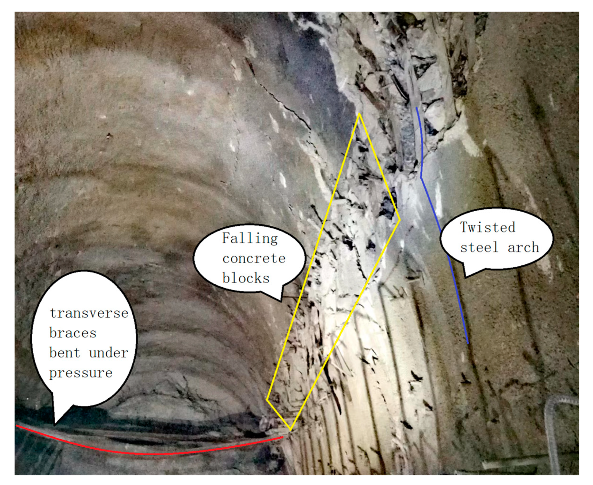
After the construction of the main tunnel began, the deformation of the surrounding rock was significant, and the added transverse braces were severely bent. The right steel arch frame of the line was seriously twisted, and concrete blocks from the initial support fell off, as shown in
Figure 1. The maximum convergence point could reach 1 m, and the convergence could reach about 8 cm per day.
3. Surrounding Rock Monitoring
3.1. Results of Initial Support Stress Monitoring
At the DK163 + 720 mileage of the tunnel, using a YH-45 pressure box for initial support stress monitoring, an initial support stress monitoring section was arranged. When each step of the tunnel was excavated to this section, technicians installed five pressure boxes between the arch and surrounding rock of this section, respectively located at the vault, left and right spandrels, and left and right arch waists of this section. The pressure box data were recorded daily, and the statistical results of the stress between the surrounding rock and the initial support of the monitoring section are shown in
Figure 2. As can be seen from
Figure 2, when the upper step was excavated on August 16, the pressure boxes located at the arch and at the left and right spandrels were buried. After that, the surrounding rock pressure gradually increased, especially the arch pressure, with a faster growth rate. On 22 August, when the middle step was excavated, the pressure box of the left and right arch waists was buried. The surrounding rock pressure continued to increase, but the pressure on the right side increased significantly faster, showing a bias characteristic. From the excavation of the lower step on 9 September to the excavation of the invert on 14 September, the pressure on the right spandrel increased in steps to a maximum of 0.832 MPa, resulting in a sharp bias, which led to a large deformation of the steel arch, and the initial support began to violate the limit. After 54 days of tunnel excavation, the pressure reached a stable value. By 26 September, the stress was distributed between the surrounding rock of the tunnel section and the initial branch, as shown in
Figure 3. The surrounding rock pressure on the vault and left and right spandrels of the tunnel was relatively high. At the same time, the surrounding rock pressure was severely affected by the tunnel bedding bias. The pressure on the right spandrel reached 0.677 MPa, which is significantly greater than the pressure on the left spandrel of 0.233 MPa, and the pressure value on the vault was 0.450 MPa.
3.2. Monitoring Measurement Results
Surveyors used the GM-101/102 total station to monitor and measure the DK163 + 720 section of the tunnel every day, and they obtained the displacement values of the five measuring points of the vault, left and right spandrels, and left and right arch waists of this section as they changed over time, as shown in
Figure 4. From
Figure 4, one can see the displacements of the vault and left and right spandrels began to be detected on 8 September, and abnormal fluctuations occurred on 9 September when the lower step was excavated, and the data were stable on 10 September. However, the deformation of the right spandrel was larger than that of the left, and then the deformation increased steadily. On 11 September, monitoring of the displacement of the left and right arch waist measurement points began. On 14 September, the invert excavation showed that the deformation of the tunnel-surrounding rock increased sharply, and the deformation of the right spandrel reached a maximum of 0.53 m. The deformation distribution of the initial branch of the DK163 + 720 section as of 25 September is shown in
Figure 5. Affected by its low strength, the weakly cemented surrounding rock had the characteristics of fast deformation speed and large deformation amount. At the same time, the surrounding rock was severely affected by geological bedding bias, with the deformation of the right spandrel reaching 0.493 m, which is significantly greater than the deformation of the left spandrel of 0.306 m, while the subsidence of the vault was relatively small, reaching 0.216 m.
4. Analysis and Numeric Calculator
4.1. Support Scheme Design
Pressure relief support refers to the installation of pressure relief components on the support unit, making the support unit scalable, and including items such as yielding anchor bolts and retractable U-shaped steel brackets. The supporting mechanism is meant to reserve certain space for surrounding rock deformation and supports it after releasing certain pressure from the surrounding rock. Ordinary bolts fail easily after large deformations, so the previous bolt system of arch and side wall was changed to yielding anchor bolt. According to tunnel construction standards and specifications such as “Technical Specification for Highway Tunnel Construction JTG/T 3660-2020” and “Q/CR 9248-2020 Technical Specification for Railway Tunnel Anchor Bolt Support”, combined with actual geological conditions and construction conditions on site, support parameters were determined. The length of the anchor rods were selected as 5 m, with a longitudinal spacing of 1 m and a circumferential spacing of 1.0 m.
Due to the deeply buried the tunnel, high ground stress, and the influence of bias pressure, the surrounding rock pressure is high. In order to select the appropriate support strength, I20, I22, and HW175 steels were adopted on site, but they all failed to meet the requirements. Currently, the rigid support frame has been changed to a full-ring I25b steel frame, with a spacing of 0.6 m for strong support.
4.2. Establishing a Numerical Model and Determining the Simulation Scheme
The numerical simulation was calculated using the finite element program FLAC3D, and the establishment of the numerical model and the mesh division were carried out using the software ANSYS 16.0. The size of the created model is XYZ = 80 m × 50 m × 60 m, with 80,200 cells and 56,763 nodes. The model diagram is shown in
Figure 6. The horizontal displacement of the boundary in the X-axis and Y-axis directions of the model, the vertical displacement of the lower surface in the Z-axis direction, and the upper surface of the model as a free surface are constrained, and an overburdened pressure of 5.68 Mpa is applied to it. The depth of the tunnel is 250 m. The dip angle of strata is 45°, and the angle between strata strike and tunnel strike is θ = 0°. The mechanical parameters of the model are shown in
Table 1. The simulation of the tunnel’s initial branch is realized via shell unit and cable unit. Two working conditions are considered. Working conditions 1 and 2 are “I20 I-steel + system bolt” and “I25 I-steel + yielding anchor bolt”, respectively. Specific supporting parameters are shown in
Table 2 and
Table 3.
4.3. Simulation Results Analysis
The simulation results are shown in
Figure 7,
Figure 8,
Figure 9,
Figure 10 and
Figure 11, (a) in
Figure 7,
Figure 8,
Figure 9,
Figure 10 and
Figure 11 represents working condition 1, and (b) represents working condition 2.
Figure 7 is the plastic failure comparison between working condition 1 and working condition 2,
Figure 8 is the stress change comparison between working condition 1 and working condition 2,
Figure 9 is the longitudinal plastic failure comparison between working condition 1 and working condition 2,
Figure 10 is the longitudinal stress change comparison between working condition 1 and working condition 2, and
Figure 11 is the initial stress comparison between working condition 1 and working condition 2.
Analyzing
Figure 7, the plastic failure of surrounding rock on the right spandrel and the left lower step is serious after tunnel excavation due to bias pressure. Under condition 1, the failure depth of the surrounding rock reaches 2.3 m, and under condition 2, the plastic failure depth is 1.1 m. From
Figure 8, the vertical stress of surrounding rock on the right spandrel and left lower step of the tunnel is relatively large due to bias pressure, and locally reaches 11 MPa. The original rock pressure of the vault and tunnel bottom is released, while the vertical stress is small. Under condition 2, the surrounding rock stress is released, and the stress concentration is weakened. From
Figure 9, the plastic failure depth of the face reaches 2 m under condition 1, and it decreases to 1 m under condition 2. From
Figure 10, one can see that stress concentration occurs at the top and bottom of the face under condition 1, and the maximum stress is 4.56 MPa. Under condition 2, the maximum stress is reduced to 4.44 MPa. From
Figure 11, one can see that the initial force of the left lower step is the largest. Under condition 1, the maximum force reaches 12 MPa, and under condition 2, the maximum force reaches 31.6 MPa. This is due to the use of strong support under condition 2, and the initial support has better resistance to surrounding rock pressure.
In order to analyze the deformation of surrounding rock under condition 2, the displacement of five measuring points including the vault, left and right spandrels, and left and right arch waists were recorded for every 100 steps of operation during the calculation of the model, and the displacement of measuring points and the amount of roof separation were counted when the excavation of the palm surface was 0 m, 5 m, 10 m, 15 m, and 20 m away from the monitoring section, as shown in
Figure 3.
Analysis of
Figure 12 shows that after tunnel excavation, the farther away from the tunnel face, the greater the deformation of the surrounding rock. When the distance from the tunnel face is greater than 20 m, the surrounding rock basically reaches stability, and the displacement of the right spandrel is the largest, reaching 11 cm. The displacement of the left lower step is larger than that of the right, reaching 8.9 cm. The roof separation is about 4.1 cm, and the deformation law of the surrounding rock obtained from the numerical simulation is basically consistent with the on-site situation. From this, it can be concluded that under condition 2, the deformation of the surrounding rock is within a controllable range, which can achieve the goal of controlling the surrounding rock.
5. Design of Yielding Anchor Bolt
Our research team combined the characteristics of large initial deformation and easy failure of anchor rods after the exposure of weakly cemented surrounding rock, and we independently designed a yielding anchor bolt with enhanced anchoring. The designed anchor bolt not only prevents the failure of the anchor bolt caused by excessive pressure, but it also enhances the anchoring force of anchor bolt, which has good economic and applicable value, as shown in
Figure 13.
The existing design of the yielding anchor bolt mostly relies on passive pressure relief through components such as springs and friction sleeves during the deformation of the surrounding rock, without utilizing the tensile force of the anchor bolt due to the deformation of the surrounding rock. The yielding anchor bolt with enhanced anchoring described in this article can convert the tensile force of the anchor bolt into anchoring force, effectively preventing the failure of the anchor rod.
The yielding anchor bolt with enhanced anchoring consists of two sections of anchor bolt body 1, a connecting element 2, gasket 3, and nut 4. Connecting element 2 connects the two sections of the bolt body together, and its internal structure is shown in
Figure 14. The connecting ends of the two sections of the bolt body 2-3 are respectively located at both ends of the connecting element; the end is provided with an anti-tripping baffle 2-4; the spring 2-1 is set between the anti-tripping baffle and the pressure and anchorage reinforcement element; two holes are opened on both sides of the connecting element between the two anti-tripping baffles; and the holes are two anchorage thimbles, with one end of the thimble being flush with the outer wall of the cavity 2-2. The gap between the thimble and the cavity wall is bonded with resin adhesive. The other end is inside the cavity and is welded to the middle section of the tensioning steel sheet. The tensioning steel sheet is divided into three sections, and the adjacent sections are connected with rotating pins. The two sections on both sides are connected with the left and right anti-tripping baffles close to the holes using rotating pins.
Before the yielding anchor bolt is tensioned, the initial pressure of the two springs will compress the tensioning steel sheet, which can prevent the failure of the anchor thimble so it doesn’t become pressed out. After the yielding anchor bolt is set in the surrounding rock, the end of the yielding anchor bolt is anchored with a resin anchoring agent. When the surrounding rock is deformed, the bolt body experiences tension and is stretched along the guide groove set by the connecting element, and the spring is compressed. The anti-tripping baffle drives the tensioning steel sheet to press the anchoring thimble out of the cavity and into the surrounding rock, which can play a certain role in enhancing the anchoring.
6. Other Control Measures
In the construction process of Baishitou Tunnel, the mine pressure is obvious due to the influence of weak cementation of surrounding rock and geological bedding bias. Although the tunnel adopts the construction method of three bench reserved core soil, the vault of the upper step is still prone to slip collapse. After the completion of the initial support of the tunnel, the surrounding rock deformation is large, and the stable support structure cannot be formed. In response to the above problems, construction technicians have actively explored options and have taken a series of special technical measures, including: (1) The advance grouting bolt is used to fix the surrounding rock of the arch to the stable surrounding rock on the slope, and the broken surrounding rock is reinforced using grouting to improve the stability of the surrounding rock. The outer insertion angle of the bolt is set to 30~35° as an auxiliary method to support the vault, which can effectively prevent the collapse of the surrounding rock of the vault. (2) A set arch or temporary transverse support is made, and an I-steel longitudinal connection is used between the arches, which can effectively prevent the initial support encroachment limit. (3) Short step method construction is used, along with timely secondary lining support. The above measures have also played a positive role in the control of surrounding rock in Baishitou Tunnel.
7. Discussion
Although a large amount of research has been conducted in the academic community on geological bedding pressure tunnels and weakly cemented surrounding rock tunnels, there is relatively little research on tunnels affected by both geological bedding pressure and weakly cemented surrounding rock. This paper is based on the complex geological conditions in the southwestern region of Yunnan, and it studies the large deformation control technology of tunnels under the influence of both geological bedding pressure and weakly cemented surrounding rock. At the same time, based on the characteristics of large initial deformation of soft rock, this paper provides a sort of yielding anchor bolt, which has achieved good support effects. Many regions in western China have complex geological conditions, and the application of this work can be applied to many similar projects. In the follow-up, the theoretical calculations will be carried out for a tunnel with weakly cemented surrounding rock and geological bedding bias. We will make improvements in the measurement method and focus on using unoccupied airborne systems (UASs) to monitor the deformation and damage of surrounding rocks. This method not only reduces the use of manpower, but it also is a very safe and effective measurement technique. At the same time, we will continue to improve our previously designed yielding anchor bolt to better adapt to the deformation mechanism of weakly cemented surrounding rock.
8. Conclusions
In order to solve the problem of the large deformation of the weakly cemented surrounding rock of the Baishitou Tunnel of the Dali–Lincang railway project, and to achieve the goal of green, efficient, and sustainable tunnel construction, our research team studied the deformation rule of weakly cemented surrounding rock of Baishitou Tunnel of the Dali–Lincang railway project and made reasonable determinations of supporting parameters by means of literature review, field measurement, numerical calculations, and anchor rod design, and we obtained some useful conclusions. At this point, we can effectively guide on-site construction.
By analyzing of the data of surrounding rock pressure and deformation of the monitoring section, it is found that the deformation of the surrounding rock of the weakly cemented surrounding rock tunnel is large and fast. At the same time, the pressure and deformation of the surrounding rock of the tunnel are greatly affected by geological bedding bias. After the excavation of the inverted arch, the pressure and deformation of the surrounding rock at the right arch shoulder of the tunnel were the highest, reaching 0.832 MPa and 0.53 m, which are significantly greater than those for the left arch shoulder. Based on the analysis of simulation of stress distribution, plastic failure depth, and initial support stress of the tunnel-surrounding rock under the influence of geological bedding bias using the finite difference calculation software FLAC3D, it is concluded that after adopting the support scheme of “I25 arch + yielding anchor bolt”, the plastic failure depth of surrounding rock on the right spandrel at the position 20 m away from the palm surface is a maximum 1.1 m, the stress concentration is weakened, and the deformation is the largest at the right spandrel position. The maximum value is 11 cm, the deformation is within the controllable range, the initial branch does not invade the limit, and the supporting effect is good. According to the characteristics of weakly cemented surrounding rock, a kind of yielding anchor bolt with enhanced anchoring is designed. It can play a certain role in strengthening anchoring while exerting pressure, and it has good economic value. Actively exploring various auxiliary support methods, such as advanced grouting anchor rod supports, casing arches, temporary cross supports, etc., can play a certain role in controlling the large deformation of weakly cemented surrounding rock, thereby effectively ensuring on-site construction safety.


 ,
, 


