Article

A Novel Brushless PM-Assisted DC Motor with Compound-Excited Circular Winding

1
Department of Electrical and Electronic Engineering, The Hong Kong Polytechnic University, Hong Kong 999077, China
2
Department of Electrical Engineering and Automation, School of Mechatronic Engineering, Xiamen University Tan Kah Kee College, Zhangzhou 363105, China
*
Author to whom correspondence should be addressed.
Sustainability 2023, 15(18), 13924; https://doi.org/10.3390/su151813924
Submission received: 6 July 2023 / Revised: 21 August 2023 / Accepted: 13 September 2023 / Published: 19 September 2023

Abstract

:
A novel compound-excited brushless DC motor with polygonal circular winding is proposed in this paper. The key is that DC excitation is effectively coupled with PM excitation, significantly improving the torque density per PM volume and improving the machine flux weakening performance in the proposed design. This proposed design provides simplified control characteristics similar to a compound-excited DC motor. Further, the flux weakening of the proposed machine can be smoothly achieved using polygonal closed-loop circular winding and a lagging slot winding shifting method.

1. Introduction

It is well known that the DC motor had a dominant position in the control system of electric drives due to its superior speed regulation characteristics, such as wide operating speed range, smooth speed regulation, high starting and holding torque, and good overload capability. These characteristics make DC motors suitable for electrical vehicles (EVs). However, the DC motor’s speed regulation system has been gradually replaced until the AC motor’s variable frequency speed control system was born, which uses vector control to approximate the speed regulation characteristics of the DC motor [1,2].
However, because a conventional DC machine needs a commutator and carbon brushes, its application is limited as tear and wear exist, making this kind of motor unreliable and in need of constant maintenance. Besides, the sparks in the motor commutation also make it unsuitable for conditions sensitive to electromagnetic interference (EMI).
With the development of permanent magnet (PM) material, a DC motor with PMs and power electronic commutation appeared, called the brushless DC (BLDC) machine. The BLDC machine has the characteristics of high efficiency, high torque density, and high reliability. However, for applications such as EV, which need smooth speed regulation and high-speed flux weakening, the BLDC machine needs complex controlling methods like d-q coordinate transformation [3,4]. Because the cost of PM material is expensive, as it is whole PM being excited, the overall cost of manufacturing is high.
To further improve the machine’s speed range for applications in transportation electrification, other specialized BLDC motors, like the five-phase polygonal winding PM machine, have been invented. This type of motor uses two phases for flux weakening. However, each phase of this machine is independent of each other, which increases the cost and the complexity of control. It cannot operate like a brushed DC motor as its windings are openly connected like AC motor’s, not in a closed loop like a brushed DC motor [5,6].
A simplex wave winding PM brushless DC machine was invented with the PM excitation, electric commutation, and close-connected winding [7,8]. Its operation principle is the same as the brushed DC motor, and it has outstanding current-regulating and torque-current characteristics as does the brushed DC motor. However, since this motor is all PM-excited, it requires large amounts of PM material, which is costly. Nevertheless, its flux weakening method requires more power electronic switches to operate, as it needs to control the number of armature conductors involved in the equivalent circuit. This increases the loss of power electronic switches and reduces the operating life of the power electronic switches.
This paper introduces a novel PM-assisted compound-excited brushless DC motor (PMA-CE-BLDCM) with polygonal circular winding to integrate the merits of the brushed DC motor’s simple speed regulation and to increase the torque density per PM volume. This motor inherits the advantages of simple control of the conventional brushed DC motor, and removes the brushes and collector rings, making it brushless and avoiding the sparking problem. It uses both DC and PM excitation and thus has increased the torque density per PM volume. The flux weakening of this machine can be effectively achieved via a simple lagging slot winding switching method.
This paper is organized as follows: The machine configuration and the operating principle are introduced in Section 2 and Section 3. In Section 4, the analytical analysis of the proposed motor is developed. The analysis of flux weakening is given in Section 5. The characteristics of the proposed machine are analyzed in Section 6, and the comparison of its different designs is shown in Section 7. A conclusion is given in Section 8.

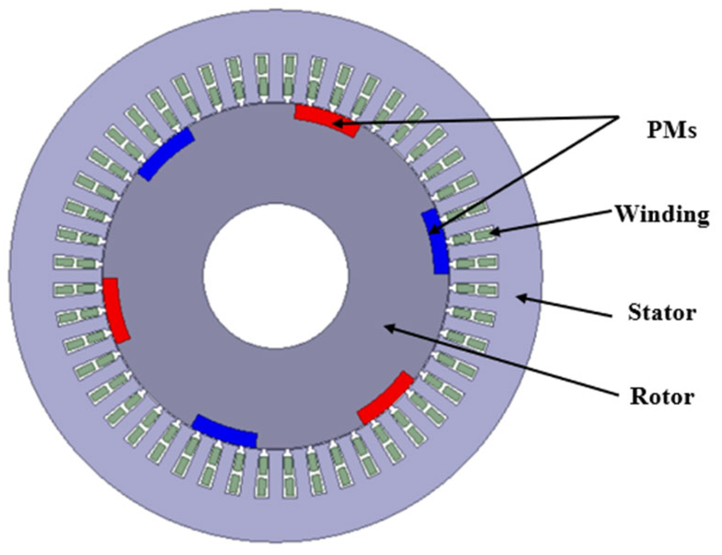
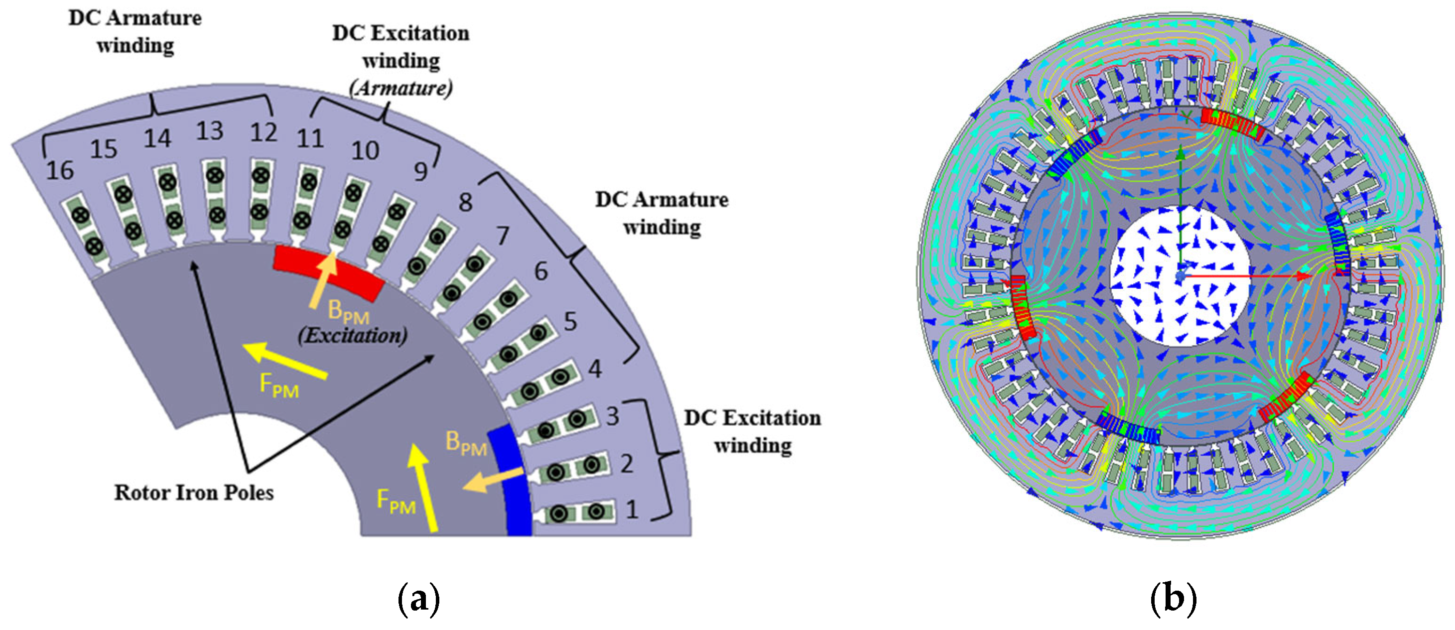
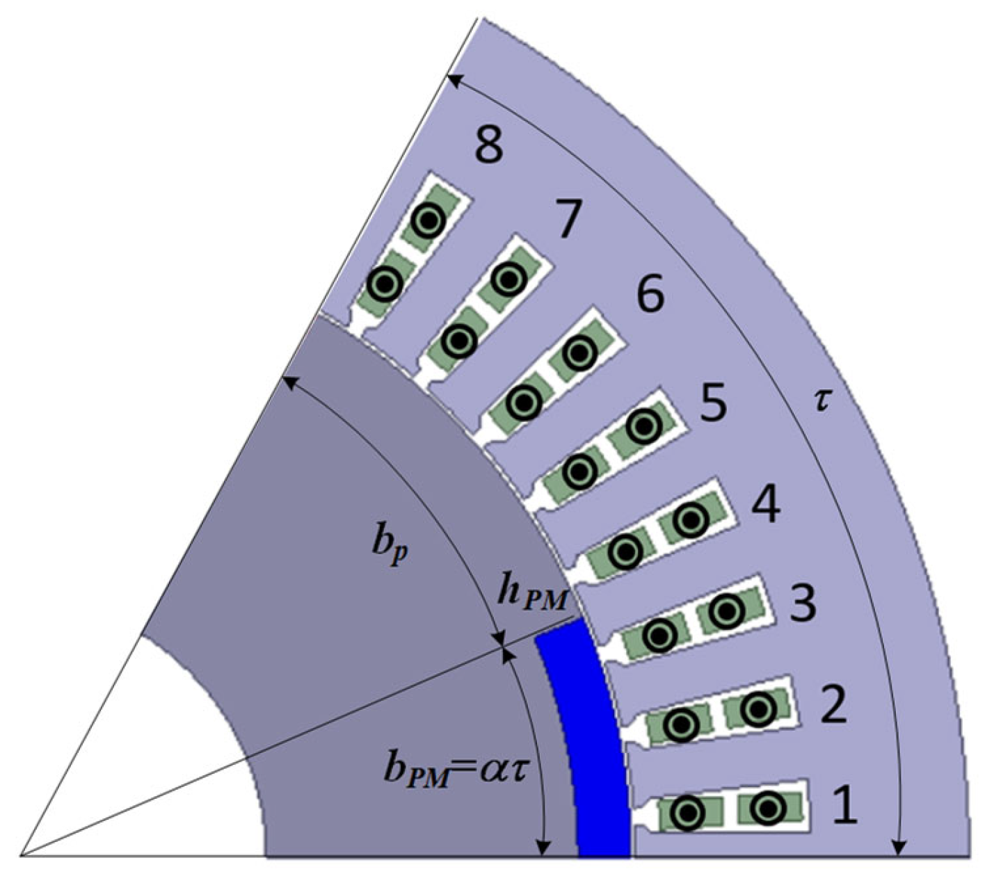
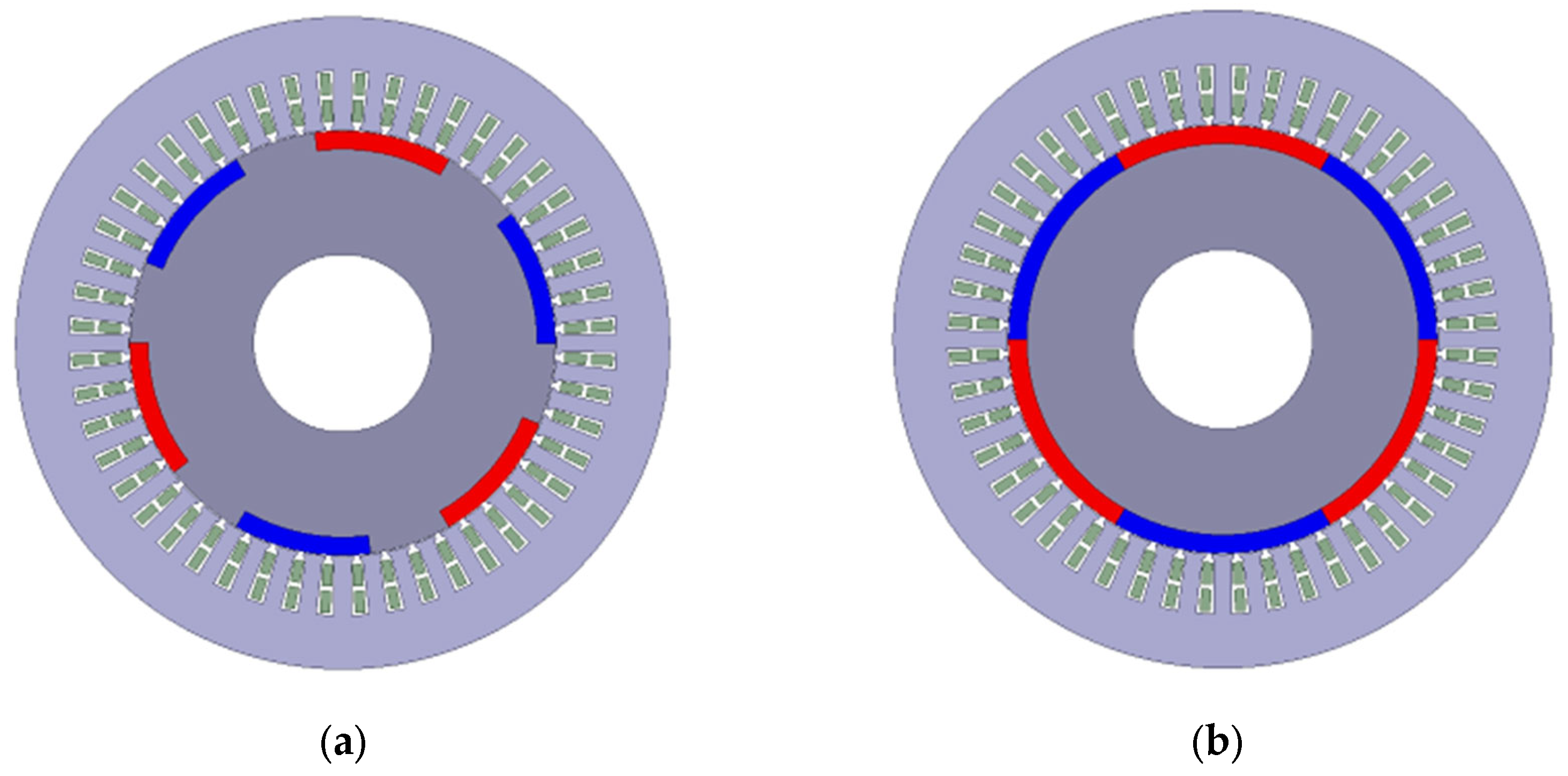
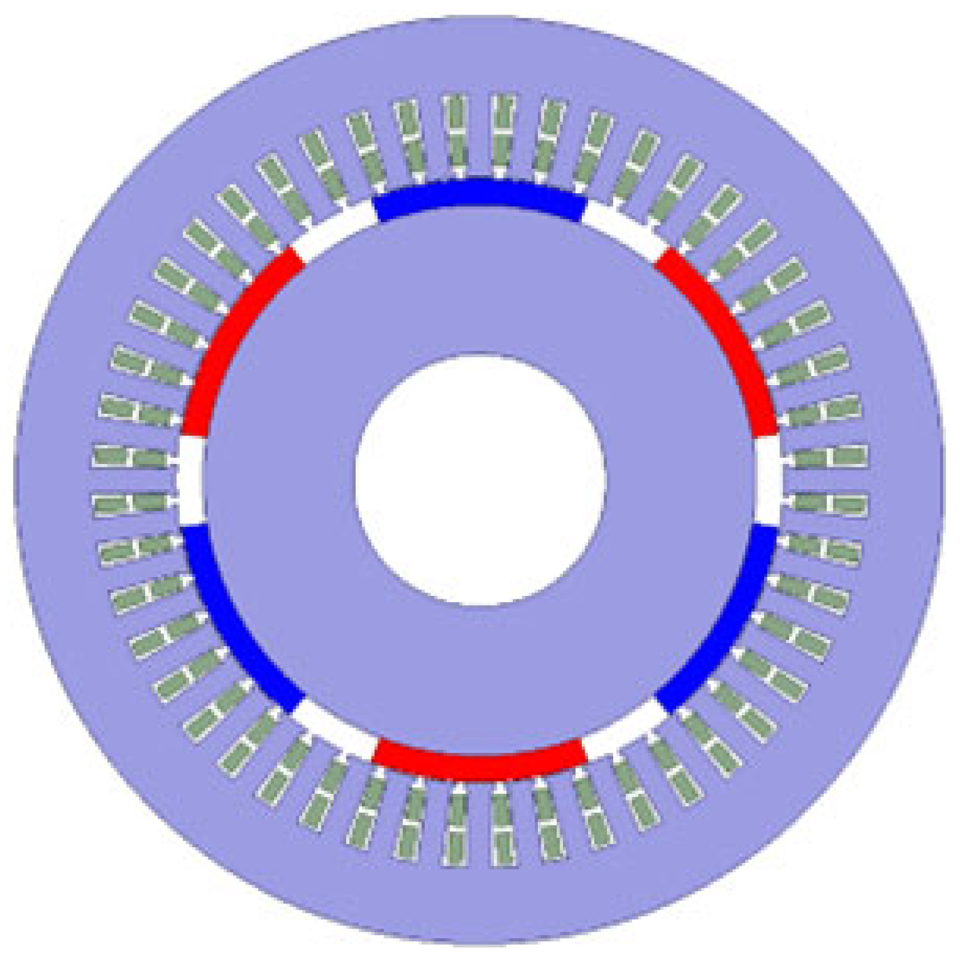
2. Machine Structure

The configuration of PMA-CE-BLDCM is shown in Figure 1. The proposed design has 48 slots, 3 pole-pair assisted PMs, and circular lap winding. Its structure is very similar to a conventional PM synchronous motor. The PMA-CE-BLDCM can be regarded as the combination of a series-excited motor part and a separate-excited motor part. Therefore, the PMA-CE-BLDCM has the characteristics of a compound-excited motor, which is relatively easy to control and has improved flux weakening performance.
The winding connection circuit is shown in Figure 2. The PMA-CE-BLDCM uses controlled power electronic switches to replace the commutator, similar to a typical BLDC motor, which eliminates problems like wear and tear, and sparks. However, the winding of the PMA-CE-BLDCM is connected in series and a polygonal closed-loop, not the opened-loop 3-phase winding of the BLDC motor. This winding design is similar to a regular DC motor, which can be connected to the lap coil or wave coil. The closed-loop winding is simple to analyze and does not require extra electronic devices such as flywheel diodes, etc.
According to the rotor’s position, only two power electronic switches would be activated for every state, allowing the circuit to have two parallel branches, as shown in Figure 3. This enables the power electronic switches to activate less frequently, thus prolonging their operation life. The current direction under the PM poles can be made unchanged by adequately activating the power electronic switches according to the rotor’s position.

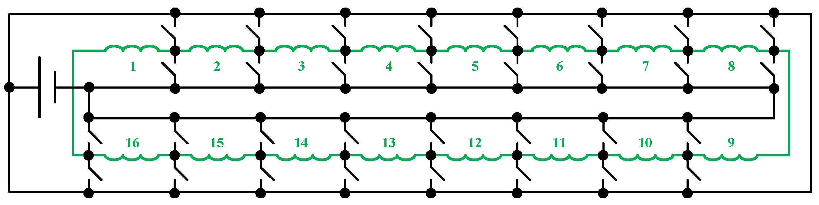
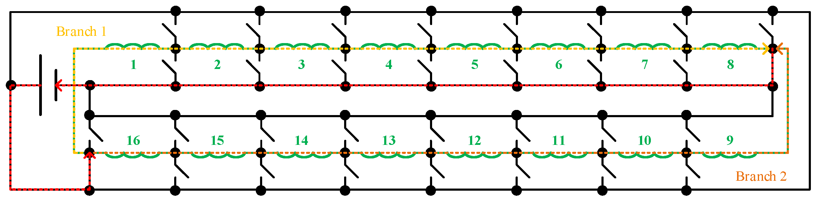
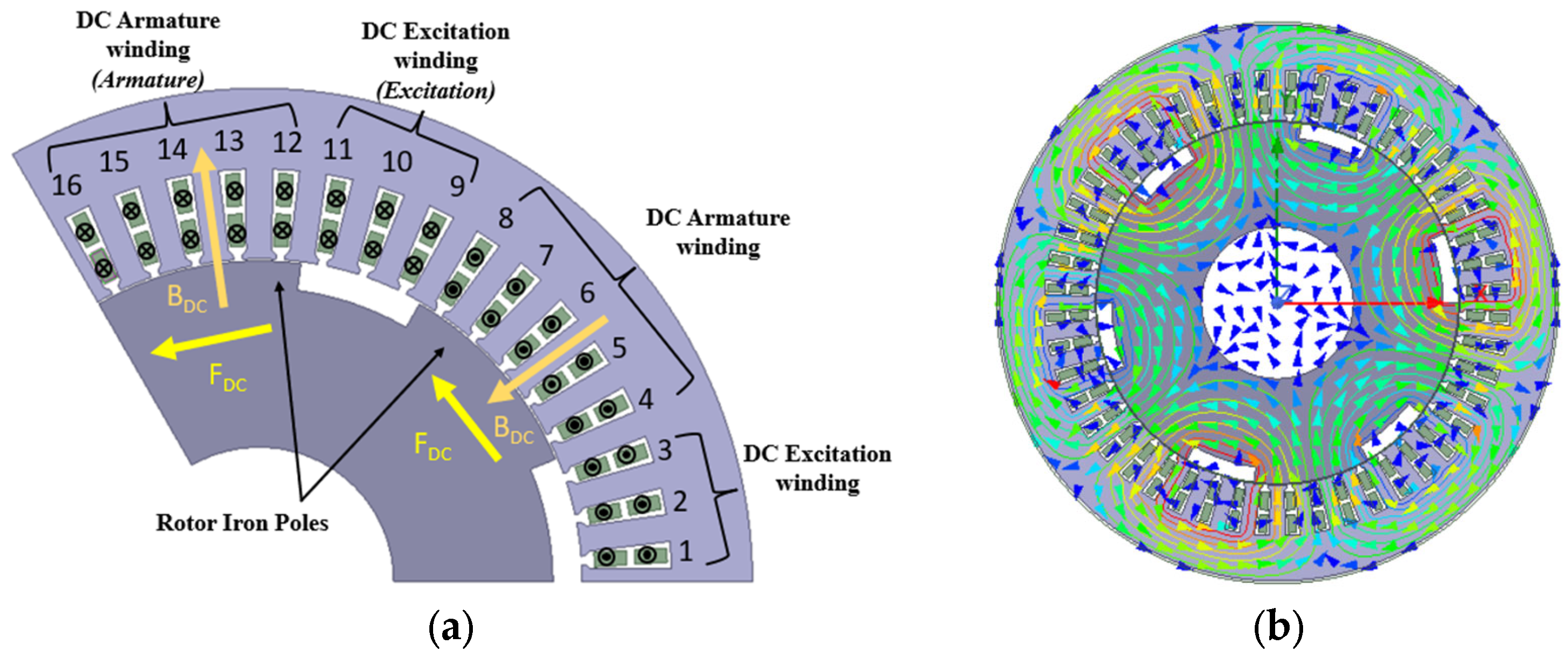
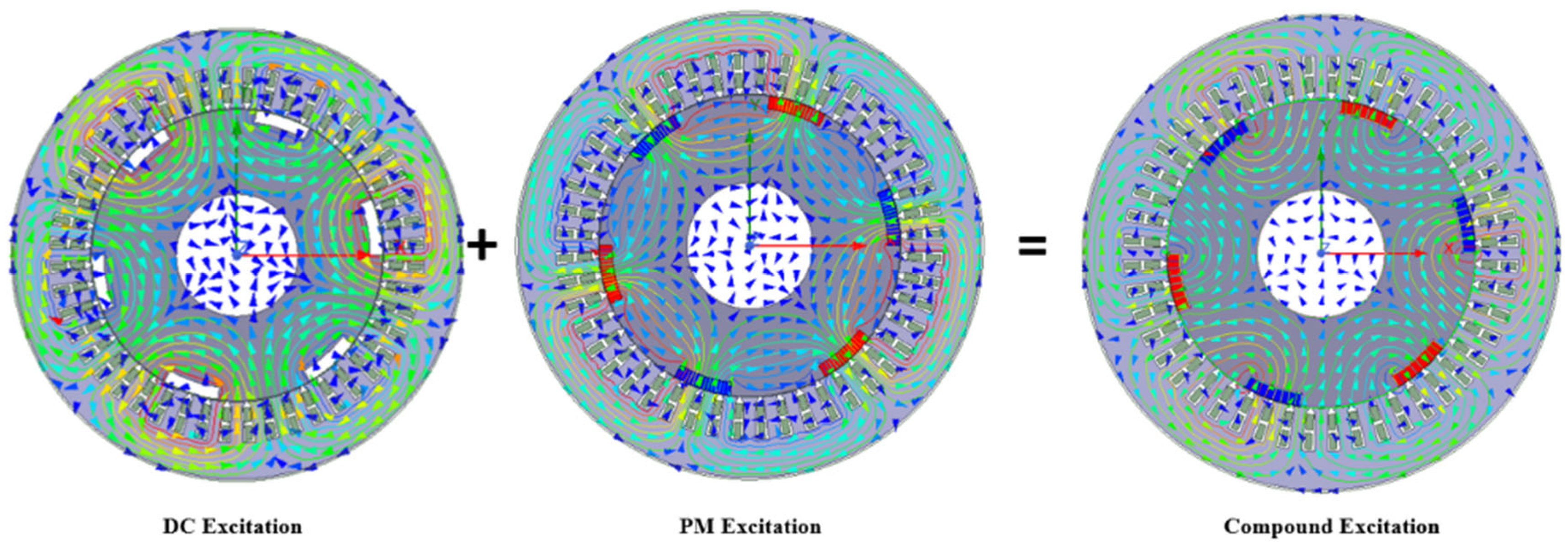
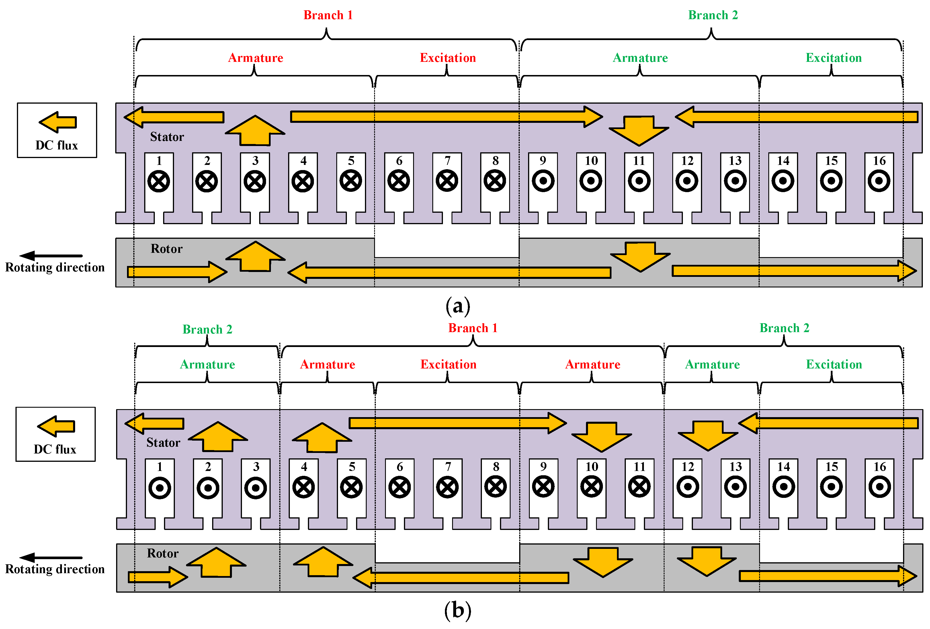
3. Operating Principle

The proposed motor can be considered a combination of a series-excited DC motor and a separate-excited PM machine, explained in the following.
The series-excited DC motor is shown in Figure 4a. Based on the different positions of the rotor, the winding can be divided into two groups: the DC excitation winding, the position of which is between the rotor iron poles; and the DC armature winding, which is under the rotor iron poles. The field is excited by the DC armature winding, i.e., B D C interacts with the DC armature field, causing the rotor to have an anticlockwise electromagnetic force F D C , thus the DC torque is generated. As all the windings are connected in series, the DC excitation winding, the DC armature winding, and the rotor iron poles form a series-excited DC motor. The flux distribution of DC excitation is shown in Figure 4b.
In a series DC motor, the DC excitation winding can only be used for field excitation, which cannot create torque directly. PMs are placed between the rotor iron poles as field excitation sources to further increase the output torque, which allows the DC excitation winding to generate torque. This forms a separate-excited PM motor, which is shown in Figure 5a. The field that is excited by PMs B P M interacts with the DC excitation windings to the generate electromagnetic force F P M and PM torque. Under this configuration, the PMs and the DC excitation winding form a separate-excited DC motor. The flux distribution of PM excitation is shown in Figure 5b.
Therefore, the proposed motor has similar characteristics to a compound-excited motor. The flux distribution of compound excitation in no-load conditions is shown in Figure 6. This makes the PMA-CE-BLDCM easy to control, together with excellent flux weakening performance. Sensorless control can also be applied in the proposed design [9].

4. Analytical Analysis of the PMA-CE-BLDCM

The dimensions of one pole are shown in Figure 7. From Figure 7, the width of the PM b P M , the pole pitch τ , and the embrace of the PM pole α , which is the ratio of angle of the PM to the angle of one pole, can be given as
b P M = α τ
Thus, the width of the iron pole can be expressed as
b p = τ b P M = 1 α τ
The number of conductors in all N can be given as
N = Z N s
where Z is the number of slots and N s is the number of conductors per slot. Therefore, the number of conductors for DC excitation winding N f and the DC armature winding of one branch can be expressed as
N f = α N 2 a
N a = 1 α N 2 a
where a is the pair number of branches. The magnetic resistance of air gap R g and the magnetic resistance of PMs R P M can be given as
R g = g μ 0 b P M l
R P M = h P M μ 0 μ r b P M l
where g is the length of the air gap, μ 0 and μ r are the magnetic permeability of vacuum and ferromagnetic substances, and l is the effective length of the motor. The magnetomotive force (MMF) of PMs can be expressed as
F P M = H c h P M
where H c is the coercivity of PM material and h P M is the thickness of PMs. Neglecting the magnetic resistance of iron, the air gap flux density under the PMs B g P M can be given as
B g P M = Φ P M S P M = F P M R g + R P M S P M = μ 0 μ r H c 1 + μ r g h P M = B r 1 + μ r g h P M
where B r is the remanence of the PM material and S P M is the surface area of one PM. The MMF of DC excitation windings can be expressed as
F D C = N f I
where I is the input current, and the air gap flux density under the iron pole can be given as
B g D C = μ 0 H g D C = μ 0 F D C K c · 2 g = μ 0 N f I K c · 2 g
where K c is Carter’s coefficient, which is related to the slot opening b 0 , stator teeth width t , and air gap length g :
K c = 1 1 b 0 2 5 g + b 0 t
The back EMF induced by PMs and DC excitation will be given as
E P M = N f B g P M l v
E D C = N a B g D C l v
As the diameter of rotor D , line speed v , and the flux passing through the PM poles Φ P M and iron poles Φ D C have the following relationships
π D = 2 p τ
v = 2 p τ n 60
Φ P M = α B g P M l τ
Φ D C = 1 α B g D C l τ
where p is the pole pair number of the PMs, and n is the rotation speed, (13) and (14) can be modified as
E P M = 2 p n 60 N f α α B g P M l τ n = C e Φ P M n
E D C = 2 p n 60 N a 1 α 1 α B g D C l τ n = C e Φ D C n
where C e is the EMF constant which can be expressed as
C e = 2 p 60 N f α = 2 p 60 N a 1 α = p N 60 a
The overall EMF can be expressed as
E = E P M + E D C = C e Φ P M + Φ D C n
The PM torque and the DC torque can be expressed as
T P M = D 2 2 a N f B g P M l I 2 a
T D C = D 2 2 a N a B g D C l I 2 a
Substituting (15), (17), and (18) to (23) and (24), the PM torque and the DC torque can be modified as
T P M = p π N f α Φ P M I = C T Φ P M I
T D C = p π N a 1 α Φ D C I = C T Φ D C I
where C T is the torque constant which can be expressed as
C T = p π N f α = p π N a 1 α = p N 2 π a
Therefore, the overall torque can be expressed as
T = T P M + T D C = C T ( Φ P M + Φ D C ) I

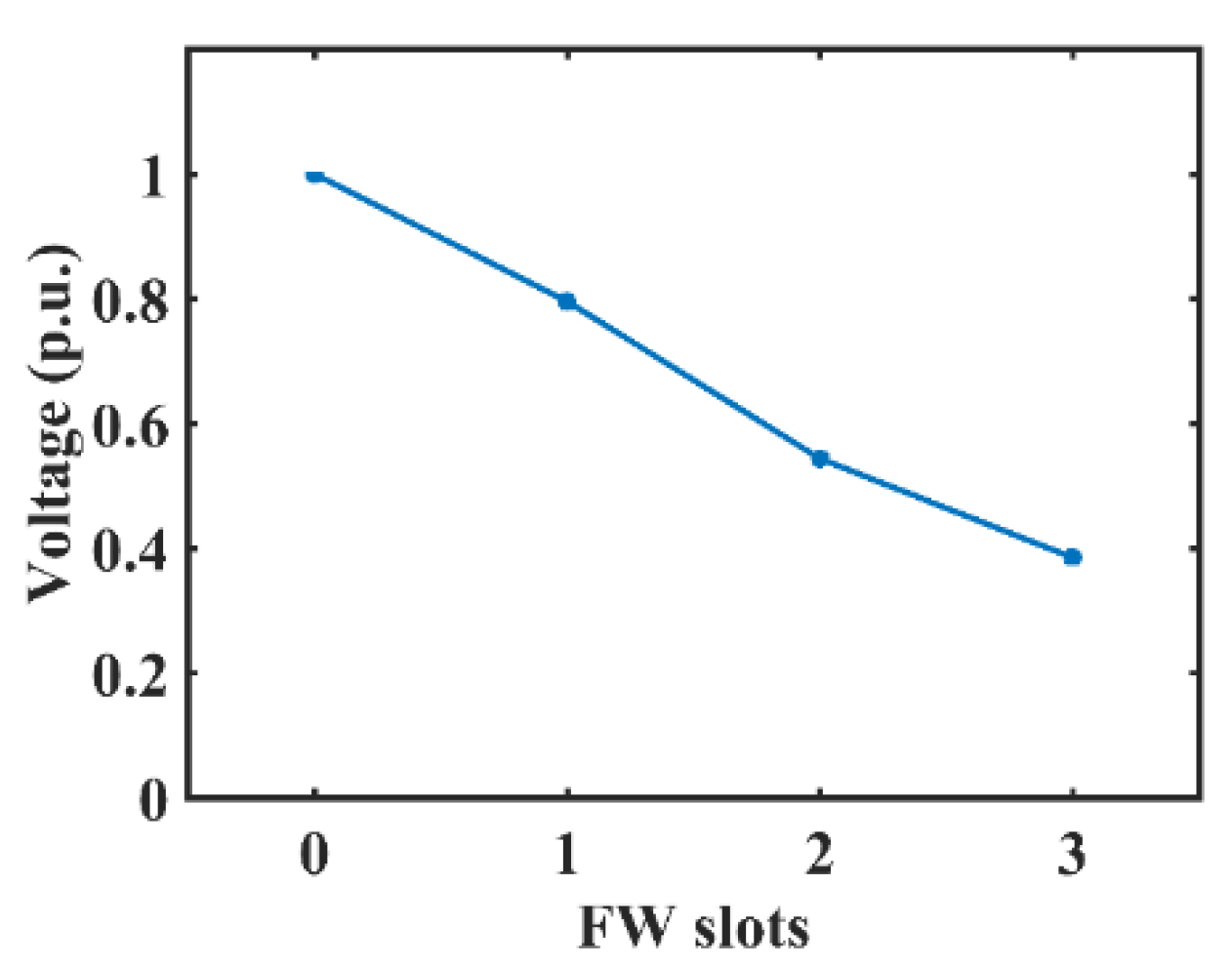
5. Analysis of the Flux Weakening Principle

By making the winding excitation lag several slots behind the rotor’s position, the PMA-CE-BLDCM can be effectively weakened. For the series-excited part of the proposed machine, from Figure 4, because the excitation slot is related to the position of the rotor duct (the duct is the place to put PMs), when the excitation is lagging several slots behind the rotor there are armature slots on both sides of the excitation slots. As the flux directions on both sides are different and the winding is connected in a closed loop, the back EMF of the armature slots on two sides will counterbalance with each other, successfully causing the overall back EMF to decrease, thus achieving flux weakening.
For example, in Figure 8a, all windings of Branch 1 (Slot No.1 to No.8) are in normal status, and have the same magnetic field direction. At this state, the back EMF of each slot is accumulated, and each branch will have the maximum back EMF. In Figure 8b, the winding’s excitation is three slots behind the rotor’s position. In this status, the windings in Slot No. 4 to No. 5 of Branch 1 have a magnetic field in an outward direction, and the windings in Slot No. 9 to No. 11 of Branch 1 have a magnetic field in an inward direction. As the field direction is different, the back EMF induced from Slot No.4 to 5 will counterbalance a certain amount of the EMF generated from Slot No. 9 to 11, making the overall back EMF of Branch 1 decrease, thus achieving flux weakening.
The flux weakening effect on the lagging slots is shown in Figure 9. The field can be weakened to nearly 100% when the motor’s winding is in the lap coil.
The lagging slot method and the method proposed in [8] can both be used for extending speed range in the proposed machine, and the field can be weakened to nearly 100%. However, compared to the switching technique in [8], which decreases the back EMF by decreasing the coil number in the branch through operating four power electronic switches, the proposed lagging slot method only requires two switches, which is half of the number of switches for the method in [8]. Reducing the number of switches can decrease the loss of power switching and prolong the life span of switches and other power electronic devices. Furthermore, the proposed lagging slot flux weakening method can only be used in the proposed machine because the proposed structure contains the brushless series-excited DC motor part, and the winding is connected in a closed loop. The whole process can be achieved by simply controlling the power electronic switches’ operating sequence, which does not acquire extra energy or result in the risk of PM demagnetization.

6. Characteristics of the PMA-CE-BLDCM

By changing the embrace of the PM pole α, the PMA-CE-BLDCM can be categorized into mainly three types of derivatives: DC-excitation dominated, PM-excitation dominated, and whole-PM excited. A proposed α = 3τ/8 model, an α = 5τ/8 model, and an α = τ model are designed. The PM-excitation dominated type and the whole-PM excited type configuration are shown in Figure 10. Apart from the different α, all other dimensions are the same. After using the 2D Finite Element Method (FEM) for analysis, their rotation speed, overall current, and torque (n-I-T) properties are presented in Figure 11. The dimensions of the three designs are shown in Table 1.

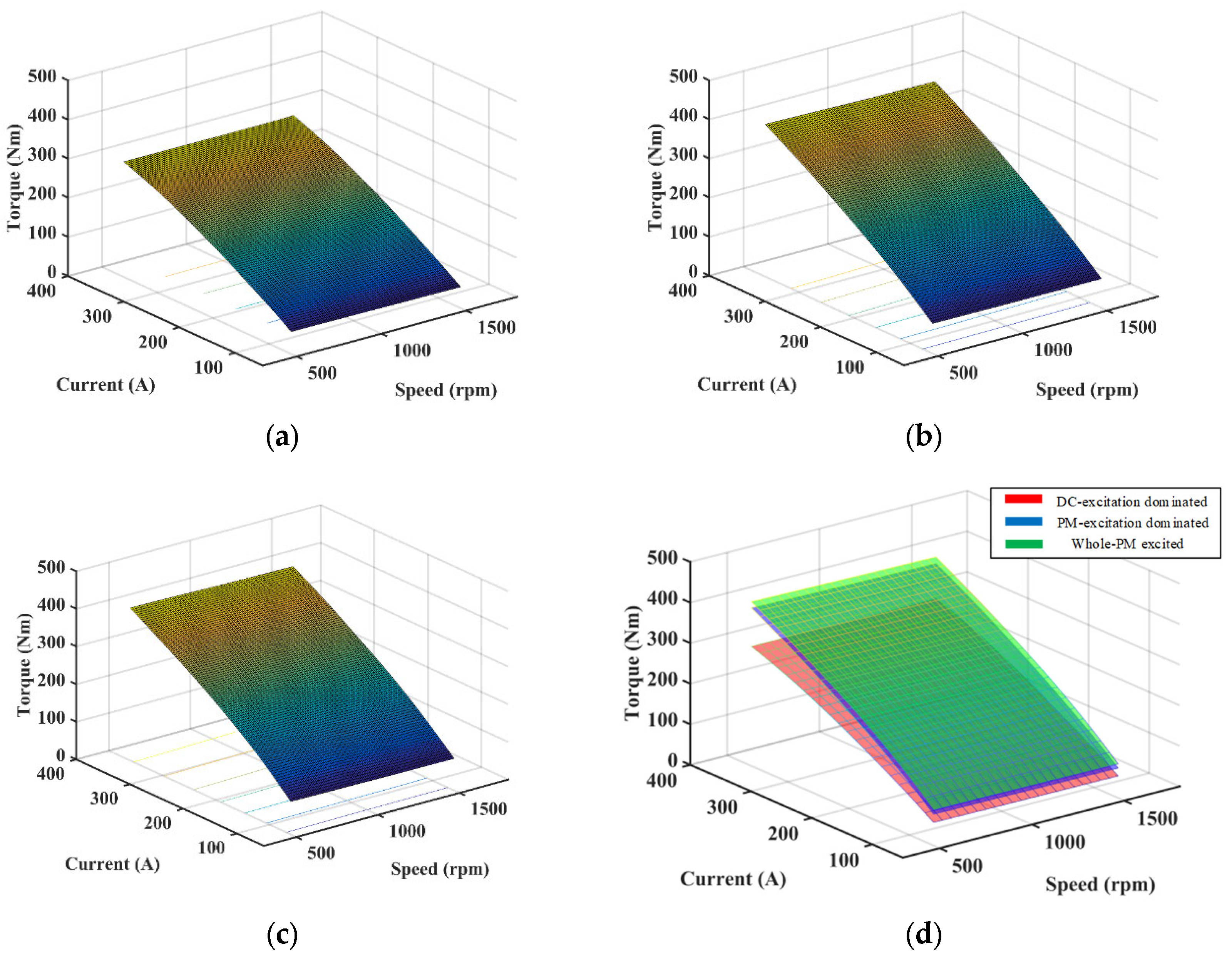
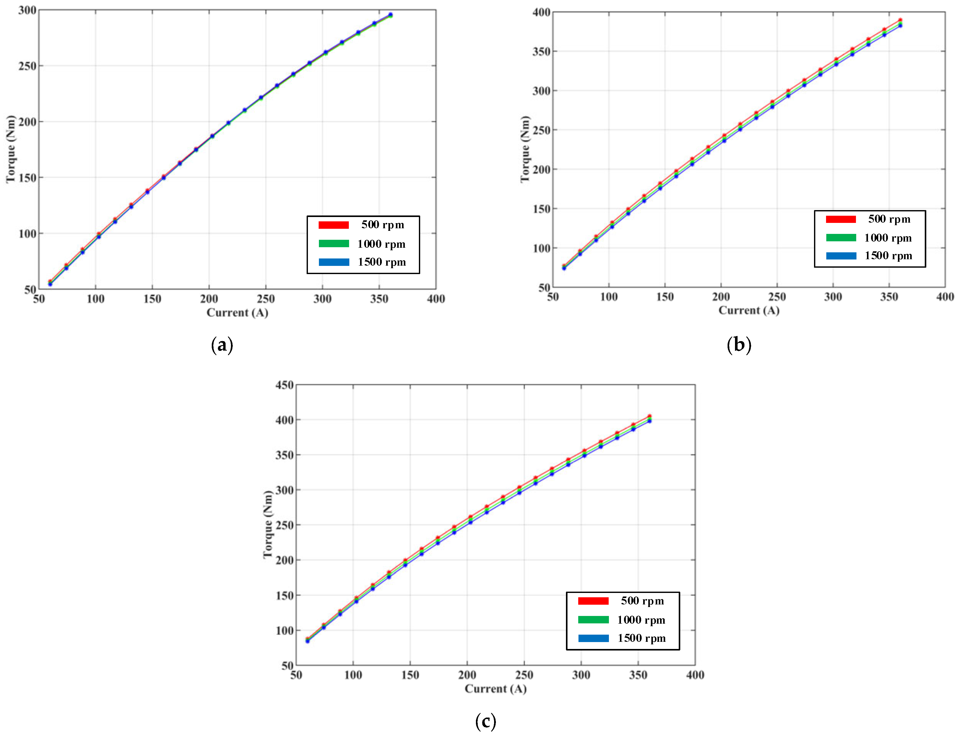
6.1. The Mechanical Characteristics

The mechanical characteristics ( T - n characteristics) are shown on the X-Z plane. All three designs have a minimal slope with a certain input current, the torque of which decreases slightly when speed increases significantly. All three designs’ mechanical characteristics are similar to the compound DC motor. The whole excited type has the highest torque, and the DC-excitation dominated one’s torque is the lowest, about 30% lower than the highest.

6.2. The Regulating Characteristics

The regulating characteristics ( I - n characteristics) are shown on the X-Y plane. All three designs have a similar tendency: the current increases slightly while the speed increases significantly when torque is set. The regulating characteristics of the three designs are quite similar, which shows that all three designs are suitable for applications for a wide speed range.

6.3. The Working Characteristics

The working characteristics ( T - I characteristics) are shown on the Y-Z plane. The torque–current relationship under different speeds for three different types of proposed machine is shown in Figure 12. From Figure 12, it can be observed that the torque–current relationship of the proposed design is almost linear, as the torque increases along with the current, and the relationship remains almost constant regardless of the change of speed.
For a certain speed, the torque increases when the input current is higher. When increasing the current by the same amount, the DC-excitation dominant type’s torque increment is lower than the PM-dominant type, and the PM-excitation dominated type’s torque increment is slightly lower than the whole-PM excited type. For applications where the maximum torque is not required to be much higher than the rated torque, the DC-excitation dominated type is more suitable, as it consumes less PM, and costs less. For applications where load torque varies greatly, the PM-excitation dominated type is recommended.

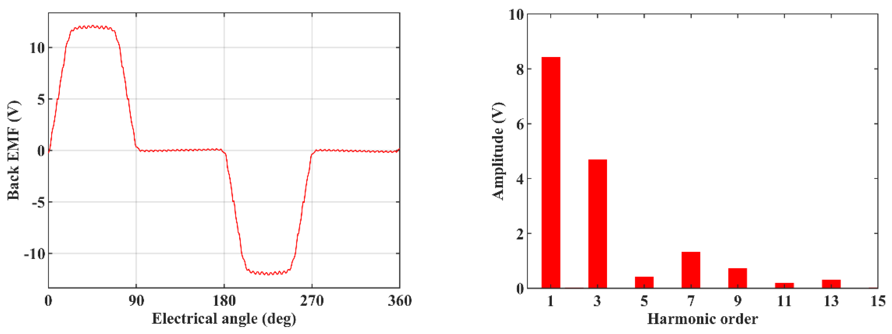
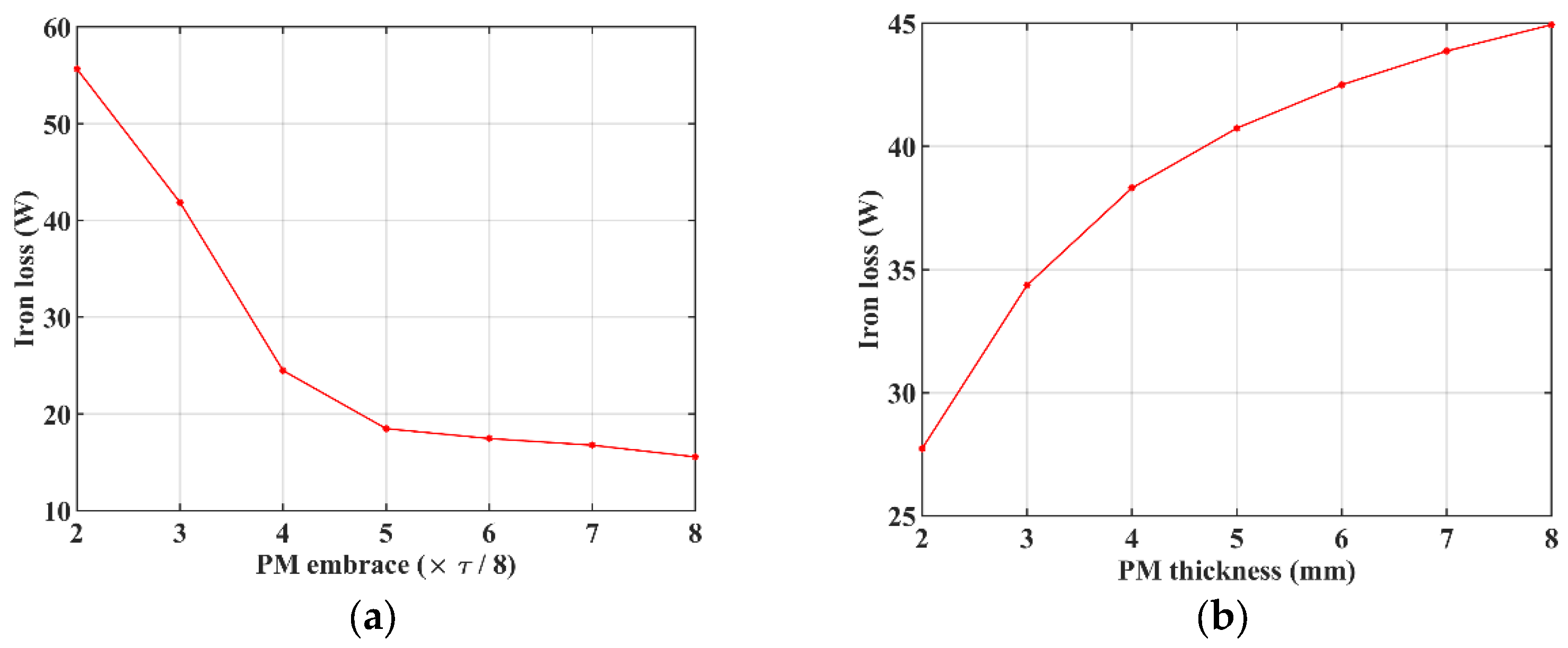
6.4. Back EMF and Iron Loss Analysis

The back EMF curve of winding one and its harmonic analysis is shown in Figure 13. From the harmonic analysis of the back EMF curve, it can be observed that the back EMF of the proposed machine is of trapezoidal shape, which is similar to the characteristic of the conventional brushed DC machine.
For the motor’s architecture, the embrace and the thickness of the PMs are related to the iron loss, and their relationships are shown in the curve form under 500 rpm in Figure 14. As seen in Figure 14a, the iron loss decreases with the increase of PM embrace. The reason is that when the PM embrace is increasing, the ratio of the rotor iron pole decreases, which results in the increase of the magnetic resistance of the DC excitation flux path, thus the iron loss of DC excitation part decreases. As seen in Figure 14b, the iron loss increases when the PM thickness increases, because, according to (8), the magnetomotive force of the PM is related to its thickness.

7. Comparison of Different Designs

When the input current of winding is 90A, and the rotation speed is 500 rpm, the comparison of the three derivates and one BLDC motor’s torque, torque ripple, PM volume, and torque per PM volume are shown in Table 2. All designs have the same dimensions, except for the different PM embrace α . The conventional BLDC motor design is a 3-phase 6-step commutation trapezoidal-wave BLDC motor, shown in Figure 15. The results are presented in Table 2.

7.1. Torque per PM Volume

As the PM material is relatively expensive, how to use a limited volume of PM while maintaining high performance is one of the trends of design for contemporary PM machines. The torque per PM volume is used to quantify the comparison of PM usage. The higher the torque per PM volume is, the more economical the motor is.
Table 2 shows that the DC-excitation dominated type has the highest torque per PM volume, which shows that it is the most cost-effective design. This is because the DC-excitation dominated type has a certain amount of DC excitation. The design with higher PM tends to have lower torque per PM volume.

7.2. Torque Ripple

The torque ripple is also an important index for the motor’s operation. Motors with higher ripple may have problems with noise and instability, which may be unsuitable for high-power applications. From Table 2, the DC-excitation dominated type has the lowest ripple among all designs, which only counts for less than 10% of its overall torque. Designs with higher α , i.e., higher PM consumption tend to have higher torque ripple.
The reason for that is the PMA-CE-BLDCM can be understood as the combination of a series-excited motor and a separate-excited motor, as mentioned previously. For the PMA-CE-BLDCM, the separate-excited PM motor can be considered as a 16-phase 16-step commutation BLDC motor with a stepwise current commutation. For an n-phase BLDC motor, the angle between the rotor magnetic field and stator magnetic field varies (e.g., 60 elec. degrees to 120 elec. degrees for a 3-phase 6-step commutation BLDC motor). Thus, torque ripple is generated. For the series DC motor, all windings are automatically divided into armature windings and excitation windings based on the position of the rotor, whose angle between the rotor magnetic field and stator magnetic field is always 90 elec. degrees, thus no torque ripple will be generated.
Therefore, the higher α is, the higher proportion of the separate-excited PM motor the design has, and thus the higher the torque ripple the overall design will experience.

8. Conclusions

A novel PMA-CE-BLDCM is proposed in this paper. The proposed machine has the following merits:
i.
High torque per PM volume: As PM material is, relatively, the most expensive part in current machine manufacturing costs, the PMA-CE-BLDCM uses DC excitation along with the PM excitation, which greatly reduces the use of PM while keeping the performance unchanged, compared to the whole-PM excited machine. Its torque per PM volume is higher than the conventional BLDC motors’.
ii.
Simple and easy speed regulation: For the constant-torque region, because the PMA-CE-BLDCM is a DC motor, its controlling method is much simpler than the AC motors, which only need to regulate the input voltage. For the constant-power region, the PMA-CE-BLDCM also has the merit of a simple and advantageous flux weakening ability, which allows the motor to increase its speed range. By controlling the lagging slots of the winding excitation behind the rotor’s position, the flux weakening of the proposed machine can be smoothly achieved to near 100%.
iii.
Full use of windings and good torque-speed characteristics: The PMA-CE-BLDCM uses DC-excited and PM-excited sources to fully use all the windings. It has the characteristics of a compound-excited motor.
iv.
Simple manufacturing: The PMA-CE-BLDCM’s structure is almost the same as an SPM type PMSM (also can be modified to interior PM type), whose manufacturing procedure is highly developed.
A 2D-FEM model of the proposed design has been built. Its characteristics have been analyzed and compared with other similar BLDCMs. The results show that the proposed design has the lowest torque ripple and the highest torque per PM volume.

Author Contributions

M.J.: investigation, methodology, writing—original draft preparation. K.Z.: simulation and editing. S.N.: supervision, writing—review and editing, project administration, funding acquisition. W.W.: writing—review and editing. All authors have read and agreed to the published version of the manuscript.

Funding

This research was funded by the Hong Kong Research Grants Council, Hong Kong, under Project PolyU 152109/20E.

Institutional Review Board Statement

Not applicable.

Informed Consent Statement

Not applicable.

Data Availability Statement

Not applicable.

Conflicts of Interest

The authors declare no conflict of interest.

References

  1. Fitzgerald, A.E.; Kingsiey, C., Jr.; Umans, S.D. Electric Machinery, 6th ed.; McGraw-Hill: New York, NY, USA, 2002. [Google Scholar]
  2. Tang, Y.; Shi, N. Electric Machinery, 2nd ed.; China Machine Press: Beijing, China, 2008. [Google Scholar]
  3. Miller, T.J.E. Brushless Permanent-Magnet and Reluctance Motor Drives; Oxford University Press: New York, NY, USA, 1989. [Google Scholar]
  4. Gieras, J.F.; Wing, M. Permanent Magnet Motor Technology: Design and Applications; Marcel Dekker: New York, NY, USA, 2002. [Google Scholar]
  5. Gan, J.; Chau, K.T.; Chan, C.C.; Jiang, J.Z. A new surface-inset, permanent-magnet, brushless DC motor drive for electric vehicles. IEEE Trans. Magn. 2000, 36, 3810–3818. [Google Scholar]
  6. Wang, Y.; Chau, K.T.; Gan, J.; Chan, C.C.; Jiang, J.Z. Design and analysis of a new multiphase polygonal-winding permanent-magnet brushless DC machine. IEEE Trans. Magn. 2002, 38, 3258–3260. [Google Scholar] [CrossRef]
  7. Zhu, L.; Jiang, S.Z.; Jiang, J.Z.; Zhu, Z.Q.; Chan, C.C. A New Simplex Wave Winding Permanent-Magnet Brushless DC Machine. IEEE Trans. Magn. 2011, 47, 252–259. [Google Scholar] [CrossRef]
  8. Zhu, L.; Jiang, S.Z.; Jiang, J.Z.; Zhu, Z.Q.; Chan, C.C. Speed Range Extension for Simplex Wave Winding Permanent-Magnet Brushless DC Machine. IEEE Trans. Magn. 2013, 49, 890–897. [Google Scholar] [CrossRef]
  9. Jia, Z.; Zhang, Q.; Wang, D. A Sensorless Control Algorithm for the Circular Winding Brushless DC Motor Based on Phase Voltages and DC Current Detection. IEEE Trans. Ind. Electron. 2021, 68, 9174–9184. [Google Scholar] [CrossRef]
Figure 1. The configuration of PMA-CE-BLDCM.
Sustainability 15 13924 g001
Figure 2. Winding connection circuit of PMA-CE-BLDCM.
Sustainability 15 13924 g002
Figure 3. Current flowing status of one switching state with the polygonal closed-loop circular winding.
Sustainability 15 13924 g003
Figure 4. Series-excited DC motor part. (a) Display diagram. (b) Flux distribution.
Sustainability 15 13924 g004
Figure 5. Separate-excited PM motor part. (a) Display diagram. (b) Flux distribution.
Sustainability 15 13924 g005
Figure 6. Flux distribution of the compound excitation.
Sustainability 15 13924 g006
Figure 7. Dimensions of one pole.
Sustainability 15 13924 g007
Figure 8. Diagram of lagging slot flux weakening method. (a) Normal status. (b) Three-slot lagging flux weakening mode.
Sustainability 15 13924 g008
Figure 9. The voltage per unit to flux weakening slots waveform with the circular winding.
Sustainability 15 13924 g009
Figure 10. Configuration of the PMA-CE-BLDCM derivatives. (a) PM-excitation dominated ( α = 5 τ / 8 ). (b) Whole-PM excited type ( α = τ ).
Sustainability 15 13924 g010
Figure 11. n - I - T characteristics of different types of PMA-CE-BLDCM. (a) DC-excitation dominated type ( α = 3 τ / 8 ). (b) PM-excitation dominated type ( α = 5 τ / 8 ). (c) Whole-PM excited type ( α = τ ). (d) Comparison of all three types.
Sustainability 15 13924 g011
Figure 12. The torque–current relationship under different speeds. (a) DC-excitation dominated type. (b) PM-excitation dominated type. (c) Whole-PM excited type.
Sustainability 15 13924 g012
Figure 13. The back EMF curve and its harmonic analysis of winding one.
Sustainability 15 13924 g013
Figure 14. The impact of structural parameters on iron loss. (a) PM embrace to iron loss. (b) PM thickness to iron loss.
Sustainability 15 13924 g014
Figure 15. Configuration of the 3-phase 6-step commutation trapezoidal-wave conventional BLDC motor.
Sustainability 15 13924 g015
Table 1. Dimensions of Three Different Designs.
ItemValue
DC-DominatedPM-DominatedWhole-PM
Stator outer diameter220 mm
Stator inner diameter144 mm
Airgap length0.5 mm
Axial length135 mm
Pole pair number3
Slot number48
Thickness of PM6 mm
Embrace of PM 3 8 τ 5 8 τ τ
Rated voltage47 V62 V81 V
Table 2. Comparison of Three Different Designs and a BLDC motor.
Designs α T T r i p p l e V P M T / V P M
The PMA-CE-BLDCM derivativesDC-excitation dominated 3 8 τ 168 Nm14.03 Nm 1.31   ×   10−4 m3 1.28   ×   106 Nm/m3
PM-excitation dominated 5 8 τ 219 Nm67.83 Nm 2.18   ×   10−4 m3 1.00   ×   106 Nm/m3
Whole-PM
excited
τ 238 Nm71.03 Nm 3.49   ×   10−4 m3 0.68   ×   106 Nm/m3
Conventional BLDC motor 7 10 τ 192 Nm62.53 Nm 2.44   ×   10−4 m3 0.79   ×   106 Nm/m3
Disclaimer/Publisher’s Note: The statements, opinions and data contained in all publications are solely those of the individual author(s) and contributor(s) and not of MDPI and/or the editor(s). MDPI and/or the editor(s) disclaim responsibility for any injury to people or property resulting from any ideas, methods, instructions or products referred to in the content.

