Article

Research on Gas Recycling of Free-Piston Expander–Linear Generator for Organic Rankine Cycle of Vehicle

School of Electrical and Mechanical Engineering, Beijing Information Science and Technology University, Beijing 100192, China
*
Author to whom correspondence should be addressed.
Sustainability 2023, 15(18), 13993; https://doi.org/10.3390/su151813993
Submission received: 14 July 2023 / Revised: 30 August 2023 / Accepted: 14 September 2023 / Published: 21 September 2023

Abstract

:
A (FPE-LG) is a new type of vehicle waste heat recovery device based on an organic Rankine cycle. It is expected to achieve the reuse of vehicle internal combustion engine waste heat and improve the comprehensive utilization rate of energy. To enable the FPE-LG to recover exhaust gas to a greater extent in practical applications, based on the FPE-LG coupling gas storage tank test platform, the gas is discharged from the expander cylinder. This paper analyzes the influence of differences to the tank volume, intake pressure, intake duration time, expansion duration time and exhaust duration time on piston motion characteristics and gas storage and release time during the cycle, and verifies the feasibility of gas working as a recycling medium. The results showed that the energy storage of lithium batteries increases with the increase of intake pressure, and the energy stored in lithium batteries during gas release is higher than that during gas storage; the intake duration time, expansion duration time and exhaust duration time have little effect on the storage of lithium battery energy during the cycle. When the intake pressure is 0.5 MPa, the volume of the gas tank is 30 L, and the intake duration time, expansion duration time and exhaust duration time are 50 ms, 80 ms and 30 ms, respectively, the maximum actual stroke of the piston can reach 89.592 mm.

1. Introduction

The organic Rankine cycle (ORC) has been successfully applied to the recovery of industrial waste heat for power generation. At the same time, the ORC system is used to recover the waste heat of internal combustion engines, which is considered an effective way to alleviate the energy crisis and reduce environmental pollution. As a key component of the ORC system, a free-piston expander (FPE) eliminates the crank connecting rod mechanism and has the advantages of compact structure, fewer parts and light weight, making it suitable for automotive use. A linear generator (LG) has the characteristics of simple structure, good transient response characteristics and high control accuracy. Therefore, as a new hybrid power device, the FPE-LG is more suitable for applications in the automotive field and has many potential performance advantages, which have been studied by many research institutions.

1.1. Application Status of Organic Rankine Cycle

The organic Rankine cycle (ORC) system mainly makes effective use of low temperature heat sources, replacing the circulating working medium of the traditional Rankine cycle with organic working medium, while the rest of the components and the cycle processes remain unchanged. The organic working medium is used to perform the cycle heat transfer work in the system. Many scholars have studied the selection of an ORC working medium and the efficiency of the system [1,2,3]. The ORC system has higher efficiency and a relatively simple structure, which can effectively reduce internal combustion engine fuel consumption and vehicle pollutant emissions. This provides technical and theoretical support for the recovery of waste heat from internal combustion engines, the improvement of energy utilization efficiency, and the achievement of energy conservation and emission reduction. At present, the ORC technology has been successfully applied to the waste heat recovery in the stationary power generation industry. The Catapano team has studied an advanced energy system that can be used for power production and heat storage, which improves the overall efficiency of ships by recovering the heat wasted by the propulsion system. The research on this device will greatly improve the thermodynamic, economic, and environmental results of future clean ships [4]. ORI MARTIN Iron and Steel Plant installed a large ORC unit and a waste heat recovery unit. This device recovers waste heat from the flue gas of the Electric Arc Furnace (EAF), generates saturated steam, and is then transported to the regional heating network during the heating season, and to the ORC for power generation during the rest of the year [5]. The National Technical University of Athens, in collaboration with Winterthur Gas & Diesel, has developed an innovative low-pressure exhaust gas recirculation unit for low-speed two-stroke Marine propulsion, combining the ORC system with an abatement system to meet stringent emission requirements while increasing overall system efficiency and reducing NOx emissions [6].

1.2. Research Status of Free-Piston Expander Linear Generator

At present, organic Rankine cycle technology is mostly used for industrial waste heat recovery, and its application in the automotive field is still in the research and development stage. C. Champagne et al. conducted a preliminary experimental analysis of a small free-piston expander (FPE) [7]. Preetham et al. designed a small free-piston expander engine that utilizes a low-temperature heat source to output effective power. The results indicate that the performance of a free-piston expander depends on the piston mass, external load, heat input rate and heat input power [8]. Bouvier et al. conducted an experimental study on a steam piston expander without lubricating oil, and the experimental results provided a reference for the expander to be integrated into the ORC [9]. Burugupally et al. studied a micro-free-piston expander with the potential to collect low-temperature waste heat. Research has shown that a centimeter-sized expander can generate an output power of 2.24 W at an efficiency of 18% [10]. Wang et al. used the concept of a free-piston engine to construct an experimental test bench for a free-piston expander. The results indicate that increasing the driving pressure can effectively improve the energy conversion efficiency [11]. Wu et al. proposed a single piston free-piston expander using compressed air as the working fluid for a linear generator testing system for power conversion. The effects of intake time and intake pressure on the performance of the testing system were studied, and the nominal power electricity conversion loss coefficient was proposed for the first time to represent the energy loss [12,13]. Xu et al. [14] developed an FPE-LG experimental bench and established a simulation model using Matlab/Simulink. On the basis of experiments, its motion characteristics and output performance were discussed, and the simulation model was validated. S. Gusev et al. describe a dynamic model of a novel free-piston expander with variable built-in volume ratio (BVR) for organic Rankine cycle (ORC) applications. In order to prove the feasibility of the proposed concept and verify the theoretical model, a test device was designed and built [15]. Tian Yaming et al. discussed the effects of inlet pressure, operating frequency and external load resistance on the operating characteristics and output performance of free-piston linear generators. The results show that the peak speed can reach 0.69 m/s and the maximum output power is 96 W. When the operating frequency is 2.0 Hz and the inlet pressure is 2.6 bar, the energy conversion efficiency of the free-piston linear generator is 45.82%. The influence of the opening time of intake and exhaust valves on the output performance of FPE-LG was studied [16,17]. Li Gaosheng et al. proposed the FPE-LG integrated system combined with the organic Rankine circulation system, and analyzed the dynamic characteristics of the flow field in the cylinder through fluid mechanics. The results show that the indicated efficiency of FPE reaches 66% and the maximum output power is 22.7 W [18]. Xu et al. studied the cylinder pressure, motion characteristics, and output performance of FPE-LG with different valve timing, and analyzed the influence of external load resistance on the motion characteristics and output performance of cam A plate. The results indicate that the intake duration and exhaust duration have a significant impact on the motion characteristics and output performance of FPE-LG [19]. Xu Yongming et al. studied the relationship and influence among reciprocating motion, friction force, cylinder process and electromagnetic characteristics of a permanent magnet linear generator, and determined the intake pressure and position of the linear generator at its highest efficiency [20]. In order to improve the compactness of the expander, Gao Jianbing et al. proposed an opposed rotary piston expander, and analyzed the performance of the expander through 3D numerical simulation [21]. Burugupally et al. investigated the influence of working fluid characteristics on an expansion unit based on free-piston (FPE) architecture. The research results show that in order to obtain a higher FPE efficiency, the working fluid needs to have a higher specific heat ratio [22]. A. Rashid et al. studied the influence of different generator stator cores and generator structures on system motion characteristics, stability and efficiency [23]. Mhadi A. Ismael et al. developed a free-piston linear generator experimental bench to study piston motion, RMS output power, operating frequency, system stability, system performance and conversion efficiency under different intake pressures and valve open times (VOD) [24]. Guo et al. developed a linear power device, a free-piston gasoline engine linear generator, which coupled a linear internal combustion engine with a linear generator, and studied the effects of combustion parameters, ignition timing and combustion efficiency on the engine performance of the device [25]. Yu Song et al. proposed two control strategies of displacement signal and velocity signal, and analyzed that the velocity trigger strategy is more suitable for the starting process of free-piston linear generator [26]. Xin Shi et al. analyzed the stability of free-piston assembly based on a displacement control strategy [27].
It can be seen that previous studies mostly focused on the prototype development of a free-piston expander–linear generator, system performance, output performance and control strategy; however, there were few studies on the utilization of a working medium gas. After the gas enters the expander for expansion, part of the gas is still discharged from the expander exhaust valve to the outside. In this paper, a free-piston expander–linear generator coupled with the gas storage tank is built. The gas discharged from the expander exhaust valve is stored by the gas storage tank and then re-enters the cylinder to generate electric energy, thus realizing the recycling of the gas and further reducing gas emissions. The effects of different tank volumes, intake pressures, intake duration times, expansion duration times and exhaust duration times on gas storage and the release process in one cycle were studied.

2. FPE-LG Test Bench

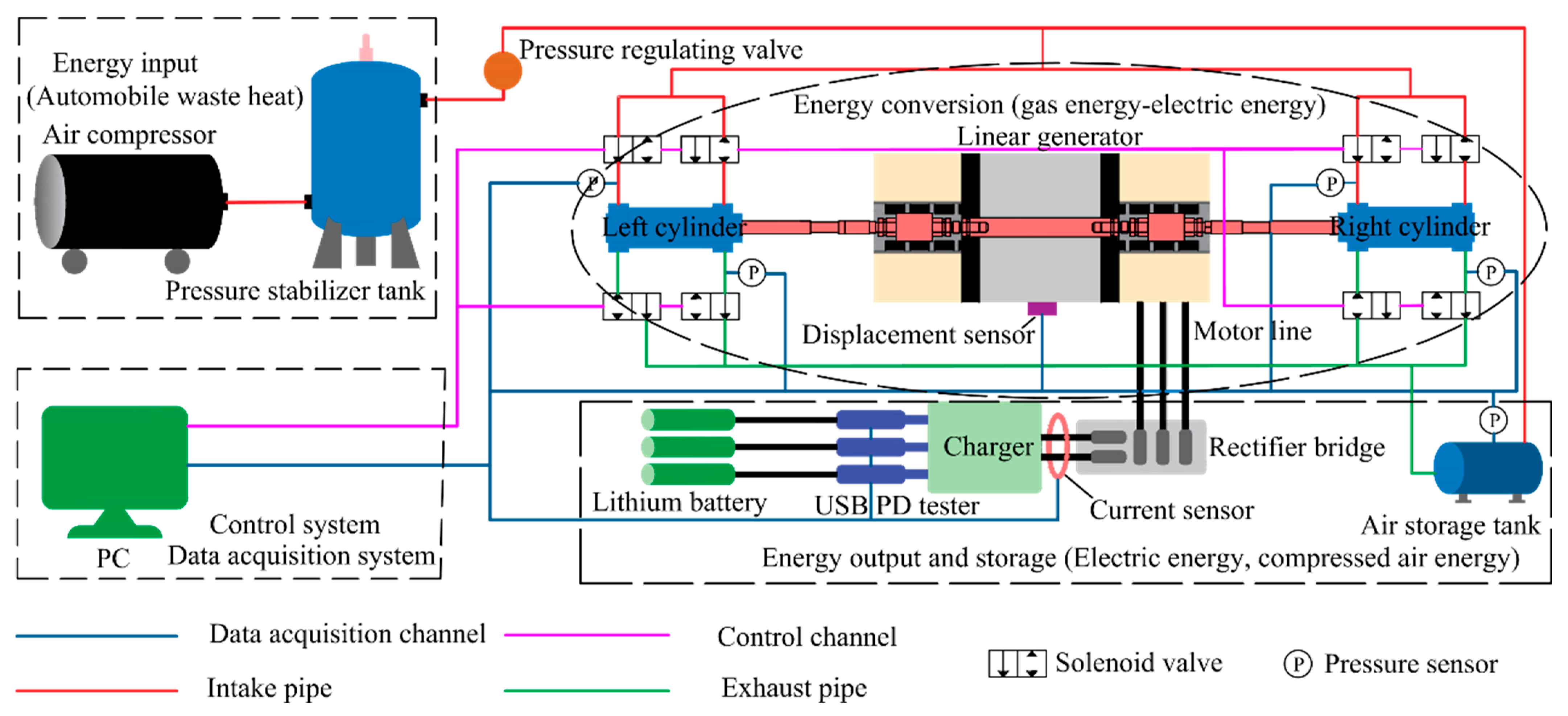
Figure 1 shows the FPE-LG test bench. The test bench consists of a free-piston expander (FPE), a linear generator (LG), an air compressor, a pressure regulator, a pressure regulating valve, a solenoid valve, various sensors, a three-phase rectifier, a charger, a USB PD tester, a lithium battery, an air storage tank and a data acquisition system. The air compressor serves as the power source to generate compressed air, and the pressure stabilizing tank plays a stabilizing role. The pressure regulating valve controls the pressure of the gas entering the cylinder of the expander, the electromagnetic valve controls the intake and exhaust processes of the free-piston expander, and the air storage tank is used to collect unused gas discharged from the cylinder of the expander. A pressure sensor is used to measure the pressure change inside the air storage tank, and a displacement sensor is used to measure the displacement of the piston inside the expander cylinder. The parameters of each component are shown in Table 1.
The overall structure of the test bench includes four parts: energy input, energy conversion, energy output, storage and control system and data acquisition system. Energy input part: the compressed air generated by the air compressor enters the system with stable and pressurized compressed gas through a pressure regulating tank and pressure regulating valve. Energy conversion part: the cylinder of FPE converts the energy of compressed gas into the kinetic energy of the piston. The piston-connecting rod is connected to the linear generator rotor, and the movement of the piston drives the linear generator rotor to cut the magnetic induction line and generate a three-phase alternating current, thereby achieving the conversion from compressed gas energy to electrical energy. Energy output part: the three-phase AC power output by the linear generator is rectified, and the lithium battery is charged through a charger to store the output electrical energy. The exhaust channel is connected to the gas storage tank, and the gas discharged from the expander is collected into the gas storage tank. The unused gas during the energy conversion process is stored again in the form of compressed gas, achieving energy recycling. Control system and data acquisition system: The intake and exhaust processes of the expander are controlled by controlling the opening and closing of the intake and exhaust solenoid valves, thereby controlling the movement of the piston. Collect, analyze and save relevant data through the data acquisition system. Figure 2 shows the schematic diagram of the FPE-LG test bench.
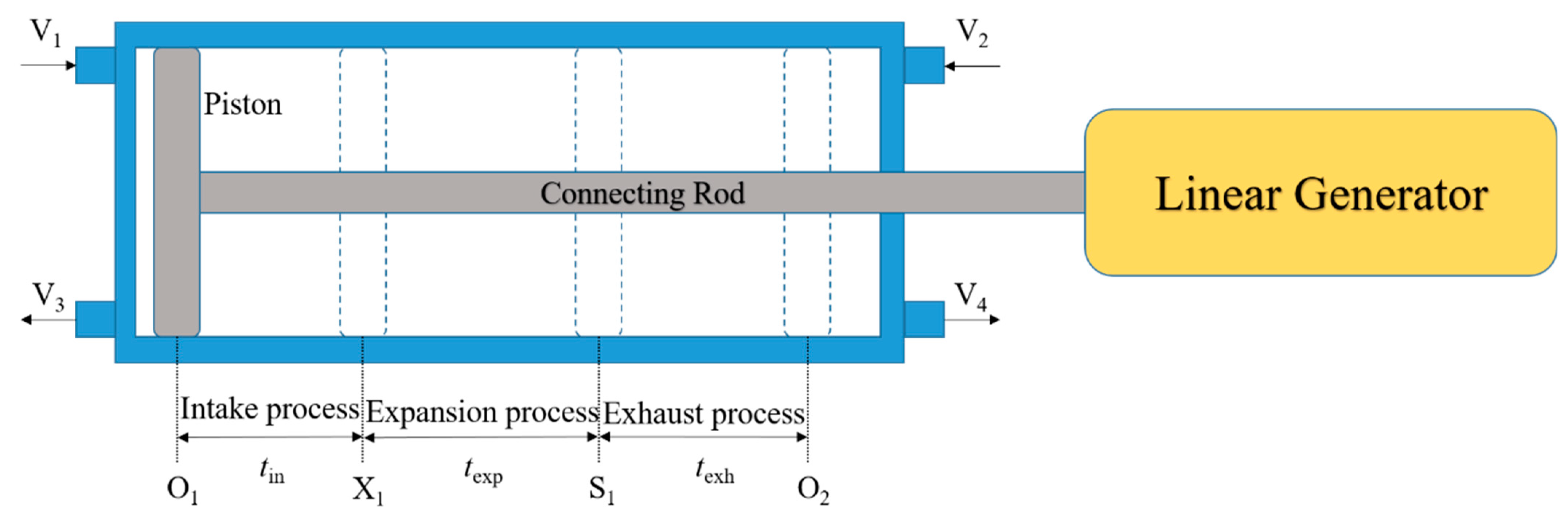
Taking the working process of the free-piston in the left cylinder of the expander as an example, the working principle of FPE-LG is explained, as shown in Figure 3. The solenoid valves V1, V2, V3 and V4 are used to control the intake and exhaust processes of the expander cylinder. When FPE-LG operates, the leftmost position O1 that the free-piston assembly can reach is called the working top dead center (OTDC), and the rightmost position O2 is called the working bottom dead center (OBDC) [21]. The movement of the free-piston from left to right is divided into three processes: intake, expansion and exhaust. The intake duration is tin, the expansion duration is texp, and the exhaust duration is texh. The time of the three processes is controlled by controlling the opening and closing of the solenoid valve, and the opening and closing states of the solenoid valves in each process are shown in Table 2. The solenoid valves V1 and V4 are in the open state during the intake process, and the free-piston moves to X1 after passing the intake duration tin. At this point, the intake process is completed. During the expansion process, all solenoid valves are closed, and the gas expands again in the cylinder of the expansion machine. The free-piston continues to move to the right to S1 after a duration of texp, and the expansion process is completed. During the exhaust process, solenoid valve V4 opens, and the free-piston continues to move to the right to O2 after a duration of texh, completing the exhaust process. The piston passes through the same three stages from right to left to achieve its reciprocating motion.
As shown in the schematic diagram of the test bench in Figure 3, the exhaust channel of the expander cylinder is connected to the intake channel of the air storage tank, and the exhaust channel of the air storage tank is connected to the intake channel of the expander cylinder. The entire cycle process is divided into the storage process and release process of the gas storage tank. When the air compressor is used as the power source, open the air inlet valve of the air tank and close the exhaust valve of the air tank. During the operation of FPE-LG, the gas discharged from the expander cylinder is stored in the air tank. When the air inlet pressure is equal to the gas pressure in the air tank, the piston stops moving. At this time, the gas storage process of the air tank is ended. The gas energy generated by the air compressor during this process is stored in lithium batteries and gas storage tanks as electrical energy and compressed gas energy, respectively. Then, the air compressor is turned off, the connection between the exhaust valve of the expander cylinder and the air tank disconnected, the gas discharged from the exhaust valve into the air is still released, the exhaust valve of the air tank is opened, and the compressed gas in the air tank is used as the power source to enter the expander again for work. At this time, the gas in the air tank is released, thus realizing the recycling of the gas.

3. Results and Discussion

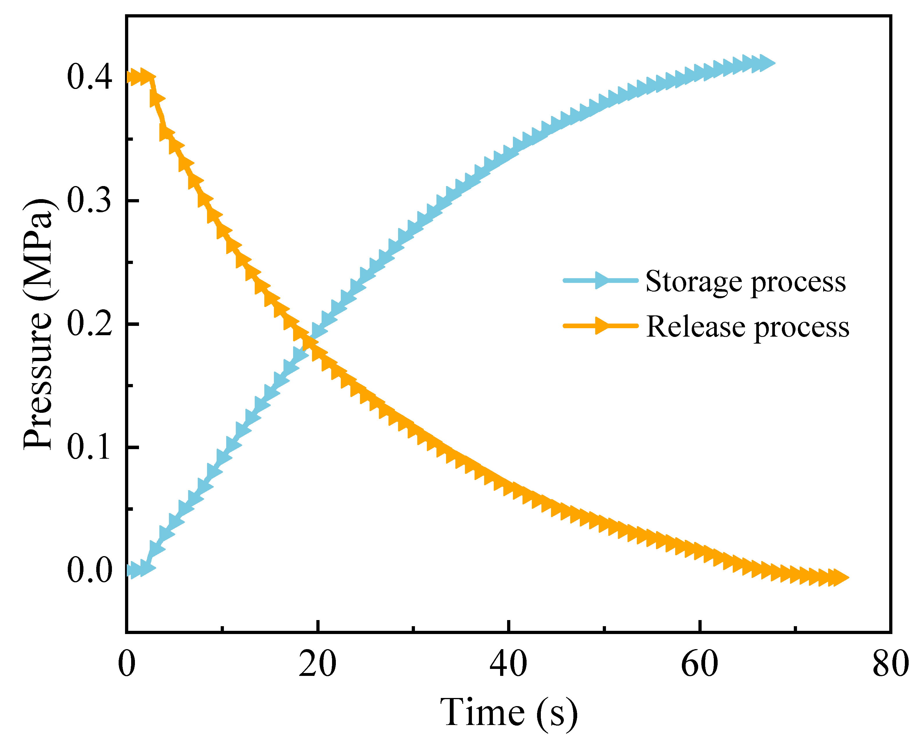
Figure 4 shows the gas pressure variation curve in the storage and release process of the gas storage tank with a volume of 30 L, an inlet pressure of 0.4 MPa, an inlet duration of 50 ms, an expansion duration of 50 ms and an exhaust expansion time of 30 ms. It can be seen that the time required for gas storage is less than the time required for gas release. During the process of gas storage and release, the changes in gas pressure show a trend of first fast and then slow.
Figure 5 shows the speed variation curves of the expander piston during the storage and release processes when the volume of the air storage tank is 30 L, the inlet pressure is 0.4 MPa, the inlet duration is 50 ms, the expansion duration is 50 ms and the exhaust expansion time is 30 ms. The velocity curve of the piston shows that the peak velocities of the piston in both positive and negative directions are different, further confirming that the movement of the piston has a certain degree of asymmetry. In addition, the peak velocity of the piston during the gas release process is slightly higher than that during the gas storage process. This is because during the gas storage process, the exhaust channel of the expander cylinder is connected to the gas storage tank, and the gradually increasing gas pressure in the gas storage tank creates a certain resistance to the piston’s movement, thereby affecting the piston’s movement speed. During the gas release process of the gas storage tank, the unused gas in the expander cylinder is directly discharged into the external environment, and the resistance in the exhaust chamber is relatively small, which has little impact on the piston movement.
Figure 6 shows the displacement variation curves of the expander piston during storage and release processes when the volume of the air storage tank is 50 L, the inlet pressure is 0.5 MPa, the inlet duration is 50 ms, the expansion duration is 50 ms and the exhaust expansion time is 30 ms. The initial position of the piston is on the left side of the expander cylinder before the movement starts. In order to make the reciprocating movement of the piston closer to the midpoint of the cylinder, the piston is pushed to the center-right position before reciprocating movement. From Figure 6, it can be seen that the piston is pushed from its initial position to its maximum displacement, and then undergoes a periodic reciprocating motion. During the gas storage process, due to the gradual increase in gas pressure inside the gas storage tank, the difference in gas pressure between the left and right sides decreases as the piston moves, and the movement amplitude of the piston also decreases. Until the gas pressure inside the gas storage tank is equal to the inlet pressure, the piston stops moving. During the gas release process, the actual stroke of the piston movement is greater than that of the gas storage process. When the gas in the storage tank is completely released, the piston stops moving.
In the process of gas recycling, the selection of the volume of the gas storage tank, the time required for the gas storage tank to reach a certain pressure and the pressure in the gas storage tank to be fully released, the peak speed of the piston movement and the actual stroke are all important performance parameters for realizing the cycle energy storage. Among them, the storage and release time can provide a reference for the setting of time parameters in each stage of the cycle process. The peak speed and actual stroke of the piston can provide a reference for the selection of expander cylinders. Therefore, this section discusses the effects of different operating conditions on storage and release time, piston peak speed and actual stroke.

3.1. Analysis of the Influence of Gas Tank Volume on the FPE-LG Gas Recycling Process

Figure 7 shows the curve of the time required for gas storage and release, the peak speed of the piston and the piston stroke as a function of the volume of the gas storage tank when the inlet pressure is 0.5 MPa and the inlet duration, expansion duration and exhaust duration are 50 ms, 50 ms and 30 ms, respectively. Figure 7a,b correspond to the gas storage process and gas release process, respectively. As shown in Figure 7, during the process of gas storage and release, as the volume of the gas storage tank increases, the time required for gas storage to 0.5 MPa and gas release from 0.5 MPa to the end of the release process gradually increases. This is because the volume of the gas storage tank increases, requiring more compressed gas to reach the same pressure and consuming a longer time. The peak speed and actual stroke of the piston also increase with the increase of the volume of the gas storage tank. This is because the exhaust channel of the expander cylinder is connected to the gas storage tank. As the volume of the gas storage tank increases, the gas pressure in the exhaust chamber of the expander cylinder increases slower, and the resistance to piston movement is smaller, resulting in a larger peak speed and stroke that the piston can reach.

3.2. Analysis of Influence of Inlet Pressure on FPE-LG Gas Recycling Process

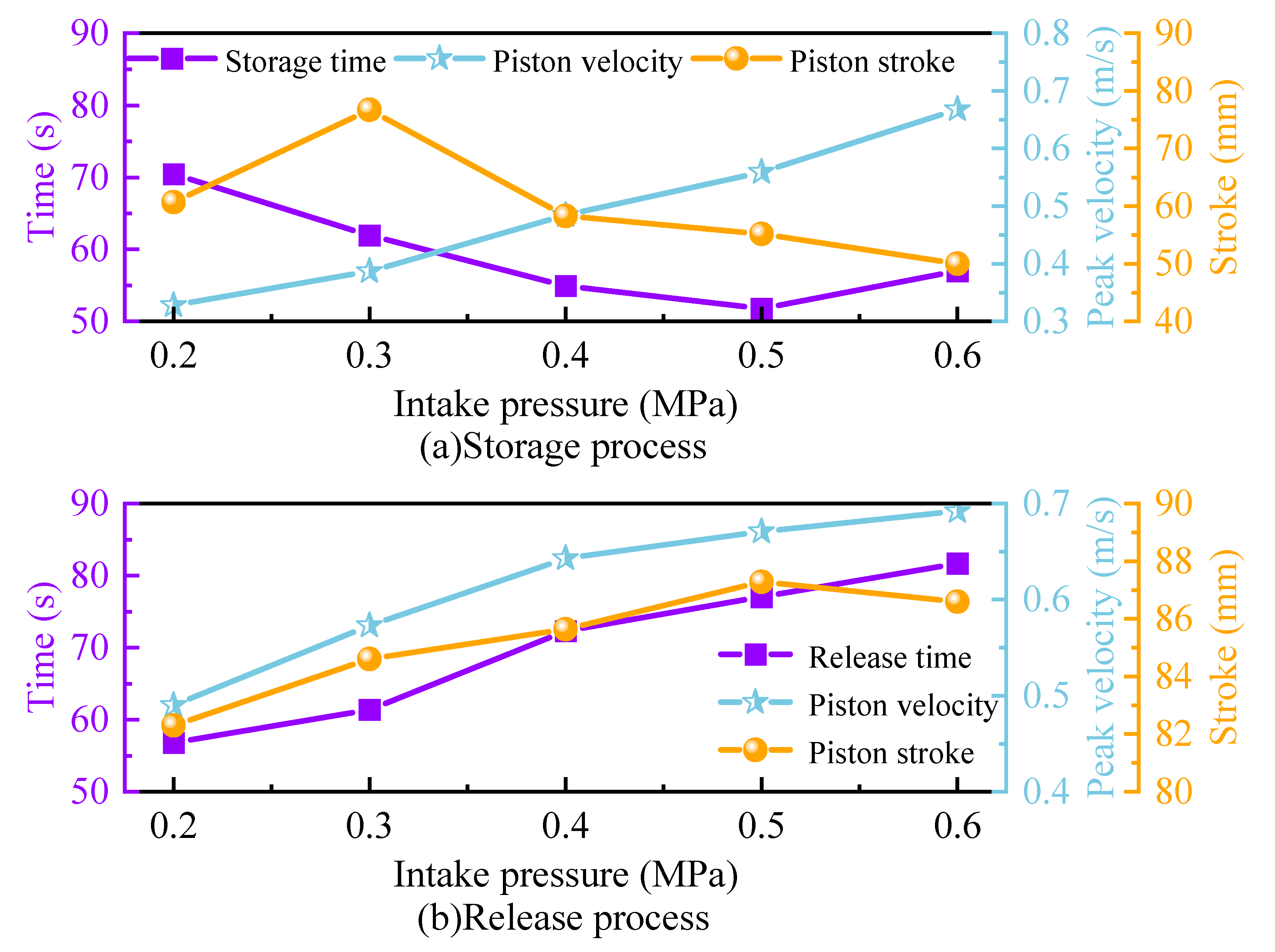
Figure 8 shows the curve of the time required for gas storage and release, the peak speed of the piston and the piston stroke as a function of the inlet pressure when the volume of the air tank is 30 L, and the inlet duration, expansion duration and exhaust duration are 50 ms, 50 ms and 30 ms respectively. Figure 8a,b correspond to the gas storage process and gas release process, respectively. As shown in Figure 8, as the intake pressure increases, the time required for gas storage to the corresponding pressure shows a trend of first decreasing and then increasing, with a storage time between 50 and 80 s. This is because as the intake pressure increases, when the piston stops moving, the pressure of the gas stored in the storage tank also increases accordingly. Therefore, the time required for the gas storage stage is not only related to the intake pressure. Therefore, in order to determine the impact of intake pressure on gas storage speed, it is necessary to control the pressure of the stored gas in the gas storage tank to be the same. In addition, during the gas release process, as the inlet pressure increases, the time required for complete gas release increases. This indicates that although increasing the inlet pressure will accelerate gas release, the release time did not decrease due to the high pressure in the gas storage tank itself. To determine the effect of intake pressure on the gas release rate, the gas pressure inside the gas storage tank is the same when controlling gas release. As the intake pressure increases, the peak velocity of the piston increases during gas storage and release processes. During the gas storage process, the piston stroke first increases, then decreases, and tends to stabilize with the increase of inlet pressure. During the gas release process, the change in inlet pressure has a small impact on the piston stroke, and the change in piston stroke is relatively large.
Figure 9 shows the time curve required to store the gas pressure in the gas storage tank to 0.2 MPa and fully release the gas from 0.2 MPa under different inlet pressures. As the intake pressure increases, the time required for gas storage to 0.2 MPa becomes shorter and shorter. The change in intake pressure has little effect on the time for complete gas release.

3.3. Analysis of the Influence of Intake Duration on the FPE-LG Gas Recycling Process

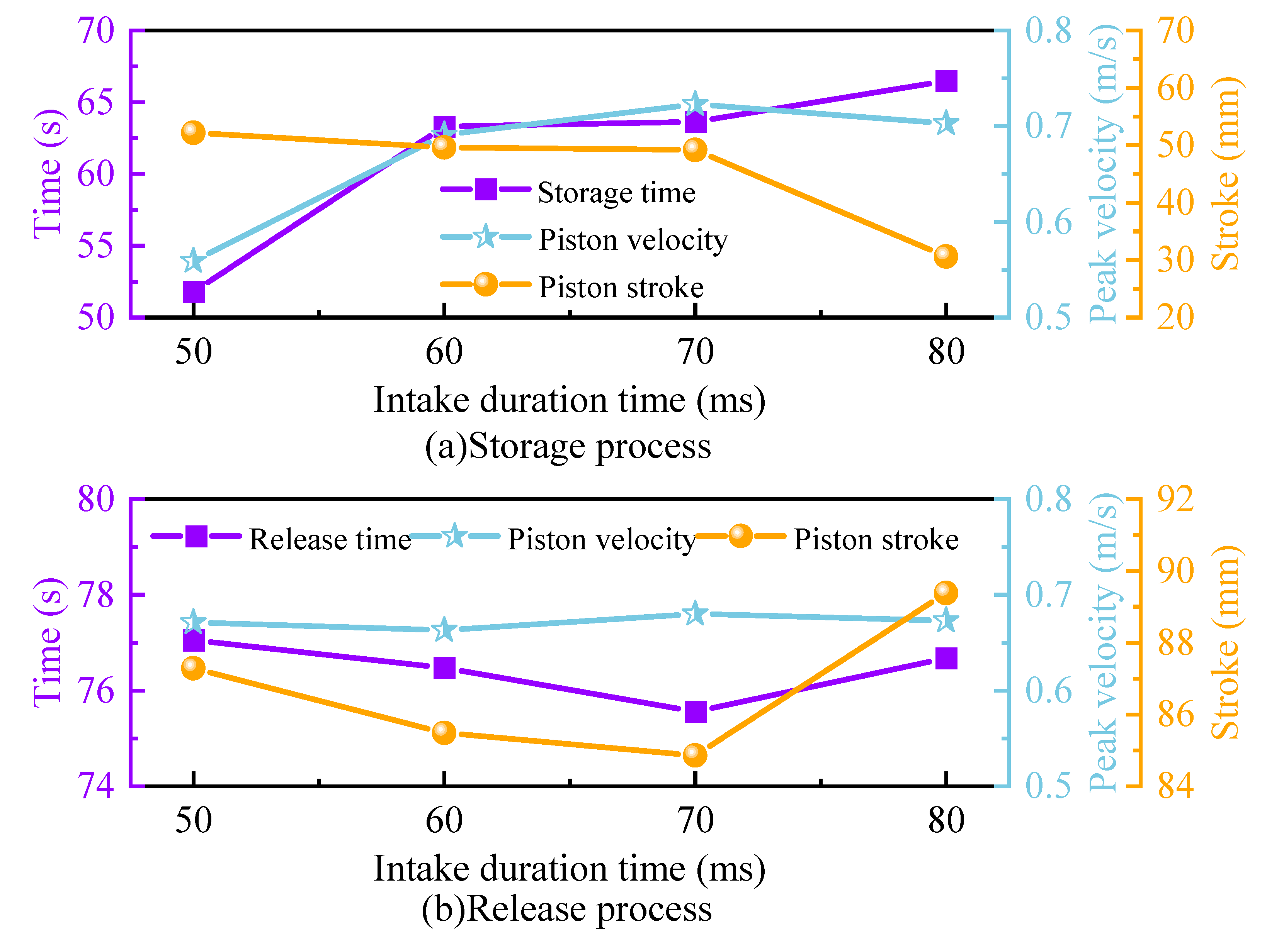
Figure 10 shows the curve of the time required for gas storage and release, the peak velocity of the piston, and the piston stroke as a function of the intake duration, when the volume of the gas storage tank is 30 L, the intake pressure is 0.5 MPa and the expansion duration and the exhaust duration are 50 ms and 30 ms, respectively. Figure 10a,b correspond to the gas storage and release processes, respectively. As shown in the figure, during the gas storage process, with the increase of intake duration, the time required for the gas to be stored in the gas storage tank to 0.5 MPa gradually increases. This is because under the same intake pressure, although the amount of gas entering the cylinder of the expander increases with the increase of intake duration, the same amount of gas entering the gas storage tank through the exhaust channel cannot improve the gas storage speed due to the same exhaust time. At the same time, as the duration of intake increases, an additional cycle time is added, thereby increasing the time required for the gas storage process and reducing the speed of gas storage. During gas storage, as the duration of intake increases, the peak velocity of the piston first increases and then stabilizes. The displacement of the piston shows a decreasing trend with the increase of intake duration. This is because as the intake duration increases, the duration of the intake phase of the piston is longer, and the piston speed increases. The gas in the exhaust chamber is compressed to a higher pressure, which hinders the piston’s movement. The maximum stroke that the piston can move is also correspondingly reduced. During the release process, the change in intake duration has a small impact on the time required for complete gas release, which is around 76 s. The peak velocity of the piston increases slightly with the increase in intake duration, and the change in piston stroke is also small, within 5 mm.

3.4. Impact Analysis of Expansion Duration on FPE-LG Gas Recycling Process

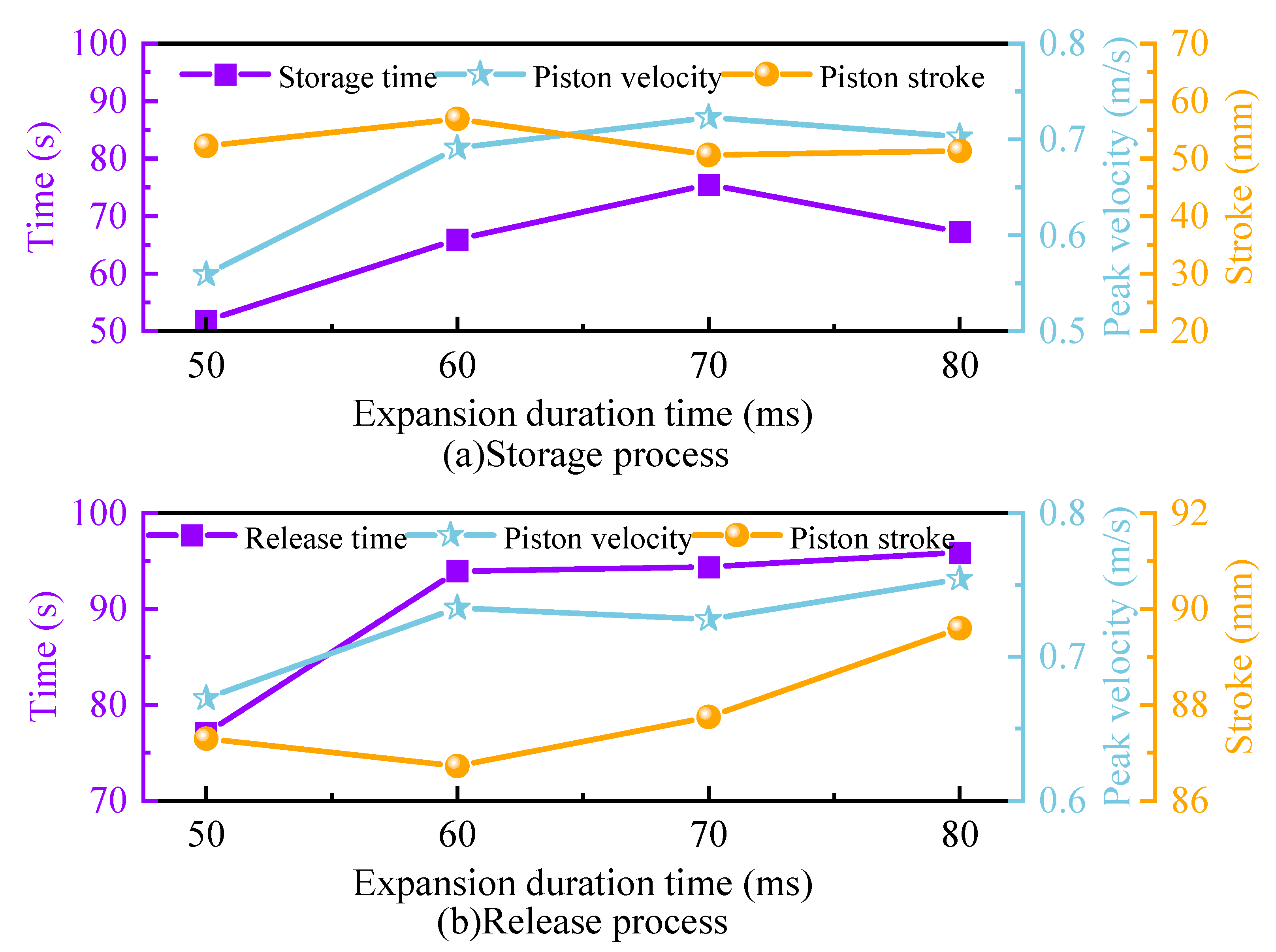
Figure 11 shows the curve of the time required for gas storage and release, the peak velocity of the piston and the piston stroke as a function of the intake duration, when the volume of the gas storage tank is 30 L, the intake pressure is 0.5 MPa and the intake and exhaust durations are 50 ms and 30 ms, respectively. Figure 11a,b correspond to the gas storage and release processes, respectively. As shown in the figure, during the gas storage process, as the expansion duration increases, the time required for storing gas in the gas storage tank to 0.5 MPa shows a trend of first increasing and then decreasing. This is because the expansion duration increases, and the gas entering the expander cylinder expands more fully. The gas pressure in the inlet chamber is lower compared to the short expansion duration. When the piston moves in the opposite direction, the intake chamber acts as the exhaust chamber and enters the exhaust stage. The pressure of the gas inside the chamber entering the gas storage tank is lower, and it takes longer to reach a certain pressure in the gas storage tank. When the expansion duration further increases, due to the long expansion duration, the piston undergoes reverse movement when the speed decreases to 0 m/s during the expansion phase, causing the gas in the intake chamber to be compressed and the pressure to increase. When the intake chamber serves as the exhaust chamber and enters the exhaust phase, the pressure of the gas entering the storage tank increases and the required storage time decreases. During the gas storage process, as the expansion duration increases, the peak velocity of the piston first increases and then stabilizes, and the piston stroke is less affected by the expansion duration. During the gas release process, as the expansion duration increases, the time required for complete gas release becomes longer because the cycle period becomes longer and the intake duration remains unchanged. The peak velocity and stroke of the piston both increase with the increase of expansion duration, but the increase is relatively small.

3.5. Analysis of Influence of Exhaust Duration on FPE-LG Gas Recycling Process

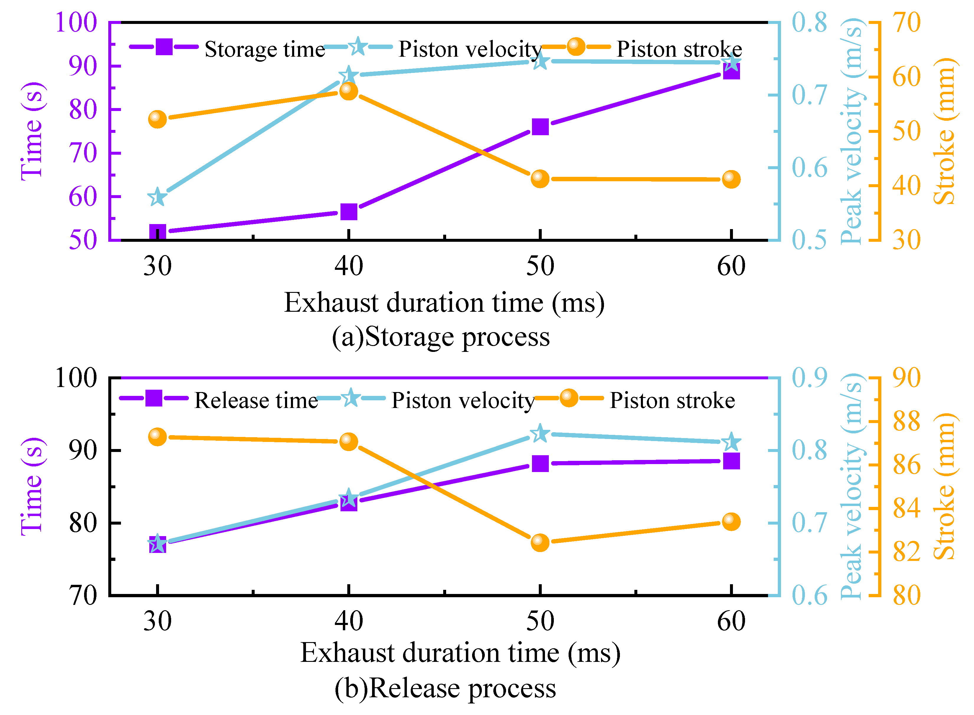
Figure 12 shows the curve chart of the time required for gas storage and release, the peak speed of the piston and the piston stroke changing with the exhaust duration when the volume of the air tank is 30 L, the inlet pressure is 0.5 MPa and the inlet duration and the expansion duration are both 50 ms. Figure 12a,b correspond to the gas storage process and the gas release process, respectively. As shown in the figure, during the gas storage process, as the exhaust duration increases, the time required for the gas to be stored in the gas storage tank to 0.5 MPa becomes longer. The peak velocity of the piston first increases and then tends to be flat, and the piston stroke first increases and then decreases. During the gas release process, the time required for complete gas release in the gas storage tank increases, and the peak velocity of the piston first increases and then slightly decreases. The piston stroke has no obvious change pattern and the change amplitude is small.

3.6. Impact Analysis of Electric Energy Storage during FPE-LG Gas Recycling

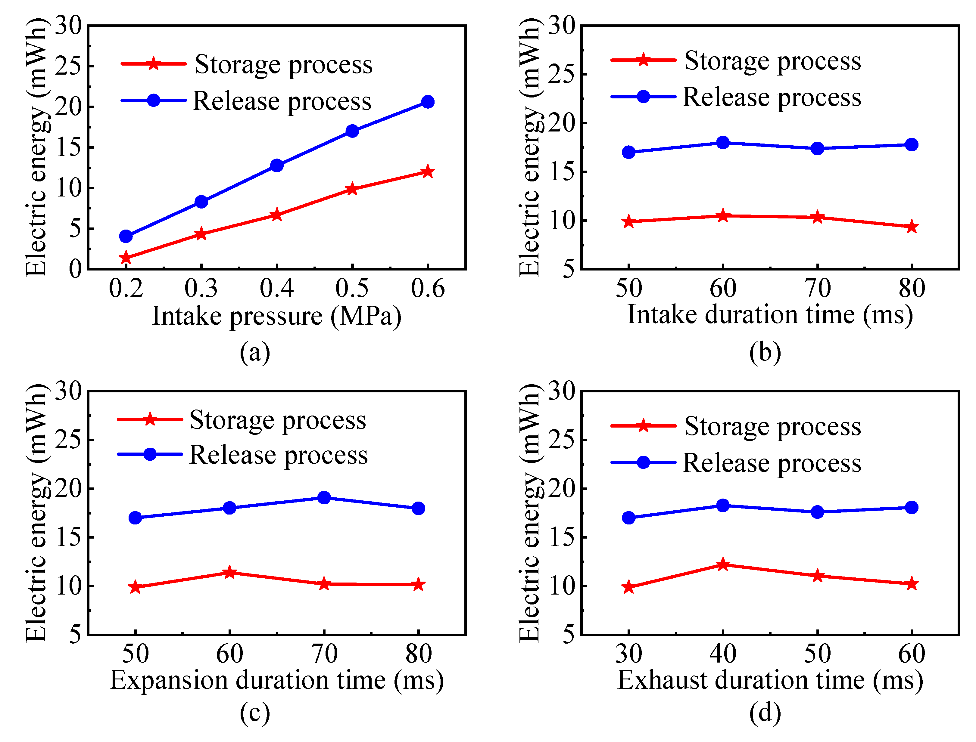
Figure 13 shows the impact curve of different operating conditions on the energy storage of lithium batteries during the cycling process with an air storage tank capacity of 50 L. It can be seen that during the gas storage process, the piston movement is affected by the pressure inside the gas storage tank, and under the same working conditions, the electrical energy stored in lithium batteries is lower than that during the gas release process. As the intake pressure (Figure 13a) increases, the amount of electrical energy stored in lithium batteries also increases. Intake duration (Figure 13b), expansion duration (Figure 13c) and exhaust duration (Figure 13d) have little influence on electric energy storage. During a cycle, the lithium battery during the gas storage phase can store approximately 10 mW·h of electrical energy, while the lithium battery during the gas release phase can store approximately 20 mW·h of electrical energy.

4. Summary and Conclusions

In order to recycle more automobile exhaust gas for use, this paper uses lithium batteries to store the electric energy generated by FPE-LG, and uses gas storage tanks to store the gas discharged from the exhaust valve of the expander cylinder, which verifies the feasibility of gas recycling, and analyzes the motion characteristics and output performance of the system during the process of gas storage and gas release in a cycle. The main conclusions are as follows:
  • The time required for gas storage is lower than the time required for gas release. By increasing the volume of the gas storage tank, the time required for gas storage and release becomes longer. Inlet pressure, inlet duration, expansion duration and exhaust duration all have different effects on the process of gas storage and release. When the volume of the gas storage tank is 50 L and the inlet pressure is 0.5 MPa, gas storage and gas release require 126.962 s and 131.242 s, respectively.
  • The actual stroke of the piston during gas storage is smaller than that during gas release. The volume of the gas storage tank and different operating conditions have a significant impact on the actual stroke of the piston during the gas storage process, while the impact on the gas release process is relatively small, the maximum actual stroke of the piston can reach 89.592 mm.
  • The peak velocity of the piston during gas storage is lower than that during gas release. The volume and inlet pressure of the gas storage tank have a significant impact on the peak velocity of the piston during storage, but have a smaller impact on the piston velocity during gas release. Increasing the volume and inlet pressure of the gas storage tank increases the peak velocity of the piston accordingly. The intake duration time, expansion duration time and exhaust duration time have little influence on the piston peak velocity.
  • The energy storage of lithium batteries increases with the increase of intake pressure, and the energy stored in lithium batteries during gas release is higher than that during gas storage. The intake duration, expansion duration and exhaust duration have little effect on the storage of lithium battery energy during the cycle.
In summary, the feasibility of gas cycle of an FPE-LG system is verified in this paper. However, the gas cycle will have a certain impact on the overall efficiency of the system, and the system efficiency can be further studied in the future.

Author Contributions

Conceptualization, B.P. and K.Z.; methodology, B.P., L.T. and K.Z.; software, B.P., L.T. and K.Z.; validation, B.P. and L.T.; formal analysis, B.P. and L.T.; investigation, B.P. and L.T.; validation, B.P. and L.T.; writing—original draft. B.P., L.T. and K.Z.; supervision, Y.X.; project administration, B.P., L.T. and K.Z.; funding acquisition, L.T. All authors have read and agreed to the published version of the manuscript.

Funding

This work was sponsored by the Beijing Natural Science Foundation (Grant No. 3222024).

Institutional Review Board Statement

Not applicable.

Informed Consent Statement

Informed consent was obtained from all subjects involved in the study.

Data Availability Statement

Data are available upon request.

Acknowledgments

The authors thank the support by the Beijing Natural Science Foundation (Grant No. 3222024).

Conflicts of Interest

The authors declare no conflict of interest.

Abbreviations

Nomenclature
pinIntake pressure (bar)
tinIntake duration time (ms)
texpExpansion duration time (ms)
texhExhaust duration time (ms)
Acronyms
ORCOrganic Rankine cycle
FPE-LGFree-piston expander–linear generator
LGLinear generator
OTDCOperation top dead center
OBDCOperation bottom dead center

References

  1. Feng, Y.; Hung, T.; Greg, K.; Zhang, Y.; Li, B.; Yang, J. Thermoeconomic comparison between pure and mixture working fluids of organic Rankine cycles (ORCs) for low temperature waste heat recovery. Energy Convers. Manag. 2015, 106, 859–872. [Google Scholar] [CrossRef]
  2. Wang, B.; Yu, X.; Xu, H.; Wu, Q.; Wang, L.; Huang, R.; Li, Z.; Zhou, Q. Scenario analysis, management, and optimization of a new Vehicle-to-Micro-Grid (V2μG) network based on off-grid renewable building energy systems. Appl. Energy 2022, 325, 119873. [Google Scholar] [CrossRef]
  3. Guo, T.; Wang, H.X.; Zhang, S.J. Fluids and parameters optimization for a novel cogeneration system driven by low-temperature geothermal sources. Energy 2011, 36, 2639–2649. [Google Scholar] [CrossRef]
  4. Catapano, F.; Frazzica, A.; Freni, A.; Manzan, M.; Micheli, D.; Palomba, V.; Sementa, P.; Vaglieco, B. Development and experimental testing of an integrated prototype based on Stirling, ORC and a latent thermal energy storage system for waste heat recovery in naval application. Appl. Energy 2022, 311, 118673. [Google Scholar] [CrossRef]
  5. Ramirez, M.; Epelde, M.; de Arteche, M.G.; Panizza, A.; Hammerschmid, A.; Baresi, M.; Monti, N. Performance evaluation of an ORC unit integrated to a waste heat recovery system in a steel mill. Energy Procedia 2017, 129, 535–542. [Google Scholar] [CrossRef]
  6. Lion, S.; Vlaskos, I.; Rouaud, C.; Taccani, R. Overview of the Activities on Heavy Duty Diesel Engines Waste Heat Recovery with Organic Rankine Cycles (ORC) in the Frame of the ECCO-MATE EU FP7 Project. Energy Procedia 2017, 129, 786–793. [Google Scholar] [CrossRef]
  7. Champagne, C.; Weiss, L. Performance analysis of a miniature free piston expander for waste heat energy harvesting. Energy Convers. Manag. 2013, 76, 883–892. [Google Scholar] [CrossRef]
  8. Preetham, B.; Weiss, L. Investigations of a new free piston expander engine cycle. Energy 2016, 106, 535–545. [Google Scholar] [CrossRef]
  9. Bouvier, J.L.; Lemort, V.; Michaux, G.; Salagnac, P.; Kientz, T. Experimental study of an oil-free steam piston expander for micro-combined heat and power systems. Appl. Energy 2016, 169, 788–798. [Google Scholar] [CrossRef]
  10. Burugupally, S.P.; Weiss, L. Design and performance of a miniature free piston expander. Energy 2019, 170, 611–618. [Google Scholar] [CrossRef]
  11. Wang, Y.; Chen, L.; Jia, B.; Roskilly, A.P. Experimental study of the operation characteristics of an air-driven free-piston linear expander. Appl. Energy 2017, 19, 93–99. [Google Scholar] [CrossRef]
  12. Wu, Z.; Zhang, H.; Liu, Z.; Hou, X.; Li, J.; Yang, F.; Zhang, J. Experimental study on the performance of single-piston free-piston expander—Linear generator. Energy 2021, 221, 119724. [Google Scholar] [CrossRef]
  13. Wu, Z.; Zhang, H.; Liu, Z.; Tian, G.; Hou, X.; Yang, F. Force and energy analysis of single-piston free-piston expander—Linear generator. Energy 2022, 251, 123926. [Google Scholar] [CrossRef]
  14. Xu, Y.H.; Tong, L.; Zhang, H.G.; Hou, X.C.; Yang, F.B.; Yu, F.; Yang, Y.X.; Liu, R.; Tian, Y.M.; Zhao, T.L. Experimental and simulation study of a free piston expander–linear generator for small–scale organic Rankine cycle. Energy 2018, 161, 776–791. [Google Scholar] [CrossRef]
  15. Gusev, S.; Ziviani, D.; Vierendeels, J.; De Paepe, M. Variable volume ratio free-piston expander: Prototyping and experimental campaign. Int. J. Refrig. 2019, 98, 70–79. [Google Scholar] [CrossRef]
  16. Tian, Y.; Zhang, H.; Li, G.; Hou, X.; Yu, F.; Yang, F.; Yang, Y.; Liu, Y. Experimental study on free piston linear generator (FPLG) used for waste heat recovery of vehicle engine. Appl. Therm. Eng. 2017, 127, 184–193. [Google Scholar] [CrossRef]
  17. Tian, Y.; Zhang, H.; Li, J.; Hou, X.; Zhao, T.; Yang, F.; Xu, Y.; Wang, X. Development and validation of a single-piston free piston expander-linear generator for a small-scale organic Rankine cycle. Energy 2018, 161, 809–820. [Google Scholar] [CrossRef]
  18. Li, G.; Zhang, H.; Yang, F.; Song, S.; Chang, Y.; Yu, F.; Wangle, J.; Yao, B. Preliminary Development of a Free Piston Expander–Linear Generator for Small-Scale Organic Rankine Cycle (ORC) Waste Heat Recovery System. Energies 2016, 9, 300–318. [Google Scholar] [CrossRef]
  19. Xu, Y.H.; Tong, L.; Zhang, H.G.; Hou, X.C.; Yang, F.B.; Yu, F.; Li, J.X.; Li, J.; Zhao, T.L.; Zhang, M.R. Experimental investigation of a free piston expander-linear generator with different valve timings. Appl. Therm. Eng. 2018, 142, 555–565. [Google Scholar] [CrossRef]
  20. Xu, Y.; Xue, X.; Wang, Y.; Ai, M. Performance characteristics of compressed air-driven free-piston linear generator (FPLG) system–A simulation study. Appl. Therm. Eng. 2019, 160, 114013. [Google Scholar] [CrossRef]
  21. Gao, J.; Ma, C.; Tian, G.; Xing, S.; Jenner, P. Numerical investigations of an opposed rotary piston expander for the purpose of the applications to a small-scale Rankine cycle. Appl. Therm. Eng. 2021, 182, 116157. [Google Scholar] [CrossRef]
  22. Burugupally, S.P.; Weiss, L.; Depcik, C. The effect of working fluid properties on the performance of a miniature free piston expander for waste heat harvesting. Appl. Therm. Eng. 2019, 151, 431–438. [Google Scholar] [CrossRef]
  23. Aziz, A.R.A.; Ismael, M.A.; Mohammed, S.E.; Baharom, M.B.; Anwarudin, A.R.T. Effect of generator configuration on the free-piston motion and power generation of air-driven expander system. Alex. Eng. J. 2022, 61, 3093–3104. [Google Scholar] [CrossRef]
  24. Ismael, M.A.; Aziz, A.R.A.; Mohammed, S.E.; Ayandotun, W.B.; Baharom, M.B.; Sallehudin, M.S.; Syakirin, M.; Anwerudin, A.R.T.; Masri, M.M. Investigation on free-piston motion and power generation of a dual-piston air-driven expander linear generator. Energy Rep. 2021, 7, 2388–2397. [Google Scholar] [CrossRef]
  25. Guo, C.; Zuo, Z.; Jia, B.; Zhang, Z.; Feng, H.; Roskilly, A. Parametric analysis of a dual-piston type free-piston gasoline engine linear generator. Energy Procedia 2019, 158, 1431–1436. [Google Scholar] [CrossRef]
  26. Song, Y.; Feng, H.; Zuo, Z.; Wang, M.; Guo, C. Comparison Research on Different Injection Control Strategy of CI Free Piston Linear Generator in One-time Starting Process. Energy Procedia 2014, 61, 1597–1601. [Google Scholar] [CrossRef]
  27. Shi, X.; Hou, X.; Yang, F.; Zhang, H.; Shi, Z.; Zhao, T.; Guan, X.; Wu, Y.; Zhang, J. Analysis on operation characteristic and output performance of free piston ex-pander-linear generator based on displacement control strategy. Appl. Therm. Eng. 2021, 182, 116146. [Google Scholar] [CrossRef]
Figure 1. FPE-LG Test Bench.
Sustainability 15 13993 g001
Figure 2. Schematic diagram of FPE-LG test bench.
Sustainability 15 13993 g002
Figure 3. Working principle diagram of FPE-LG.
Sustainability 15 13993 g003
Figure 4. Gas pressure change curve of gas storage tank.
Sustainability 15 13993 g004
Figure 5. Piston Speed Change Curve.
Sustainability 15 13993 g005
Figure 6. Piston displacement variation curve.
Sustainability 15 13993 g006
Figure 7. Effect of different storage tank volumes on the circulation process.
Sustainability 15 13993 g007
Figure 8. Effect of different intake pressures on the cycling process.
Sustainability 15 13993 g008
Figure 9. Effect of intake pressure on the time required for the storage tank to store and release the same pressure.
Sustainability 15 13993 g009
Figure 10. Effect of different intake durations on the cycling process.
Sustainability 15 13993 g010
Figure 11. Effect of different expansion durations on the cyclic process.
Sustainability 15 13993 g011
Figure 12. Effect of Different Exhaust Duration on the Cycle Process.
Sustainability 15 13993 g012
Figure 13. Effect of different operating conditions on stored electrical energy during the cycle process.
Sustainability 15 13993 g013
Table 1. The main parameters of the FPE-LG [13].
ItemsMain Parameters
CylinderDiameter 63 mm, stroke: 100 mm
Temperature sensorRange: 0–150 °C, accuracy: 0.5% FS
Pressure sensorRange: 0–10 bar, accuracy: 0.5% FS
Driving motorRated voltage 48 V, maximum speed: 7590 rpm, rated current 3.17 A, rated torque: 0.187 N·m
Solenoid valveRange: 0–10 bar
Dynamic torque sensorRange: 0–0.5 N·m, accuracy: 0.5% FS
Magnetic Powder BrakeTorque: 0–0.5 N·m, power: 8.4 W
Tension controllerOutput: DC 0–274 V, maximum current: 3 A
Three-phase rectifierRectification range: 0–30 A
Magnetic grid displacement sensorImage resolution: 0.5 μm
Linear generatorContinuous thrust 144 N, peak thrust: 576 N; Pole pitch: 30 mm, Back EMF constant: 20.9 V/(m·s−1),
Continuous current 2.3 A, peak current: 9.2 A
Table 2. Status of solenoid valves at different stages.
Electromagnetic Valve StatusDuration
Intake processopened V1, V4; closed V2, V3tin
Expansion processclosed V1, V2, V3, V4texp
Exhaust processopened V4; closed V1, V2, V3texh
Intake processopened V2, V3; closed V1, V4tin
Expansion processclosed V1, V2; V3, V4texp
Exhaust processopened V3; closed V1, V2, V4texh
Disclaimer/Publisher’s Note: The statements, opinions and data contained in all publications are solely those of the individual author(s) and contributor(s) and not of MDPI and/or the editor(s). MDPI and/or the editor(s) disclaim responsibility for any injury to people or property resulting from any ideas, methods, instructions or products referred to in the content.