Article

Identifying Members of Common Structures Utilizing Three-Dimensional Detecting Information for 3D Point Cloud Model Application

Department of Architectural Engineering, Kyonggi University, Yeongtong-Gu, Suwon 16227, Republic of Korea
*
Author to whom correspondence should be addressed.
Sustainability 2023, 15(19), 14073; https://doi.org/10.3390/su151914073
Submission received: 26 July 2023 / Revised: 21 September 2023 / Accepted: 21 September 2023 / Published: 22 September 2023

Abstract

:
This study focuses on improving progress monitoring in construction projects through the integration of 3D laser scanning technology and component-specific data identification. The conventional method of measuring progress using cost-based rates and on-site factors often leads to discrepancies between actual progress and reported rates. Additionally, data collection challenges in real construction sites further hinder accurate progress assessment. To address these issues, the study utilizes 3D laser scanning to gather real-time construction progress data and introduces a method to identify specific components by comparing 3D models with positional information. The method used in this study shows how to obtain powerful location information from BIM. This prevents direct duplicate operations from proceeding between models during execution. The comparison enables accurate identification, and an algorithm extracts additional details for construction status verification. The outcomes offer a promising solution for acquiring precise and reliable progress data, enabling stakeholders to make well-informed decisions. By implementing this approach, construction projects can achieve enhanced management and overall success.

1. Introduction

Among the various factors crucial for the successful execution of a construction project, progress management plays a vital role in providing information for identifying project progress and current status and and predicting potential issues [1]. Accurately measuring the progress rate is a prerequisite for precise and efficient progress management. Specifically, the progress rate serves as a key indicator for effective performance measurement in cost and schedule management [2]. Various methods are typically employed to measure the progress rate in construction work, including estimated progress measurement, actual workload measurement, and achieved progress recognition [3].
In construction project progress management, the progress rate is calculated by assigning weights based on the level of achievement for each unit task, comparing actual costs and schedules with the plan [4]. To accurately calculate the progress rate, it is ideal to quantify the execution based on the progress process rather than considering only the schedule or cost [5]. Consequently, numerous studies have been conducted to collect and evaluate objective and reliable progress rate data. However, the quantity and quality of the collected data are often limited due to challenges such as the burden of indirect expenses associated with collecting and analyzing reliable data on actual construction sites [6].
Recently, smart construction technologies have been extensively studied as management methods for achieving accurate and efficient construction projects in the construction field [7,8,9,10]. Among these technologies, 3D laser scanning has gained attention for its ability to acquire data that closely resembles reality [11]. A 3D point cloud model obtained through 3D laser scanning offers an accurate and efficient means to compare and verify design and actual construction conditions using 2D or 3D drawings. Consequently, this modeling technique is particularly applicable to complex sites that require precise management, such as atypical structures [12].
In this study, we focus on applying 3D laser scanning technology, along with smart construction technologies, to the progress management of construction projects. We utilize the C++ programming language to extract information, such as member names, types, and locations, from Building Information Modeling (BIM) with various input data. We propose a method for verifying the presence or absence of a member identified from a 3D point cloud model using the obtained information. Previous studies have explored methods for member recognition using 3D point cloud models and BIM, such as machine learning-based recognition of members through the analysis of features like columns, beams, and slabs using C++ [13], verification of member progress rates through collision events identified by overlapping the 3D model and 3D point cloud model [3], and member recognition using surface-based metric measurement after creating an optimal path 3D model through the interactive closest point (ICP) algorithm [14]. However, these previous studies primarily focused on member recognition based on complex programming, which presents limitations for practical implementation by hands-on workers on actual construction sites. Therefore, in this study, we propose a method for identifying members in a point cloud model using a simpler programming language.
The scope of this study is limited to the identification of data for each member comprising a building from a 3D point cloud model composed of point cloud data (PCD) obtained through 3D laser scanning, among various 3D modeling methods. This limitation arises because the 3D point cloud model in PCD format excels at capturing real-world data, but directly identifying members from the model is challenging as there are no discernible physical characteristics distinguishing individual members. However, BIM, which is a 3D information model based on 2D drawings, includes physical characteristics that define the shape of members [15]. Hence, to utilize the 3D point cloud model, we employ BIM to acquire member information and identify them within the 3D scanning model.
This study aims to introduce a method for precisely identifying individual data points within a 3D point cloud model generated using 3D laser scanning technology, facilitating the accurate delineation of 3D phenomena. Through the utilization of location data obtained from 3D laser scanning, it is anticipated that a wealth of information, including member types, characteristics, and locations, can be extracted from the point cloud model, surpassing the capabilities of a 3D model derived from design drawings. These insights far surpass the capabilities inherent in a 3D model fashioned solely from design drawings. It is our fervent belief that the approach outlined in this study has the potential to usher in a new era of heightened precision and objectivity in data collection, thereby reshaping the landscape of construction progress management with an eye toward sustainability.

2. Literature Review

2.1. Estabilishment of BIM

In the field of architecture, engineering, and construction (AEC), BIM is used as a tool for carrying out projects throughout their lifecycle, from planning, design, and construction to maintenance [16]. Converging with various technologies, BIM has significantly impacted project management [17]. Moreover, regulations and guidelines for mandatory BIM have been announced by domestic and foreign governments and public institutions [18]. The acceleration of technology introduction, such as mandatory BIM, has increased the importance of understanding and utilizing BIM.
BIM has the advantage that users can rapidly use various types of information, regardless of space and time, to facilitate information exchange [19]. BIM is defined as an object-centered expression method in a virtual space for reliable decision-making in the overall construction field [20]. The objects used for BIM production can be classified into three types, such as BSI [21], as shown in Table 1, and they have specific geometric characteristics, such as length, shape, and specification, and semantic characteristics, such as structure, materials, schedule, and cost [15]. Therefore, BIM is a technology used to manufacture targets using objects with various pieces of information and perform various analyses using the characteristics of objects.
With the activation of BIM, libraries have emerged as a concept for establishing 3D models. A library is an organized set of BIM objects that holds phenomenon and property information regarding the members constituting a building in performing a construction project using BIM [22]. Moreover, a library is used by users or designers to increase design understanding, reduce uncertainty in construction through requirements related to the objects used in modeling, and increase the reliability of the completed 3D model [23]. The library differs depending on the data characteristics of each 3D model production software package. Table 2 shows the composition of the library for the three software packages.

2.2. Utilization of 3D Point Cloud Model

The 3D point cloud model is a PCD-shaped three-dimensional model obtained using 3D laser scanning technology. The 3D laser scanner uses a measurement technology called light detection and ranging (LiDAR) or laser detection and ranging (LaDAR) to receive information, such as the speed, time, direction, and distance of the laser reflected from the target, and expresses the external shape of the target as a set of points in 3D coordinates [24]. Various types of 3D laser scanners are used at home and abroad. However, the time-of-flight (ToF) and phase-shift methods are the main types selected and used.
The PCD constituting the 3D point cloud model comprises a set of points, including the 3D position (x, y, z), color (RGB), and intensity. Each point comprises laser points reflected from the target, making it possible to collect data most similar to real data. Although the shape of a target can be predicted based on the collected data, the ability to obtain information on the configuration, which is a physical characteristic, such as the direct distinction of members constituting the target, is limited [3].
The establishment of a 3D point cloud model for analysis must involve a process of automatically or manually matching the obtained PCD. Because the PCD obtained first contains information on only a part of the target, matching implies integrating data acquired at each location into a single-coordinate system through unique features and merging them by reducing the error rate to an approximate value of ‘0’ through error correction [25]. The feature-point-based matching method is the most typically used method. In this method, regular geometrical features, such as window frames, building corners, and TLS targets, are used as unique features for matching [26]. The matching method used in Cheng et al. [27] is presented in Table 3.
A 3D point cloud model based on 3D scanning technology was applied to obtain data most similar to the actual scenario, as used in various fields, particularly in construction [9]. Representative studies include inspection and analysis of atypical interference parts in the building construction stage [12], production of as-built drawings and reverse engineering for maintenance [28], calculation of the amount of earthwork in the civil engineering work stage and process management [29], and quality and process management in the construction stage [14]. In addition, research has been actively conducted in various fields (Table 4).

3. Previous Research

A 3D point cloud model comprising a PCD obtained through 3D laser scanning technology and a 3D model comprising a mesh and volume were used to conduct various studies for recognizing structural members.
Turkan et al. [14] suggested a method for automatically updating progress by recognizing a 3D point cloud model in a 4D model containing schedule information for progress tracking management. This study proposed a method where the user defines several parameters and uses the surface-based recognition metric to recognize the members of the 3D point cloud model. Moreover, the 3D model was applied. In particular, the recognized member and schedule information could be used to calculate the number of working days according to the number of days for which the scan data were collected. Kim [3] suggests a progress management method using a 4D model. The as-built data were created through customization, such as manual and automatic matching and noise removal of 3D point cloud models of buildings acquired using drones and ground scanners. The member was recognized by checking the collision event when the generated data and the 3D model overlapped. Based on the case application, progress can be managed by comparing parts or quantities causing differences in construction progress through recognized objects. In these previous studies, an ICP algorithm aligned the 3D point cloud model with the 3D model. This technique is a powerful method for understanding the overall information to identify members by directly applying the overall 3D point cloud model to compare with the 3D model. However, directly using the entire data information of the 3D point cloud model composed of the PCD requires high-end hardware for calculating and processing the data generated when checking overlapping parts. Moreover, there may be a limit to its direct implementation in environments such as construction sites where research results must be used.
Kim et al. [34] proposed an object identification method that uses the color information and intensity of the acquired 3D point cloud model. The proposed object identification method converts the acquired 3D point cloud model into a hue–saturation–intensity (HSI) color space and recognizes objects by applying an algorithm recognizing concrete color information through a color model implemented with a 3D point cloud model using a support vector machine that can implement a color model. The recognized object was imported into the 3D model to verify whether it worked on the member. Zhang et al. [35] proposed an object identification method using an algorithm based on the object shape. Samir and Moselhi [36] developed an algorithm that calculated the threshold for the shape of each member by verifying the tolerance of the acquired scan data. As an object identification method, an algorithm calculating the point interval setting and threshold values of the ground scanner equipment used to acquire the 3D scanning model was employed to verify members in the 3D point cloud model. Maalek et al. [13] presented a machine learning method for identifying objects. In particular, from the acquired 3D point cloud model, the object identification method was applied only to columns and slabs, components of the frame construction, and the floor and ceiling slabs were identified using the characteristics of horizontal objects (x, y). For the columns, the features (z) of a vertical object in the space bounded by the floor and ceiling surfaces are identified. By learning the characteristics of each component, each member could be extracted from the 3D point cloud model and compared with the 3D model. These previous studies are considered powerful methods for identifying each member constituting a building by identifying information regarding objects from 3D point cloud models and comparing the identified objects with the 3D model. However, compared with the method of overlapping and comparing 3D point cloud models and 3D models, such as BIM, the process of identifying objects comprises complex algorithms, indicating that their applications are limited for actual construction sites, as in previous studies.
These previous studies show that automation technology is attracting attention due to the decreased construction workforce. Moreover, the use of smart construction technology, especially in the field of construction management, contributes to automating the process and schedule management. However, the methods proposed in previous research comprise complex algorithms used to recognize the object; therefore, managers at the construction site would have limitations in understanding and utilizing them. Note that the size of the data used is substantial; thus, limitations in the hardware arise when applying them to environments such as construction sites. Kavaliauskas et al. [37] proposed a method for automatically detecting the objects of industry foundation class (IFC) and 3D point cloud models and compared them with the BIM model to check whether members were identified. For object identification, a PCD structure model was created based on the vertex extraction of IFC objects, and the generated and 3D point cloud models were aligned to verify whether the members were identified. This is a powerful method for simplifying the member identification method, with increased usability using BIM information exchange tools such as IFC. However, there are limitations, such as developing a new model used for analysis and errors in the coordinate system while aligning the 3D point cloud model and BIM. Therefore, a method for obtaining and using simple but reliable data relying on simple algorithms and tools mainly used in the construction field must be developed to use these advanced technologies at construction sites.

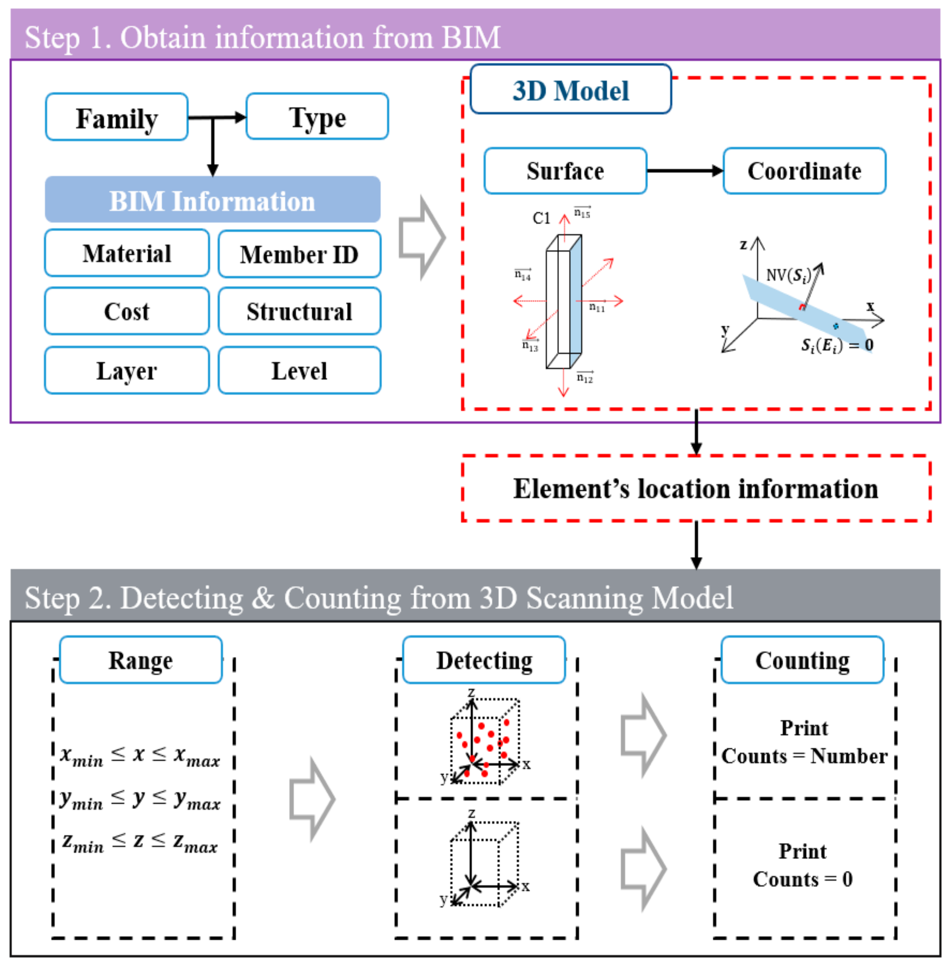
4. Identifying Member from 3D Point Cloud Model

As shown in Figure 1, we propose two new processes in this study. First, the information is extracted from BIM, and second, the data is identified from the 3D point cloud model using location information from the extracted information.

4.1. Acquiring Property Information and Location from 3D Model

To use a 3D model for various analyses, a process to match the coordinates shared between the models is required. This is because the external elements created during the process of comparing 3D models by matching shared coordinates can be blocked [13]. Maalek et al. [38] used a TLS target to match the coordinates between the 3D models for analysis, whereas Turkan et al. [14] used at least three points in a 3D CAD model to match the coordinates between the models. In addition, control points (CP) and benchmark points, used as reference points at construction sites, can be used to set a common coordinate system for the 3D models.
Figure 2 shows the process of obtaining the name of the member and the analysis coordinates to be identified in BIM after matching the coordinates shared between the 3D models.
Step 1. Select a group of members to acquire from BIM the acquisition information (Figure 3a).
Step 2. The surface of a member is identified using the surface function of the group of members. Three coordinate points are used on the identified surface to acquire the normal vector value ( N V S i = a i ,   b i ,   c i ) of the surface (Figure 3b).
Step 3. The acquired normal vector value is used to construct the plane equation ( S i E i ) and calculate an arbitrary coordinate point on the recognized member, as shown in Equation (1). The scope of the plane equation used to obtain an arbitrary coordinate point is limited to the recognized surface of the member to be identified. Moreover,  a i b i , and  c i  are the obtained normal vector values,  d i  is the distance between the plane and origin, and  x y , and  z  are the selected arbitrary coordinate values.
S i E i = a i x + b i y + c i z + d i
Step 4. If an arbitrary coordinate point is on the plane, as shown in Equation (2), the corresponding coordinate value is saved in the buffer (Figure 3c).
S i E i = 0
The value that satisfies Step 4 allows for obtaining an arbitrary coordinate point and the member name of the member to be identified. Moreover, the obtained information enables identifying the member to be checked in the 3D point cloud model composed of the PCD.

4.2. Identification of Data from 3D Point Cloud Model Based on Acquired Information

Figure 4 shows the data identification process for each member using the 3D point cloud model.
Step 1. Load an arbitrary coordinate point acquired in Figure 2.
Step 2. Set the recognition range, as shown in Equation (3), according to the characteristics of the member to be identified. Equation (4) expresses the recognition range. In particular,  d r  is the recognition range and P is an arbitrary coordinate point ( x y z ) obtained using Figure 2.
r a n g e m i n ,   m a x   =   P   ±   d r
x m i n x x m a x ,   y m i n y y m a x ,   z m i n z z m a x
Step 3. Output 0 if a point is not recognized within the set recognition range and measure the number of points if recognized.
Step 4. Output the name of the member, arbitrary coordinate points, and the number of points based on the number of points measured.

5. Discussion

In this study, a method is introduced for identifying data pertaining to each member from a 3D point cloud model obtained through 3D laser scanning technology. The proposed method holds significant implications for construction progress management within the realm of smart construction technologies. The limitations associated with directly utilizing 3D point cloud models, as highlighted in previous research reviews, as well as the complexities arising from intricate algorithms, have been successfully addressed. Instead, a simplified algorithm has been developed to effectively determine member data from the 3D point cloud model.
The method presented in this study can be implemented utilizing well-known tools such as Revit and ArchiCAD, widely employed within construction site environments. By incorporating the requisite information, this method facilitates efficient data identification, thereby enhancing overall construction progress management efficiency. It is worth noting, however, that the successful application of the proposed method necessitates the fulfillment of two prerequisites. Firstly, personnel possessing the necessary skills and expertise in 3D laser scanning technology are required. These individuals play a crucial role in acquiring precise and high-quality scanning data, which serves as the foundation for the subsequent identification process. Investing in training and education to cultivate a skilled workforce in this field will be pivotal for the future implementation of the method. Secondly, personnel proficient in utilizing BIM building tools such as Revit and ArchiCAD are indispensable. These tools facilitate the integration of identified data into the construction progress management system, streamlining the overall process. Ensuring that construction professionals are equipped with the requisite knowledge and training in BIM tools is vital for the successful adoption of the method. Despite these prerequisites, it is important to highlight the favorable environment fostered by the recent activation and legislation of smart construction technologies, including BIM and 3D laser scanning, in addressing these challenges. With the continued momentum and wider adoption of these technologies, we can anticipate increased availability of skilled personnel and improved support for training.
Looking ahead, future studies should prioritize the development of a comprehensive system that integrates smart construction technologies into construction progress management, capitalizing on the method proposed in this study. Such a system has substantial potential to contribute to the digitalization and optimization of various management aspects within the construction industry. Harnessing the power of smart construction technologies enables enhanced project efficiency, cost reduction, error minimization, and improved project outcomes.

6. Conclusions

In conclusion, progress management stands out as a critical factor among the myriad elements contributing to the success of construction projects. This paper has underscored the importance of comprehending project progress and delivering essential information in this regard. In the quest for precise progress management, numerous studies have been dedicated to accurately gauging progress rates.
Within the scope of this research, we harnessed the power of 3D laser scanning technology, enabling a profound understanding of phenomena in three-dimensional space through precise data measurement. The creation of a 3D point cloud model through 3D laser scanning opened doors to a novel method for identifying construction elements within this model. This, in turn, led to the development of a methodology for verifying the completion of construction components on-site, utilizing Building Information Modeling (BIM) in conjunction with the PCD.
Nevertheless, the practical implementation of our proposed method necessitates addressing specific prerequisites. First and foremost, securing experts proficient in 3D laser scanning technology is paramount, given the scarcity of skilled personnel capable of operating this technology, especially in specialized environments like construction sites. Additionally, fostering a comprehensive understanding of this technology among project stakeholders is essential, as the ultimate objective of this study is to apply these methods to real-world projects, mitigating various practical challenges through collaborative consultation.
Moreover, it is crucial to acknowledge other potential limitations, including the requirement for proficiency in programming languages and comprehension of design drawings. We anticipate future endeavors will focus on applying the findings of this study to actual construction projects, identifying and resolving issues that may arise during real-world applications. In this way, this study’s outcomes hold the potential to significantly enhance efficiency in construction project management by integrating smart construction technology into the process management domain.

Author Contributions

J.-Y.K. reviewed the existing literature, Conceptualization, Methodology, Investigation and Writing.; G.-H.K. conceived the whole this study and conducted a review of the research results. All authors have read and agreed to the published version of the manuscript.

Funding

This work was supported by the National Research Foundation of Korea (NRF) grant funded by the Korea government (MIST) (NO. 2022R1A4A5028239).

Institutional Review Board Statement

Not applicable.

Informed Consent Statement

Not applicable.

Data Availability Statement

The data presented in this study are available on request from the corresponding author. The data are not publicly available due to restrictions on right of privacy.

Conflicts of Interest

The authors declare no conflict of interest.

References

  1. Kang, S.H.; Jung, Y.S. Data acquisition technology (DAT) selection algorithm for automated progress measurement and management. Korea J. Constr. Eng. Manag. 2012, 13, 77–86. [Google Scholar] [CrossRef]
  2. Kang, S.H. Utilizing Data Acquisition Technology (DAT) for Automated Construction Progress Management. Master’s Thesis, Myungji University, Seoul, Republic of Korea, 2008. [Google Scholar]
  3. Kim, S.H. The Construction Project EV Tracking Process based on the 3D Point Cloud and 4D BIM. Ph.D. Thesis, Yeungnam University, Gyeongsan, Republic of Korea, 2019. [Google Scholar]
  4. Lee, K.H.; Park, C.J.; Choi, I.S. A study on the improvement of construction progress management for EVMS. Korea J. Constr. Eng. Manag. 2002, 2, 155–162. [Google Scholar]
  5. Park, J.S. A Study on the Schedule Process for Forecasting Progress Rate for Construction Project. Master’s Thesis, Gyeongsang National University, Jinju-si, Republic of Korea, 2011. [Google Scholar]
  6. Jung, Y.S.; Woo, S.K. Flexible work breakdown structure for integrated cost and schedule control. J. Constr. Eng. Manag. 2004, 130, 616–625. [Google Scholar] [CrossRef]
  7. Sepasgozar, S.M.E.; Hui, F.K.P.; Shirowzhan, S.; Foroozanfar, M.; Yang, L.; Aye, L. Lean practices using building information modeling (BIM) and digital twinning for sustainable construction. Sustainability 2021, 13, 161. [Google Scholar] [CrossRef]
  8. Ammad, S.; Wesam, S.A.; Saad, S.; Abdul, H.Q. Personal protective equipment (PPE) usage in construction projects: A systematic review and smart PLS approach. Ain Shams Eng. J. 2021, 12, 3495–3507. [Google Scholar] [CrossRef]
  9. Kim, J.Y.; Kim, G.H. Application of 3D laser scanning technology to the measurement of construction precision in building structural frame construction. J. Archit. Inst. Korea 2022, 38, 245–253. [Google Scholar] [CrossRef]
  10. Medina, A.L.; Herrera-Pérez, V.; Cantal, L.R.P.; Rojas, M.M. Internet of Things for Construction Project Management: A Systematic Literature Review. In IoT and Data Science in Engineering Management. CIO 2022. Lecture Notes on Data Engineering and Communications Technologies; García Márquez, F.P., Segovia Ramiterat, I., Bernalte Sánchez, P.J., Muñoz del Río, A., Eds.; Springer: Berlin/Heidelberg, Germany, 2023; Volume 160, pp. 286–291. [Google Scholar] [CrossRef]
  11. Arayici, Y. An approach for real world data modelling with the 3D terrestrial laser scanner for built environment. Autom. Constr. 2007, 16, 816–829. [Google Scholar] [CrossRef]
  12. Wang, J.; Yi, T.; Liang, X.; Ueda, T. Application of 3D laser scanning technology using laser radar system to error analysis in the curtain wall construction. Remote Sens. 2023, 15, 64. [Google Scholar] [CrossRef]
  13. Maalek, R.; Lichti, D.D.; Ruwanpura, J.Y. Automatic recognition of common structural elements from point clouds for automated progress monitoring and dimensional quality control in reinforced concrete construction. Remote Sens. 2019, 11, 1102. [Google Scholar] [CrossRef]
  14. Turkan, Y.; Bosche, F.; Hass, C.T.; Hass, R. Automated progress tracking using 4D schedule and 3D sensing technology. Autom. Constr. 2012, 22, 414–421. [Google Scholar] [CrossRef]
  15. Su, S.; Wang, Q.; Han, L.; Hong, J.; Liu, Z. BIM-DLCA: An integrated dynamic environmental impact assessment model for buildings. Build. Environ. 2020, 183, 107218. [Google Scholar] [CrossRef]
  16. Ho, S.P.; Liu, L.Y. Analytical model for analyzing construction claims and opportunistic bidding. J. Constr. Eng. Manag. 2004, 130, 94–104. [Google Scholar] [CrossRef]
  17. Koseoglu, O.; Keskin, B.; Ozorhon, B. Challenges and enablers in BIM-enabled digital transformation in mega projects: The Istanbul new airport project case study. Buildings 2019, 9, 115. [Google Scholar] [CrossRef]
  18. Autodesk. Autodesk BIM Report; 2021.10; Autodesk: San Francisco, CA, USA, 2021. [Google Scholar]
  19. Ministry of Infrastructure and Transport. BIM Basic Guidelines for the Construction Industry; 2020.12; Ministry of Infrastructure and Transport: Sejong-Si, Republic of Korea, 2020.
  20. ISO 29481-1:2010; Building Information Modelling—Information Delivery Manual—Part 1: Methodology and Format. ISO: Geneva, Switzerland, 2010.
  21. BS 8541-1:2012; Library Objects for Architecture, Engineering and Construction. Identification and Classification. BSI: London, UK, 2012.
  22. Shin, J.H.; Choi, J.S.; Kim, I.H.; Yoon, D.Y. A Study on Development of Integrated Management System for BIM Property Information. Korean J. Comput. Des. Eng. 2016, 21, 130–142. [Google Scholar] [CrossRef]
  23. Jung, B.C. Manufacturer BIM library construction example. KARSE 2010, 1, 87–94. [Google Scholar]
  24. Kwom, S.O. Application of Shape Information Acquisition Technology using Laser Scanning Technology and BIM Technology to the Construction Industry. Architecture 2009, 52, 31–38. [Google Scholar]
  25. Liu, P.; Chen, A.Y.; Huang, Y.-N.; Han, J.-Y.; Lai, J.-S.; Kang, S.-C.; Wu, T.-H.; Wen, M.C.; Tsai, M.-H. A review of rotorcraft Unmanned Aerial Vehicle (UAV) developments and applications in civil engineering. Smart Struct. Syst. 2014, 13, 1065–1094. [Google Scholar] [CrossRef]
  26. Weinmann, M. Point Cloud Registration. Reconstruction and Analysis of 3D Scenes; Springer: Berlin/Heidelberg, Germany, 2016; pp. 55–110. [Google Scholar] [CrossRef]
  27. Cheng, L.; Chen, S.; Liu, X.; Xu, H.; Wu, Y.; Li, M.; Chen, Y. Registration of laser scanning point clouds: A review. Sensors 2018, 18, 1641. [Google Scholar] [CrossRef]
  28. Bernat, M.; Janowski, A.; Rzepa, S.; Sobieraj, A.; Szulwic, J. Studies on the use of terrestrial laser scanning in the maintenance of buildings belonging to the cultural heritage. In Proceedings of the 14th Geoconference on Informatics, Geoinformatics and Remote Sensing, SGEM, ORG, Albena, Bulgaria, 17–26 June 2014; pp. 307–318. [Google Scholar]
  29. Park, J.W.; Kim, S. Productivity analysis for the 3D digitization of earthwork sites based on scanning conditions. Inter. J. Railw. 2018, 11, 1–9. [Google Scholar]
  30. Jang, A.; Ju, Y.K.; Park, M.J. Structural stability evaluation of existing buildings by reverse engineering with 3D laser scanner. Remote Sens. 2022, 14, 2325. [Google Scholar] [CrossRef]
  31. Moyano, J.; Ángel, J.-E.; Juan, E.N.-J.; Barrera, A.O.; Maria, F.A. Evaluation of records using terrestrial laser scanner in architectural heritage for information modeling in HBIM construction: The case study of the La Anunciación church (Seville). J. Build. Eng. 2022, 62, 105190. [Google Scholar] [CrossRef]
  32. Hosamo, H.H.; Hosamo, M.H. Digital twin technology for bridge maintenance using 3D laser Scanning: A review. Adv. Civ. Eng. 2022, 2022, 2194949. [Google Scholar] [CrossRef]
  33. Singh, K.S.; Banerjee, B.P.; Raval, S. A review of laser scanning for geological and geotechnical applications in underground mining. Int. J. Min. Sci. Technol. 2023, 33, 133–154. [Google Scholar] [CrossRef]
  34. Kim, C.M.; Son, H.J.; Kim, C.W. Automated construciton progress measurment using a 4D building information model and 3D data. Autom. Constr. 2013, 31, 75–83. [Google Scholar] [CrossRef]
  35. Zhang, C.; Arditi, D. Automated progress control using laser scanning technology. Autom. Constr. 2013, 36, 108–116. [Google Scholar] [CrossRef]
  36. Samir, E.O.; Osama, M. Integrating 3D laser scanning and photogrammetry for progress measurement of construction work. Autom. Constr. 2008, 18, 1–9. [Google Scholar] [CrossRef]
  37. Kavaliauskas, P.; Fernandez, J.B.; McGuinness, K.; Jurelionis, A. Automation of construction progress monitoring by integrating 3D point cloud data with an IFC-based BIM model. Buildings 2022, 12, 1754. [Google Scholar] [CrossRef]
  38. Maalek, R.; Lichti, D.D.; Walker, R.; Bhavnani, A.; Ruwanpura, J.Y. Extraction of pipes and flanges from point clouds for automated verification of prefabricated modules in oil and gas refinery projects. Autom. Constr. 2019, 103, 150–167. [Google Scholar] [CrossRef]
Figure 1. Flow chart to identify elements from the 3D point cloud model.
Sustainability 15 14073 g001
Figure 2. Step-by-step approach to obtain the information from BIM.
Sustainability 15 14073 g002
Figure 3. Obtaining a point over the objects surface. (a) Select object from BIM. (b) Recognition of surface from object. (c) Obtain a point satisfying the conditions.
Sustainability 15 14073 g003
Figure 4. Step-by-step approach for detecting and counting from the 3D point cloud model.
Sustainability 15 14073 g004
Table 1. BIM object.
TypeDefinitionUtilizationInformation
Sample objectProvide guide and property information for a created objectSchematic DesignShape
Identification
General objectProvide information for detailed expression and analysisDesign DevelopmentShape
Identification
Performance
Product objectProvide information for products to be installed in buildingConstruction Document
Construction Administration
Shape
Identification
Performance
Product
Table 2. Composition of a library in BIM software packages.
TypeData StructureLibraryExample
RevitModel elements
Annotation elements
View elements
Category
Family
Type
Column, Wall, Beam ···
C1, C2, C3, W1, W2, B1 ···
150 × 150, 200 × 200 ···
Archi CadObject elements
Layer elements
Object property
Layer combination
Layer
Layer extension
Column, Wall, Beam ···
Drafting, Plans, Site ···
Interior, Finish, Annotation
BentleyParts
Component
Compound
Object information
Object property
Column, Wall, Beam
Definition, Cost, Type
Table 3. Registration methods for PCD.
Recognize TypeFeature Type
Point-basedPoint feature/Point domain feature/Rotated image feature
Line-basedALS, MLS
Combination of building contours and road networks
Surface-basedLeast squares surface/Conjugate surface
Table 4. Previous research of 3D scanning technology applied to AEC.
SubjectAuthor(s)Research Title
ArchitectureBernat et al. [28]Research on reverse engineering method for building maintenance using 3D laser scanning
Jang et al. [30]Utilize 3D laser scanning to obtain inverse design data for existing buildings and conduct structural safety assessments
Moyano et al. [31]Presentation of data collection and recording methods for architectural heritage using 3D laser scanning
EngineeringPark and Kim [29]Research on calculating the amount of earthwork and the process control method in the civil engineering work stage
Hosamo and Hosamo [32]Research on digital twin technology for bridge maintenance management using 3D laser scanning
Singh et al. [33]Research on geotechnical analysis of underground mines using 3D laser scanning
ConstructionTurkan et al. [14]Research on 4D management method by automatic object recognition method from models by applying 3D laser scanning
Kim and Kim [9]Study quality confirmation methods of framework during building construction using 3D laser scanning technology
Wang et al. [12]Study error analysis based on atypical curtain wall construction data obtained using 3D laser scanning
Disclaimer/Publisher’s Note: The statements, opinions and data contained in all publications are solely those of the individual author(s) and contributor(s) and not of MDPI and/or the editor(s). MDPI and/or the editor(s) disclaim responsibility for any injury to people or property resulting from any ideas, methods, instructions or products referred to in the content.

