Article

Influence of Steel and Polypropylene Fibers on the Structural Behavior of Sustainable Reinforced Lightweight Concrete Beams Made from Crushed Clay Bricks

by
Esraa A. Elsherbiny
1,
Mohamed Mortagi
2,
Osama Youssf
2,*,
Mohamed Abd Elrahman
2 and
Mohamed E. El Madawy
2
1
Structural Engineering Department, Faculty of Engineering, Damietta University, Damietta 34519, Egypt
2
Structural Engineering Department, Faculty of Engineering, Mansoura University, Mansoura 35516, Egypt
*
Author to whom correspondence should be addressed.
Sustainability 2023, 15(19), 14570; https://doi.org/10.3390/su151914570
Submission received: 1 September 2023 / Revised: 4 October 2023 / Accepted: 6 October 2023 / Published: 8 October 2023
(This article belongs to the Section Sustainable Engineering and Science)

Abstract

:
Structural lightweight concrete is preferred over traditional concrete due to its ability to reduce the dead load, minimize the size of load-bearing structural members, and provide more economical solutions for foundation deteriorations. This research sheds light on sustainable lightweight concrete using waste crushed clay bricks (CCB) as a lightweight aggregate. To reduce micro-crack propagation of the developed concrete, two types of fiber were implemented and investigated. Steel fibers (SF) with amounts of 0.5% and 1.0% by volume of concrete, and polypropylene fibers (PPF) with amounts of 0.1% and 0.2% by volume of concrete, were employed. Five reinforced concrete beams were made and tested in order to precisely evaluate the structural behavior of the proposed lightweight CCB concrete. Additionally, ABAQUS software for nonlinear finite element analysis has been utilized to simulate the tested beams and compare the numerical model predictions with the experimental findings. The findings revealed that the addition of SF and PPF exhibited a notable influence on enhancing the mechanical characteristics of lightweight CCB concrete. Adding 0.2% PPF increased the ultimate load and deformation capacity at failure by approximately 16% and 24%, respectively. Furthermore, after 28 days, the addition of 0.5% and 1.0% SF enhanced the compressive strength by around 11.7% and 17.6%, respectively. Moreover, a significant level of consistency between the results obtained from the numerical model and the experimental findings was observed. In general, the use of SF and PPF in CCB concrete successfully produced high-quality lightweight concrete with interesting results for use in reinforced concrete beams.

1. Introduction

Normal concrete has numerous advantages such as strength, versatility, durability, soundproofing, less required maintenance, and energy efficiency. It has some drawbacks such as high density, natural resources consumption, and less sustainability. To overcome the concrete drawbacks, various types of lightweight concrete (LWC) have been developed and implemented in several constructions. LWC can be manufactured by using lightweight aggregates or by creating voids in concrete like foam concrete [1,2,3]. There are a variety of lightweight aggregates that can be used such as pumice, scoria, volcanic stones, rubber, and lightweight expanded clay aggregates (LECA), but all these materials are available in certain regions [4,5]. Artificial lightweight aggregates present a proper solution for producing LWC. However, their relatively high cost and their high energy consumption during manufacturing make them hard and unsustainable to use in concrete [6]. To tackle these challenges, some types of waste materials can be recycled and used as lightweight aggregates, such as crushed clay bricks (CCB).
Recycled aggregate concrete is of great interest due to its cost-effectiveness, sustainability, and eco-friendliness [7,8,9]. Crushed, sorted, and cleaned construction waste, masonry bricks, and demolished infrastructure are the sources of recycled aggregates for concrete [10,11,12]. CCB aggregates can be utilized as an alternative to natural fine and coarse aggregates to create environmentally friendly concrete, according to several research [13,14,15,16]. Dry densities below 1950 kg/ m 3 have been achieved by incorporating waste CCB as coarse and fine aggregates [17,18]. Researchers began to produce structural CCB concrete to reduce the dead load of residential and non-residential buildings in seismic areas. CCB concrete is promising in many structural applications where the thermal resistance, cost, and environmental aspects are essential. Moreover, it can minimize the size of the load-bearing of structural elements, resulting in more economical solutions for foundation problems [19,20,21]. The high-water absorption of waste CCB aggregate can lead to poor workability of the produced concrete, which is a major disadvantage [17,22]. Researchers have attempted to overcome this issue by using additional water or employing the aggregate in a saturated surface dry state [17,20,21,22,23,24,25].
Structural concrete is characterized by its low tensile strength and high compressive strength [26,27,28]. Adding a small amount of fibers to concrete can greatly enhance its tensile and flexural strengths [29] Additionally, a moderate increase in compressive strength can also be observed in fiber-reinforced concrete due to the high strain-hardening response of fibers under loading [30,31,32]. As mentioned by Aulia [33], using fibers can mitigate early plastic shrinkage cracking and enhance the ductility behavior and tensile capacity of high-strength concrete by bridging forces across cracks. Furthermore, Banthia and Gupta [34] demonstrated that polypropylene fiber (PPF) aids in controlling plastic shrinkage cracking. In their study, Fallah and Nematzadeh [35] examined the influence of PPF on traditional concrete and they found that the inclusion of these fibers led to a reduction in slump. Moreover, their investigation revealed that incorporating 0.1% PPF had a positive impact on the concrete compressive strength. As the volume of PPF increased from 0.1% to 0.3%, there was an improvement in concrete tensile strength and modulus of elasticity. Nevertheless, when the quantity of PPF exceeded 0.3%, the opposite effect was observed. In a recent investigation [16], it was proposed that an optimal amount of PPF can enhance the impact toughness of concrete.
Yan et al. [36] noted that employing steel fiber (SF) with its superior tensile strength compared to PPF can increase the redistribution capacity of internal forces within the concrete and mitigate the stress concentration at crack tips. Additionally, Balendran et al. [37] reported that the inclusion of SF in concrete can augment its toughness and resistance to impact. The outcomes indicated that concrete incorporating SF exhibited an increased capacity to absorb energy during impact loading. This characteristic holds particular advantages for uses like blast-resistant constructions and earthquake-resistant buildings. Furthermore, SF can enhance the fatigue resistance of concrete when subjected to repetitive loading [38].
Due to substantial shrinkage during its operational lifespan, LWC has relatively low tensile strength and a high number of micro cracks. In a study assessing the influence of SF on the mechanical characteristics of LWC [39], the addition of SF improved all the mechanical properties of concrete, especially the tensile strength, impact strength, and toughness. Hassanpour et al. [40] observed that adding 1% SF to LWC increased its tensile strength by up to 77%. By increasing the SF from 0% to 1% in concrete, the splitting tensile strength increased from 2.83 to 5.55 MPa [39].
Ramadevi and Venkatesh [41] examined the flexural properties of fiber-reinforced concrete beams and discovered that the inclusion of fibers increased the bending strength of these beams. The flexure strength of beams increased by 40% with the use of polypropylene fibers and silica fume [42]. The inclusion of fibers significantly affected concrete failure modes, with the random orientation of fibers reinforcing concrete fracturing [43]. Adding fibers to reinforced concrete beams enhances the stress distribution for the concrete and reduces its strain [44,45].
LWC is a promising construction material due to its superior thermal insulation, low density, and favorable mechanical characteristics. According to the authors’ best knowledge, research on the structural behavior of LWC incorporating waste materials remains scarce. Therefore, the primary objective of this study is to evaluate the structural performance of reinforced concrete beams made of CCB aggregate. Additionally, the study seeks to explore the potential advantages of integrating SF and PPF in the proposed LWC. Various concrete properties including workability, density, compressive strength, crack patterns, failure mode, load–deflection behavior, and strains in both concrete and steel were measured. Finite element modeling (FEM) was also developed for the fiber-reinforced LWC beams by utilizing ABAQUS 16.4 software.

2. Experimental Program
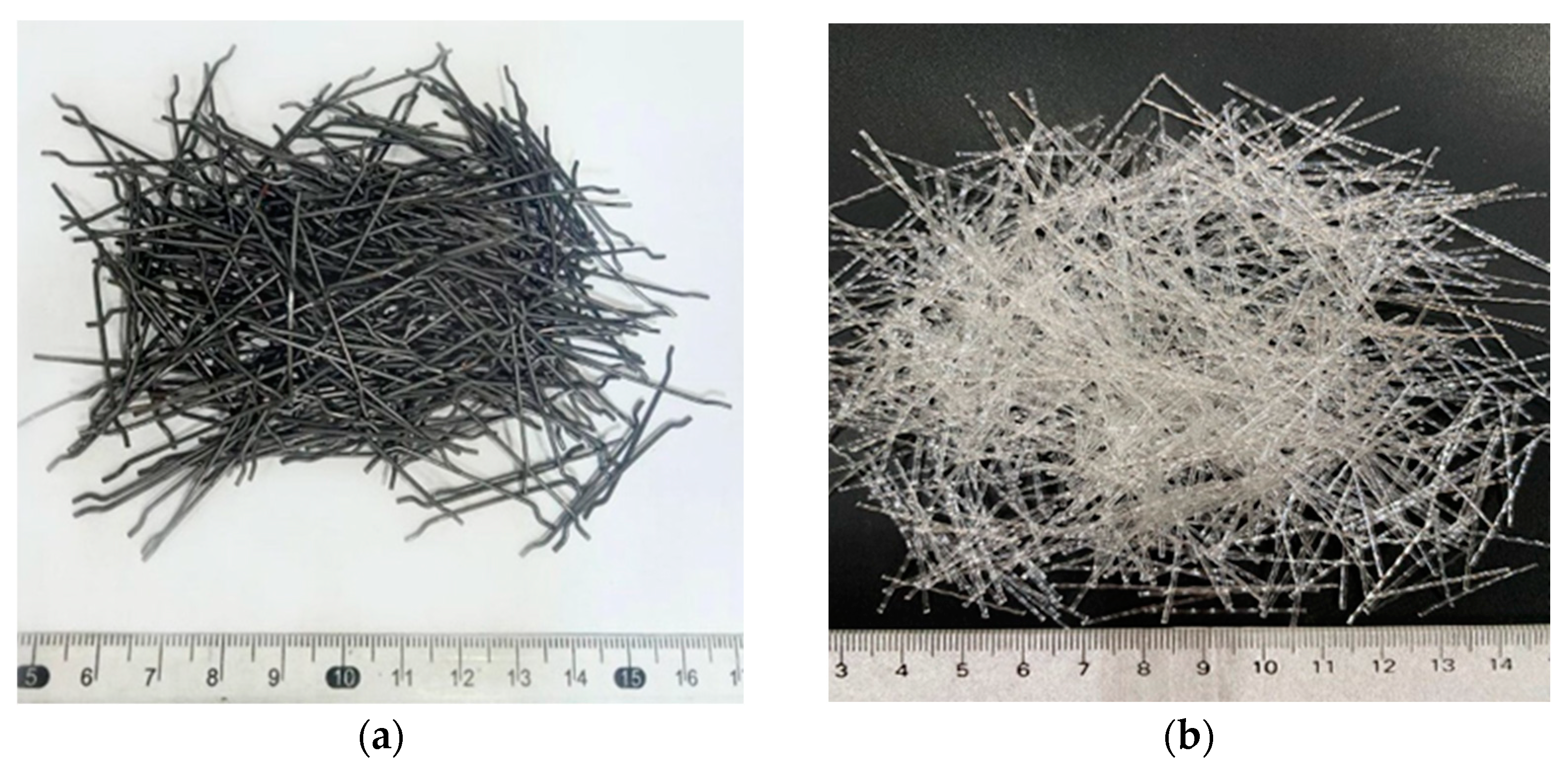
2.1. Materials

In this research, ordinary Portland cement (CEM I 52.5 N) was employed, conforming to the specifications outlined in BS EN 197-1/2011 [46]. CCB was used as a lightweight aggregate that needed several processes before using, such as washing, manual crushing, sieving, and grading, to produce coarse and finely crushed clay brick aggregates (CCBA and FCBA, respectively). Figure 1 illustrates the grading curves for CCBA and FCBA. In this context, CCBA with sizes of 4/10 was employed as coarse aggregate, and FCBA with sizes of 0.125/4 was employed as fine aggregate. The physical characteristics of both CCBA and FCBA are presented in Table 1. Additionally, silica fume was used as a partial replacement material for cement. The workability of the concrete mixes was improved by using a superplasticizer as a high-water reducer. In addition, macro synthetic PPF with a density of 910 kg/m3 and hooked SF with a density of 7870 kg/m3 were used in this investigation, as clarified in Figure 2. The physical and mechanical properties of SF and PPF are shown in Table 2 and Table 3, respectively.

2.2. Details of Reinforced Concrete Beams

To investigate the impact of fiber additives on the behavior of reinforced concrete beams, an experimental program was conducted. The program encompassed the testing of five beam specimens with a cross-sectional area of 100 × 300 mm and a length of 2000 mm. Due to the relatively large scale of the beams, only one reinforced beam was tested per variable considering the high level of care and accuracy during the preparation and testing. The five beams were prepared using five different concrete mixes, as illustrated in Table 4. The first specimen, referred to as B0, served as the control and was made using a mix of CCB. The second and third specimens, B0.1PP and B0.2PP, respectively, contained 0.1% and 0.2% PPF by volume. The fourth and fifth specimens, B0.5SF and B1.0SF, respectively, contained 0.5% and 1.0% SF by volume. All the beam specimens had the same reinforcement configuration. The longitudinal reinforcement consisted of high-tensile steel bars with a yield strength of 400 MPa and a diameter of 10 mm for the top reinforcement and 12 mm for the bottom reinforcement. The creation of stirrups involved the use of 8 mm mild steel bars with a yield strength of 308 MPa. The value of the concrete cover was taken as 25 mm and the effective depth of the beams de was equal to 275 mm. The reinforcement ratio in the longitudinal direction was 0.82% and 0.59% in the transverse direction, as illustrated in Figure 3.

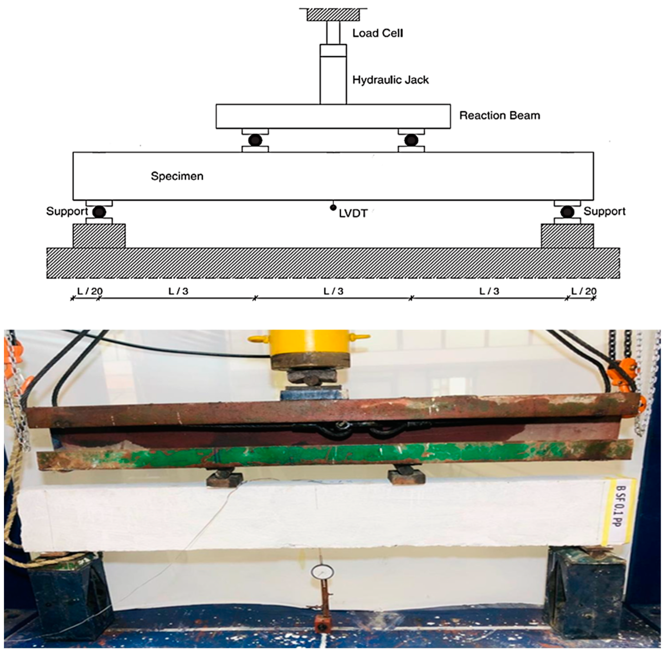
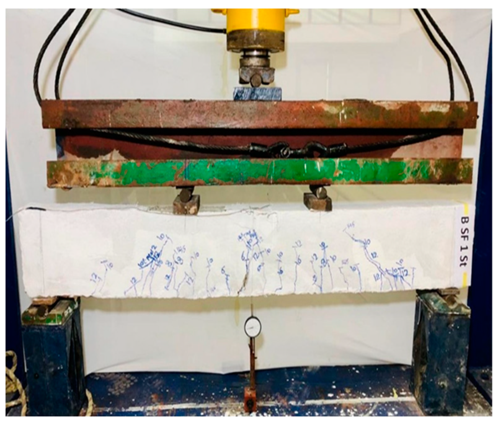
2.3. Experimental Setup

The beams were tested using a loading frame with a capacity of 100 tons. The testing was performed following the procedure described by the ASTM C39 specification [47] under a loading rate of 1 ton/min until the first crack. The beam specimens were subjected to four-point bending loading. Two 100 mm × 100 mm × 20 mm steel plates were inserted under the point loads to avoid the local crushing of concrete. Linear variable displacement transducers (LVDTs) were used to record the vertical displacements. Throughout the experiments, precise measurements were taken for the applied force and displacement at the mid-span of the beams, and the force–displacement curves were plotted. The variation of tensile strain in the steel rebar was also measured using an electrical strain gauge mounted on the steel reinforcement at the mid-span of the beam. The initiation, propagation, and widths of cracks were marked during the testing of the beams. All the beams had the same loading configuration and instrumentation system. Figure 4 shows the experimental setup of the reinforced concrete beams. While casting the reinforced concrete beams, the concrete slump of each mix was measured two times. The concrete density of each mix used to make the beams was measured on three 150 mm concrete cubes, and the concrete compressive strength of each mix was measured on six 150 mm concrete cubes. In addition, two concrete cylinders, 150 × 300 mm, were taken from each mix to measure the stress–strain behavior.

3. Results and Discussion
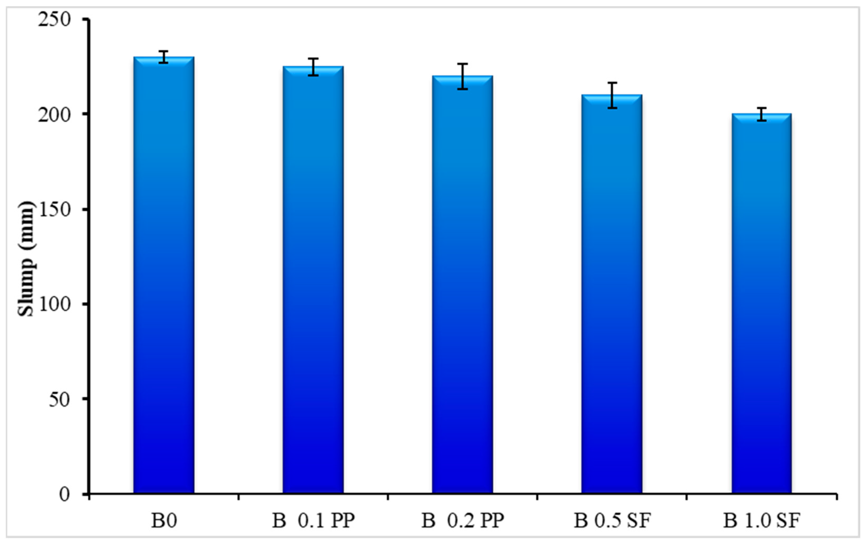
3.1. Concrete Slump

In order to assess the workability of freshly prepared lightweight concrete, slump tests were conducted in accordance with ASTM-C143 [47]. The control mix showed a slump value of 230 mm. However, the addition of SF and PPF led to a decrease in the concrete slump due to the fiber bond and cohesive nature with the concrete mixes, which reduced its flowability, as also demonstrated by the findings of Fallah and Mahdi [35], and Mohod [48]. To maintain the required slump, an extra superplasticizer was added to the mixes with the fiber content increase. As illustrated in Figure 5, adding fibers has a significant influence on concrete workability, depending on the dosage of fibers. Despite adding SP to the mixture containing 0.1% PPF (B0.1PP) and 0.2% (B0.2PP), the slump decreased by about 3% and 5%, respectively. Although a higher amount of SP was used in the mixture containing 0.5% and 1.0% SF (B0.5SF, B1.0SF) than those used in the mixtures containing 0.1% and 0.2% PPF (B0.1PP, B0.2PP), it was found that the B1.0SF concrete mix gave less workability. In general, the slump measurements of the concrete mixes varied within the range of 200 to 230 mm. The disparity in the slump between the LWC mixes containing fibers and the control concrete was negligible due to the effect of the superplasticizer utilized.

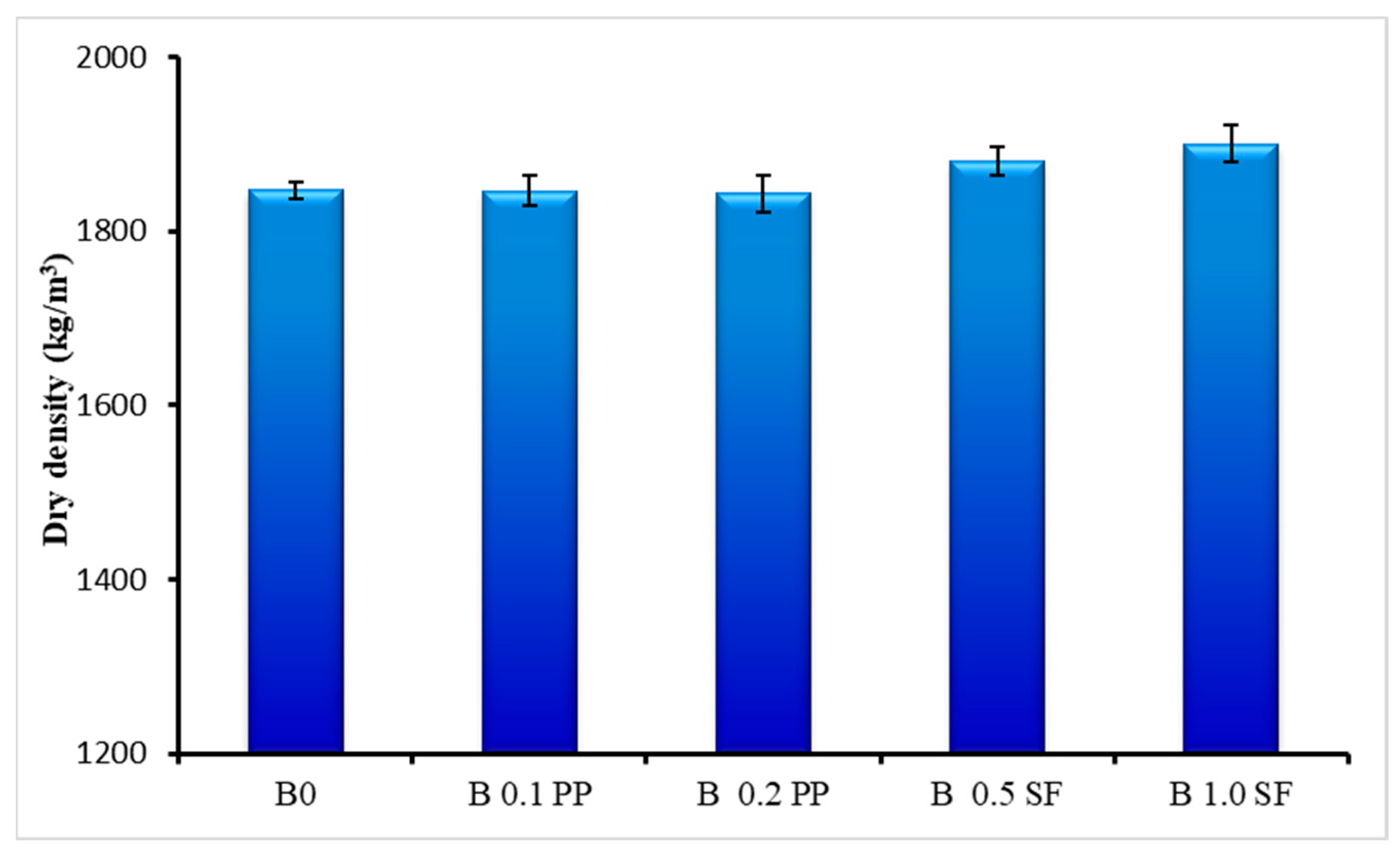
3.2. Concrete Density

Figure 6 illustrates that adding fiber to LWC results in a slight increase in the density of the produced concrete after 28 days. This observation aligns with the fact that fibers, (PPF or SF) possess a higher density compared to the control LWC. However, the density disparity between LWC mixes with varying fiber contents was relatively small. For instance, the density of fiber-free LWC measures 1847 kg/m3, as also confirmed by Atiya et al. [48], which can be categorized as lightweight aggregate concrete according to DIN 1045-1, whereas the density of LWC with 1% SF reached 1900 kg/m3. This indicates that increasing the amount of fiber has a less significant impact on the overall density of the LWC. When comparing the impact of different fiber types, it appears that SF exhibits a slightly higher density in contrast to PPF. For instance, LWC containing 0.5% SF has a density of 1880 kg/m3, whereas LWC incorporating 0.1% PPF exhibits a density of 1846 kg/m3. The incorporation of SF proves the fact that it increases the dry density of the produced concrete compared to PPF.

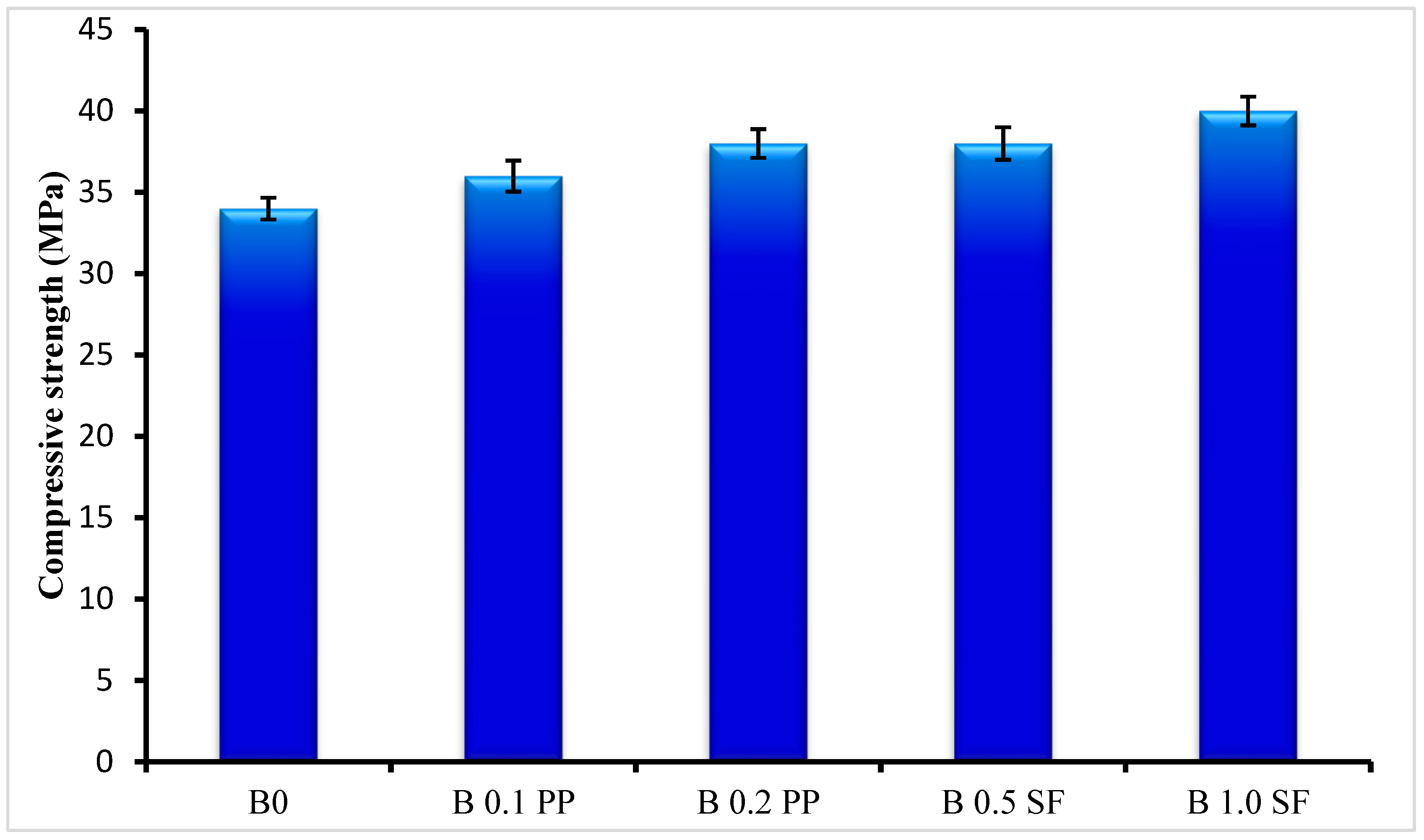
3.3. Concrete Compressive Strength

All the CCB concrete mixes showed an acceptable compressive strength compared to the conventional concrete. Figure 7 displays that when the proportion of SF and PPF increased, the compressive strength of the concrete typically increased. After 28 days, there was an observed enhancement in compressive strength, with approximately 11.7% and 17.6% noted for SF contents of 0.5% and 1.0%, respectively. Likewise, an increase in compressive strength of approximately 5.9% and 11.7% was detected after 28 days for 0.1% and 0.2% PPF contents, respectively. In the study, SF was shown to increase compressive strength in LWC more than that of PPF, as also concluded by Zohrabi et al. [49]. The increase in compressive strength seen in LWC was due to the improved mechanical bonding between the concrete matrix and the fiber. This increased binding strength helped in preventing the formation of tiny cracks. The investigation demonstrated that the addition of SF up to 1% of the concrete volume led to a significant improvement in compressive strength. This outcome aligns with the conclusions drawn from earlier research conducted by Mohod and Mohamed [48,50]. However, the results showed that the creation of air voids in the concrete mixes caused a decrease in compressive strength with the presence of larger amounts of SF. This finding is consistent with the justification introduced by Balaguru and Ramakishan [51].

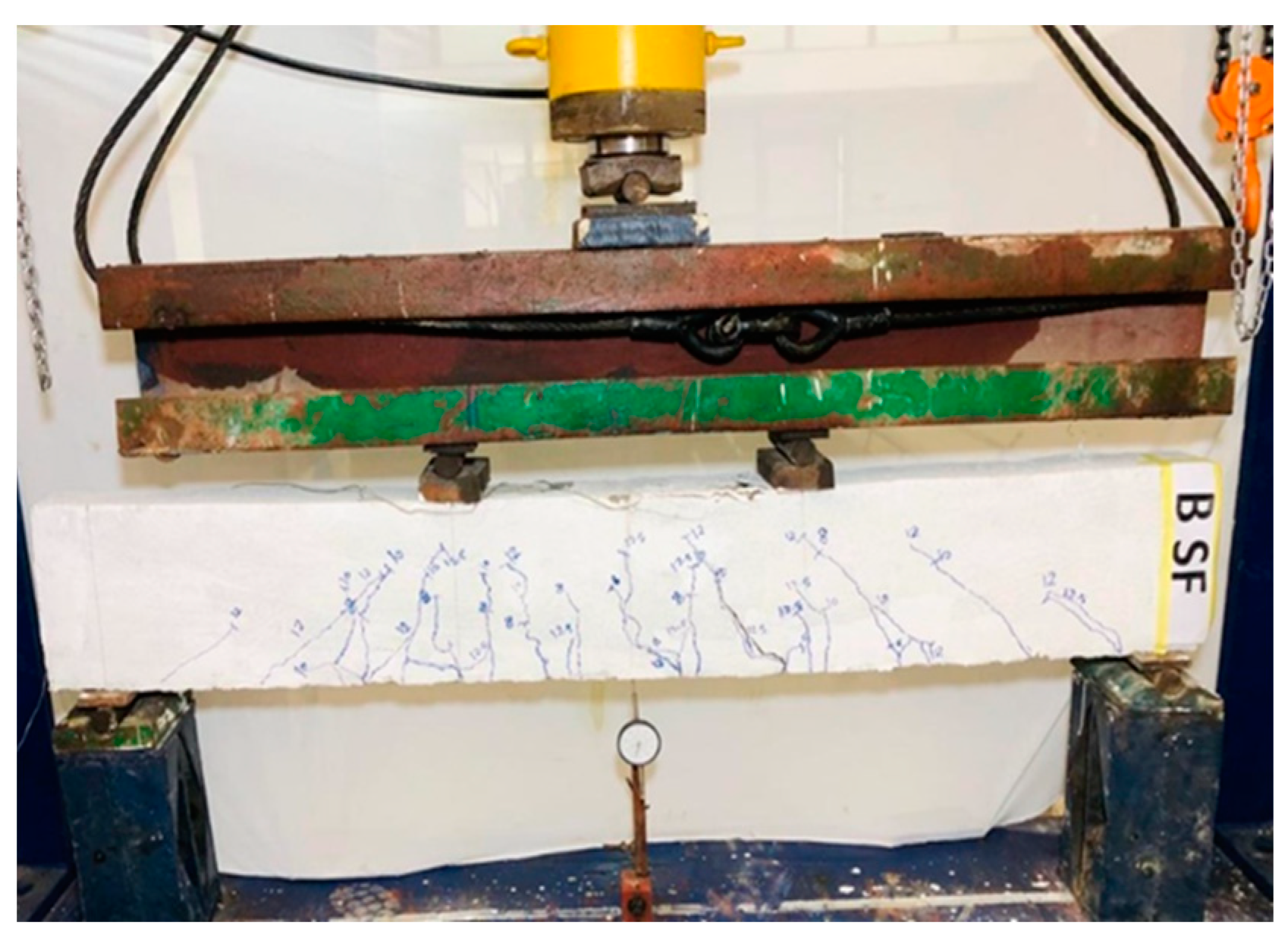
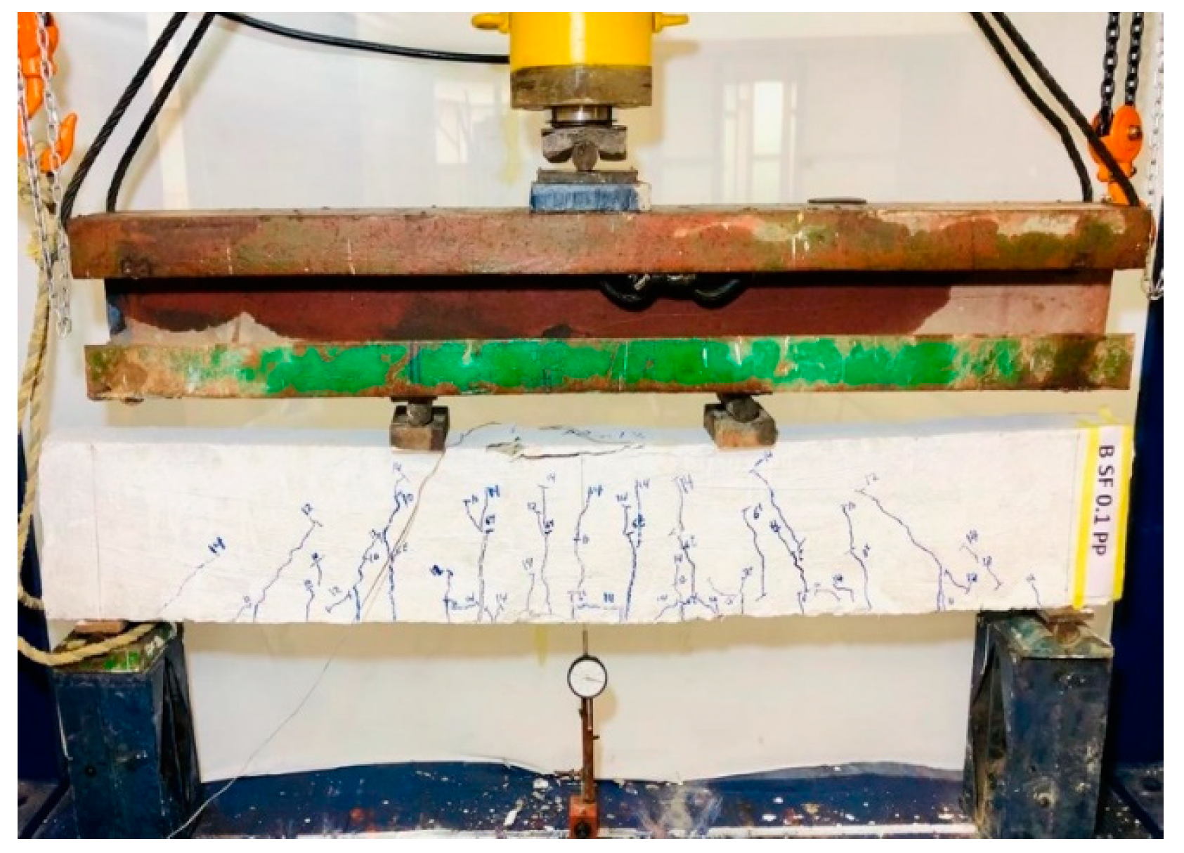
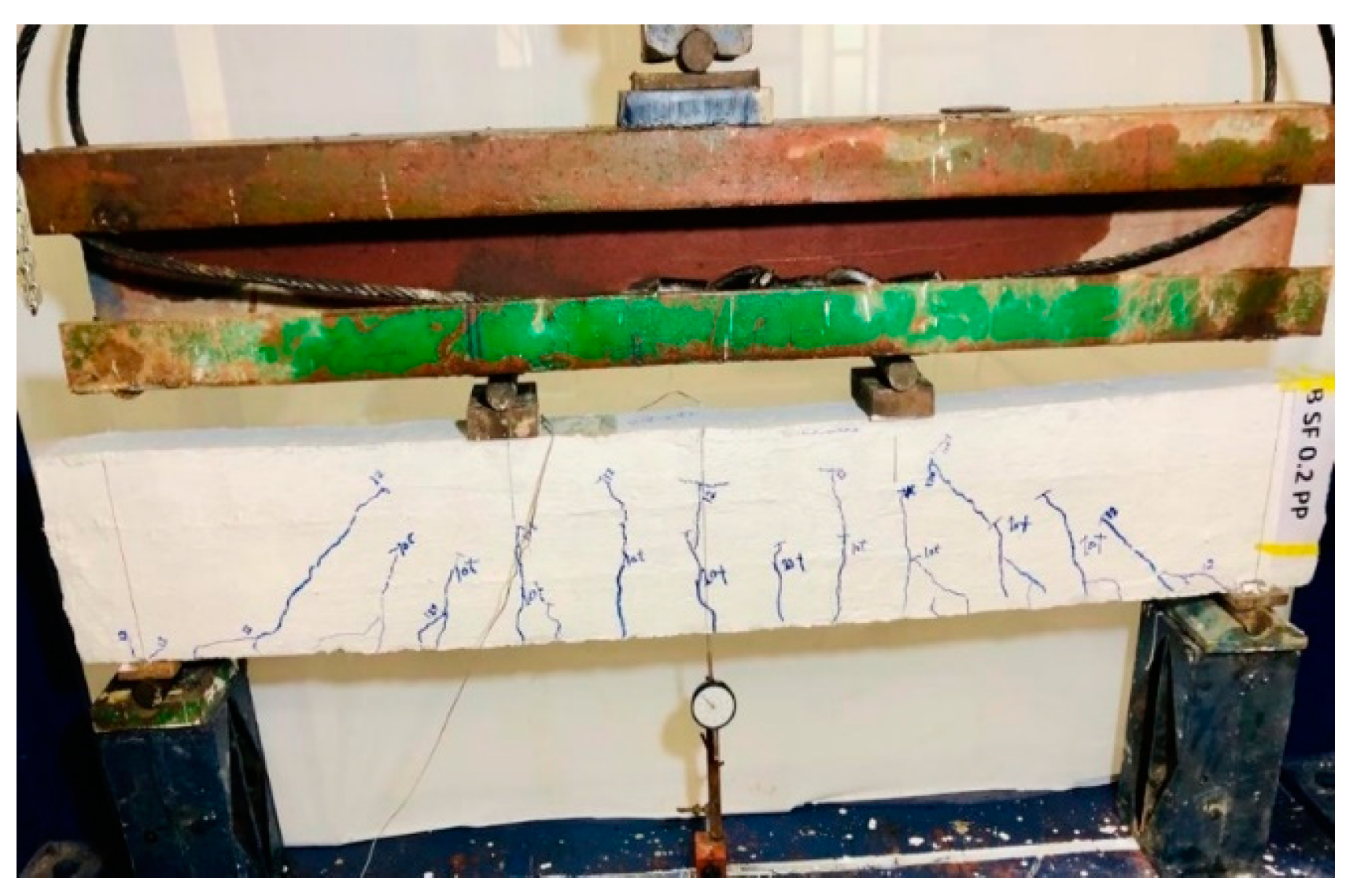
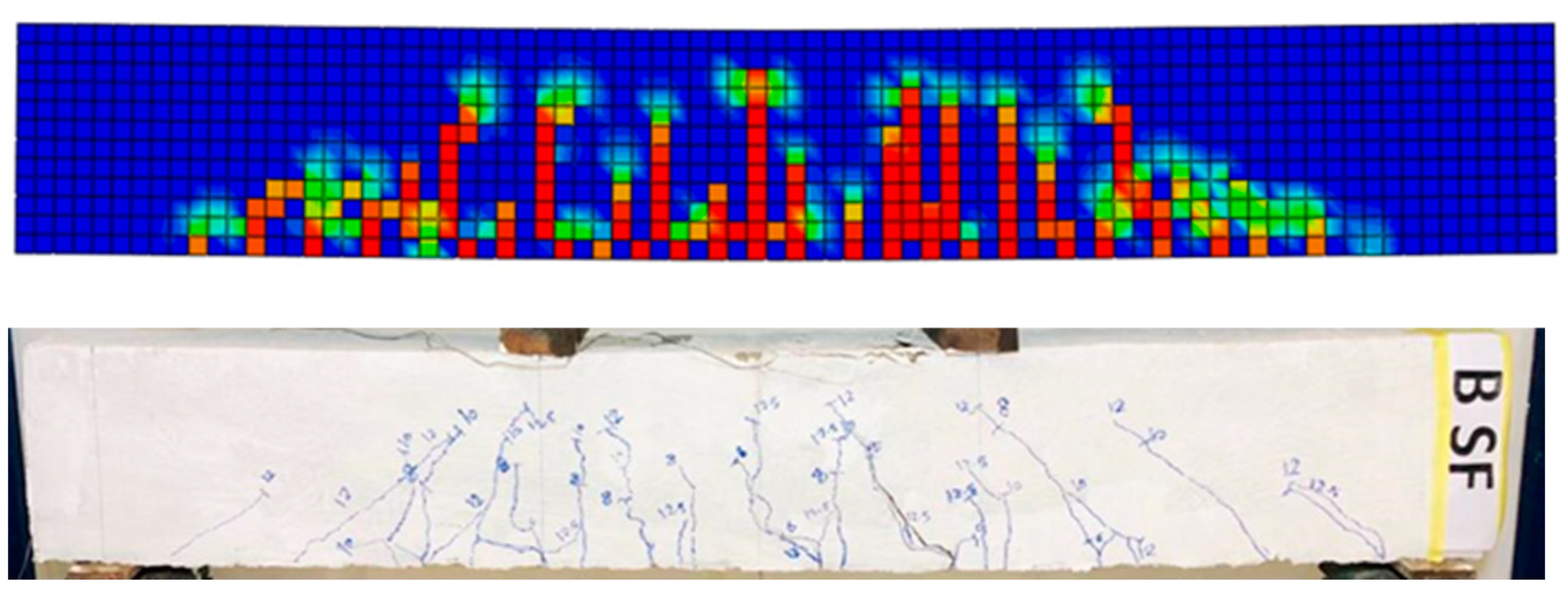
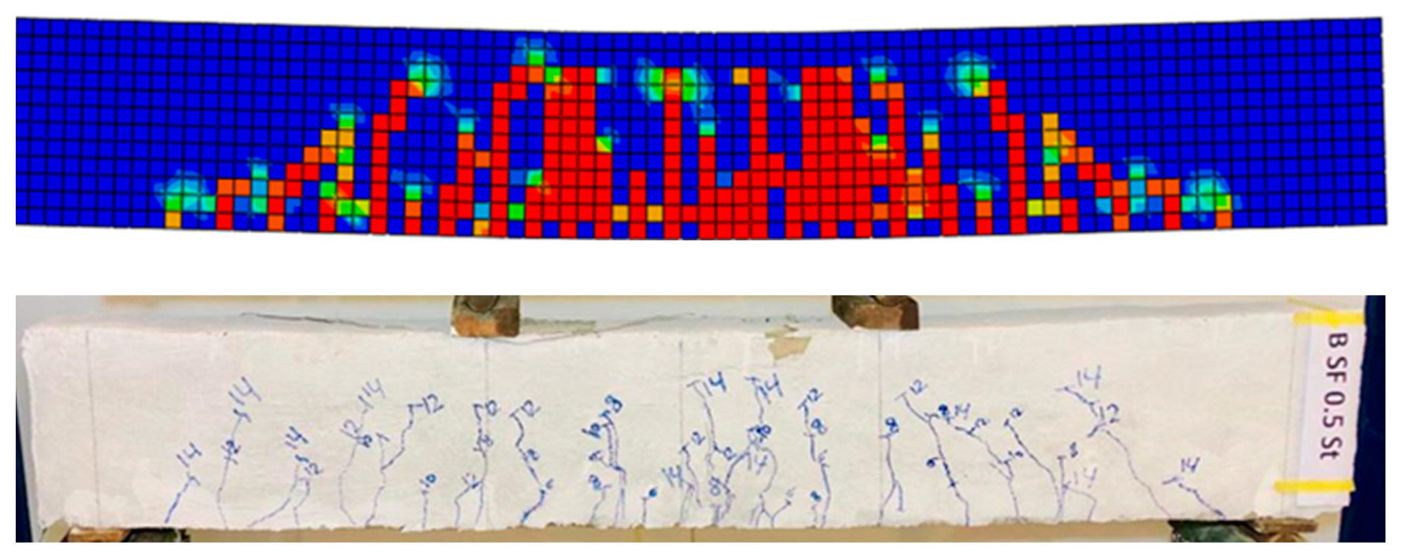
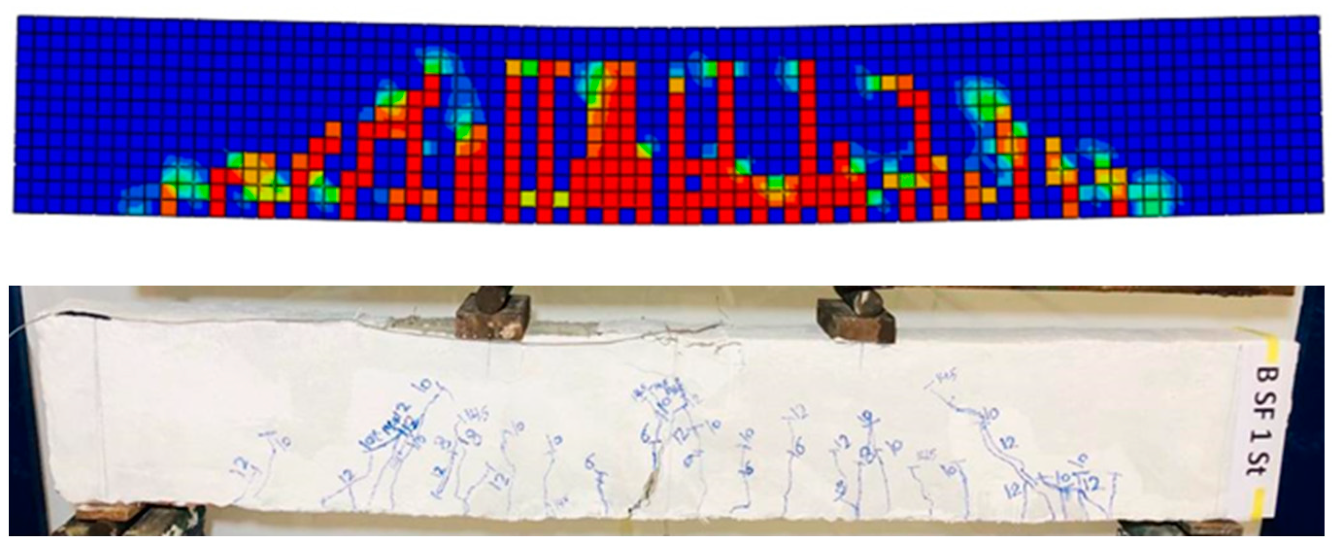
3.4. Crack Patterns and Mode of Failure of Reinforced Beams

Figure 8, Figure 9, Figure 10, Figure 11 and Figure 12 illustrate the crack patterns observed in all tested beams, highlighting the notable influence of PPF and SF on crack shape, number, and width. The failure mode for all beams, including the control beam (B0), which was a reinforced LWC beam without fiber, was flexure mode of failure. Initially, no cracks were visible, but at the 60 kN load, the first flexural crack emerged as a vertical hairline crack at the bottom of the mid-span, measuring a 0.1 mm crack width which occurred at a deflection of 0.1 mm. With the load increasing, there was a gradual rise in both the number and width of cracks, spreading towards the upper part of the beam. When the beam was subjected to a 100 kN load, the crack width measured 0.2 mm, as depicted in Figure 13, revealing both vertical and inclined cracks due to the upward shift of the neutral axis. Furthermore, the yielding of the bottom steel led to a widening of the cracks, eventually resulting in flexural failure as the load reached 125 kN.
In the case of beam B0.1PP, the initial flexural crack emerged at the bottom of the beam when the load reached 60 kN. This crack, as illustrated in Figure 12, measured 0.1 mm in width and was accompanied by inclined cracks on both sides of the beam. Flexural cracks continued propagating in the shear spans, turning inclined due to bending and shear combined effects. The beam ultimately failed in flexure at the 140 kN load, with the final crack patterns displayed in Figure 9. A comparison of crack width between BSF0.1PP and the control beam showed that the former had a smaller crack width, indicating the positive effect of adding 0.1% PPF. The integration of PPF into the concrete matrix improved material ductility and toughness, resulting in an enhanced overall performance and better control over cracks.
In the case of beam B0.2PP, the initial flexural crack was observed under a load of 80 kN, with these cracks propagating upward to the mid-span of the beam. The width of the primary crack was 0.1 mm, as demonstrated in Figure 13. The failure mode was categorized as a flexural mode of failure, characterized by the crushing of the upper concrete at the top midpoint of the beam. The ultimate load of this beam was 145 kN, signifying a notable strength enhancement. Load-crack width correlations for beam B0.2PP were showcased in Figure 10, revealing a decrease in the number of cracks within the PPF-modified beam compared to the control beam. This finding suggests that adding PPF to concrete beams can successfully reduce the development of fractures.
The initial flexural cracks in the B0.5SF and B1.0SF beams occurred at the lower section of the beams with loads of 60 kN and 80 kN, respectively, both measuring 0.05 mm in width. The beams experienced flexural failure at 140 kN and 145 kN loads for B0.5SF and B1.0SF, respectively. The ultimate crack patterns are depicted in Figure 11 and Figure 12. Comparing the crack width of the B0.5SF and B1.0SF beams to those with 0.1% and 0.2% PPF (as shown in Figure 13) revealed more narrow cracks in the former beams. These results suggest that incorporating SF in concrete beams can effectively reduce the width of flexural cracks by about 55% compared to PPF. Nevertheless, adding PPF to concrete beams offers improved crack control by reducing the number of flexural cracks.

3.5. Effect of Fiber Volume on the Load–Deflection Response of Reinforced Beams

Figure 14 illustrates the load–deflection relationships for various beams with different volumes of PPF and SF. The load corresponding to the first visible flexural crack, known as the initial cracking load, was determined and recorded in Table 5. The use of either SF or PPF delayed the initiation of the concrete cracks and increased the first load crack. Interestingly, no visible cracks appeared in the B0 beam until the load reached 60 kN, where a vertical hairline crack was noticed at the bottom of its mid-span. In particular, when compared to the control beam, the B1.0SF and B0.2PP beams showed a 33.3% enhancement in their first crack loads. This indicates an improvement in the compressive strength of the developed concrete. On the other hand, the B0.1PP and B0.5SF beams displayed initial cracking loads equivalent to that of the reference beam. Table 5 presents the maximum yield load in the beam reinforced with 1.0% SF (beam B1.0SF), which is increased by 22.2% compared to the control beam. This observation shows that using 1.0% SF is the best in this study to enhance the yield loads of the CCB concrete mix for fabricating reinforced concrete beams, despite the convergence of results when compared to PPF. Furthermore, the maximum load enhancement varies from 8% to 16% in the beams that contain different amounts of fiber, in comparison to the control beam, and the maximum load is 145 kN for the B1.0 SF beam.
As shown in Figure 14, it can be observed that there was an appreciable increase in deflection as a result of the PPF addition and the maximum deflection in all tested beams was found in beam B0.1PP. The ductility of B0.1PP, incorporating 0.1% PPF, exhibited a 20% rise in comparison to the control beam. Conversely, the ductility of B0.5SF with 0.5% SF caused a reduction of 18.0% compared to the control beam. Therefore, the enhanced ductility of the beam is attributed to the nature of the failure mode of concrete containing PPF. After cracking concrete under stress, the existence of PPF acted as a bridge across the cracked concrete. This is followed by a relatively high elongation of PPF, and the beam fails as a result of concrete crushing at the top center of the beam. In general, there is an enhancement in beam ductility as a result of the addition of PPF to CCB concrete.

3.6. Steel Reinforcement Strains

The relationship between the strain in the bottom steel and the applied load is plotted in Figure 15. The observed reinforcement strain was very small, and the load–strain relationship was almost linear elastic prior to the first crack. Until the first crack, the beam acted like a simple concrete beam with no reinforcement. The behavior of the steel strain changed after the cracking of the beams. A considerable increase in strains of the longitudinal steel reinforcement was noted with a quiet increase in loads after the first crack. These findings suggest that the addition of both PPF and SF to LWC did not significantly affect the steel strain under the applied load. Moreover, at the same load level, beams with higher fiber content exhibited lower reinforcement strains. To illustrate this, using PPF with 0.2% (B0.2PP) was more effective than 0.1% (B0.1PP), and adding SF by 1.0% (B1.0SF) has a more significant influence than 0.5% (B0.5SF). However, all beams showed clear yielding of the steel bars.

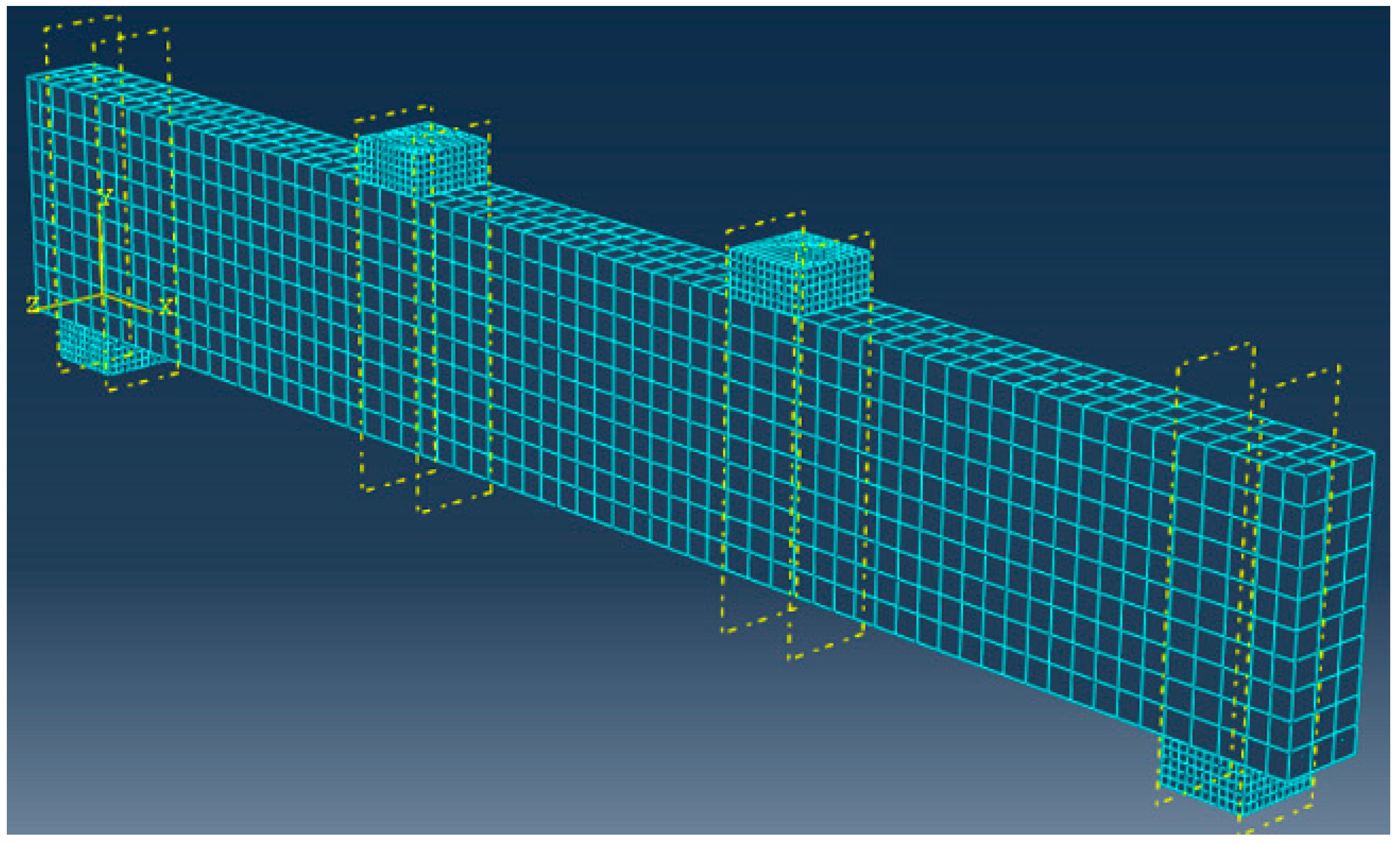
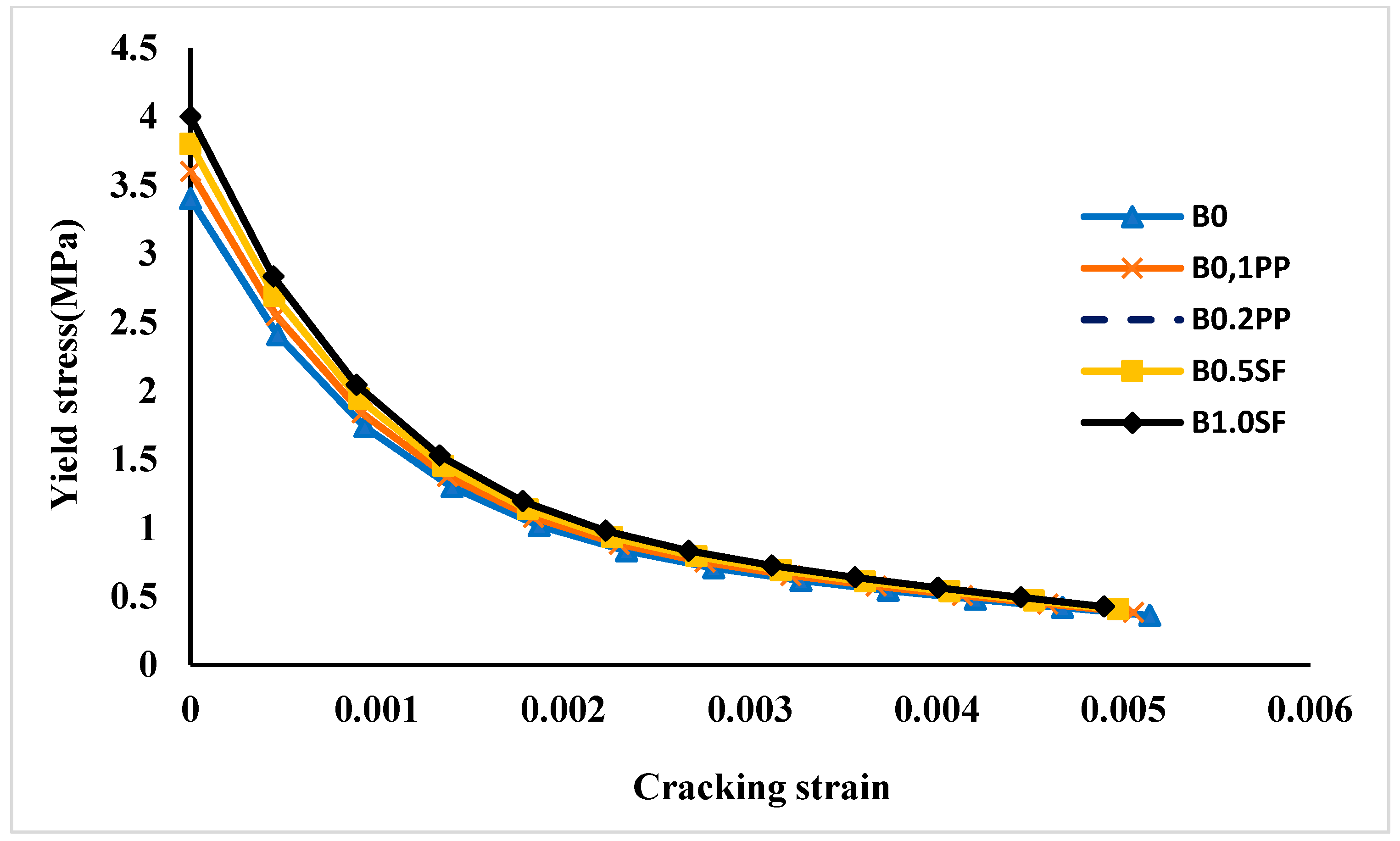
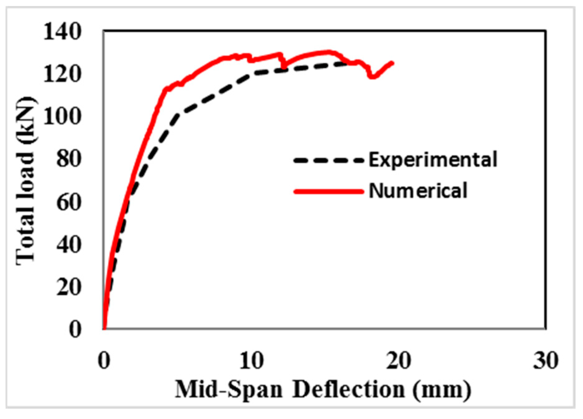
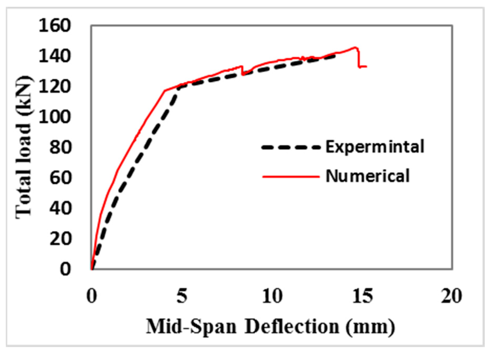
4. Numerical Analysis

The ABAQUS 16.4 computer program is used to simulate the structural behavior of lightweight reinforced concrete beams made of CCB using a three-dimensional nonlinear finite elements model. The concrete is modeled using the SOLID C3D8R element, which is capable of exhibiting tension-induced cracking and compression-induced crushing. To depict the primary and web reinforcement, the concrete solid 65 element employs a bar element (T2D3), presumed to be uniformly distributed within the solid element. The meshing of each specimen is tailored according to the specific reinforcement dimensions. In order to choose the optimum mesh size for the finite elements model, a mesh sensitivity analysis was carried out using element sizes in the order of 5, 10, 15, 20, and 25 mm. The best fit to the experimental results considering the explicit time integration solution was achieved using the element size of 25 mm. This mesh element size was also recommended and used in many previous research [52]. Detailed insights into the finite element modeling of both concrete and steel reinforcement can be located in the ABAQUS program manual [53]. Figure 16 shows a visual representation of the finite element meshing applied in the modeling of the current beams.
In the finite element modeling, a complete bond is assumed to be perfect between the concrete and reinforcement. Additionally, a Poisson’s ratio of 0.3 is assumed for steel, coupled with an elasticity modulus (Es) of 200 GPa. The compressive strength ( f c ) of the concrete is related to its modulus of elasticity (Ec), which is calculated using the empirical equation E c = 4700 f c [54]. For the tested control beam with fcu equal to 34 MPa, the adopted value of Ec is equal to 28,582 MPa. A Poisson’s ratio of 0.20 is also assumed for the concrete material. The uniaxial stress–strain curves of concrete mixes used in the tested beams were measured. The inelastic strain εcin was calculated from the total compressive strain εc using the following equation:
ε c i n = ε c ε o c e l
where εocel = ( σc/Eo), εocel is the compressive elastic strain corresponding to the undamaged material. The cracking strain εtcr can be calculated from the total tensile strain εt by using the following equation:
ε t c r = ε t ε o t e l
where εotel = ( σc/Eo), εotel is the tensile elastic strain corresponding to the undamaged material. The inelastic strain in compression and the cracking strain in tension are illustrated in Figure 17 and Figure 18, which were used in the numerical simulations. The plasticity parameters for the constitutive model behavior are given in Table 6. The damage parameter was determined using the empirical equations d c = 1 σ c σ c u for compression damage and d t = 1 σ t σ t u for tension damage.
Loading and boundary conditions were performed in the model of the beam to simulate the experimental test setup, as shown in Figure 4 for all tested beams. In the beams tested under flexure, the two edges of the beam were roller supports to allow rotation at both ends of the beam u 1 = 0.0 but u 2 and u 3 ≠ 0.0.
The load–deflection curves obtained from the experimental and finite element modeling for all beams are compared in Figure 19, Figure 20, Figure 21, Figure 22 and Figure 23. The outcomes indicate that the nonlinear finite element model effectively predicts the ultimate load and mid-span deflection behavior of the tested beams. The average ratio of experimental to numerical loads for CCB concrete beams equals 0.986, while the average ratio of experimental to numerical mid-span deflections equals 0.997. This finding highlights the effectiveness of the FEM in simulating the structural response of lightweight reinforced concrete beams made of CCB when subjected to various loading conditions. From that, the FEM can be used to predict the behavior of CCB concrete beams, such as the distribution of stress and strain, and tensile damage distribution that is presented in Figure 24, Figure 25, Figure 26, Figure 27 and Figure 28 with the corresponding ones from the experimental testing.

5. Conclusions

In this research, the use of CCB as coarse and fine aggregates in concrete and the effects of SF and PPF on the mechanical behavior of lightweight reinforced concrete beams were investigated. Load capacity, failure mechanism, and ductility were measured for a total of five RC beams. The following key points can be drawn from the results of this study.
  • LWC beams exhibited a considerable amount of deflection, which provided enough warning before failure. Moreover, the ductility of LWC beams was higher than that of normal-weight concrete beams.
  • When PPF was added to LWC by up to 0.2% by volume, the ultimate load and displacement ductility significantly improved compared to fiberless LWC beams by about 16% and 24.7%, respectively.
  • With the addition of 0.5% and 1.0% SF, the compressive strength of the LWC beams increased by approximately 11.8% and 17.6%, respectively, after 28 days. Similarly, 0.1% PPF and 0.2% PPF increased the compressive strength after 28 days by approximately 5.9% and 11.8%, respectively.
  • Compared to the control beam, the ultimate load of all fiber-reinforced beams increased by an average of 16%. SF outperformed PPF in terms of effectiveness at reducing flexural cracks and enhancing crack control.
  • The ductility of the beam was greatly improved by 20% when 0.1% PPF was added compared to the control beam, whereas 18% was lost when 0.5% SF was added.
  • The numerical model’s results showed strong agreement with the experimental results, indicating that it might replace laboratory experiments in future studies.
Overall, there is a promising potential use of CCB as a sustainable approach in the concrete construction industry to produce structural lightweight and environmentally friendly concrete. It is recommended for future studies to use different proportions of PPF and SF in CCB concrete for more sustainable structural systems.

Author Contributions

Conceptualization, E.A.E. and M.A.E.; data curation, O.Y.; formal analysis, E.A.E. and M.A.E.; investigation, E.A.E., O.Y. and M.A.E.; methodology, E.A.E., M.M., M.A.E. and M.E.E.M.; project administration, O.Y.; resources, M.M. and M.E.E.M.; software, E.A.E. and M.E.E.M.; supervision, M.M., M.A.E. and M.E.E.M.; validation, M.M. and M.E.E.M.; writing—original draft, E.A.E. and M.E.E.M.; writing—review and editing, M.M., O.Y. and M.A.E. All authors have read and agreed to the published version of the manuscript.

Funding

This research received no external funding.

Data Availability Statement

All data used in this research have been presented in the manuscript. No other source is needed.

Conflicts of Interest

The authors declare no conflict of interest.

References

  1. Narayanan, N.; Ramamurthy, K. Structure and properties of aerated concrete: A review. Cem. Concr. Compos. 2000, 22, 321–329. [Google Scholar] [CrossRef]
  2. Eltayeb, E.; Ma, X.; Zhuge, Y.; Xiao, J.; Youssf, O. Composite walls Composed of profiled steel skin and foam rubberized concrete subjected to eccentric compressions. J. Build. Eng. 2021, 46, 103715. [Google Scholar] [CrossRef]
  3. Eltayeb, E.; Ma, X.; Zhuge, Y.; Youssf, O.; Mills, J.E.; Xiao, J.; Singh, A. Structural performance of composite panels made of profiled steel skins and foam rubberised concrete under axial compressive loads. Eng. Struct. 2020, 211, 110448. [Google Scholar] [CrossRef]
  4. Sari, D.; Pasamehmetoglu, A.G. The effects of gradation and admixture on the pumice lightweight aggregate concrete. Cem. Concr. Res. 2005, 35, 936–942. [Google Scholar]
  5. Youssf, O.; ElGawady, M. An overview of sustainable concrete made with scrap rubber. In Proceedings of the 22nd Australasian Conference on the Mechanics of Structures and Materials ACMSM 22, Sydney, NSW, Australia, 11–14 December 2012; pp. 1039–1044. [Google Scholar] [CrossRef]
  6. Satish, C.; Berntsson, L. Lightweight Aggregate Concrete; Elsevier: Amsterdam, The Netherlands, 2002. [Google Scholar]
  7. Mostafa, S.A.; Faried, A.S.; Farghali, A.A.; El-Deeb, M.M.; Tawfik, T.A.; Majer, S.; Abd Elrahman, M. Influence of nanoparticles from waste materials on mechanical properties, durability and microstructure of UHPC. Materials 2020, 13, 4530. [Google Scholar]
  8. Younis, M.; Amin, M.; Tahwia, A.M. Durability and mechanical characteristics of sustainable self-curing concrete utilizing crushed ceramic and brick wastes. Case Stud. Constr. Mater. 2022, 17, e01251. [Google Scholar] [CrossRef]
  9. Yi, O.; Zhuge, Y.; Ma, X.; Gravina, R.J.; Mills, J.E.; Youssf, O. Push-off and Pull-out Bond Behaviour of CRC Composite Slabs—An Experimental Investigation. Eng. Struct. 2020, 228, 111480. [Google Scholar] [CrossRef]
  10. Tam, V.W.Y.; Soomro, M.; Evangelista, A.C.J. A review of recycled aggregate in concrete applications (2000–2017). Constr. Build. Mater. 2018, 172, 272–292. [Google Scholar] [CrossRef]
  11. Hansen, T. Recycling of Demolished Concrete and Masonry; CRC Press: Boca Raton, FL, USA, 2004. [Google Scholar]
  12. Kumutha, R.; Vijai, K. Strength of concrete incorporating aggregates recycled from demolition waste. ARPN J. Eng. Appl. Sci. 2010, 5, 64–71. [Google Scholar]
  13. Debieb, F.; Kenai, S. The use of coarse and fine crushed bricks as aggregate in concrete. Constr. Build. Mater. 2008, 22, 886–893. [Google Scholar] [CrossRef]
  14. Liu, Q.; Li, B.; Xiao, J.; Singh, A. Utilization potential of aerated concrete block powder and clay brick powder from C&D waste. Constr. Build. Mater. 2019, 238, 117721. [Google Scholar] [CrossRef]
  15. Cachim, P.B. Mechanical properties of brick aggregate concrete. Constr. Build. Mater. 2009, 23, 1292–1297. [Google Scholar] [CrossRef]
  16. Zheng, C.; Lou, C.; Du, G.; Li, X.; Liu, Z.; Li, L. Mechanical properties of recycled concrete with demolished waste concrete aggregate and clay brick aggregate. Results Phys. 2018, 9, 1317–1322. [Google Scholar] [CrossRef]
  17. Zhao, Y.; Gao, J.; Chen, F.; Liu, C.; Chen, X. Utilization of waste clay bricks as coarse and fine aggregates for the preparation of lightweight aggregate concrete. J. Clean. Prod. 2018, 201, 706–715. [Google Scholar] [CrossRef]
  18. Adem, H.; Athab, E.; Thamer, S.; Jasim, A. The behavior of Lightweight Aggregate Concrete Made with Different Types of Crushed Bricks. IOP Conf. Ser. Mater. Sci. Eng. 2019, 584, 012040. [Google Scholar] [CrossRef]
  19. Ali, Y.M.S. Effect of Silica Fume on the Behavior of Lightweight RC Beams Made from Crushed Bricks; Springer: Berlin/Heidelberg, Germany, 2022. [Google Scholar]
  20. Aliabdo, A.A.; Abd-Elmoaty, A.-E.M.; Hassan, H.H. Utilization of crushed clay brick in concrete industry. Alex. Eng. J. 2014, 53, 151–168. [Google Scholar] [CrossRef]
  21. Helmy, S.H.; Tahwia, A.M.; Mahdy, M.G.; Elrahman, M.A.; Abed, M.A.; Youssf, O. The Use of Recycled Tire Rubber, Crushed Glass, and Crushed Clay Brick in Lightweight Concrete Production: A Review. Sustainability 2023, 15, 10060. [Google Scholar] [CrossRef]
  22. Duan, Z.; Hou, S.; Xiao, J.; Singh, A. Rheological properties of mortar containing recycled powders from construction and demolition wastes. Constr. Build. Mater. 2019, 237, 117622. [Google Scholar] [CrossRef]
  23. Mobili, A.; Giosuè, C.; Corinaldesi, V.; Tittarelli, F. Bricks and Concrete Wastes as Coarse and Fine Aggregates in Sustainable Mortars. Adv. Mater. Sci. Eng. 2018, 2018, 8676708. [Google Scholar] [CrossRef]
  24. Wongsa, A.; Sata, V.; Nuaklong, P.; Chindaprasirt, P. Use of crushed clay brick and pumice aggregates in lightweight geopolymer concrete. Constr. Build. Mater. 2018, 188, 1025–1034. [Google Scholar] [CrossRef]
  25. Yang, J.; Du, Q.; Bao, Y. Concrete with recycled concrete aggregate and crushed clay bricks. Constr. Build. Mater. 2011, 25, 1935–1945. [Google Scholar] [CrossRef]
  26. Madandoust, R.; Kazemi, M.; Yousefi Moghadam, S. Analytical study on tensile strength of concrete. Rev. Romana De Mater. 2017, 47, 204. [Google Scholar]
  27. Toufigh, V.; Abyaneh, M.J.; Jafari, K. Study of Behavior of Concrete under Axial and Triaxial Compression. ACI Mater. J. 2017, 114, 619. [Google Scholar] [CrossRef]
  28. Hassanli, R.; Youssf, O.; Vincent, T.; Mills, J.E.; Manalo, A.; Gravina, R. Experimental study on compressive behavior of FRP-confined expansive rubberized concrete. J. Compos. Constr. 2020, 24, 04020034. [Google Scholar]
  29. Li, J.; Niu, J.; Wan, C.; Liu, X.; Jin, Z. Comparison of flexural property between high performance polypropylene fiber reinforced lightweight aggregate concrete and steel fiber reinforced lightweight aggregate concrete. Constr. Build. Mater. 2017, 157, 729–736. [Google Scholar] [CrossRef]
  30. Sadrmomtazi, A.; Tahmouresi, B.; Saradar, A. Effects of silica fume on mechanical strength and microstructure of basalt fiber reinforced cementitious composites (BFRCC). Constr. Build. Mater. 2018, 162, 321–333. [Google Scholar] [CrossRef]
  31. Saradar, A.; Tahmouresi, B.; Mohseni, E.; Shadmani, A. Restrained Shrinkage Cracking of Fiber-Reinforced High-Strength Concrete. Fibers 2018, 6, 12. [Google Scholar] [CrossRef]
  32. Yousefi Moghadam, S.; Ranjbar, M.M.; Madandoust, R.; Kazemi, M. Analytical study on the behavior of corrosion-damaged reinforced concrete beams strengthen with FRP. Rev. Romana De Mater. 2017, 47, 514–521. [Google Scholar]
  33. Aulia, T.B. Effects of Polypropylene Fibers on the Properties of High-Strength Concretes; Institutes for Massivbau and Baustoffechnologi, University Leipzig: Saxony, Germany, 2002; Volume 7. [Google Scholar]
  34. Banthia, N.; Gupta, R. Influence of polypropylene fiber geometry on plastic shrinkage cracking in concrete. Cem. Concr. Res. 2006, 36, 1263–1267. [Google Scholar] [CrossRef]
  35. Fallah, S.; Nematzadeh, M. Mechanical properties and durability of high-strength concrete containing macro-polymeric and polypropylene fibers with nano-silica and silica fume. Constr. Build. Mater. 2017, 132, 170–187. [Google Scholar] [CrossRef]
  36. Yan, H.; Sun, W.; Chen, H. The effect of silica fume and steel fiber on the dynamic mechanical performance of high-strength concrete. Cem. Concr. Res. 1999, 29, 423–426. [Google Scholar] [CrossRef]
  37. Balendran, R.; Zhou, F.; Nadeem, A.; Leung, A. Influence of steel fibres on strength and ductility of normal and lightweight high strength concrete. J. Affect. Disord. 2002, 37, 1361–1367. [Google Scholar] [CrossRef]
  38. Habel, K.; Gauvreau, P. Response of ultra-high performance fiber reinforced concrete (UHPFRC) to impact and static loading. Cem. Concr. Compos. 2008, 30, 938–946. [Google Scholar] [CrossRef]
  39. Shafigh, P.; Mahmud, H.; Jumaat, M.Z. Effect of steel fiber on the mechanical properties of oil palm shell lightweight concrete. Mater. Des. 2011, 32, 3926–3932. [Google Scholar] [CrossRef]
  40. Hassanpour, M.; Shafigh, P.; Bin Mahmud, H. Mechanical Properties of Structural Lightweight Aggregate Concrete Containing Low Volume Steel Fiber. Arab. J. Sci. Eng. 2014, 39, 3579–3590. [Google Scholar] [CrossRef]
  41. Ramadevi, K.; Venkatesh, B.D.L. Flexural Behavior of Hybrid (Steel-Polypropylene) Fiber Reinforced Concrete Beams. Eur. J. Sci. Res. 2012, 70, 81–87. [Google Scholar]
  42. Prasad, M.; Rajeev, C.; Rakesh, G. A comparative study of polypropylene fibre reinforced silica fume concrete with plain cement concrete. Int. J. Eng. Res. Sci. Technol. 2013, 2, 127–136. [Google Scholar]
  43. Thirumurugan, S.; Sivakumar, A. Compressive strength index of crimped polypropylene fibres in high strength cementitious matrix. World Appl. Sci. J. 2013, 24, 698–702. [Google Scholar]
  44. Jusoh, W.A.; Ibrahim, I.S.; Sam, A.R. Flexural behaviour of reinforced concrete beams with discrete steel–polypropylene fibres. In MATEC Web of Conferences; EDP Sciences: Les Ulis, France, 2017; Volume 101. [Google Scholar]
  45. Peng, Z.; Qingfu, L. Fracture Properties of Polypropylene Fiber Reinforced Concrete Containing Fly Ash and Silica Fume. Res. J. Appl. Sci. Eng. Technol. 2013, 5, 665–670. [Google Scholar]
  46. Sanjuán, M.A.; Argiz, C. The new European standard on common cements specifications EN 197-1: 2011. Mater. De Construcción 2012, 62, 425–430. [Google Scholar] [CrossRef]
  47. Standard, A. Standard Test Method for Slump of Hydraulic-Cement Concrete; ASTM Annual Book of ASTM Standards; ASTM Standards: West Conshohocken, PA, USA, 2015. [Google Scholar]
  48. Mohod, M.V. Performance of steel fiber reinforced concrete. Int. J. Eng. Sci. 2012, 1, 1–4. [Google Scholar]
  49. Zohrabi, M.; Zohrabi, A.; Chermahini, A.G. Investigation of the mechanical properties of lightweight concrete containing LECA with Metakaoline Pozzolan using polypropylene and steel fibers. J. Appl. Environ. Biol. Sci. 2015, 5, 11–15. [Google Scholar]
  50. Mohamed, A.M.; Tayeh, B.A.; Abu Aisheh, Y.I.; Salih, M.N.A. Exploring the performance of steel fiber reinforced lightweight concrete: A case study review. Case Stud. Constr. Mater. 2023, 18, e01968. [Google Scholar] [CrossRef]
  51. Balaguru, P.; Ramakrishnan, V.J.M.J. Properties of fiber reinforced concrete: Workability, behavior under long-term loading, and air-void characteristics. Mater. J. 1988, 85, 189–196. [Google Scholar]
  52. Albu-Hassan, N.H.; Al-Thairy, H. Experimental and numerical investigation on the behavior of hybrid concrete beams reinforced with GFRP bars after exposure to elevated temperature. Structures 2020, 28, 537–551. [Google Scholar] [CrossRef]
  53. Smith, M. ABAQUS/Standard User’s Manual, Version 6.9; Dassault Systèmes Simulia Corp: Providence, RI, USA, 2009. [Google Scholar]
  54. ACI 318-14; Building Code Requirements for Structural Concrete. ACI (American Concrete Institute): Farmington Hills, MI, USA, 2014.
Figure 1. Grading curves of both coarse and finely crushed clay brick aggregates.
Sustainability 15 14570 g001
Figure 2. Fibers employed in the experimental investigation: (a) SF and (b) PPF.
Sustainability 15 14570 g002
Figure 3. Dimensions and reinforcement details of the tested concrete beams.
Sustainability 15 14570 g003
Figure 4. Experimental setup of the reinforced concrete beams.
Sustainability 15 14570 g004
Figure 5. Slump values of the produced concrete.
Sustainability 15 14570 g005
Figure 6. Dry density of the produced concrete at 28 days.
Sustainability 15 14570 g006
Figure 7. Compressive strength of the produced concrete at 28 days.
Sustainability 15 14570 g007
Figure 8. Crack patterns of beam B0.
Sustainability 15 14570 g008
Figure 9. Crack patterns of beam B0.1PP.
Sustainability 15 14570 g009
Figure 10. Crack patterns of beam B0.2PP.
Sustainability 15 14570 g010
Figure 11. Crack patterns of beam B0.5SF.
Sustainability 15 14570 g011
Figure 12. Crack patterns of beam B1.0SF.
Sustainability 15 14570 g012
Figure 13. Comparison of the crack width for all tested beams.
Sustainability 15 14570 g013
Figure 14. Load–deflection relationship of the tested beams.
Sustainability 15 14570 g014
Figure 15. Relationship between applied load and bottom reinforcement strain.
Sustainability 15 14570 g015
Figure 16. Typical finite element mesh for the tested beams with the loading and support locations.
Sustainability 15 14570 g016
Figure 17. Stress–strain curves in compression for the tested beams.
Sustainability 15 14570 g017
Figure 18. Stress–strain curves in tension for the tested beams.
Sustainability 15 14570 g018
Figure 19. Control beam (B0) load–mid-span deflection curves.
Sustainability 15 14570 g019
Figure 20. Beam B0.5SF load–mid-span deflection curves.
Sustainability 15 14570 g020
Figure 21. Beam B1.0SF load–mid-span deflection curves.
Sustainability 15 14570 g021
Figure 22. Beam B0.1PP load–mid-span deflection curves.
Sustainability 15 14570 g022
Figure 23. Beam B0.2PP load–mid-span deflection curves.
Sustainability 15 14570 g023
Figure 24. Numerical and experimental tensile damage distribution for control beam B0.
Sustainability 15 14570 g024
Figure 25. Numerical and experimental tensile damage distribution for beam B0.1PP.
Sustainability 15 14570 g025
Figure 26. Numerical and experimental tensile damage distribution for beam B0.2PP.
Sustainability 15 14570 g026
Figure 27. Numerical and experimental tensile damage distribution for beam B0.5SF.
Sustainability 15 14570 g027
Figure 28. Numerical and experimental tensile damage distribution for beam B1.0SF.
Sustainability 15 14570 g028
Table 1. Physical characteristics of CCBA and FCBA.
Aggregate PropertyCCBAFCBA
Specific gravity (gm/cm3)2.172.10
Bulk density (kg/m3)10701357
Water absorption (%)13.818.0
Table 2. Physical and mechanical properties of SF.
Yield StrengthTensile StrengthElongationModulus of ElasticityLengthDiameterAspect Ratio
610 MPa1100 MPa21.6%210 GPa35 mm0.8 mm43.75
Table 3. Physical and mechanical properties of macro synthetic PPF.
Compressive StrengthTensile StrengthModulus
of
Elasticity
LengthThicknessAspect
Ratio
550 MPa450 MPa3.5 GPa30 mm0.3 mm100
Table 4. The composition of the concrete mixes used for each beam specimen.
Mix
Label
Cement
(kg/m3)
Silica
Fume
(kg/m3)
FCBA
(kg/m3)
CCBA
(kg/m3)
Water
(kg/m3)
Superplasticizer
(kg/m3)
Fiber
Content
(%)
B0432486307701687.2-
B0.1PP432486307701687.20.1%
B0.2PP432486307701687.20.2%
B0.5SF432486307701689.60.5%
B1.0SF432486307701689.61.0%
Table 5. Summary of experimental results of the tested specimens.
Mix LabelFirst Cracking Load
(kN)
Yield Load
(kN)
Max. Loads
(kN)
Max. Displacement
(mm)
B0609012516.4
B0.1 PP6010513519.68
B0.2 PP8010114018
B0.5 SF6010014013.45
B1.0 SF8011014516.88
Table 6. Concrete damage plasticity parameters for the tested beams.
Dilation Angle ψEccentricityσbo/σcoKcViscosity
360.11.160.66670
Disclaimer/Publisher’s Note: The statements, opinions and data contained in all publications are solely those of the individual author(s) and contributor(s) and not of MDPI and/or the editor(s). MDPI and/or the editor(s) disclaim responsibility for any injury to people or property resulting from any ideas, methods, instructions or products referred to in the content.

