
Reinforcement Mechanism and Erosion Resistance of Loess Slope Using Enzyme Induced Calcite Precipitation Technique
Abstract
:1. Introduction
2. Materials and Methods
2.1. Materials
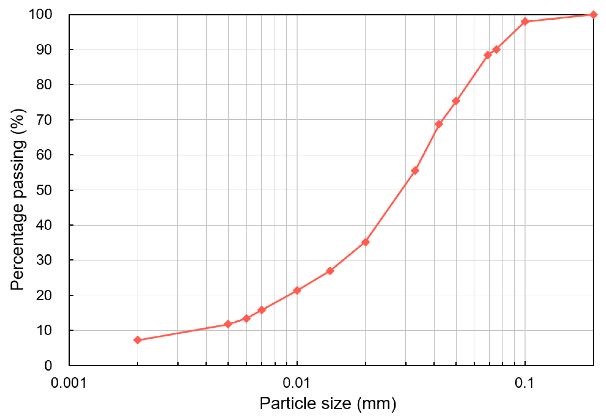
2.1.1. Loess
2.1.2. BF and PVAC
2.1.3. Urease and EICP Solution
2.2. Slope Sample Preparation and Treatment
2.3. Surface Strength, Crust Layer Thickness, and CaCO3 Content Determination
2.4. Scanning Electron Microscopy Test
2.5. Rainfall Simulation Test
2.6. Dry–Wet Cycle Test
3. Results and Discussion
3.1. Surface Strength, Crust Layer Thickness, and CaCO3 Content Determination
3.2. Microscopic Characteristics
3.3. Rainfall Simulation Test
3.3.1. 3D Scanner Observation
3.3.2. Quantification of Surface Erosion
3.4. Dry–Wet Cycle Test
3.4.1. Visual Observation
3.4.2. Quantification of Surface Erosion
4. Conclusions
- The EICP, EICP-BF, and EICP-PVAC treatments improved surface strength (SS) of loess slope. The SS increased with increasing the content of basalt fiber (BF) or the concentration of polyvinyl acetate emulsion (PVAC), which was attributed to the more stable spatial structure of CaCO3 precipitation caused by additional BF or PVAC. However, the thickness of crust layer decreased with increasing the BF content or PVAC concentration because the crust layer prevented the further infiltration of solution. The CaCO3 content increased progressively with the increasing number of EICP treatment cycles;
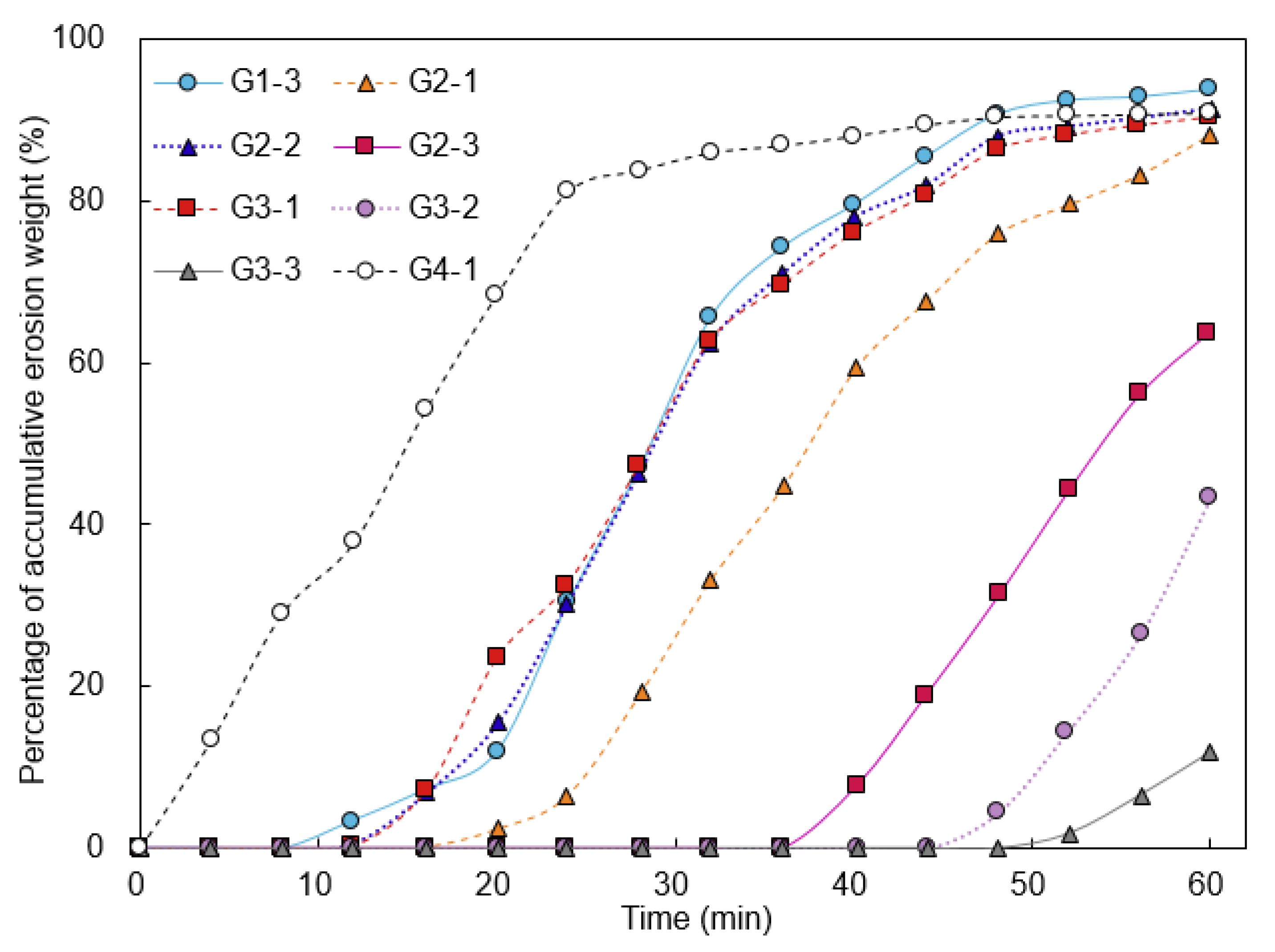
- Under the rainfall conditions, the time until erosion was delayed and the stability was improved for loess slope samples treated with EICP, EICP-BF, and EICP-PVAC. The percentage of accumulative erosion weight of the distilled water treated sample was increased rapidly to 81% within the first 24 min, whereas it remained at 0% for samples treated with EICP-0.5% BF, EICP-30 g/L PVAC, or EICP-50 g/L PVAC. The high content of BF and PVAC achieved superior erosion control on loess slopes during rainfall.
- The addition of BF effectively inhibited the development of surface cracks in loess slope samples, especially at a BF content of 0.5%. With the increasing number of dry–wet cycles, the accumulative loess loss weight of samples treated with various methods increased gradually. The loess loss in EICP-30 g/L PVAC treated slopes subjected 6 dry–wet cycles remained smaller than 5.5%. In addition, loess loss weight percentage reached 13.2% for the sample treated with EICP-50 g/L PVAC as the surface loess was destroyed by pieces.
Supplementary Materials
Author Contributions
Funding
Institutional Review Board Statement
Informed Consent Statement
Data Availability Statement
Conflicts of Interest
References
- Juang, C.H.; Dijkstra, T.; Wasowski, J.; Meng, X.M. Loess geohazards research in China: Advances and challenges for mega engineering projects. Eng. Geol. 2019, 251, 1–10. [Google Scholar] [CrossRef]
- Sun, X.H.; Miao, L.C.; Chen, R.F.; Wang, H.X.; Xia, J.X. Surface rainfall erosion resistance and freeze-thaw durability of bio-cemented and polymer-modified loess slopes. J. Environ. Manag. 2022, 301, 113883. [Google Scholar] [CrossRef] [PubMed]
- Wei, W.; Chen, L.D.; Fu, B.J.; Huang, Z.L.; Wu, D.P.; Gui, L.D. The effect of land uses and rainfall regimes on runoff and soil erosion in the semi-arid loess hilly area, China. J. Hydrol. 2007, 335, 247–258. [Google Scholar] [CrossRef]
- Chen, H.; Zhang, X.P.; Ablaa, M.; Lü, D.; Yan, R.; Ren, Q.F.; Ren, Z.Y.; Yang, Y.H.; Zhao, W.H.; Lin, P.F.; et al. Effects of vegetation and rainfall types on surface runoff and soil erosion on steep slopes on the Loess Plateau, China. Catena 2018, 170, 141–149. [Google Scholar] [CrossRef]
- Xin, W.; Lin, Z. Soil erosion control practices in the Chinese Loess Plateau: A systematic review. Environ. Dev. 2020, 34, 100493. [Google Scholar]
- Wang, J.-J.; Liang, Y.; Zhang, H.-P.; Wu, Y.; Lin, X. A loess landslide induced by excavation and rainfall. Landslides 2014, 11, 141–152. [Google Scholar] [CrossRef]
- Zhuang, J.Q.; Peng, J.B.; Wang, G.H.; Javed, I.; Wang, Y.; Li, W. Distribution and characteristics of landslide in Loess Plateau: A case study in Shaanxi province. Eng. Geol. 2018, 236, 89–96. [Google Scholar] [CrossRef]
- Cui, Y.; Kong, J.M.; Ni, Z.Q. Key dominant mechanism of heavy rain in landslide development and analysis of a typical case. J. Catastrophol. 2011, 26, 13–17. [Google Scholar]
- Zhang, Z. Field Test of Rainfall Infiltration of Loess Slopes and Its Disaster Warning in Northern Shanxi Province. Master’s Thesis, Xi’an University of Technology, Xi’an, China, 2018. [Google Scholar]
- Wu, J.-J.; Cheng, Q.-G.; Liang, X.; Cao, J.-L. Stability analysis of a high loess slope reinforced by the combination system of soil nails and stabilization piles. Front. Struct. Civ. Eng. 2014, 8, 252–259. [Google Scholar] [CrossRef]
- Zhao, Z.F.; Zhu, Y.P.; Ye, S.H. Calculation of horizontal displacement of loess fill slope supported by frame prestressed anchors based on minimum potential energy method. Sci. Rep. 2022, 12, 11281. [Google Scholar] [CrossRef]
- Wang, Y.D.; Liu, X.F.; Li, J.; Wang, Y.D.; Bai, J.Z.; Zhou, Z.X. Quantifying the spatial flow of soil conservation service to optimize land-use pattern under ecological protection scenarios. Front. Earth Sci. 2022, 10, 957520. [Google Scholar] [CrossRef]
- Neupane, D.; Yasuhara, H.; Kinoshita, N.; Unno, T. Applicability of Enzymatic Calcium Carbonate Precipitation as a Soil-Strengthening Technique. J. Geotech. Geoenviron. Eng. 2013, 139, 2201–2211. [Google Scholar] [CrossRef]
- Wu, C.Z.; Chu, J.; Wu, S.F.; Hong, Y. 3D characterization of microbially induced carbonate precipitation in rock fracture and the resulted permeability reduction. Eng. Geol. 2019, 249, 23–30. [Google Scholar] [CrossRef]
- Kavazanjian, E.; Hamdan, N. Enzyme Induced Carbonate Precipitation (EICP) Columns for Ground Improvement. In Proceedings of the International Foundations Congress and Equipment Expo 2015, San Antonio, TX, USA, 17–21 March 2015; pp. 2252–2261. [Google Scholar] [CrossRef]
- Ahenkorah, I.; Rahman, M.; Karim, R.; Beecham, S.; Saint, C. A Review of Enzyme Induced Carbonate Precipitation (EICP): The Role of Enzyme Kinetics. Sustain. Chem. 2021, 2, 92–114. [Google Scholar] [CrossRef]
- Dilrukshi, R.; Nakashima, K.; Kawasaki, S. Soil improvement using plant-derived urease-induced calcium carbonate precipitation. Soils Found. 2018, 58, 894–910. [Google Scholar] [CrossRef]
- Wu, M.; Hu, X.; Zhang, Q.; Zhao, Y.; Cheng, W.; Xue, D. Preparation and performance of a biological dust suppressant based on the synergistic effect of enzyme-induced carbonate precipitation and surfactant. Environ. Sci. Pollut. Res. 2022, 29, 8423–8437. [Google Scholar] [CrossRef] [PubMed]
- Hamdan, N.; Zhao, Z.; Mujica, M.; Kavazanjian, E.; He, X. Hydrogel-Assisted Enzyme-Induced Carbonate Mineral Precipitation. J. Mater. Civ. Eng. 2016, 28, 04016089. [Google Scholar] [CrossRef]
- Almajed, A.; Abbas, H.; Arab, M.; Alsabhan, A.; Hamid, W.; Al-Salloum, Y. Enzyme-Induced Carbonate Precipitation (EICP)-Based methods for ecofriendly stabilization of different types of natural sands. J. Clean. Prod. 2020, 274, 122627. [Google Scholar] [CrossRef]
- Sun, X.; Miao, L.; Wang, H.; Yin, W.; Wu, L. Mineralization crust field experiment for desert sand solidification based on enzymatic calcification. J. Environ. Manag. 2021, 287, 112315. [Google Scholar] [CrossRef]
- Bang, S.S.; Bang, S.; Frutiger, S.; Nehl, L.M.; Comes, B.L. Application of Novel Biological Technique in Dust Suppression. In Proceedings of the Transportation Research Board 88th Annual Meeting Transportation Research Board, Washington, DC, USA, 11–15 January 2009. [Google Scholar]
- Zhao, Z.; Hamdan, N.; Shen, L.; Nan, H.; Almajed, A.; Kavazanjian, E.; He, X. Biomimetic hydrogel composites for soil stabilization and contaminant mitigation. Environ. Sci. Technol. 2016, 50, 12401–12410. [Google Scholar] [CrossRef]
- Almajed, A.; Tirkolaei, H.K.; Kavazanjian, E.; Hamdan, N. Enzyme Induced Biocementated Sand with High Strength at Low Carbonate Content. Sci. Rep. 2019, 9, 1135. [Google Scholar] [CrossRef]
- Cui, M.J.; Lai, H.J.; Hoang, T.; Chu, J. One-phase-low-pH enzyme induced carbonate precipitation (EICP) method for soil improvement. Acta Geotech. 2020, 16, 481–489. [Google Scholar] [CrossRef]
- Bu, F.; Liu, J.; Bai, Y.; Prasanna Kanungo, D.; Song, Z.; Kong, F.; Pan, C. Effects of the Preparation Conditions and Reinforcement Mechanism of Polyvinyl Acetate Soil Stabilizer. Polymers 2019, 11, 506. [Google Scholar] [CrossRef] [Green Version]
- Zhao, Y.; Xiao, Z.; Fan, C.; Shen, W.; Wang, Q.; Liu, P. Comparative mechanical behaviors of four fiber-reinforced sand cemented by microbially induced carbonate precipitation. Bull. Eng. Geol. Environ. 2020, 79, 3075–3086. [Google Scholar] [CrossRef]
- Militký, J.; Mishra, R.; Jamshaid, H. Basalt fibers. In Handbook of Properties of Textile and Technical Fibres; Woodhead Publishing: Cambridge, UK, 2018; pp. 805–840. [Google Scholar]
- Khan, M.; Cao, M.; Chu, S.; Ali, M. Properties of hybrid steel-basalt fiber reinforced concrete exposed to different surrounding conditions. Constr. Build. Mater. 2022, 322, 126340. [Google Scholar] [CrossRef]
- Zhang, Y.; Pang, B.; Yang, S.; Fang, W.; Yang, S.; Yuan, T.-Q.; Sun, R.-C. Improvement in Wood Bonding Strength of Poly (Vinyl Acetate-Butyl Acrylate) Emulsion by Controlling the Amount of Redox Initiator. Materials 2018, 11, 89. [Google Scholar] [CrossRef] [Green Version]
- Chu, J.; Ivanov, V.; Stabnikov, V.; Li, B. Microbial method for construction of an aquaculture pond in sand. Géotechnique 2013, 63, 871–875. [Google Scholar] [CrossRef]
- Jiang, N.J.; Soga, K.; Kuo, M. Microbially induced carbonate precipitation for seepage-induced internal erosion control in sand-clay mixtures. J. Geotech. Geoenviron. Eng. 2017, 143, 04016100. [Google Scholar] [CrossRef]
- Gao, Y.; He, J.; Tang, X.; Chu, J. Calcium carbonate precipitation catalyzed by soybean urease as an improvement method for fine-grained soil. Soils Found. 2019, 59, 1631–1637. [Google Scholar] [CrossRef]
- Zhang, F.; Kong, R.; Peng, J. Effects of heating on compositional, structural, and physicochemical properties of loess under laboratory conditions. Appl. Clay Sci. 2018, 152, 259–266. [Google Scholar] [CrossRef]
- Alavinia, M.; Saleh, F.N.; Asadi, H. Effects of rainfall patterns on runoff and rainfall-induced erosion. Int. J. Sediment Res. 2019, 34, 270–278. [Google Scholar] [CrossRef]
- Zhang, Q.; Wang, Z.; Wu, B.; Shen, N.; Liu, J. Identifying sediment transport capacity of raindrop-impacted overland flow within transport-limited system of interrill erosion processes on steep loess hillslopes of China. Soil Tillage Res. 2018, 184, 109–117. [Google Scholar] [CrossRef]
- Tang, C.-S.; Cui, Y.-J.; Shi, B.; Tang, A.-M.; Liu, C. Desiccation and cracking behaviour of clay layer from slurry state under wetting–drying cycles. Geoderma 2011, 166, 111–118. [Google Scholar] [CrossRef] [Green Version]
- Tang, C.S.; Wang, D.Y.; Shi, B.; Li, J. Efect of wetting-drying cycles on profle mechanical behavior of soils with different initial conditions. Catena 2016, 139, 105–116. [Google Scholar] [CrossRef]
- Wu, C.Z.; Chu, J. Biogrouting method for stronger bond strength for aggregates. J. Geotech Geoenviron. 2020, 146, 06020021. [Google Scholar] [CrossRef]
- Jiang, H.; Cai, Y.; Liu, J. Engineering Properties of Soils Reinforced by Short Discrete Polypropylene Fiber. J. Mater. Civ. Eng. 2010, 22, 1315–1322. [Google Scholar] [CrossRef]
- Wu, C.Z.; Chu, J.; Cheng, L.; Wu, S.F. Biogrouting of Aggregates Using Premixed Injection Method with or without pH Adjustment. J. Mater. Civ. Eng. 2019, 31, 06019008. [Google Scholar] [CrossRef]
- Jazi, M.A.; Ramezani, S.A.A.; Haddadi, S.A.; Ghaderi, S.; Azamian, F. In situ emulsion polymerization and characterization of PVAc nanocomposites including colloidal silica nanoparticles for wood specimens bonding. J. Appl. Polym. Sci. 2020, 137, 48570. [Google Scholar] [CrossRef]
- Omoregie, A.I.; Palombo, E.A.; Ong, D.E.; Nissom, P.M. A feasible scale-up production of Sporosarcina pasteurii using custom-built stirred tank reactor for in-situ soil biocementation. Biocatal. Agric. Biotechnol. 2020, 24, 101544. [Google Scholar] [CrossRef]
- Sun, X.H.; Miao, L.C.; Wang, H.X.; Chen, R.F.; Wu, L.Y. Bio-cementation for the mitigation of surface erosion in loess slopes based on simulation experiment. J. Soils Sediments 2022, 22, 1804–1818. [Google Scholar] [CrossRef]


| Sample No. | Treatment | Treatment Cycles | SS (kPa) | Thickness (mm) |
|---|---|---|---|---|
| G1-1 | EICP | 1 | 1.469 | 5.83 |
| G1-2 | 2 | 1.640 | 6.22 | |
| G1-3 | 3 | 1.742 | 6.98 | |
| G2-1 | EICP-0.1% BF | 3 | 2.004 | 5.54 |
| G2-2 | EICP-0.3% BF | 3 | 2.269 | 5.34 |
| G2-3 | EICP-0.5% BF | 3 | 2.221 | 5.07 |
| G3-1 | EICP-10 g/L PVAC | 3 | 1.932 | 5.87 |
| G3-2 | EICP-30 g/L PVAC | 3 | 2.238 | 5.53 |
| G3-3 | EICP-50 g/L PVAC | 3 | 2.317 | 4.80 |
| G4-1 | Distilled water | 3 | 1.247 | / |
Disclaimer/Publisher’s Note: The statements, opinions and data contained in all publications are solely those of the individual author(s) and contributor(s) and not of MDPI and/or the editor(s). MDPI and/or the editor(s) disclaim responsibility for any injury to people or property resulting from any ideas, methods, instructions or products referred to in the content. |
© 2023 by the authors. Licensee MDPI, Basel, Switzerland. This article is an open access article distributed under the terms and conditions of the Creative Commons Attribution (CC BY) license (https://creativecommons.org/licenses/by/4.0/).
Share and Cite
Shen, D.; Liu, Z.; Song, Z.; Wu, C. Reinforcement Mechanism and Erosion Resistance of Loess Slope Using Enzyme Induced Calcite Precipitation Technique. Sustainability 2023, 15, 1044. https://doi.org/10.3390/su15021044
Shen D, Liu Z, Song Z, Wu C. Reinforcement Mechanism and Erosion Resistance of Loess Slope Using Enzyme Induced Calcite Precipitation Technique. Sustainability. 2023; 15(2):1044. https://doi.org/10.3390/su15021044
Chicago/Turabian StyleShen, Danyi, Zhenyuan Liu, Zhichao Song, and Chuangzhou Wu. 2023. "Reinforcement Mechanism and Erosion Resistance of Loess Slope Using Enzyme Induced Calcite Precipitation Technique" Sustainability 15, no. 2: 1044. https://doi.org/10.3390/su15021044