Article

A Comprehensive Study of the Effects of Various Operating Parameters on a Biogas-Diesel Dual Fuel Engine

by
M. Feroskhan
1,*,
Saleel Ismail
2,
Gobinath Natarajan
1,
Sreekanth Manavalla
1,3,
T. M. Yunus Khan
4,
Shaik Dawood Abdul Khadar
5 and
Mohammed Azam Ali
4
1
School of Mechanical Engineering, Vellore Institute of Technology (VIT) Chennai, Chennai 600127, Tamilnadu, India
2
Department of Mechanical Engineering, National Institute of Technology Calicut, Kozhikode 673601, Kerala, India
3
Electric Vehicle Incubation Testing and Research Center, Vellore Institute of Technology (VIT) Chennai, Chennai 600127, Tamilnadu, India
4
Department of Mechanical Engineering, College of Engineering, King Khalid University, Abha 61421, Saudi Arabia
5
Department of Industrial Engineering, College of Engineering, King Khalid University, Abha 61421, Saudi Arabia
*
Author to whom correspondence should be addressed.
Sustainability 2023, 15(2), 1232; https://doi.org/10.3390/su15021232
Submission received: 5 December 2022 / Revised: 31 December 2022 / Accepted: 4 January 2023 / Published: 9 January 2023

Abstract

:
Alternative fuels are found to be the most promising solution to the problem of conventional IC engine pollution because their use curtails its huge emissions without exerting a negative impact on its performance. In this research, a conventional compression ignition engine is investigated by operating it with the combination of simulated biogas and neat diesel under a dual fuel mode of operations. The simulated biogas in the current work comprises different proportions of methane and carbon dioxide in the mixture. The full factorial approach in this work involved studying the effects of parameters such as biogas flow rate, composition, intake temperature, torque, and methane enrichment (complete removal of CO2 from biogas) on the engine performance, emissions, and combustion indices with an extensive number of experiments. It is witnessed from the research that biogas is capable of providing a maximum of 90% of the overall energy input, while the CI engine operates under dual fuel mode. Under the dual fuel mode of operation involving biogas, a significant amount of reductions are witnessed in secondary fuel consumption (67%), smoke (75%), and NOx (55%) emissions. At low flow rates, biogas is found to improve brake thermal efficiency (BTE), whereas it reduces hydrocarbon and carbon monoxide emissions. Methane enrichment resulted in more diesel substitution by 5.5% and diminishes CO and HC emissions by 5% and 16%, respectively. Increasing the intake temperature caused an increase in thermal efficiency (2%) and a reduction in diesel consumption (~35%), and it curtailed all emission elements except NOx.

1. Introduction

The major energy resources such as coal, petroleum, and natural gas are not renewable. Their demand, prices, depletion, and environmental concerns have increased the search for alternative fuels. Among many alternative fuels biogas can be considered a promising fuel due to its renewable nature [1]. Biogas, when used as a fuel, benefits in multiple ways as follows; Acts as a renewable source of energy, It paves an easy way for disposing of biological waste, and it helps with the easy handling of methane which is considered to be an influential greenhouse gas. Biogas possesses several benefits such as transportability in cylinders [2], residue-free combustion, carbon dioxide (CO2) neutrality [3], and low production cost [4]. Based on the biomass feedstock, the concentrations of the major constituents of biogas (viz., CH4, CO2, H2S, etc.) vary from sample to sample [3]. Typically, CO2 content (by volume) in biogas ranges from 25 to 40% [5]. The properties of representative samples of biogas are discussed in the literature [6,7,8,9]. The presence of CO2 in biogas reduces the flammability range, energy density, heating value, and flame velocity compared to methane. Biogas shows good knocking resistance in spark ignition (SI) engines, which is primarily due to its high self-ignition property. However, igniting it in compression ignition (CI) engines is difficult [10]. Removal of CO2 from biogas is one of the possible means of overcoming the drawbacks discussed above [11]. This removal (purification) process is referred to as methane enrichment. The biogas-diesel dual fuel mode was investigated by many researchers by taking different parameters into concern such as flow rate (biogas) [12], methane concentration [13,14], CO2 fraction [15], O2 fraction [8], engine speed [16], biogas energy ratio [17], compression ratio [9], and EGR flow rate [18]. Diesel-biodiesel blends were used instead of diesel by a few researchers. The dual fuel mode shows high efficiency at high loads and reduces conventional fuel intake [19]. Soybean methyl ester [20], pongamia pinaata biodiesel [15], palm oil methyl ester [21], and rice bran methyl esters [22] have been studied. The effects of various biogas feedstock such as azolla, corn husk [23], tamarind seed, and rice bran (TSRB) [24] etc. have been compared. A comprehensive review of various aspects of biogas fueled dual fuel engines is presented in Section 2.

2. CI Engines Involving Biogas

CI engines offer higher BTE and reduced hydrocarbon emissions over SI engines. Biogas can be employed in such CI engines either in dual fuel or in Homogeneous Charge Compression Ignition (HCCI) modes. In the former, biogas is inducted with air through the intake manifold, and pilot fuel (diesel) is typically injected into the cylinder late in the compression stroke. The pilot fuel auto-ignites first and this flame subsequently consumes the surrounding biogas-air mixture. Dual fuel mode is employed in the present study. The operations of the CI engine in (i) duel fuel mode with the inclusion of biogas and (ii) neat-diesel mode are compared in performance, emission, and combustion aspects, and the results are presented in this section.

2.1. Performance Indices

Bora et al. [9] and Yoon and Lee [25] have reported that the thermal efficiency was decreased due to low flame speed, its combustion temperature, and the higher compression (pumping) work required because of the CO2 content in biogas [15,21]. Up to 48% diesel substitution was achieved by Duc and Wattanavichien [16] in an indirect injection engine with biogas in dual fuel mode. As for fuel, conversion is considered. Both the diesel and dual fuel modes exhibit the same efficiencies at full loads; however, diesel mode is found to provide higher BTE even at part loads. An increase in compression ratio, intake temperature, and oxygen content can increase the brake thermal efficiency [8,9,26]. Simulated biogas, which is a mixture of methane and CO2, is found utilized for many experimental studies under dual fuel mode [15,27,28]. It is witnessed from the literature that the BSEC (Brake Specific Energy Consumption) of a CI engine is reasonably comparable in range among the normal mode and biogas-diesel dual fuel mode [29].
Sorathia and Yadav [30] witnessed no reduction in the thermal efficiency of CI engines operated with diesel-biogas dual fuel mode. Energy loss is found to be predominant in cooling than in exhaust under dual fuel mode of operations. Exergy efficiency was observed to be incremented, and, according to authors, the Exergy destroyed diminished in dual fuel mode. Investigation with variant CH4:CO2 ratios indicated that a higher BTE can be obtained at the ratio of 7:3 [13]. This outcome is justified by attributing the dissociating phenomenon of CO2 at elevated temperatures to CO and O2. CO is capable of burning swiftly, and henceforth it promotes the burning rates. The limited concentration of CO2 in biogas (20–30%, for example) could minimize the BSFC and any further rise in its concentration would adversely increase fuel consumption, mainly due to the rise of inert gas in the composition [31]. Luijten and Kerkhof [32], based on their experimental studies, witnessed the restriction of the biogas percentage as a substitution for diesel. Based on the energy release aspect, 70% of methane-containing biogas can be used to replace diesel usage by 55%. However, the authors claimed that biogas usage is limited to having a maximum of 40% of methane in it, which can contribute to a replacement of 35% of diesel.
Split injection, exhaust gas recirculation (EGR), and hydrogen addition are observed as the key methods for improving thermal efficiency under the dual fuel mode of operation [33]. Barik and Murugan [7] investigated the dual-fuel engine’s performance by varying the flow rates of pilot fuel and the biogas. At full load, the diesel substitution was reported to be 30%. The volumetric efficiency was found to be declined, and the BSEC rose to high values; this result could be due to the effect that more CO2 displaces much of the air and diminishes the burning rate. The authors reported that increasing the flow rate of biogas could result in the reduction of both the volumetric and brake thermal efficiencies. Rahman and Ramesh [34] have studied the effect of methane fraction in the range of 24 to 68%. However, the effect of methane fraction in the complete range, from pure biogas (0% methane) to pure methane, is found to be concentrated much.

2.2. Emission Indices

Greater amounts of CO2 present in biogas resulted in lower combustion temperatures, which could adversely increase the emissions such as CO and HC, while NOx and particulate matter are lower in comparison with basic CI mode [17]. Barik and Sivalingam [35] observed a drop in exhaust temperature by 2.8%, an increase of 16% in CO and 21% in HC emissions, and a decrease in NOx and soot by 35% and 41.3%, respectively, in comparison with the neat-diesel operation for the maximum diesel substitution under full-load conditions. Higher CO2 fractions resulted in high inertness, thereby acting as a non-participating gas and thereby decreasing the thermal efficiency. HC and CO reduced when the compression ratio was brought up due to a rise in the in-cylinder temperatures, but repercussions followed as NOx and CO2 surged [9]. The parameters can be controlled by managing the injection quantity of the pilot fuel [29,36]. Barik and Murugan [7] deduced that the 0.9 kg/h biogas flow rate was better from the performance and emission indices viewpoint. This works out to replace 0.215 kg/h of conventional diesel. Higher oxygen content reduces the released methane and CO emissions, which showed an erratic undefined trend. While minimizing the instabilities during combustion, it was also found that biogas becomes a promising substitution for diesel due to its oxygen enrichment. [8].
Exhaust gas recirculation led to a decline in lean operating conditions and combustion efficiency, while NOx emissions too dropped NOx formation is due to high combustion temperatures under rich mixture conditions and spray of pilot fuel for lean mixtures [37].

2.3. Combustion Indices

In contrast with ignition by spark, diesel pilot fuel injection proves to be more effective, thus providing suitable ignition energy to the inducted fuel mixture. Longer Ignition delay (ID) is observed for the dual fuel mode compared to CI mode due to higher concentrations of CO2 [37]. Reduction in combustion duration and low exhaust temperatures are observed in an indirect injection engine under dual fuel mode with biogas replacing diesel up to 48% [16]. In an experiment with dual fuel (biogas-diesel) engine, the maximum net heat release (NHRR) increased by 30% in comparison with normal diesel-only mode on the same loads and engine speed [29]. An increment in ID can be counterbalanced by inducting larger pilot fuel. For the combustion of 100% methane, the ignition delay is not related to the pilot fuel injection quantity [36]. Bora et al. [9] stated in the inference that the concentration of pilot fuel supplied can be substantially reduced by an operating engine on higher compression ratios, which abbreviates the ID of biogas at raised temperatures. Compression ratios from 16 to 18 were tested and ID was also reduced by opting for more oxygen enrichment. This proves to be useful as it raises reaction rates and flame propagation speed as well. Incrementing oxygen content in the air by 6% resulted in reduced ignition delay by 3 °CA [8]. Ignition delay was also reported to be lower for a dual-fuel engine coated with thermal barriers over the bare dual-fuel engine [38]. Higher Methane concentration in biogas led to higher in-cylinder pressures and a longer combustion duration whilst reducing ID [14]. Bora et al. [9] noticed a decrement in peak cylinder pressure for biogas-dual fuel mode ad Higher MHRR and ID compared to operation on pure diesel. Ray et al. [39] reported that the ignition delay of pilot fuel has a direct relation to the ratio of biogas to diesel. Notably, 10–20% of the amount of pilot fuel injected proved abundant for dual fuel operations. The authors concluded that an engine incorporated with a governor is sufficient to control the output. Diesel substitution is generally lower in such instances. Park and Yoon [40] justified that the increment in port injection ratio (energy input from biogas/total energy input) in diesel-biogas mode led to more delayed ignition lag in comparison with the diesel-gasoline mode.

2.4. Motivation for the Present Study

Biogas is a promising engine fuel by virtue of its renewability, carbon neutrality, effectiveness in bio-waste management, potential of harnessing methane emission, etc. Biogas-diesel dual-fuel engines can be versatile mechanisms to cater to a variety of energy requirements, lending self-sufficiency to communities and simultaneously ensuring efficient waste management and environmental protection. In spite of a wealth of studies on such engines, the review of literature presented in Section 2 reveals a lack of sufficient research on some important factors, such as the following factors:
  • Methane fraction of biogas spanning the full range (from raw biogas to pure methane).
  • Intake charge temperature.
Understanding the effect of biogas composition on engine output is vital because it helps in selecting the appropriate feedstock and purification method, thus affecting the plant design, operating cost, etc. Waste heat recovery techniques offer a ready means of intake heating, which controls biogas combustion and in turn influences engine performance and emissions. The quantity of exhaust thermal energy to be recovered, the design of the charge preheater, etc. can be guided by knowing the impact of intake heating on engine output.
In light of the benefits and challenges of biogas, the present work is an attempt to investigate the effects of four input variables (biogas flow rate, composition, methane enrichment, and intake temperature) on all three descriptors of engine output, viz., combustion, performance, and emissions. A set of data comprising the results of 320 experimental trials is taken for a full factorial study, which encompasses all load ranges, as mentioned in Section 5 of this manuscript. Such a comprehensive study has not been attempted earlier to the best of the authors’ knowledge, and the results are expected to be promising to choose the most effective way of utilizing biogas in dual fuel mode.

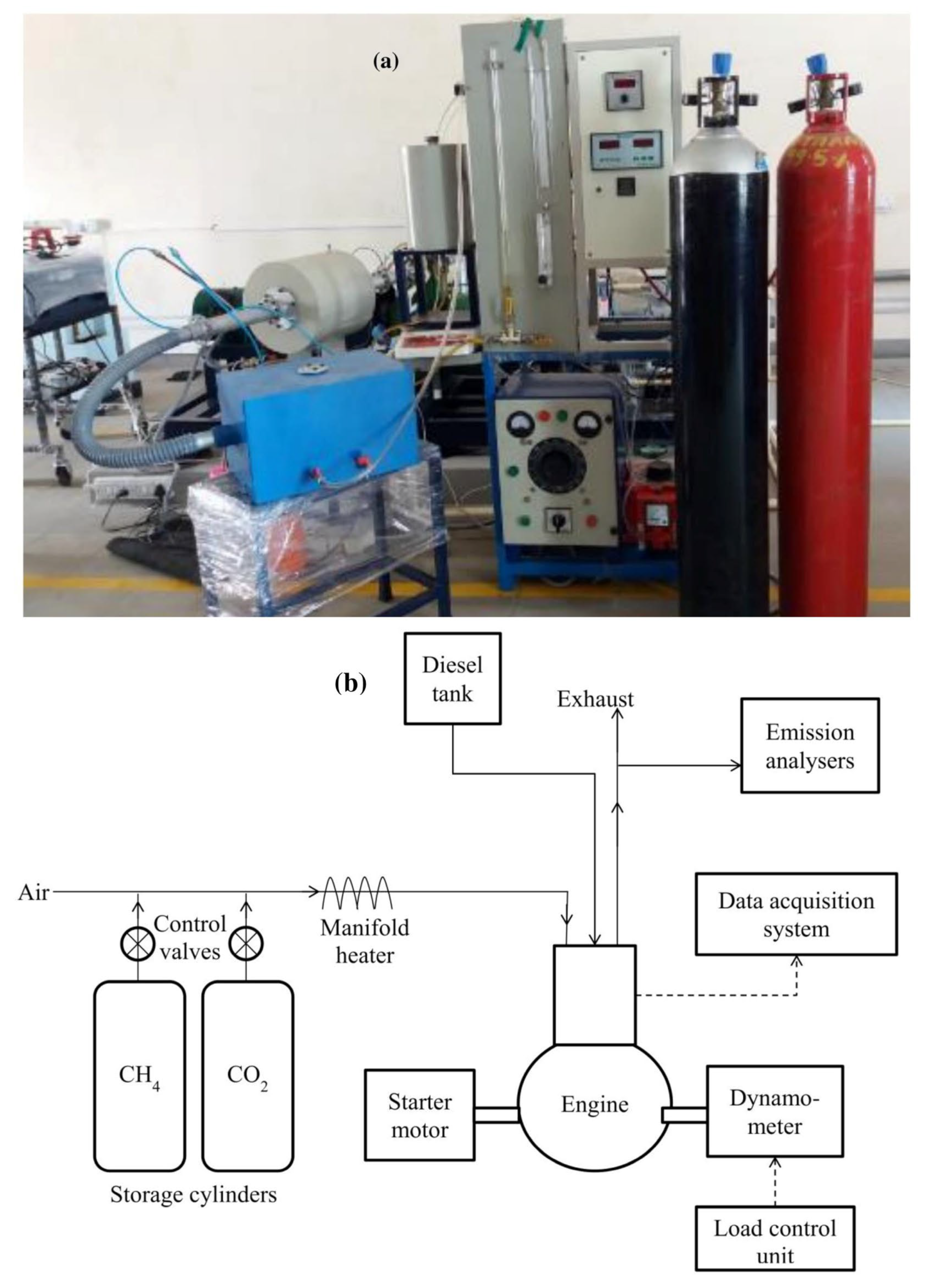
3. Experimental Setup

A standard single-cylinder four-stroke direct injection CI engine of a water-cooled type was used in this experiment. The relevant engine specifications are provided in Table 1. The testing setup was employed with the usage of a biogas induction system to execute the experiment in dual fuel mode. Figure 1 illustrates the experimental setup schematic. Biogas was synthesized by blending compressed CH4 (99.5%) and CO2 (99.9%) supplied from separate cylinders provisioned with pressure-regulating devices to perpetuate the delivery pressure. The simulated biogas composition is varied in the experiments by varying the flow rates of the individual gases separately. Biogas purity was illustrated by methane concentration (by vol.) in it. Reduction in CO2 flow rate aided in reproducing the effect of biogas purification (Methane enrichment). Thermal mass flow meters were employed to measure the gas flow rates. A Y-shaped nozzle was employed in the manifold, where CH4 and CO2 were mixed in a cylindrical chamber. The location of the nozzle was at the cylinder upstream to minimize the flow oscillation, which is induced primarily due to the motion of the piston and valve, thus assuring steady reading values in the flowmeters. Further downstream, a honeycomb structured heater was installed in the intake manifold to preheat the biogas–air mixture. The rate of heating was controlled using a voltage regulator. With the aid of an orifice meter which was in connection to a differential manometer, the airflow rate was measured, and a buret and a stopwatch were used to determine the diesel flow rate. K-type thermocouples were fixed in the setup to measure temperatures at the intake charge, entry, and exit of the engine coolant.
In-cylinder pressure values were recorded with the use of a piezoelectric transducer, which was mounted on the cylinder head. The electric signal generated was amplified and using a charge amplifier, it is then converted into a voltage signal. A crank angle encoder of electromagnetic type was connected with the shaft of the engine. Both the charge amplifier and the angle encoder signals were transcribed by means of the data acquisition method, and their results were processed in the Lab View-based software program. Furthermore, the program helps in obtaining the history of pressure data for each crank angle. An eddy current dynamometer controlled through a separate unit was utilized to vary the engine load. Exhaust gas emissions CO, NOx, and HC were computed with a portable gas analyzer while a smoke meter (opacity-based) was employed to determine smoke and particulate matter values.

4. Uncertainty Analysis

The instrumentation details used for the present study are provided in Table 2, while the uncertainties associated with the output parameters are estimated, as explained by Moffat [41] and are listed in Table 3.

5. Experimental Methodology

The full factorial study which was carried out in the present research work aimed to investigate the effects of biogas flow rate, methane fraction, methane enrichment, torque, and intake charge temperature on performance as well as emission and combustion characteristics under dual fuel operations (biogas-diesel). The ranges for input parameters were selected considering the complete operating range of the engine. The range of biogas flow rate (from 2 to 16 Ls per minute) corresponds to the fraction of 10% to 90% of the overall energy output obtained during combustion. The levels of methane fraction (viz., 50 to 100%) represent the methane availability in naturally produced biogas and pure methane, respectively. The intake temperature was made to vary from room conditions (35 °C) to the maximum operating limit of the heater (100 °C) in order to study the effects of charge preheating (manifold heating). Notably, 20 to 90 percent of the engine loads are used at the constant engine rpm of 1900. The input parameters for the present research work that are used for a total of 320 experimental trials are provided in Table 4. The present study considered the following output parameters; Secondary Fuel Energy Ratio (SFER), diesel consumption, BTE, air-fuel ratio, overall equivalence ratio, HC, CO, NOx and smoke emissions, maximum cylinder pressure, location of maximum cylinder pressure, ID, and maximum heat release rate. Additional experiments were conducted to investigate the effect of methane enrichment in dual fuel mode with biogas (CH4 + CO2) flow rates of 10 + 10 L/min and 10 + 0 L/min (pure methane).

6. Engine Independent Parameters

Studying the variation of engine output in terms of engine independent parameters helps in assessing the applicability of results and comparing them across different engines. Applied torque is varied from 5 Nm and 20 Nm. This corresponds to a BMEP range of 1.31 bar to 5.23 bar. The list of engine torque values studied, along with the corresponding percentage of full load and BMEP values, is presented in Table 5.

7. Formulae Used

7.1. Performance Indices

The formulae used for calculating the performance indices are given below:
Brake thermal efficiency,
ɳ b t = P b   E ˙ t o t a l
where   E ˙ t o t a l is total energy supplied by the fuel (biogas + diesel) and Pb is brake power
The total fuel energy is expressed as
  E ˙ t o t a l =   E ˙ d i e s e l +   E ˙ b i o g a s
where the energy released from each fuel is expressed as
  E ˙ = m ˙ × L C V  
where m ˙ is the fuel mass flow rate and LCV is the lower calorific value of the fuel (LCV for diesel and methane are 40,928 kJ/kg and 50,000 kJ/kg, respectively)
Secondary Fuel Energy Ratio (SFER),
S F E R =   E ˙ d i e s e l   E ˙ t o t a l  
Air-fuel ratio,
A F R =   m ˙ a i r   m ˙ f u e l
where   m ˙ f u e l represents the total mass flow rate of biogas and diesel.
Equivalence ratio,
E R = A F R s t o i c h   A F R
where A F R s t o i c h is the stoichiometric air-fuel ratio.
A F R s t o i c h =   m ˙ b i o g a s   m ˙ f u e l * A F R s t o i c h b i o g a s +   m ˙ d i e s e l   m ˙ f u e l * A F R s t o i c h d i e s e l
A F R s t o i c h d i e s e l = 14.5 A F R s t o i c h b i o g a s = M O 2 M C H 4 +   V ˙ C O 2   V ˙ C H 4 * M C O 2 * 0.232
where V   ˙ is volume flow rate and M is molecular weight.

7.2. Emission Indices

The gas emission analyzer indicated emission levels on a volumetric basis—NOx and HC concentrations were displayed in ppm, while that of CO was in percentage by volume. To facilitate comparison across different operating modes and load conditions, the concentrations of the emissions (denoted by index i) were expressed in g/kWh using the following equation [42]:
E m , i =   E v , i × M i M e x h ×   m ˙ e x h P b × C F
where Em,i and Ev,i are the emission concentrations on mass (g/kWh) and volume (ppm or % volume) basis, respectively. Mi and Mexh are the molecular mass of the emission species i and that of the exhaust gas (in g/mol),   m ˙ e x h is the exhaust mass flow rate (g/h), and CF is a conversion factor to obtain mole fraction (10−6 for ppm and 10−2 for % vol).

7.3. Combustion Indices

A LabVIEW-based software program was used to obtain pressure data averaged over 100 consecutive engine operating cycles. From the pressure history, maximum pressure and location of maximum pressure were determined and compared across the operating modes in order to obtain insight into the combustion process.
The pressure data was further used to calculate the heat release rate and ID. The net heat release rate was defined as [9]
d Q d θ = γ γ 1 × p × d V d θ + 1 γ 1 × V × d p d θ
where p is the instantaneous cylinder pressure and V is the volume at the crank angle θ . γ is the ratio of specific heat temperatures.
ID was defined as the crank angle duration from the start of injection (SOI) to the start of combustion (SOC). SOI was constant for the in-cylinder diesel injection (28 °bTDC) in the present engine. SOC was identified as the point at which the instantaneous net heat release rate showed a positive value. Figure 2 illustrates how ID was determined from the instantaneous heat release rate diagram in dual fuel mode.

8. Results and Discussion

The performance parameters considered in the present research work are, (i) diesel consumption (ii) BTE (iii) AFR (iv) SFER, and (v) ER. This study focused on the analysis of the following emissions that emerged during the experimental work: (i) HC, (ii) CO, (iii), and NOx (v) smoke concentration. The following parameters are taken as the combustion indices for this study: (i) maximum cylinder pressure, (ii) location of maximum pressure (iii), ignition delay, and (iv) maximum net heat release rate. The factors that affect the aforementioned performance, emission, and combustion indices considered in the research work are (i) the biogas flow rate, (ii) methane fraction, (iii) torque, (iv) intake charge temperature, and (v) methane enrichment. The influence of the input factors on the performance parameters, emission characteristics, and combustion indices is discussed here.
The effects of the flow rate of the primary fuel (biogas), methane fraction, torque, intake charge temperature, and methane enrichment on the CI engine’s performance (diesel consumption, SFER, BTE, AFR, ER, and diesel-equivalent BSFC), CI engine’s emission (HC, CO, NOx, and smoke concentration) and its combustion indices (maximum cylinder pressure, location of maximum pressure, ID and maximum net heat release rate) of the dual fuel engine with biogas and diesel as the primary and secondary fuels, respectively are discussed here.

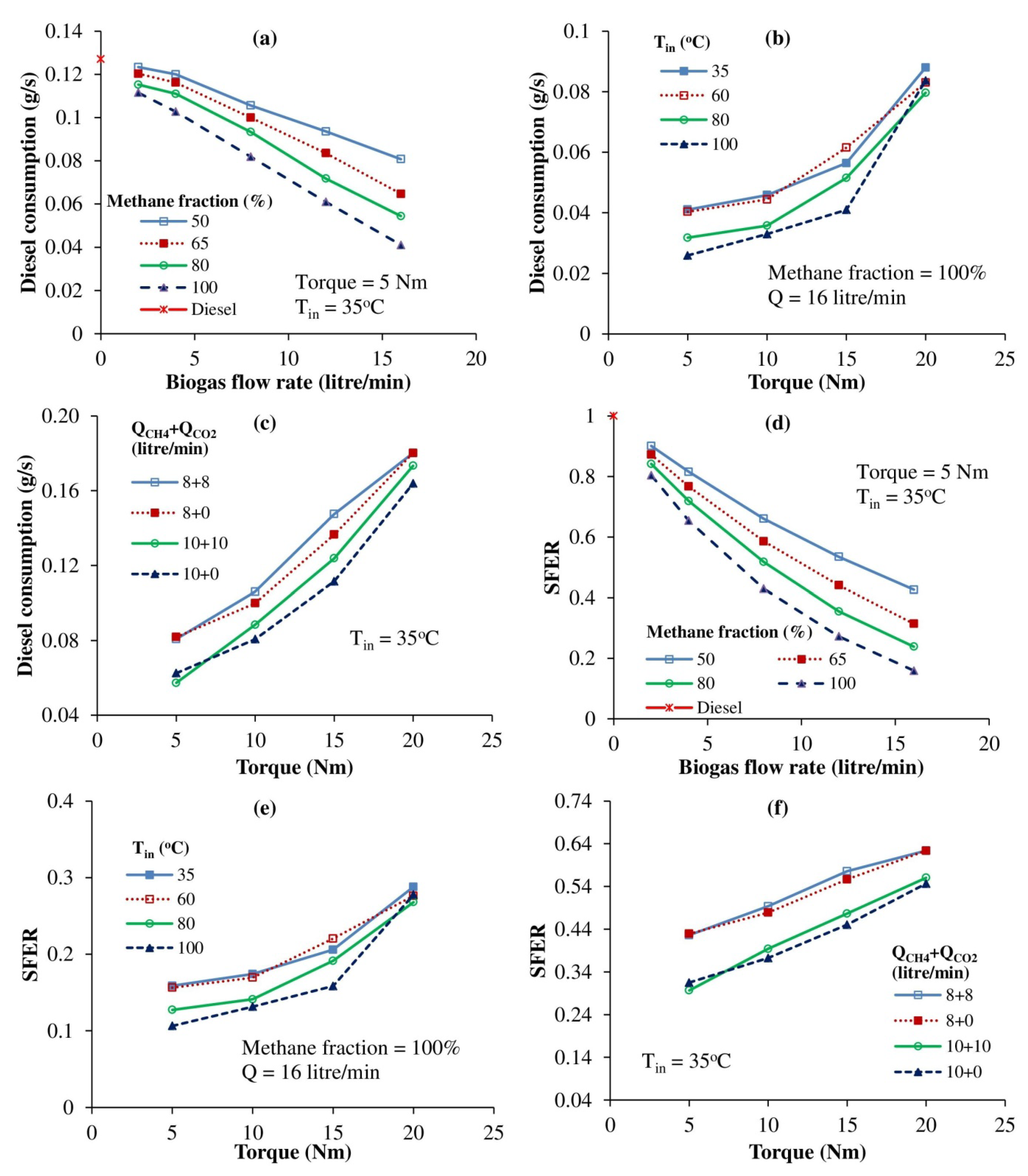
8.1. Diesel Consumption

One of the major objectives of operating the engine in the biogas-diesel dual fuel mode was to achieve maximum substitution of diesel with biogas. Figure 3a shows the variations of diesel consumption for diesel-only and dual fuel operation for different biogas flow rates and methane fractions for a constant operating torque of 5 Nm. As the methane fraction and biogas flow rate are increased, the energy share of biogas increases so that the engine speed is maintained at 1900 rpm by controlling the diesel supply through the governor mechanism. At high biogas flow rates, diesel consumption is reduced by as much as 67% compared to diesel-only mode. At normal intake temperatures, some quantity of biogas in the combustion chamber remains partly burned. Manifold heating (increasing the intake temperature) makes biogas-air mixtures more combustible and hence provides better diesel substitution. This is especially useful at low loads, where operating temperatures are low. For instance, at the torque value of 5 Nm, raising the temperature of charge from 35 °C to 100 °C reduces diesel consumption by 35% (refer Figure 3b). As expected, an increase in torque required more fuel (diesel) to run at constant rpm and hence increases the fuel consumption as shown in Figure 3b. Methane enrichment (complete removal of CO2) improves biogas combustion and hence causes a minor reduction in diesel consumption (~5.5% for 10 L/min of methane flow rate) as shown in Figure 3c.

8.2. Secondary Fuel Energy Ratio

SFER is the ratio of the energy supplied by diesel to the total fuel (biogas + diesel) energy. Diesel substitution resulted in a reduction in SFER. Increases in methane fraction and biogas flow rate reduce diesel consumption as discussed in Section 8.1 and hence cause a drop in SFER. Figure 3d shows that the SFER in dual mode can be as low as 10%. Figure 3e shows the relationship between SFER, intake temperature, and torque for a fixed flow rate of biogas (16 lpm) and methane fraction (100%). An increase in torque causes the governor mechanism to supply more diesel, thus increasing the SFER. As biogas combustion releases more energy at higher temperatures, SFER reduces with intake heating. It also decreases slightly with methane enrichment due to improvement in combustion (see Figure 3f).

8.3. Brake Thermal Efficiency

Both the primary fuel (biogas) flow rate and a fraction of methane in the simulated biogas mixture can influence the brake thermal efficiency of the CI engine and the same is presented in Figure 4a for the engine torque of 5 Nm and at its intake temperature of 35 °C. It can be observed that the highest brake thermal efficiency is obtained with the lowest biogas flow rate (2 L/min), confirming earlier findings [7,43,44]. This is due to the fact that biogas partially replaces the excess air, which otherwise remains unutilized and contributes to the pumping loss. Low biogas flow rates are hence beneficial. However, as the biogas flow rate is increased, the displacement of air can occur to the extent that the methane supplied remains incompletely burned, causing a reduction in efficiency. Methane fraction has no influence on efficiency at low biogas flow rates. At high biogas flow rates, high methane fraction results in more diesel substitution, which reduces the ignition quality of the air-fuel mixture. The energy content of the unburned fuel lost via the exhaust is increased. Consequently, the thermal efficiency deteriorates with an increase in methane fraction. Nearly a 12% reduction in efficiency is recorded at a high biogas flow rate compared to the diesel-only mode. An increase in methane concentration to 100% in biogas from 50% caused a reduction in efficiency closely by 2.5%.
Figure 4b illustrates the comparison of the BTE with torque and intake charge temperature. High coolant loss and reduced power output are the main reasons for low brake thermal efficiency at low loads, as in conventional CI operation. Thermal efficiency improves with an increase in load as there is a better conversion of fuel energy to useful work. BTE is found to increase up to 2% with manifold heating of the intake charge. This is due to the higher degree of completeness of biogas combustion at elevated temperatures [44].
Figure 4c depicts the variation of the BTE with methane enrichment. The removal of CO2 improves air intake and the quality of combustion. Consequently, a slight improvement (2.5% at high load for 10 L/min of methane flow rate, compared to raw biogas with 50% methane fraction) in efficiency is observed.

8.4. Air-Fuel Ratio

As the biogas flow rate is increased, the total mass flow rate of fuel increases in spite of a small reduction in the diesel flow rate. Increasing the biogas flow rate also displaces more air in the intake, reducing the mass of inducted air. An increase in the biogas flow rate caused a net effect of a reduction in the air-fuel ratio. Raw biogas has a significant amount of CO2 which is denser than CH4. By increasing the methane fraction of biogas, the mass of biogas reduces. The diesel supply also drops, as discussed in Section 8.1. Consequently, methane enrichment enhances the air-fuel ratio.
At higher loads, the governor mechanism supplies more diesel, causing a drop in the air-fuel ratio with torque. An increase in temperature reduces the density of intake air and consequently its mass, rendering the overall mixture leaner. The removal of CO2 reduces the mass of biogas while admitting more air, thus increasing the air-fuel ratio.

8.5. Equivalence Ratio

Figure 4d shows the effects on the overall equivalence ratio by the methane fraction and biogas flow rate at constant torque and intake temperature. The fresh air displaced during biogas induction increases the overall equivalence ratio. While increasing the methane fraction enhances the AFR as discussed in Section 8.4, the stoichiometric air-fuel ratio is also found to be increased.
Figure 4e shows the effects of intake temperature and torque on the overall equivalence ratio under constant methane fraction and biogas flow rate. An increase in torque raises the ER due to a higher amount of injected diesel and reduced air inflow. As manifold heating reduces the density of air, the overall equivalence ratio increases with temperature. The relationship between methane enrichment and the overall equivalence ratio is shown in Figure 4f. Removal of CO2 increases the air-fuel ratio and decreases diesel consumption, as discussed in Section 8.1. Consequently, methane enrichment reduces the overall equivalence ratio.

8.6. HC Emissions

One of the main causes of HC emissions is the incomplete combustion of fuel. Entrapment of fuel in crevice volumes and short-circuiting during the intake process also contribute to HC emissions. The effects of methane fraction and biogas flow rate on HC emissions are shown in Figure 5a. Both these factors reduce the diesel inflow and raise the overall equivalence ratio, as discussed in Section 8.1 and Section 8.5. The short supply of diesel, which initiates combustion, reduced availability of fresh air, the higher self-ignition temperature of biogas, and its lower flame speed adversely affect the completeness of combustion. Methane which remains unburned escapes via the exhaust and is recorded as HC emission [7]. The increased ID of biogas combustion has also been cited as one of the reasons for high HC emissions [45].
Figure 5b depicts the effects on HC emissions due to the torque and intake temperature. At low loads and intake temperatures, the biogas-air mixture is very lean and the flame propagation is very slow. Under these conditions, premature flame quenching causes unburned HC emissions [16]. At high loads, high in-cylinder temperature and mixtures closer to stoichiometric proportions tend to improve the performance of combustion and lower the HC emissions. The HC emissions for raw and methane-enriched biogas are compared in Figure 5c. Eliminating CO2 enhances the flame velocity, increases the temperature, widens the flammability limits, and improves HC emissions [29]. The effect of methane enrichment in mitigating HC emissions is especially significant at low loads.

8.7. CO Emission

The main reason for the emission comprising CO is incomplete combustion due to a lack of available oxygen, which causes some of the carbon in the fuel to be only partially oxidized. The amount of CO, for a range of fuel compositions and C/H ratios, is a strong function of the equivalence ratio. The variations in the CO emission for different biogas flow rates at 5 Nm and 35 °C are shown in Figure 5d. The increase in CO levels with biogas flow rate can be attributed to the relatively higher equivalence ratios under these conditions (see Section 8.5). No clear trend was observed in the case of methane fraction.
Figure 5e illustrates the variations of CO emission with load and intake temperature. In the experimental data, CO emissions in % volume basis were found to increase with torque on account of the increase in overall equivalence ratio. However, when expressed in terms of g/kWh, the emissions showed an initial downward trend as the increase in brake power offsets the effect of increased CO formation. The slow increase in brake-specific CO emission in the figure reflects a sharp rise in CO formation close to peak load conditions due to insufficient air. An increase in temperature improves biogas combustion as discussed before and hence lowers CO emission levels [44].
Figure 5f illustrates the effectiveness of methane enrichment in curbing CO emissions. Biogas combustion proceeds to a greater degree of completion when CO2 is removed owing to the increased availability of oxygen and higher flame speed.

8.8. NOx Emissions

The three main mechanisms of NOx formations are thermal NOx, fuel NOx and prompt NOx. NOx emission formation depends strongly on combustion temperature and the availability of oxygen. The thermal mechanism is the most dominant in CI engines. It is described by the extended Zeldovich reaction mechanism [37]:
N2 + O = NO + N
N + O2 = NO + O
N + OH = NO + H
Some of the NO is subsequently oxidized further to form NO2.
Figure 6a shows the effects of methane fraction and biogas flow rate on NOx emissions. An increase in biogas flow rate reduces diesel consumption, which lowers the in-cylinder temperature on account of the lower flame speed and calorific value of biogas. Higher biogas intake also suppresses the air inflow. The net effect is to bring down NOx emissions in general. On the other hand, an increase in methane fraction enhances in-cylinder temperatures and promotes NOx formation.
The influence of torque and intake temperature over NOx emissions is shown in Figure 6b. Both these factors raise combustion temperatures and hence NOx emissions. Figure 6c depicts the relationship between methane enrichment and NOx emission. Removal of CO2 increases in-cylinder temperature and generates more NOx. The diluent effect of CO2 in raw biogas has an effect similar to EGR in bringing down NOx levels.

8.9. Smoke Emissions

Locally fuel-rich pockets, burning of lubricating oil, and carbon deposits (soot) are the primary sources of smoke emissions. A high concentration of PM is manifested as the visible smoke that emanates from the exhaust of the engine. Reduction in soot emissions is proportional to diesel substitution.
Figure 6d shows the effects on smoke emissions by the biogas flow rate and methane fraction. An increase in biogas flow rate and methane fraction increases the diesel substitution. The presence of methane, which is the lowest member in the paraffin family, results in a more homogeneous fuel-air mixture and reduces the extent of diffusion combustion of diesel. This and the reduced wall impingement of diesel mitigate smoke emissions.
The effects of both torque and the engine’s intake temperature on the emissions are depicted in Figure 6e. Smoke emission increases with the rise in load on account of more diesel injection, resulting in more rich pockets within the fuel. Smoke levels are lower with intake charge heating, possibly because the elevated temperatures aid the vaporization of diesel as well as soot oxidation.
The relations between methane enrichment and smoke emissions are shown in Figure 6f. As discussed in Section 8.1 and Section 8.5, methane enrichment reduces diesel consumption and the overall equivalence ratio. Hence, smoke emissions are observed to be slightly lower in most cases compared to raw biogas.

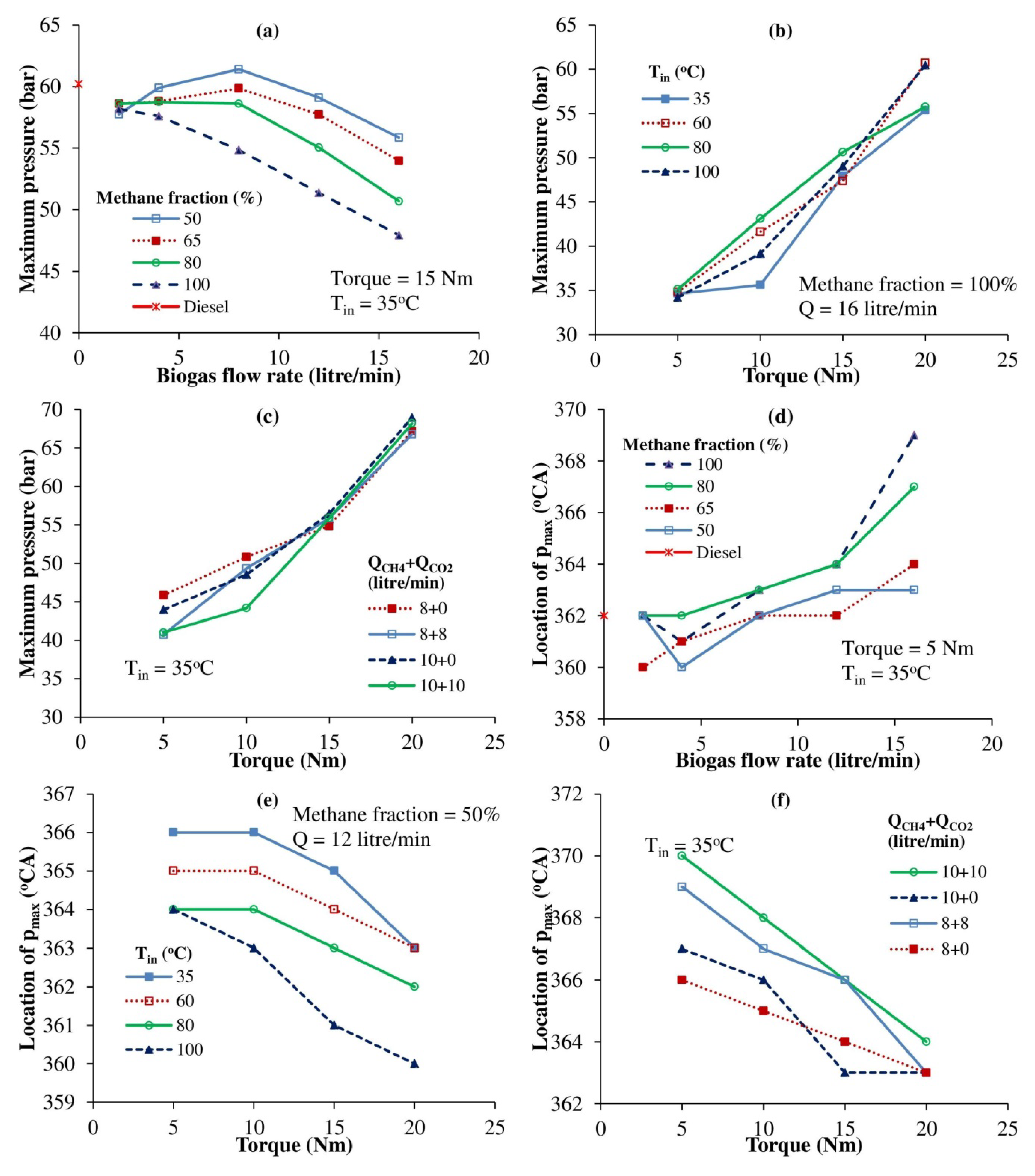
8.10. Maximum Cylinder Pressure

The effects of methane fraction and biogas flow rate on maximum cylinder pressure are shown in Figure 7a. Low biogas flow rates are associated with better utilization of the available excess air, resulting in faster heat release and higher peak pressure. However, high flow rates of biogas and methane concentrations result in greater diesel substitution, which in turn lowers the rate of combustion and energy release vis-à-vis diesel, as methane is a less reactive fuel with a very low cetane number. Figure 8 shows the pressure histories.
Figure 7b captures the effect of engine torque and the engine’s intake temperature on its maximum pressure in the cylinder. An increase in load increases the quantity of injected fuel, burning rate, energy release, and working fluid temperature, which in turn increases cylinder pressure. An increase in temperature reduces both diesel consumption and air supply, as discussed in Section 8.1 and Section 8.4, thus bringing down the net heat release, which tends to reduce in-cylinder temperature and pressure. However, a higher initial temperature tends to cause a corresponding increase in the temperatures and pressures during combustion by virtue of the conservation of energy and the equation of state. Owing to these opposing effects, the concrete trend is not witnessed between peak pressure and intake temperature (refer to Figure 7b).
The variation in the maximum cylinder pressure with methane enrichment of biogas is shown in Figure 7c. Removal of CO2 is observed to enhance peak pressure at low and medium loads. Methane enrichment has a negligible effect at high engine loads since much of the energy release occurs due to diesel combustion.

8.11. Location of Maximum Cylinder Pressure

The angle of occurrence of peak pressure with respect to TDC (360 °CA) denotes the effectiveness of combustion in producing useful work. A pressure peak slightly after TDC provides more useful work in contrast to delayed (retarded) peak pressure, which denotes late combustion and less useful work output. On the other hand, very early (advanced) peak pressures could denote the occurrence of knock due to very high initial energy release. The effect of the flow rate of biogas and methane concentration on the location of maximum cylinder pressure is shown in Figure 7d. As discussed in Section 8.1, the increase in methane fraction and biogas flow rate reduces diesel consumption, lowering the reaction rate and retarding the angle of occurrence of peak pressure in general. However, advancement is observed in a few cases with low biogas flow rates due to the better utilization of excess air, which enhances the heat release rate.
Figure 7e depicts the effect of torque and intake temperature on the location of maximum cylinder pressure. An increase in load increases the quantity of injected diesel, burning rate, and working fluid temperature, which in turns advances the location of peak pressure. An increase in charge temperature also enhances the burning rate and advances the angle of peak pressure. During methane enrichment, the removal of CO2 increases the reaction rate (and hence the flame velocity) and advances the location of peak pressure as shown in Figure 7f.

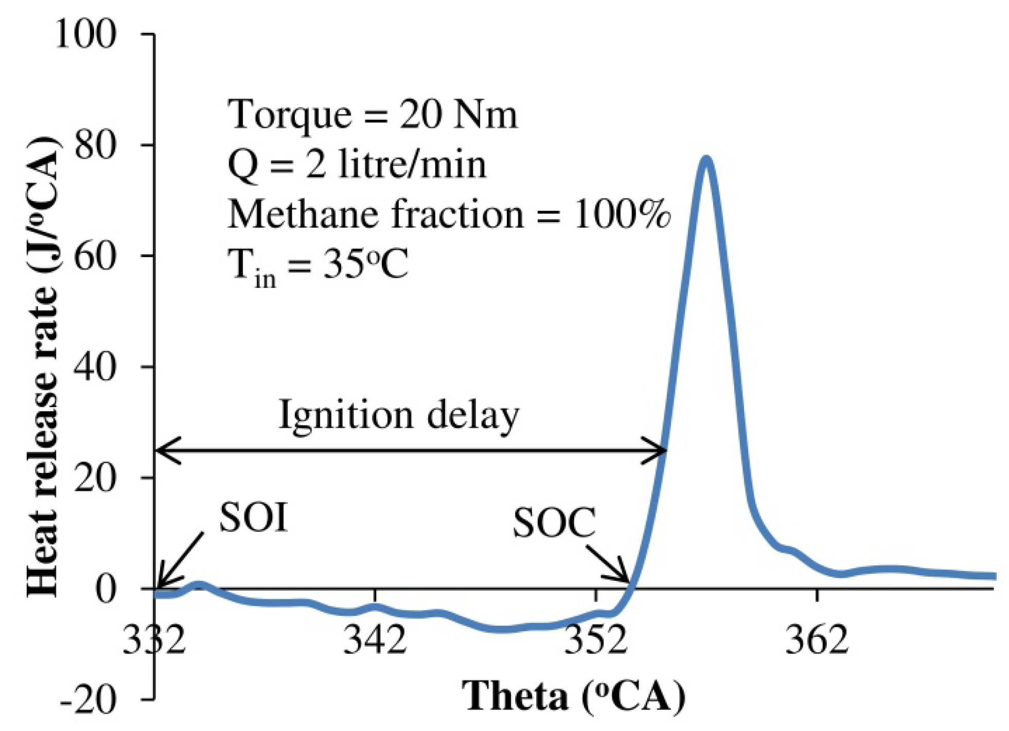
8.12. Ignition Delay

ID is the crank angle interval from the start of injection to the start of combustion. The effects of methane fraction and biogas flow rate on ID are shown in Figure 9a. There are two conflicting factors that affect ID. Methane has a very low cetane number and hence increasing the flow rate of biogas or methane concentration (by vol.) tends to increase the delay period. This effect is prominent at high biogas flow rates. However, at lower values of biogas flow rates, the increased operating temperature and pressure (see Section 8.10) tend to reduce the ID. Consequently, no clear trend is observed for low flow rates (biogas) and methane fractions.
It is known that both the physical and the chemical delay reduce with an increase in operating temperature. Hence, higher torques and intake temperatures are observed to have shorter delay periods, as seen in Figure 9b.
The effect of methane enrichment on ID is shown in Figure 9c. Removal of CO2 reduces the self-ignition temperature of biogas and shortens the ID.

8.13. Maximum Heat Release Rate

A typical heat release rate diagram is shown in Figure 10. The effects of methane fraction and biogas flow rate on MHRR are shown in Figure 9d. As explained in Section 8.10, MHRR shows an initial rise due to the better utilization of excess air. However, at high values of flow rates (biogas) and methane fraction, MHRR tends to drop due to greater diesel substitution, which adversely affects the fuel-air mixture’s reactivity.
Figure 9e shows that with an increase in load, the corresponding increase in the quantity of injected diesel enhances the burning rate, resulting in high MHRR. The graph also reveals that the effect of temperature on MHRR is less significant.
As expected, the removal of CO2 results in higher MHRR owing to the increase in calorific value and flame velocity and reduction in self-ignition temperature (refer to Figure 9f).

9. Conclusions

An experimental investigation was carried out to determine the effects of biogas flow rate and composition, intake temperature, and methane enrichment on the performance, emissions, and combustion characteristics of a CI engine operated in dual fuel mode. An increase in biogas flow rate reduces the brake thermal efficiency, peak cylinder pressure, and heat release rate, while ignition delay, HC, and CO emissions are increased. Biogas is capable of providing a maximum of 90% of the overall energy input, thus reducing diesel consumption by nearly 67%. This also lowers NOx and smoke emissions by up to 75% and 55%, respectively. Methane enrichment increases heat release rate and improves brake thermal efficiency marginally. Diesel consumption can be up to 5.5% lower with methane enrichment. HC, CO emissions are also reduced. Intake heating can enhance brake thermal efficiency by up to 2% and reduce diesel consumption by up to 35%. It also lowers all emissions except NOx. Simultaneously, increasing the biogas flow rate, methane fraction, and intake temperature minimizes smoke emissions. Methane enrichment and manifold heating emerge as viable methods to improve the performance and emissions in the dual fuel mode.

Author Contributions

Conceptualization, M.F. and S.I.; methodology, M.F., S.I. and G.N. validation M.F., S.I., S.M., and G.N. formal analysis, M.F., S.I., S.M. and G.N. investigation, M.F., S.I., S.M. and G.N.; resources, M.F., T.M.Y.K., M.A.A. and S.D.A.K.; data curation, M.F. and S.I.; writing—original draft preparation, M.F. and S.I.; writing—review and editing, M.F. and S.I.; supervision, S.I.; funding acquisition, M.F., S.I., T.M.Y.K., M.A.A. and S.D.A.K. All authors have read and agreed to the published version of the manuscript.

Funding

This work was funded by King Khalid University under grant number R.G.P. 1/214/43.

Institutional Review Board Statement

Not applicable.

Informed Consent Statement

Not applicable.

Data Availability Statement

Data is contained within the article.

Acknowledgments

The authors extend their appreciation to the Deanship of Scientific Research at King Khalid University, Saudi Arabia for funding this work through the Research Group Program under Grant Number: R.G.P. 1/214/43.

Conflicts of Interest

The authors declare no conflict of interest.

References

  1. Komninos, N.P.; Rakopoulos, C.D. Modeling HCCI combustion of biofuels: A review. Renew. Sustain. Energy Rev. 2012, 16, 1588–1610. [Google Scholar] [CrossRef]
  2. Tippayawong, N.; Thanompongchart, P. Biogas quality upgrade by simultaneous removal of CO2 and H2S in a packed column reactor. Energy 2010, 35, 4531–4535. [Google Scholar] [CrossRef]
  3. Demirbas, A. Combustion characteristics of different biomass fuels. Prog. Energy Combust. Sci. 2004, 30, 219–230. [Google Scholar] [CrossRef]
  4. Demirbas, M.F.; Balat, M.; Balat, H. Biowastes-to-biofuels. Energy Convers. Manag. 2011, 52, 1815–1828. [Google Scholar] [CrossRef]
  5. Khoiyangbam, N.R.; Gupta, N.; Kumar, S. Biogas Technology: Towards Sustainable Development, the Energy and Resources Institute (TERI). 2011. Available online: https://books.google.com/books?hl=en&lr=&id=5ALjQDcrzBQC&pgis=1 (accessed on 10 January 2016).
  6. Ibrahim, M.M.; Narasimhan, J.V.; Ramesh, A. Comparison of the predominantly premixed charge compression ignition and the dual fuel modes of operation with biogas and diesel as fuels. Energy 2015, 89, 990–1000. [Google Scholar] [CrossRef]
  7. Barik, D.; Murugan, S. Investigation on combustion performance and emission characteristics of a DI (direct injection) diesel engine fueled with biogas-diesel in dual fuel mode. Energy 2014, 72, 760–771. [Google Scholar] [CrossRef]
  8. Cacua, K.; Amell, A.; Cadavid, F. Effects of oxygen enriched air on the operation and performance of a diesel-biogas dual fuel engine. Biomass Bioenerg. 2012, 45, 159–167. [Google Scholar] [CrossRef]
  9. Bora, B.J.; Saha, U.K.; Chatterjee, S.; Veer, V. Effect of compression ratio on performance, combustion and emission characteristics of a dual fuel diesel engine run on raw biogas. Energy Convers. Manag. 2014, 87, 1000–1009. [Google Scholar] [CrossRef]
  10. Porpatham, E.; Ramesh, A.; Nagalingam, B. Investigation on the effect of concentration of methane in biogas when used as a fuel for a spark ignition engine. Fuel 2008, 87, 1654–1659. [Google Scholar] [CrossRef]
  11. Ryckebosch, E.; Drouillon, M.; Vervaeren, H. Techniques for transformation of biogas to biomethane. Biomass Bioenerg. 2011, 35, 1633–1645. [Google Scholar] [CrossRef]
  12. Feroskhan, M.; Thangavel, V.; Subramanian, B.; Sankaralingam, R.K.; Ismail, S.; Chaudhary, A. Effects of operating parameters on the performance, emission and combustion indices of a biogas fuelled HCCI engine. Fuel 2021, 298, 120799. [Google Scholar] [CrossRef]
  13. Lounici, M.S.; Loubar, K.; Tazerout, M.; Balistrou, M.; Tarabet, L. Experimental investigation on the performance and exhaust emission of biogas-diesel dual-fuel combustion in a CI engine. In Proceedings of the SAE 2014 International Powertrain, Fuels & Lubricants Meeting, Birmingham, AL, USA, 20–23 October 2014. [Google Scholar] [CrossRef]
  14. Verma, S.; Das, L.M.; Kaushik, S.C. Effects of varying composition of biogas on performance and emission characteristics of compression ignition engine using exergy analysis. Energy Convers. Manag. 2017, 138, 346–359. [Google Scholar] [CrossRef]
  15. Kalsi, S.S.; Subramanian, K.A. Effect of simulated biogas on performance, combustion and emissions characteristics of a bio-diesel fueled diesel engine. Renew. Energy. 2017, 106, 78–90. [Google Scholar] [CrossRef]
  16. Duc, P.M.; Wattanavichien, K. Study on biogas premixed charge diesel dual fuelled engine. Energy Convers. Manag. 2007, 48, 2286–2308. [Google Scholar] [CrossRef]
  17. Nathan, S.S.; Mallikrajuna, J.M.; Ramesh, A. Homogeneous charge compression ignition versus dual fuelling for utilizing biogas in compression ignition engines. Proc. Inst. Mech. Eng. Part D J. Automob. Eng. 2009, 223, 413–422. [Google Scholar] [CrossRef]
  18. Verma, S.; Das, L.M.; Kaushik, S.C.; Bhatti, S.S. The effects of compression ratio and EGR on the performance and emission characteristics of diesel-biogas dual fuel engine. Appl. Therm. Eng. 2019, 150, 1090–1103. [Google Scholar] [CrossRef]
  19. Huang, Y.; Surawski, N.C.; Zhuang, Y.; Zhou, J.L.; Hon, G. Dual injection: An effective and efficient technology to use renewable fuels in spark ignition engines. Renew. Sustain. Energy Rev. 2021, 143, 110921. [Google Scholar] [CrossRef]
  20. Sharma, A.; Ahmad, N.; Pal, A.; Singh, Y.; Lalhriatpuia, S. Effect of biogas on the performance and emissions of diesel engine fuelled with biodiesel-ethanol blends through response surface methodology approach. Renew. Energy 2019, 141, 657–668. [Google Scholar] [CrossRef]
  21. Debnath, B.K.; Bora, B.J.; Sahoo, N.; Saha, U.K. Influence of emulsified palm biodiesel as pilot fuel in a biogas run dual fuel diesel engine. J. Energy Eng. 2014, 140, A4014005. [Google Scholar] [CrossRef]
  22. Oishi, Y. Performance, rate of heat release, and combustion stability of dual-fuel mode in a small diesel engine. Energy Sci. Eng. 2019, 7, 1333–1351. [Google Scholar] [CrossRef]
  23. Goga, G.; Chauhan, B.S.; Mahla, S.K.; Dhir, A. Environmental effects combined impact of varying biogas mass flow rate and rice bran methyl esters blended with diesel on a dual-fuel engine. Energy Sources Part A Recover. Util. Environ. Eff. 2019, 43, 120–132. [Google Scholar] [CrossRef]
  24. Murali, R.; Stalin, N.; Ravikumar, P. Environmental effects performance studies and emission analysis of azolla and corn husk biogas powered dual fuel mode compression ignition engine. Energy Sources Part A Recover. Util. Environ. Eff. 2019, 41, 2808–2820. [Google Scholar] [CrossRef]
  25. Yoon, S.H.; Lee, C.S. Experimental investigation on the combustion and exhaust emission characteristics of biogas-biodiesel dual-fuel combustion in a CI engine. Fuel Process. Technol. 2011, 92, 992–1000. [Google Scholar] [CrossRef]
  26. Feroskhan, M.; Ismail, S.; Reddy, M.G.; Teja, A.S. Effects of charge preheating on the performance of a biogas-diesel dual fuel CI engine, Eng. Sci. Technol. Int. J. 2018, 21, 330–337. [Google Scholar] [CrossRef]
  27. Bedoya, I.D.; Saxena, S.; Cadavid, F.J.; Dibble, R.W.; Wissink, M. Experimental study of biogas combustion in an HCCI engine for power generation with high indicated efficiency and ultra-low NOx emissions. Energy Convers. Manag. 2012, 53, 154–162. [Google Scholar] [CrossRef]
  28. Henham, A.; Makkar, M.K. Combustion of simulated biogas in a dual-fuel diesel engine. Energy Convers. Manag. 1998, 39, 2001–2009. [Google Scholar] [CrossRef]
  29. Mustafi, N.N.; Raine, R.R.; Verhelst, S. Combustion and emissions characteristics of a dual fuel engine operated on alternative gaseous fuels. Fuel 2013, 109, 669–678. [Google Scholar] [CrossRef] [Green Version]
  30. Harilal, H.J.Y.; Sorathia, S. Energy Analyses to a Ci-Engine Using Diesel and Bio-Gas Dual Fuel—A Review Study. Int. J. Adv. Eng. Res. Stud. 2012, 1, 212–217. [Google Scholar]
  31. Sahoo, B.B.; Sahoo, N.; Saha, U.K. Effect of engine parameters and type of gaseous fuel on the performance of dual-fuel gas diesel engines—A critical review. Renew. Sustain. Energy Rev. 2009, 13, 1151–1184. [Google Scholar] [CrossRef]
  32. Luijten, C.C.M.; Kerkhof, E. Jatropha oil and biogas in a dual fuel CI engine for rural electrification. Energy Convers. Manag. 2011, 52, 1426–1438. [Google Scholar] [CrossRef]
  33. Shan, X.; Qian, Y.; Zhu, L.; Lu, X. Effects of EGR rate and hydrogen/carbon monoxide ratio on combustion and emission characteristics of biogas/diesel dual fuel combustion engine. Fuel. 2016, 181, 1050–1057. [Google Scholar] [CrossRef]
  34. Rahman, K.A.; Ramesh, A. Studies on the effects of methane fraction and injection strategies in a biogas diesel common rail dual fuel engine. Fuel 2019, 236, 147–165. [Google Scholar] [CrossRef]
  35. Barik, D.; Sivalingam, M. Performance and Emission Characteristics of a Biogas Fueled DI Diesel Engine. 2013. Available online: http://papers.sae.org/2013-01-2507/ (accessed on 10 January 2016).
  36. Polk, A.C.; Gibson, C.M.; Shoemaker, N.T.; Srinivasan, K.K.; Krishnan, S.R. Analysis of Ignition Behavior in a Turbocharged Direct Injection Dual Fuel Engine Using Propane and Methane as Primary Fuels. J. Energy Resour. Technol. 2013, 135, 032202. [Google Scholar] [CrossRef]
  37. Königsson, F.; Stalhammar, P.; Angstrom, H.-E. Characterization and Potential of Dual Fuel Combustion in a Modern Diesel Engine. SAE Tech. Pap. 2011, 2011. [Google Scholar] [CrossRef]
  38. Yilmaz, I.T.; Gumus, M. Investigation of the effect of biogas on combustion and emissions of TBC diesel engine. Fuel 2017, 188, 69–78. [Google Scholar] [CrossRef]
  39. Ray, N.H.S.; Mohanty, M.K.; Mohanty, R.C. A Study on Application of Biogas as fuel in Compression Ignition Engines. Int. J. Innov. Eng. Technol. 2013, 3, 239–245. [Google Scholar]
  40. Park, S.H.; Yoon, S.H. Effect of dual-fuel combustion strategies on combustion and emission characteristics in reactivity controlled compression ignition (RCCI) engine. Fuel 2016, 181, 310–318. [Google Scholar] [CrossRef]
  41. Moffat, R.J. Describing the uncertainties in experimental results. Exp. Therm. Fluid Sci. 1988, 1, 3–17. [Google Scholar] [CrossRef] [Green Version]
  42. Pilusa, T.J.; Mollagee, M.M.; Muzenda, E. Reduction of vehicle exhaust emissions from diesel engines using the whale concept filter. Aerosol Air Qual. Res. 2012, 12, 994–1006. [Google Scholar] [CrossRef] [Green Version]
  43. Feroskhan, M.; Ismail, S.; Gosavi, S.; Tankhiwale, P. Optimization of performance and emissions in a biogas—diesel dual fuel engine with cerium oxide nanoparticle addition. Proc. Inst. Mech. Eng. Part D J. Automob. Eng. 2018, 223, 1178–1193. [Google Scholar] [CrossRef]
  44. Feroskhan, M.; Ismail, S.; Panchal, S.H. Study of methane enrichment in a biogas fuelled HCCI engine. Int. J. Hydrog. Energy 2022, 47, 3504–3514. [Google Scholar] [CrossRef]
  45. Park, S.H.; Yoon, S.H.; Cha, J.; Lee, C.S. Mixing effects of biogas and dimethyl ether (DME) on combustion andemission characteristics of DME fueled high-speed diesel engine. Energy 2014, 66, 413–422. [Google Scholar] [CrossRef]
Figure 1. (a) photograph and (b) Schematic diagram of the experimental setup.
Sustainability 15 01232 g001
Figure 2. Estimation of ignition delay from heat release rate vs. crank angle diagram.
Sustainability 15 01232 g002
Figure 3. Effects of various parameters on diesel consumption and SFER.
Sustainability 15 01232 g003
Figure 4. Effects of various parameters on brake thermal efficiency and equivalence ratio.
Sustainability 15 01232 g004
Figure 5. Effects of various parameters on HC and CO emissions.
Sustainability 15 01232 g005
Figure 6. Effects of various parameters on NOx and smoke emissions.
Sustainability 15 01232 g006
Figure 7. Effects of various parameters on maximum pressure and location of maximum pressure.
Sustainability 15 01232 g007
Figure 8. Cylinder pressure histories.
Sustainability 15 01232 g008
Figure 9. Effects of various parameters on ignition delay and maximum HRR.
Sustainability 15 01232 g009
Figure 10. Heat release rate diagrams.
Sustainability 15 01232 g010
Table 1. Engine specifications.
ParameterValue
Bore and stroke87.5 mm and 80 mm
Cubic capacity481 cm3
Peak pressure7500 kPa
Combustion principleCompression ignition
Working cycle4-stroke diesel
Compression ratio17:1
Number of cylinders and Arrangement1-Vertical
Maximum power5.97 kW
Maximum torque25 Nm
Number of nozzle holes3
Operating speed range1500–2200 rpm
Speed controlGovernor mechanism
Injector opening pressure210 bar
Table 2. Details of the measuring instruments.
Quantity MeasuredMeasuring DeviceLeast Count
Flow rate of CH4Thermal mass flow meter0.1 L/min
Flow rate of CO2Thermal mass flow meter0.1 L/min
TorqueEddy current dynamometer0.1 Nm
TemperatureThermocouples0.1 °C
Flow rate of neat dieselBurette0.2 mL
Crank angleAngle encoder1 °CA
Air flow rateOrifice meter0.00006 m3/s
Smoke emissionsAVL 437C smoke meter0.1%
CO emissionAVL DiGas 444N gas analyser0.01%
HC emissions1 ppm
NOx emissions10 ppm
In-cylinder pressurePressure sensor33 pC/bar
Table 3. Uncertainty estimates of the output parameters.
Output ParameterUncertainty (±)
CO emission3%
HC emissions3%
Brake thermal efficiency2.46%
Cylinder pressure2%
Volumetric efficiency1.91%
Equivalence ratio1.51%
Secondary fuel energy ratio1.33%
Diesel consumption1%
Smoke emissions1%
NOx emissions1%
Table 4. Operating parameters.
Torque
(Nm)
Biogas Flow Rate,
Qbg
(L/min)
Methane Fraction
(%)
Intake Temperature, Tin
(°C)
5 to 20
(5, 10, 15 and 20)
2 to 16
(2, 4, 8, 12 and 16)
50 to 100
(50, 65, 80 and 100)
35 to 100
(35, 60, 80 and 100)
Table 5. Range of torque and BMEP.
Torque (Nm)Percentage of Full Load (%)BMEP (bar)
522.51.31
10452.61
1567.53.93
20905.23
Disclaimer/Publisher’s Note: The statements, opinions and data contained in all publications are solely those of the individual author(s) and contributor(s) and not of MDPI and/or the editor(s). MDPI and/or the editor(s) disclaim responsibility for any injury to people or property resulting from any ideas, methods, instructions or products referred to in the content.

