1. Introduction
In recent years, due to in-depth research into computer technology, alternating current (AC) frequency conversion technology, and high-performance permanent magnet materials, PMSM has developed rapidly and has gradually become a new trend in the development and application of elevator drive systems [
1]. With the widespread application of elevator traction machines (including brakes), the service life of traction machines has become longer and their failure rate has increased gradually [
2,
3,
4]. Compared with traditional worm and worm traction machines driven by a three-phase AC asynchronous motor, PMSMs have the characteristics of a more straightforward structure and smaller size. They can be widely used in elevator products without machine rooms or in elevators with small machine rooms [
5,
6,
7]. However, they also have the disadvantages of complex maintenance and troubleshooting. If a failure in a main engine driven by a PMSM is not checked in time, it can easily lead to significant elevator failures or accidents. This paper introduces a detection method for loss of excitation faults in elevator traction PMSMs based on a new high-order sliding mode flux observer [
8].
Research on sliding mode control began in the 1950s [
9]. It has the advantages of strong system robustness and fast response speed, and has been gradually accepted by researchers and engineers [
10,
11,
12,
13]. After long-term research, researchers and engineers at home and abroad have successfully applied the sliding mode control theory to the control of PMSMs, and it has shown good control performance [
14,
15,
16,
17,
18]. Chen D et al. designed a complete high-order terminal sliding mode controller using q-axis voltage to track the position of a PMSM servo drive system [
19,
20]. Fan Ying et al. constructed a new sliding mode controller that uses the inverse hyperbolic sinusoidal function as the variable speed reaching law. By combining the new sliding mode controller with PI control, the hybrid speed controller can effectively solve the contradiction between fast-starting response speed and excessive starting current, and suppress the steady-state torque ripple [
21]. Zheng Meiru et al. designed an integral time-varying sliding mode controller based on the fractional order to improve the performance of traditional sliding mode control. Han Weimin et al. developed a sliding mode observer based on the exponential approach rate to reduce torque ripple [
22]. Cheema et al. designed an integral sliding mode controller to monitor the flux and speed of a PMSM [
23]. Liu Jing et al. designed a current-adaptive sliding mode control method based on a disturbance observer to improve the anti-interference ability of the system. Tan Fengren et al. designed a new equivalent fuzzy sliding mode observer. They combined it with an improved software phase-locked loop to accurately obtain the motor speed and rotor position. Lu Jun designed a direct speed observer for PMSMs based on the sliding mode control method to improve the accuracy of speed dynamic monitoring. Zhao Kaihui et al. constructed a fast terminal sliding mode observer to monitor the demagnetization fault of a permanent rotor magnet online. He Jing et al. monitored the rotor permanent magnet flux linkage and reconstructed the loss of excitation fault by combining a more extended observer and a sliding mode observer [
24]. Zhang Changfan et al. used a sliding mode observer to monitor the rotor permanent magnet flux, and used the obtained rotor permanent magnet flux in a fault-tolerant predictive control algorithm to realize the current fault-tolerant predictive control of PMSMs. Zhang Yongjun et al. constructed an improved sliding mode observer to monitor PMSMs’ speed and used the Lyapunov function to monitor the resistance in real time. Zhang Changfan et al. designed a cascade adaptive sliding mode observer to monitor the stator resistance parameters and fed the obtained parameters back into the control system for flux linkage reconstruction. This sliding mode control method could better monitor the parameters of PMSMs [
25,
26].
This paper takes PMSMs as the research object. When a PMSM runs under various complex working conditions, the rotor permanent magnet loses its magnetism or the stator resistance parameters change simultaneously [
27]. This paper aims to design an ideal mathematical model of PMSMs and to accurately monitor the changes in permanent magnet flux linkage to help improve the safety and control performance of PMSMs.
This paper focuses on the use of elevator traction machines that use a high-order sliding mode observer with a mixed approach rate to design a fuzzy controller. Through the simulation analysis of a PMSM during local uniform excitation loss, the changes in the external output torque and other parameters of the loss of excitation traction machine are summarized. Through comparison and analysis, this study provides a reference for the identification and judgment of PMSM loss of excitation faults and verifies the effectiveness of loss of excitation detection based on a sliding mode observer.
2. Design of High-Order Sliding Mode Flux Observer
In practical PMSM applications, the size of the permanent magnet flux linkage is bounded. According to the measurable input u and measurable output y, based on the sliding mode control principle and the proportional integral principle, an integral sliding mode observer is designed to realize the online detection and reconstruction of the permanent magnet flux linkage.
Combining the design principle of SMO and the outstanding characteristics of proportional integral observers, a decoupling coefficient is inserted ωe. The sliding mode term ν is retained, and the integral sliding mode observer expression is obtained.
2.1. Mathematical Model of Elevator Traction PMSMs
The mathematical model of PMSMs on an
αβ axis is:
where
, and
are the terminal voltage, phase current, and back EMF on the
αβ axis, respectively;
and
are the resistance and inductance of the PMSM stator, respectively; and P is the differential operator. The back electromotive force of a PMSM comes from the action of the permanent magnet on the rotor on the stator coil, and its formula is as follows:
where
, and
are the flux linkage, electrical speed, and electrical angle of the PMSM rotor, respectively. The back EMF contains the flux linkage information of the permanent magnet. Therefore, the permanent magnet flux linkage can be realized via the back EMF. The formula is as follows:
Therefore, the permanent magnet flux can be obtained through (3) after obtaining the rotor position and rotor speed. If there is no position sensor, observers can realize the angle observation by using a Luenberger observer, an extended Kalman filter (EKF), a sliding mode observer (SMO), etc.
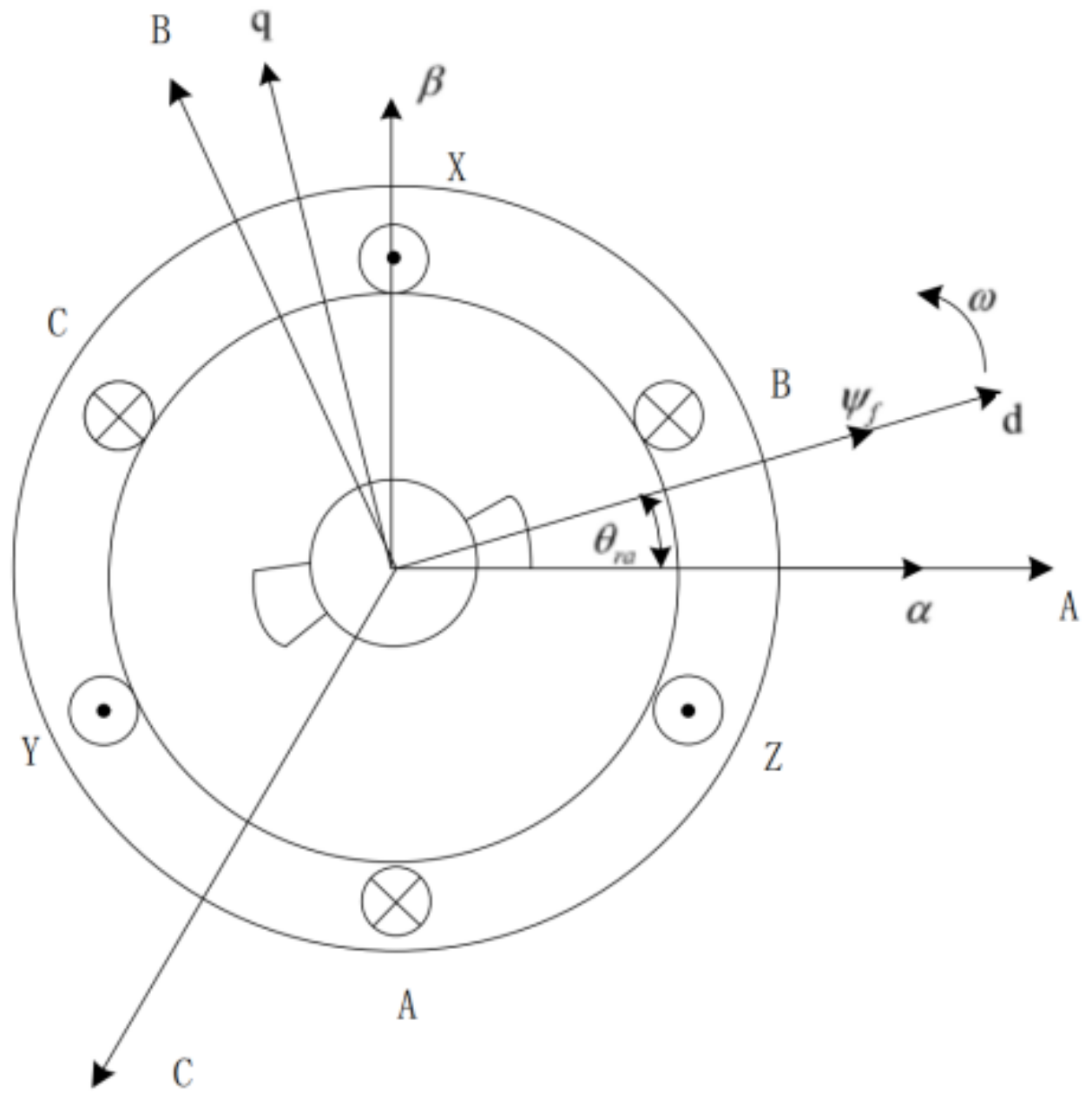
According to Clarke’s principle and Park coordinate transformation, the mathematical models of PMSMs in three different coordinate systems are built, and a mathematical model of PMSMs is constructed.
Figure 1 shows the positional correlation of the three coordinate systems and the high-order sliding mode observer (HSMO) design:
According to Equation (1), the current state equation can be obtained:
A traditional SMO only needs the current equation of state to design, but a HSMO was selected due to the significant noise and delay. HSMOs additionally require the back EMF equation of state, which can be obtained from Equation (2). Since the mechanical constant of a PMSM is much greater than the electrical constant, the change in PMSM speed can be ignored, i.e.,
dωe/
dt = 0. Therefore, the state equation of the back EMF is as follows:
2.2. Design of Sliding Surface and Switching Function
A traditional SMO generally uses the difference between the observed value and the actual value of the stator current of the sliding mode surface, which does not eliminate the influence of the stator resistance on the sliding mode observer. To eliminate the influence of stator resistance, an integral sliding mode surface is used in place of a traditional sliding mode surface, and the integral sliding mode surface is defined as:
where
sα and
sβ are the
sliding surface,
and
are the
observed values of stator current, and
and
are the
actual values of stator current.
The sinusoidal input function is used as the switching function to reduce system buffeting. The equation is:
where
m is a positive constant that is used to control the boundary layer of the switching function.
2.3. Design of Mixed Approach Law
To further reduce system chattering, a new hybrid reaching law is designed:
where
when
k1 > 0,
k2 > 0,
λ > 1.
The new hybrid approach law represented by the
formula is a variable exponential power approach law. When ∣s∣ < 1 and ∣s∣ ≥ 1, the reaching law can be regarded as a power reaching law, which can ensure that the state trajectory of the system converges faster and reduces the system’s
chattering. At the same time, the sinusoidal input function f(s) is used to
replace the traditional symbolic function to reduce the system chattering
further.
The mathematical model of the new sliding mode observer is:
By combining Equations (11) and (12), the equation of stator current error can be obtained as follows:
where
and
are the current observation errors.
2.4. Stability Analysis of Hybrid Reaching Law Sliding Mode Observer
To prove the stability of the hybrid reaching law sliding mode observer system, according to the Lyapunov theorem, the Lyapunov function is defined as:
where
.
According to Lyapunov’s second method, the
stability of the system can be guaranteed only when
. The expression of
the stability condition is:
By combining Equations (14) and (15), we find that that:
According to Equation (16), does not include PMSM stator resistance and deriving k2 satisfies k2 > max (∣eα∣,∣eβ∣).
Therefore, the system is stable.
Because
k2 > max (∣
eα∣,∣
eβ∣), we find
that:
The system satisfies the Lyapunov stability condition when the system state reaches the sliding surface and converges on the equilibrium point:
The system observation can track the back EMF of PMSM over a limited time.
2.5. Design of Fuzzy Controller
The sinusoidal input function image trajectories of different boundary layers are depicted in
Figure 1. It can be seen from
Figure 2 that the larger the control coefficient m of the boundary layer, the thicker the boundary layer. The thickness of the boundary layer is closely related to the buffeting of the system. As the thickness of the boundary layer increases, the chattering of the system decreases. However, the approximation speed of the state trajectory in the sliding mode also decreases, which affects the robustness of the sliding mode observer. Therefore, it is not easy to balance the chattering and robustness of a system with a fixed boundary layer.
To solve this problem, a fuzzy control system is used to adaptively adjust the boundary layer control coefficient m to adaptively adjust the boundary layer thickness of the switching function. It is expressed as follows:
Take s as the input variable and take m as the output variable of the fuzzy control system. When s is large, the control coefficient m should be reduced and the thickness of the boundary layer should be reduced to speed up the approach speed of the state trajectory in the sliding mode; when s is small, the control coefficient m should be increased, and the thickness of the boundary layer should be increased to weaken the chattering of the system.
Define the universe of the input variable s as {−2, 2}, the universe of the output variable m as {0, 3}, the fuzzy language of input quantity as {NH, NB, NM, NS, NL, Z, PL, PS, PM, PB, PH}, and the fuzzy language of output quantity as {Z, PL, PS, PM, PB, PH}. The fuzzy reasoning rules are as follows:
- (1)
if s is Z, then m is PH.
- (2)
if s is NL or PL, then m is PB.
- (3)
if s is NS or PS, then m is PM.
- (4)
if s is NM or PM, then m is PS.
- (5)
if s is NB or PB, then m is PL.
- (6)
if s is NH or PH, then m is Z.
The inference algorithm and the center of gravity method are used to defuzzify the decision. The membership functions of input variable
s and output variable
m are shown in
Figure 3. It can be seen from
Figure 3 and the fuzzy inference rules that when the absolute value of input variable
s is large, the output variable
m decreases and the system approach speed is accelerated; when the absolute value of input variable
s is small, the output variable
m increases to reduce the system chattering.
2.6. Design of Flux Observer
The ^ symbol represents the estimation of the relevant parameters;
h1 and
h2 are the sliding mode gain of the current and back EMF, respectively; and
να,
β is the control input of sliding mode observer (excluding gain). The error equations of the current and back EMF can be obtained through Equations (20) and (21):
According to SMO theory, the convergence condition of the current observation equation can be obtained as follows:
When the current error converges to 0, the error equation of the back EMF can be obtained. After decoupling, it is as follows:
where
He =
h2/(
h1Ls) is the back EMF gain. The same Laplace equation can express the error equation:
where s is the Laplace operator. It can be concluded that the characteristic roots
s1,2 of the back EMF observation are calculated as:
Thus, the dynamic response characteristics of the back EMF can be adjusted by changing the position of the characteristic root. Increasing He can accelerate the convergence speed of the back EMF, but an increase in the PMSM speed will increase the oscillation frequency and overshoot amplitude.
After the accurate back EMF is obtained, the rotor position and speed information can be extracted via the arctangent method or PLL. Taking the arctangent method as an example, the rotor angle is estimated as follows:
The rotation speed of a PMSM can be obtained by deriving the angle of the rotor:
After obtaining the speed information, the estimated value of the rotor permanent magnet flux linkage can be obtained via Equation (27):
3. Simulation Analysis and Experimental Results
The control system for flux linkage parameter monitoring and simulation of PMSM is shown in
Figure 4 and mainly includes a current regulator module, a state observer module, a position and speed detection module, etc. The PMSM control method adopts a high-order sliding mode control strategy. The structure of the elevator PMSM flux parameter observation and control system based on a high-order sliding mode variable structure is shown in
Figure 4 and mainly includes a current regulator module, a loss of excitation reconstruction module, an adaptive module, and a state observer module. The PMSM parameters are shown in
Table 1.
To verify the robustness of the high-order sliding mode observer, three working conditions of low speed full load, high speed full load, and variable speed variable load are set under the conditions of constant and variable inductance of PMSM. The parameters of each working condition are set as shown in
Table 2.
Figure 5 shows the experimental platform for the motor loss of excitation of an elevator PMSM.
In the experiment, the switching frequency is 10 kHz, and the delay coefficient Td of LPF is 1.0 ms. The operating conditions are divided into low speed, high speed, and variable speed. The PMSM is controlled at 2000 Nm and operates at 130 rad/s for high speed between 0 and 2.0 s. Then, the speed drops to the low-speed segment of 200 rad/s. At 6.0 s, the PMSM operates at variable speed, and the speed varies between 40 and 130 rad/s.
Figure 6 shows, the tracking of the actual flux linkage and the reference flux linkage when the elevator is accelerating or decelerating. It can be seen from the figure that the tracking effect of the actual flux linkage is quite poor at low speed and very good at medium and high speeds, which verifies the excellent observation effect of the high-order sliding model flux observer.
In the synchronous rotating coordinate system, a mathematical model of a PMSM with the product of the stator current and the inductance as the state variable is established, and a high-order sliding mode variable structure observer is constructed to monitor the permanent magnet flux linkage of the PMSM. The high-order sliding mode variable structure observer not only has a simple calculation method and strong robustness, but also studies the flux linkage parameter monitoring of sliding mode variable junction PMSMs. The parameters of the observer are easy to choose. The simulation and experimental results verify the feasibility of this method.
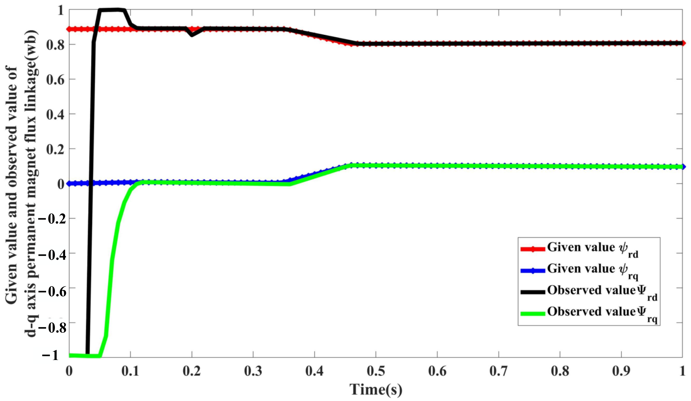
Figure 7 gives the value and the observed value of d-axis permanent magnet flux linkage under the condition of q-axis inductance error.
The adaptive sliding mode observer is discussed under two different normal operations and losses of excitation.
Normal operation: to verify the robustness of the observation, we set the initial value of speed to a = 40 rad/s and increase it from 0.2 to 130 rad/s. When the PMSM starts with a load, we set the initial value of torque to 300 nm and suddenly increase the load torque to 1000 nm in 0.25 s. The PMSM resistance, inductance, and permanent magnet flux linkage are nominal values.
Figure 8a,b shows the waveforms of the inductance parameter adjustment process.
Figure 6 shows the given and observed values of permanent magnet flux linkage. As can be seen from
Figure 8c, under normal conditions, this type of observer can track and estimate the inductance parameters and rotor flux quickly and accurately.
At 0.35 s, the loss of excitation fault occurs in the PMSM, the permanent magnet flux linkage of rotor d axis is reduced from the given initial value of 0.892 wb to 0.8 wb, and a quadrature axis permanent magnet flux linkage component with a size of 0.1 wb appears on the q axis. The AC and DC shaft inductance of the PMSM change simultaneously at 0.5 s, and the DC shaft inductance L increases from a nominal value of 0.001 h to 0.0012 h after 0.1 s. The quadrature axis inductance L decreases from a nominal value of 0.003527 h to 0.003 h after 0.1 s. As is shown in
Figure 7, the adaptive identification system can quickly and accurately identify the system parameters and track the changes in the parameters quickly and accurately. The permanent magnet flux linkage is accurately observed when the parameters of PMSM change at the same time as the loss of excitation.
To further verify the reliability and applicability of this method, the slow change of the permanent magnet flux linkage of a PMSM is observed. As is shown in
Figure 9, the ramp change is used to simulate the slow change of permanent magnet flux linkage. From the figure, we can see that the observed values keep up with the actual given values, which proves the reliability of this type of observer.
To sum up, due to the characteristics of PMSMs and their operating environments, in the actual operation process of a PMSM, the parameters of a PMSM will change with changes in PMSM operating conditions. The traditional sliding mode observer method can be used to observe the rotor flux of a PMSM, but changes to the inductance parameters of a PMSM are difficult to determine, and inaccuracies in the parameters will lead to deviations in flux estimation. The combination of adaptive identification and the sliding mode for the real-time identification of PMSM parameters can solve this problem well.
A traditional sliding mode observer is established to observe the permanent magnet flux linkage of a PMSM. Variations in the internal parameters of a PMSM during operation are analyzed, and a mathematical expression of the error caused by the parameter error to the flux observation of the traditional sliding mode observer is given. Based on the analysis of the observation error, the adaptive parameter identification is combined with the sliding mode observer, and the adaptive sliding mode observer is designed to identify and track the AC and DC axis inductance of a PMSM. Under the normal operation and loss of excitation fault conditions of a PMSM, the d-axis and q-axis permanent magnet flux components of a PMSM whose parameters change can be accurately estimated. The observer has the advantages of simple structure, simple operation, and strong robustness.
The predicted results from the demagnetization fault prediction model are consistent with the change trend of the real data, and are basically consistent, but there are some errors. From
Figure 7,
Figure 8,
Figure 9 and
Figure 10, according to further calculation, the average relative error of the experimental data is 3.5%, and the maximum relative error is 6.7%. Although the average relative error and the maximum relative error of the experimental data are both greater than the average relative error and the maximum relative error of the simulation data, however, it still shows that the demagnetization fault prediction model can effectively predict the demagnetization fault degree and change trend of the permanent magnet synchronous motor at different speeds, achieving the expected prediction effect, and meeting the prediction requirements of this topic for the degree of demagnetization fault.
.jpg)


