Article

Study on the Effect of Multi-span Pit Excavation on Supporting Structures Based on the Cutter Soil Mixing Method

1
Key Laboratory of Urban Underground Engineering of Ministry of Education, Beijing 100044, China
2
School of Civil Engineering, Beijing Jiaotong University, Beijing 100044, China
*
Author to whom correspondence should be addressed.
Sustainability 2023, 15(20), 14745; https://doi.org/10.3390/su152014745
Submission received: 16 July 2023 / Revised: 21 September 2023 / Accepted: 5 October 2023 / Published: 11 October 2023
(This article belongs to the Section Sustainable Engineering and Science)

Abstract

:
The Cutter Soil Mixing (CSM) method, a relatively recent innovation, employs twin-wheel milling and profound agitating machinery for wall construction. In an endeavor to scrutinize the displacements and internal support stresses to the support structure during the excavation of a multi-span foundation pit founded upon the CSM method, a two-dimensional finite element model was established, utilizing the Midas GTS NX 2019 V1.2 finite element software. This model was grounded on a multi-span foundation pit excavation endeavor situated in the eastern expanse of China, where steel bracing and the CSM method assumed the preeminent mantle of support. A comprehensive scrutiny encompassed ten distinct working conditions, each juxtaposed and dissected to ascertain the displacements affecting the CSM wall and the forces exerted upon the support system during the foundation excavation process. The research findings manifest a certain interplay between the embedment depth of the CSM wall and the span of the pit excavation in shaping the displacement and support stresses within the supporting structure. While deeper embedment augments the potential for enhanced support outcomes, its efficacy remains constrained. As the embedment depth increases, the internal support moment and lateral displacement of the wall increase slightly. Taking a pit with a shallow embedded CSM wall as an example, wherein both the lateral and vertical displacements experience an ascent followed by a descent, culminating at the juncture of a four-span pit. Likewise, the axial force and bending moment exerted upon the steel supports undergo a similar trajectory, culminating with a two-span pit as the threshold. At the five-span, the maximum lateral displacement of the CSM wall exceeds that observed at the two-span by an increment of 21.14%. These findings offer invaluable insights into the embedment depth of diaphragm walls and the span of pit excavations, wielding profound implications for future undertakings akin to the foundation pits in question.

1. Introduction

In recent years, the continuous development of urban underground space has led to a number of challenges to engineering brought about by the deformation of supporting structures in foundation pits [1,2,3,4,5,6]. The CSM method combines the undisturbed soil mixing method with the double-wheel milling groove method and can be adapted to a variety of environments. It offers many advantages, such as seepage prevention, soil retaining, foundation engineering, and geological improvement [7,8,9,10,11,12]. The CSM approach for excavating multi-span foundation pits offers several benefits, including high construction efficiency, suitability for complex site conditions, precise verticality control, effective anti-seepage measures, low soil replacement rates, and environmentally friendly practices [13,14,15,16,17,18,19,20]. The quality of the deep foundation pit wall is raised to a new level by using the CSM construction method with new materials. Li et al. [21] adopted the SC50 CSM cement mixing pile machine to construct equal thick soil cement mixing walls as the anti-seepage reinforcement curtain and conducted three non-position test wall tests on site, proving the anti-seepage property of CSM walls in the excavation of deep foundation pits. Via laboratory tests, Rabbani et al. [22] found out that the tensile strength of the treated soft clay can be increased by 35 times by using the CSM method and a mixture of Air-Cooled Blast Furnace Slag (ACBFS) and Industrial Hydrated Lime (IHL) as a chemical stabilizer, which is higher than using a chemical stabilizer alone. Russell et al. [23] added polypropylene fibers to hydraulic soil mixes to investigate the ability of the fibers to improve the flexural properties of walls.
In engineering applications, Gomes et al. [11] listed successful application cases of CSM technology in foundation pit support and foundation treatment in Portugal and proposed the design and implementation standards of CSM technology via two-dimensional finite element simulation. However, the model was not extended to three-dimensional calculation. Leach et al. [12] investigated the CSM plate by combining simulation and monitoring in an example of a shaft with IPE300 steel placed on the inner surface of the CSM plate as support and an average excavation depth of 18 m. Although the authors achieved good results, they concluded that the method could only be applied in a small range. At present, the use of CSM walls in China is relatively scarce, and there is a lack of sufficient studies on numerical simulation regarding this type of structure. Therefore, conducting such simulations holds immense importance and value as they provide valuable insights and opportunities to enhance the efficiency and safety of the excavation process.
The numerical simulation method offers several advantages, including strong intuitions, low costs, simple operation, strong flexibility, immediate feedback of results, and real-time monitoring of engineering progress [24,25,26,27]. Consequently, both local and international scholars have used numerical simulation to gain a deeper understanding of the deformation characteristics and stress patterns of foundations. This research has produced some results [28,29,30,31,32]. Compared with the engineering application, the numerical simulation study of foundation excavation using the CSM construction method lags behind. In the deep foundation pit of the Suning Square project in Nanchang, Jiangxi Province, Theunissen and Fraser [33] evaluated the acceptable level of lateral displacements of the CSM walls by simulating the strut loads and wall stiffnesses of the support system that were known. Lindquist et al. [13] studied the supporting system of the Seattle Herald Square District and investigated the physical and mechanical indexes of CSM wall deformation, CSM wall strength, groundwater level change, and maximum lateral displacement of the supporting system in the foundation pit supporting engineering, and verified the performance of CSM wall technology. However, the authors did not deeply study the internal force change in the supporting structure. As a result, this method has been widely utilized in numerous projects. Thus, conducting such simulations holds significant importance and value as it can provide insights and improve the efficiency and safety of the excavation process.
This paper presented a numerical simulation of a multi-span foundation pit excavation project in eastern China. The goal of the study was to investigate the displacement of the supporting structure, the internal force of the internal support, the displacement of the ground connecting wall, and the stress law of the supporting system during the foundation pit excavation process. The study employed Midas GTS NX software to model the entire system, encompassing the surrounding soil mass, supporting structure, and foundation pit itself. A total of ten distinct working conditions underwent analysis, each characterized by varying CSM wall embedment depths and excavation spans. The study yields pertinent data that underpin the design and execution of analogous projects, thereby bestowing considerable practical significance and utility.

2. Project Overview

2.1. General Situation of Foundation Pit Retaining Structure

The aim of this paper is to model the multi-span foundation excavation project in East China. This foundation pit excavation project is executed via open excavation, with the main foundation pit reaching a depth of approximately 27.2 m while the multi-span section descends to about 18.5 m in depth. The open excavation area has a foundation pit breadth ranging from 53.16 m to 62.77 m. Within the foundation pit, there are five steel supports spaced at a vertical interval of 6.00 m. The first and second steel supports have a cross-sectional area of 1.08 m2, the third and fourth have a cross-sectional area of 1.20 m2, and the fifth has a cross-sectional area of 1.08 m2.
The site of the project is artificially transformed due to urbanization construction, resulting in a relatively flat site. Utilizing the project site exploration report, the rock and soil layers are categorized into six layers, which are the miscellaneous fill, clay 1, clay 2, clay 3, silt, and clay 4 from the surface to the bottom. These layers exhibit varying thicknesses of 1.9 m, 12.0 m, 4.7 m, 23.9 m, 3 m, and 34.5 m, respectively. The support form is the ground connecting the wall and internal support system, and the thickness of the continuous underground wall is 1000 mm. The soleplate is mainly located in layer ③ clay 1, while the bottom of the construction piles and the pile base are located in layer ⑤ clay 3. The general situation of the foundation pit supporting structure is shown in Figure 1. The strata beneath the foundation pit enclosure in this project consist of the following layers, arranged from top to bottom: ① a layer of miscellaneous fill, ② a layer of clay 1, ③ a layer of clay 2, ④ a layer of clay 3, ⑤ a layer of sandy silt, and ⑥ a layer of clay 4. The main structure of the foundation pit is shown in Figure 1.

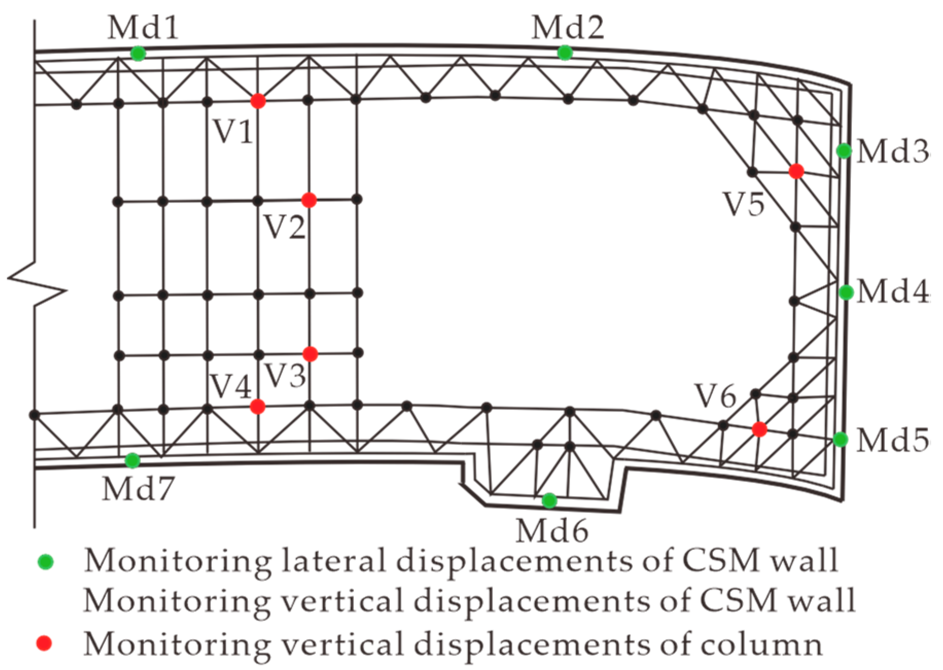
2.2. Monitoring Program

The monitoring items of this project mainly include the lateral/vertical displacement of the CSM wall and the vertical displacement of the top of the column post. The area shown in Figure 2 is arranged with seven lateral/vertical displacement measurement control points of the CSM wall (Md) and six vertical displacement measurement control points of column (V). The monitoring frequency was determined according to the actual situation of the project before the excavation of the pit, and the monitoring frequency was adjusted according to the change in data during the construction process.

3. Model Building

3.1. Basic Assumptions

Given the complexities involved in the construction process and the various environmental factors affecting foundation pits, it is necessary to make certain assumptions and simplifications when establishing a numerical model for analysis and calculation purposes. This study is based on the following basic assumptions [34,35,36]:
  • It is assumed that the soil within the influence range of the foundation pit behaves as an elastic-plastic body, meaning that it is uniformly distributed, continuous, and isotropic. To model the constitutive behavior of the soil, the Modified Mohr–Coulomb constitutive model was adopted. The ground wall, uplift pile, and internal support system are all equivalent to a beam system, whereas the pressure bar between walls is equivalent to a truss system. A linear elastic beam or truss model was utilized for all of these structural components.
  • The calculation of the initial ground stress only considers the gravity stress of soil in each layer while neglecting the influence of tectonic stress and other stresses between the rock and soil bodies.
  • Good foundation pit drainage is maintained during construction, regardless of any deformation in the retaining structure due to groundwater or soil consolidation.
  • The time effect of the soil deformation and the effect of the construction of the support structure on the soil are not considered. All the support is timely and only considers the deformation of the foundation pit retaining structure due to the spatial effect of soil excavation.
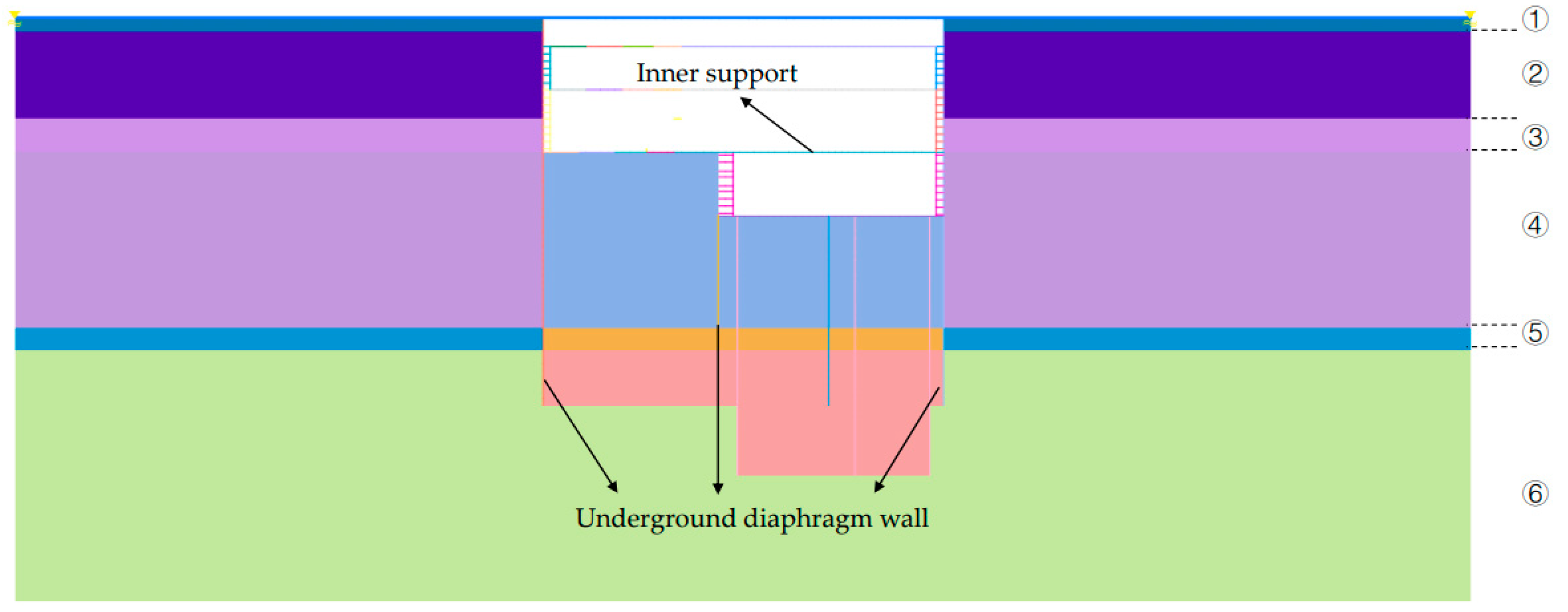
In this paper, the construction of a multi-span foundation pit excavation support structure system was simulated utilizing Midas GTS NX finite element calculation software to explore the effects of embedment depth of different supporting structures and internal support span on lateral displacement, vertical displacement, internal support force, and bending moment. Subsequently, this study used finite element analysis to predict critical points in the system and develop preventative measures that can minimize risks and enhance the construction process’s safety and efficiency.

3.2. Model Overview

3.2.1. Constitutive Model

This study adopted the Modified Mohr–Coulomb constitutive model (MMC) as the basic model and established a two-dimensional finite element model based on the project’s geological conditions and the surrounding environment. The Modified Mohr–Coulomb model is an extension of the Mohr–Coulomb model and is commonly used for silty or sandy soils. It is a composite material model that combines nonlinear elastic and plastic models to describe the soil behavior [37,38,39]. The parameters of each soil layer in the foundation pit are shown in Table 1.

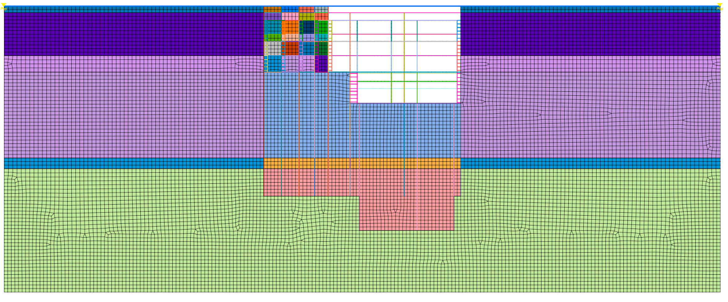
3.2.2. GTS NX Models

The wireframe of the model was created using CAD, and a two-dimensional model was established using MIDAS/GTS to simulate the excavation and construction process of the foundation pit. The 2D unit simulated the soil of each layer, and the inner support, uplift pile, column pile, and structural plate were simulated using a 1D linear elastic beam unit model. The pressure bar between walls was simulated by a 1D elastic truss element line model, comprising a total of 16,454 2D elements and 15,283 nodes. In this regard, the mesh size of the soil layer elements is determined based on the thickness of each respective soil layer, averaging at approximately 1.0 m × 1.0 m. Table 2 displays the structural unit material parameters used in the model, and Figure 1 illustrates the model.
In accordance with varying CSM wall embedment depths and excavation spans, this paper delineates ten distinct working conditions. These conditions were listed from ① to ⑩ as follows: ① short ground wall equal length single span, ② short ground wall equal length two spans, ③ short ground wall equal length three spans, ④ short ground wall equal length four spans, ⑤ short ground wall equal length five spans, ⑥ long ground wall equal length single span, ⑦ long ground wall equal length two spans, ⑧ long ground wall equal length three spans, ⑨ long ground wall equal length four spans, and ⑩ long ground wall equal length five spans.
The CSM wall was set 0.1 m away from the supporting structure, with an embedded depth of 18.5 m for working conditions ①, ②, ③, ④, and ⑤ and 27.0 m for working conditions ⑥, ⑦, ⑧, ⑨, and ⑩. The span of pit excavations is 37.00 m under working conditions ① and ⑥; 40.80 m under working conditions ② and ⑦; 45.15 m under working conditions ③ and ⑧; 50.07 m under working conditions ④ and ⑨; and 55.00 m under working conditions ⑤ and ⑩. Working conditions 1, 4, and 9 are selected as typical representatives, and the schematic diagram is shown in Figure 3.

3.2.3. Boundary Constraints

The model employed the surrounding constraint as its primary constraint. It did not consider the impact of soil stress changes during pit excavation, nor did it assume any initial displacement of the model soil. The model solely focused on the effects of gravity loads on the soil and ignored other loading factors. As a result, the pit model analyzed only accounts for gravity loads. The boundary constraints are shown in Figure 4., and the size parameters of the model structure unit are shown in Table 2.
The study focused on assessing the impact of multi-span excavation on the stability and deformation of the enclosure structure. Therefore, the impact of the surrounding structures and underground pipeline facilities on the supporting structure was not considered for the time being.

3.3. Process Simulation

The construction phase analysis method and the activation/passivation technique of finite element mesh groups were utilized to simulate the actual construction process by distributing the activation and passivation of corresponding cells for each construction phase dynamically. During the simulation, the excavation and support method was used. Initially, all soil cells were activated, followed by simulating the excavation process while constructing the support structure. By employing the “passivation” function in the finite element software, the excavation process of the foundation pit was simulated according to the actual excavation sequence, whereas the “activation” function was used to simulate the construction of the support structure. For instance, Figure 5 illustrates the simulation process for the 12th process, named “New negative first floor” in Condition 1. It is crucial that the overall simulation process follows the site construction sequence as closely as possible, enabling it to provide practical and feasible information guiding the site operation and construction.
The specific working conditions are classified into ten types based on the excavation width and the arrangement of the ground connection wall. For instance, Condition 1, which involves the excavation of a foundation pit with equal length and single span, shows the specific construction stages in Table 3.

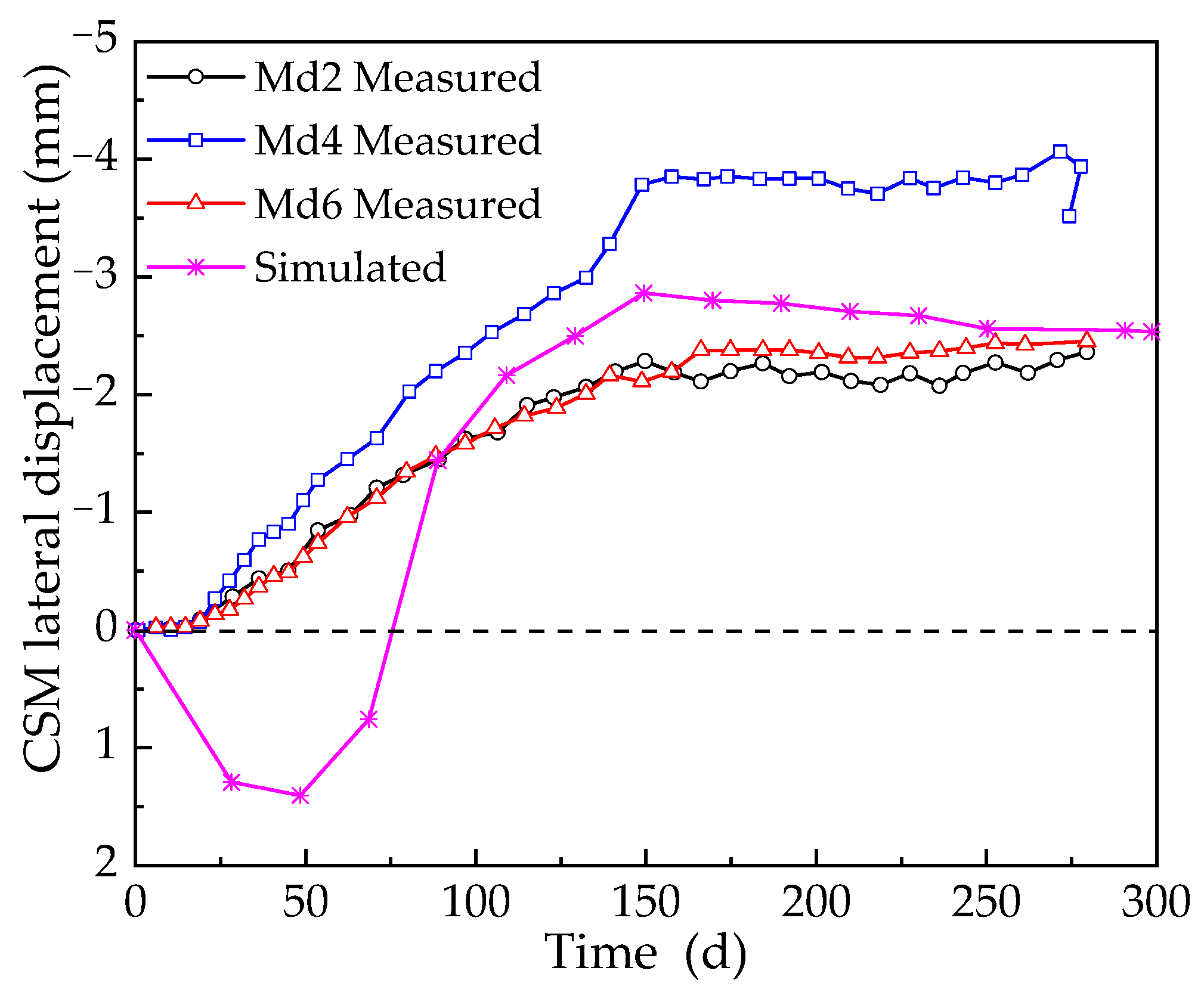
3.4. Validation of Model Results

In order to ensure the accuracy and reliability of the numerical finite element simulation calculation results, the pit CSM wall lateral displacement monitoring data were extracted and compared with the Midas GTS NX simulation results, and the results are shown in Figure 6. The displacement of the CSM wall is indicated as “+” and “−” for the direction towards and outside the pit, respectively. As can be seen in Figure 6, the lateral displacement of the top of the CSM wall developed continuously as the excavation depth increased during excavation of the foundation pit. From the pit excavation to the completion stage, the displacement of the top of the CSM wall towards the outside of the pit gradually increases and tends to be stable, and the maximum displacement is −4.06 mm. The simulation results are slightly larger than the measured data, and the maximum lateral displacements of the CSM in the single-span pits have a smaller average error of 21% and 14% with respect to Md 2 and Md 6, respectively. Simulation values agree well with monitoring data, and it is reasonable to assume that finite element model results can basically accurately reflect CSM wall displacement and deformation law and the changing law of other influences.
Excessive lateral displacement can seriously compromise the safety of the project as the displacement of the top of the CSM wall directly affects the deformation of the surrounding ground outside the pit. According to the study of Zhang et al. [39] on the limit displacement of the retaining wall under the limit equilibrium state, for the clay layer, the maximum lateral displacement limit of the retaining wall towards the inside of the pit is basically in the range of 0.002–0.005 H (H is the height of the rigid support structure above the ground), and the maximum lateral displacement limit of the retaining wall towards the ground is about 10 times of the maximum lateral displacement of the retaining wall towards the inside of the pit [40]. The excavation depth of this pit is H = 27.2 m, and the maximum lateral displacement towards the soil is 4.06 mm, which is much smaller than the lower limit of allowable displacement.

4. Analysis of Calculation Results

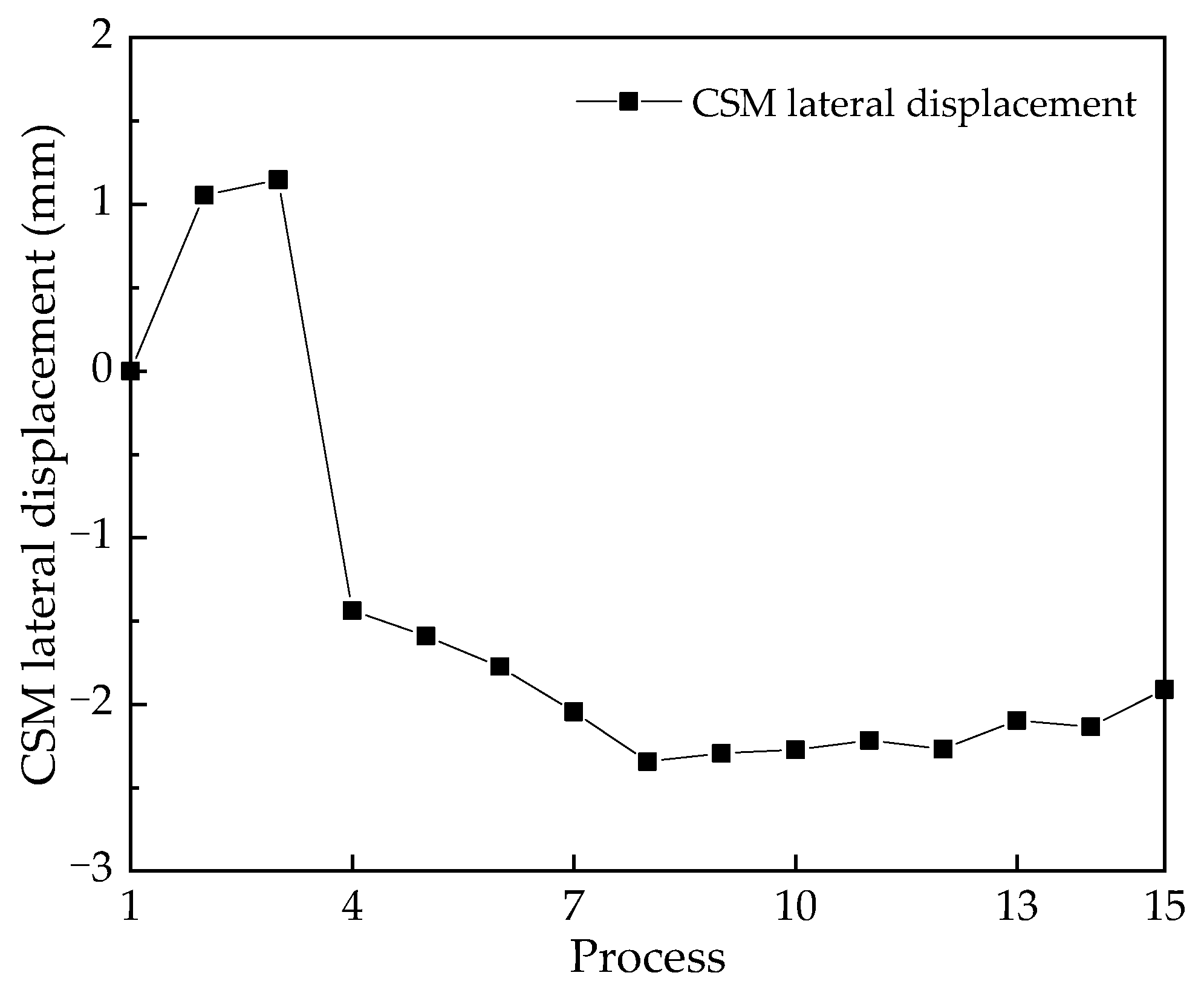
4.1. CSM Wall Lateral Displacement

In this study, the maximum lateral displacement of CSM wall unit nodes in fifteen different processes with varying embedment depths for working conditions ① was analyzed, and this working condition was used as an example to carry out the analysis. On this basis, the lateral displacements of the CSM wall support structure during construction were simulated, as shown in Figure 7.
After conducting numerical simulations of ten different working conditions and comparing the results using Figure 8, the conclusions are as follows:
The embedment depth of the CSM wall plays a vital role in the pit enclosure design process. Several factors, such as construction difficulty, pit construction cost, and groundwater infiltration during precipitation excavation, make it a crucial consideration for actual projects. The maximum lateral displacement at a depth of 27.0 m is about 6.8% larger than that at a depth of 18.5 m. The reason is that the smaller embedment depth does not have enough stiffness to resist the lateral earth pressure, and the tendency of deflection in the pit is intensified, resulting in the convergence of the top of the wall towards the inner side of the pit and the small lateral displacement.
When the excavation span is between one and three spans, the lateral displacement of the CSM wall in the outward direction of the pit increases as the excavation span increases. When the pit span is between three and five spans, the increase in the number of pit spans increases the stiffness of the CSM wall support, which stabilizes the lateral displacement of the CSM wall. Take working condition ①–⑤ as an example; the maximum lateral displacement value of the CSM wall increased by 21.14% over the minimum value.

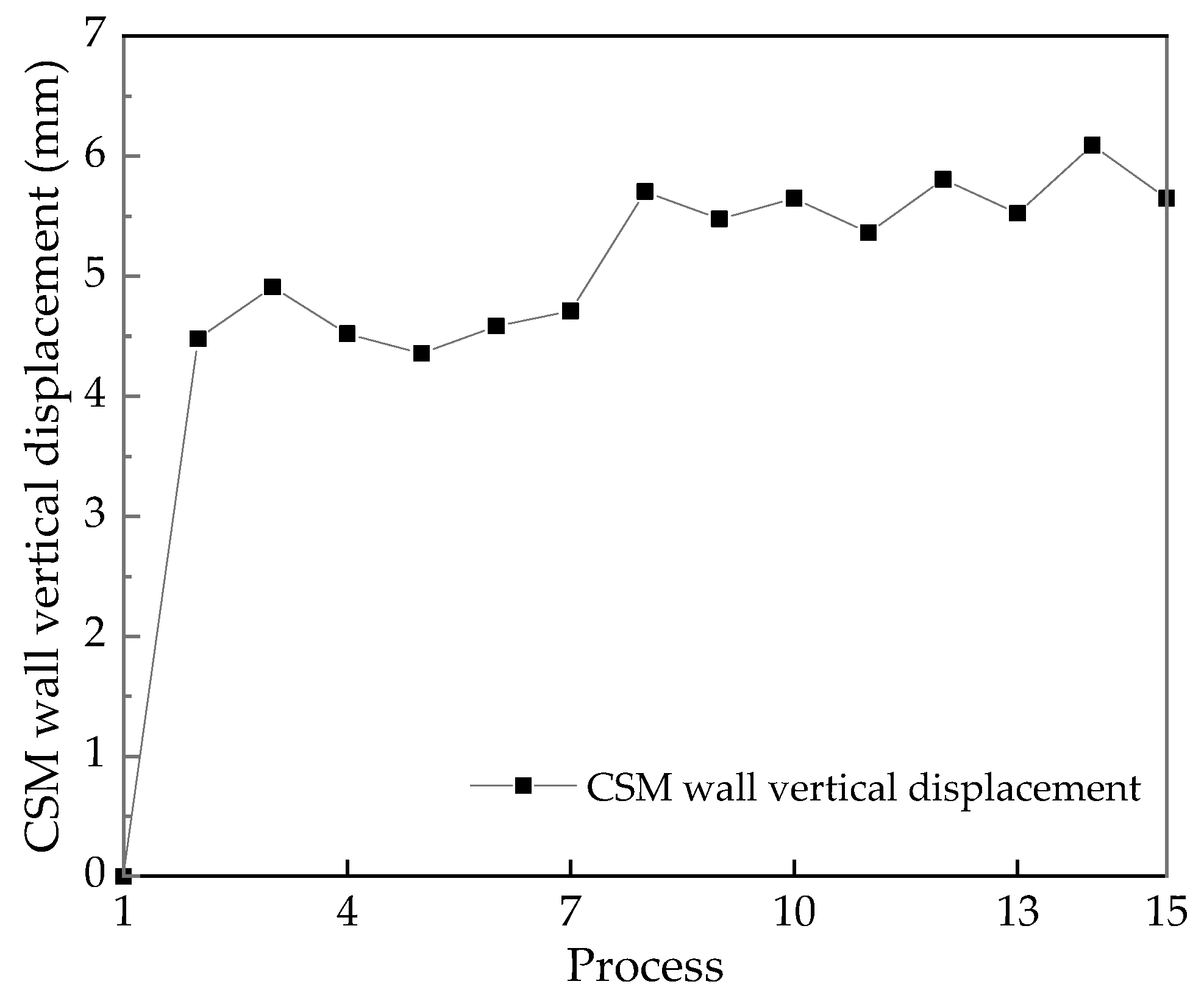
4.2. CSM Wall Vertical Displacement

To analyze the maximum vertical displacement of CSM wall unit nodes for various embedment depths under working conditions ①, we selected fifteen processes and calculated the simulated values of the vertical upward and downward displacement of the CSM wall support structure. The results are shown in Figure 9. The displacement of CSM wall “+” and “−” represent vertical downward and upward displacement, respectively.
The numerical simulations of ten different working conditions were conducted, and after a comparison based on Figure 10, drew the following conclusions.
After thorough numerical simulations, it was observed that the settlement value of the CSM wall is 6.09 mm at an embedment depth of 18.50 m for single-span pit excavation. Similarly, the settlement value is 5.90 mm at an embedment depth of 27.00 m. It is noteworthy that the vertical displacements of the CSM wall are controlled within a certain range as the depth of burial of the CSM wall increases.
In actual projects, the different spans of the excavated pit have a significant effect on both the supporting structure and the CSM wall. It is observed that the maximum vertical displacement of the CSM wall decreases and then increases significantly with the increase in the number of spans of the excavated pit and the maximum and minimum vertical displacements are found in two-span and four-span, respectively, with a difference of 1.02 mm.
Specifically, the vertical displacement of the CSM wall tends to decrease as the excavated pit is between one and two spans, increase as it is between two and four spans, and decrease again as it is between four and five spans. Additionally, the vertical displacement of CSM walls tends to increase with the length of the excavated soil span when the excavated pit is between one and four spans and decreases with the length of the span when the excavated pit is between four and five spans. Take working condition ①–⑤ as an example; the maximum vertical displacement value of the CSM wall increased by 16.89% over the minimum value.

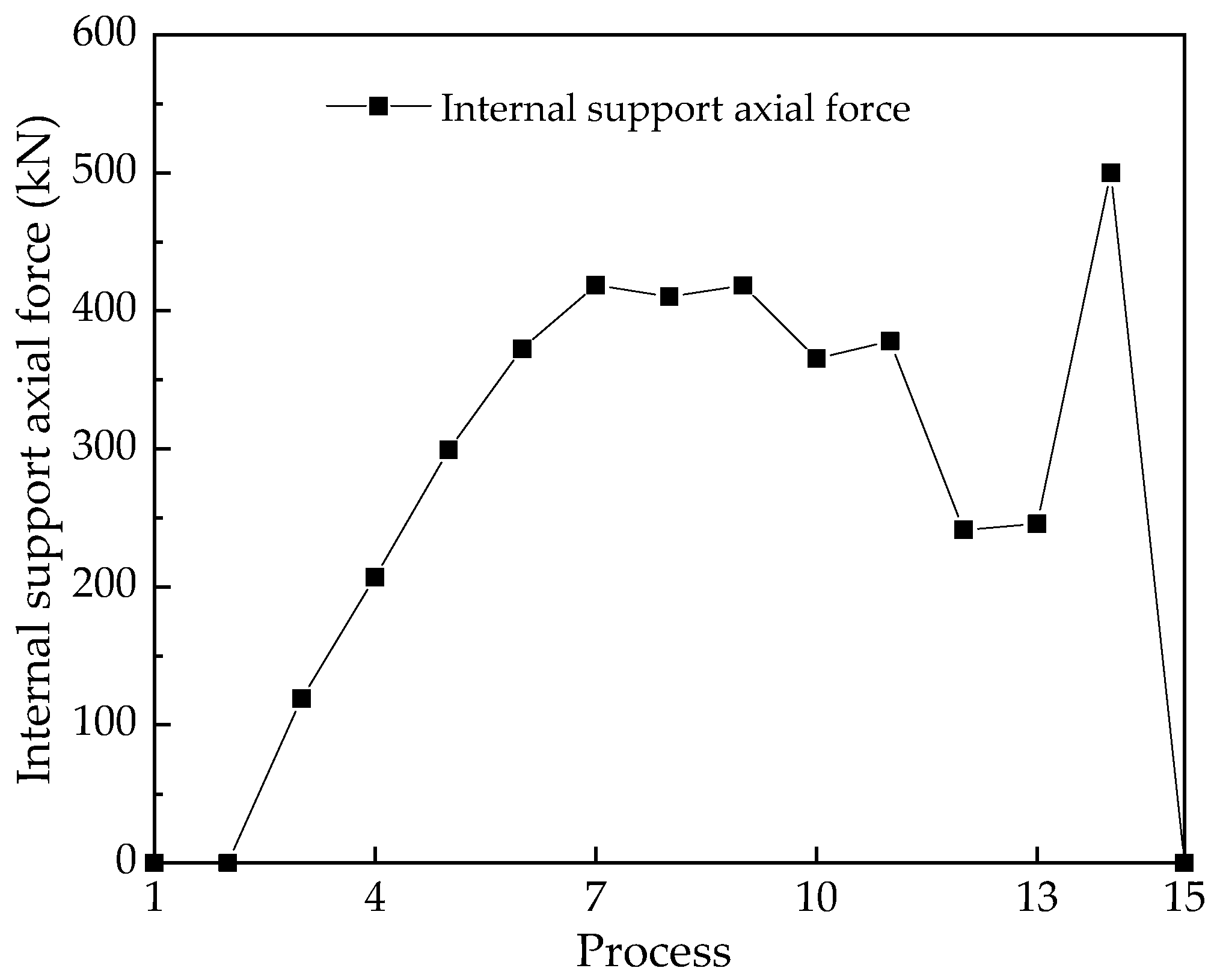
4.3. Internal Support Shaft Force

The numerical analysis of different embedment depths of the CSM wall was conducted in fifteen processes, using the axial forces in the X-direction of the steel supports’ unit nodes for each working condition. The simulated values of the axial forces of the steel supports were calculated and presented in Figure 11.
Based on the numerical simulations of ten working conditions and lateral comparisons, it can be concluded from Figure 12 that the axial forces applied to the steel supports are all compressive stresses.
Regarding the effect of the embedment depth of the CSM wall on the internal force of the CSM wall and steel bracing in the actual project, for a single-span pit, the steel bracing axial force is 500.01 kN at an embedment depth of 18.50 m and 529.56 kN at an embedment depth of 27.00 m. In the range of one and two spans, the axial force of the steel support increases with the increase in the embedment depth of the CSM wall. However, in the range of two to five spans, there is no clear change in the axial force of the steel support with increasing embedment depth of the CSM wall.
When the excavated pit is between one and two spans, there is an increasing trend in the steel support axial force with the length of the span. For pits between two and three spans, however, the trend is reversed, with a smaller axial force observed for longer spans. Finally, when the pit spans between three and five spans, the trend of increasing axial force with longer spans is again observed. Take working condition ①–⑤ as an example; the maximum value of the axial force of steel support increased by 7.26% over the minimum value.
The formula provided in JGJ120-2012 (4.5) [41] is used to calculate the internal support axial force. It is important to note that the design of the support needs to consider several factors, including soil type, excavation depth, and groundwater level. The regulations provide specifications for pit support design, installation, monitoring, and maintenance to ensure safety and stability during construction.
N z = N zl + i = 1 n 0.1 N i
where Nz is the internal support axial force, Nzl represents the set value of the axial force generated by the lateral inner support, Ni is the design value of the maximum axial force of the i layer, and n is the number of spans.
According to the construction procedures outlined in the QJ/STEC 001-2015 [42] guidelines for steel support systems in foundation pits, the allowable axial forces for the support system can be determined using Schedule 1 and Schedule 4, along with Equation (1). The calculations indicate that for a single-span foundation pit, the maximum allowable axial force is 1200 kN, and the steel support axial force is 529.56 kN, which satisfies the requirement [41]. The maximum allowable axial force for a two-span foundation pit is 1100 kN, and the corresponding steel support axial force is 537.73 kN, meeting the requirements. Similarly, for a three-span foundation pit, the maximum allowable axial force is 1000 kN, and the steel support axial force is 526.84 kN, satisfying the requirements. In the case of a four-span foundation pit, the maximum allowable axial force is 900 kN, and the steel support axial force necessary is 527.72 kN, meeting the requirement. For a foundation pit with five spans, the maximum allowable axial force is 800 kN, and the corresponding steel support axial force is 532.38 kN, which also meets the criteria. It is worth noting that the calculated internal support axial force depends on factors such as excavation depth, soil type, and groundwater level. Regular monitoring is necessary to ensure the stability of the support system and its ability to handle anticipated loads.

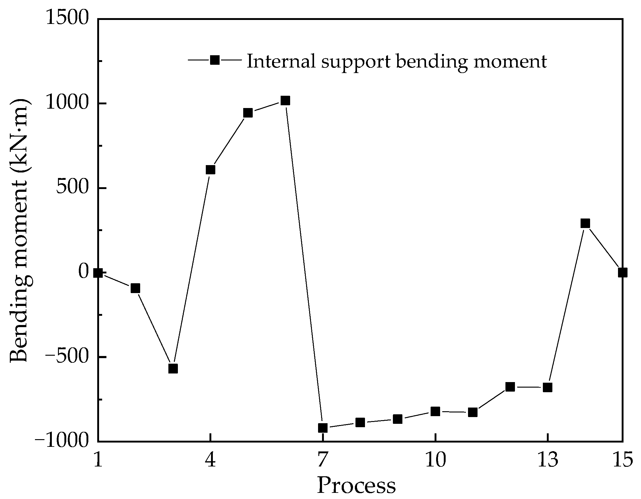
4.4. Bending Moment of Internal Support

Bending moment analyses of steel-braced unit nodes were carried out for 15 different processes in Table 1 for different burial depths of the CSM wall under working conditions ①. Two bending moments were selected for numerical analysis, and the simulated values of the process steel support axial force are presented in Figure 13. The moment of the external force on the beam on the left side of the section towards the center of the section is a positive bending moment when turning clockwise and a negative bending moment when turning anticlockwise. As can be seen from the figure, the bending moment of the steel column removal stage is generally larger than that of the steel column construction stage. When the last steel support is installed, although the bending moment value of the steel support is reduced, the direction is deflected, which easily causes the instability of the steel support.
In the excavation process, the bending moments inside the steel struts of different processes are different, but there is a maximum bending moment in all five steel struts of all processes, and if this maximum bending moment is smaller than the maximum permissible bending moment, the steel struts will meet the engineering requirements. Take condition 1 as an example; we can obtain the bending moment cloud diagram of the process 8 steel strut, as shown in Figure 14. The maximum bending moment is considered in the calculation.
Upon conducting numerical simulation and lateral comparison for ten working conditions, it was observed that the maximum bending moment exerted on the steel support occurs in the Y-axis direction of the unit coordinate system. By analyzing Figure 15, several conclusions can be made.
In the single-span foundation pit, the burial depth of the concrete wall has no significant effect on the internal forces in the concrete wall and steel support system when the burial depth reaches a certain level. The bending moment of the steel support reached 1025.80 kN·m at a burial depth of 18.50 m and 1034.15 kN·m at a burial depth of 27.00 m, with an increase in bending moment of only 0.8%.
The effect of the excavated soil span on the bending moment of the pit steel was not significant. For pits between one and two spans, an increase in the span tends to result in a larger steel support moment. However, for pits between two and five spans, an increase in the span tends to lead to a smaller steel support moment.
Although the bending moment inside the steel support varies greatly in different processes during excavation, there is a maximum bending moment in the five steel supports of all processes, and if this maximum bending moment is smaller than the maximum allowable bending moment, the steel support meets the engineering requirements.
According to Section 4.5 of the Technical Specification for Retaining and Protection of Building Foundation Excavations (JGJ120-2012) [41], the design value of the vertical load of the support system should account for the self-weight of the structure and the construction load. The bending moment of the member can be calculated based on the multi-span continuous beam, and the calculated span is taken from the center distance of the adjacent column.
As per Schedule 1 and Schedule 4 of the QJ/STEC 001-2015 Construction Regulations for Steel Bracing System for Pit Works [42], the maximum allowable bending moment and the corresponding maximum bending moment values for the steel bracing or steel support were calculated for pits of different spans. Specifically, for a single-span pit, the maximum allowable bending moment is 1600 kN·m, and the maximum bending moment of the steel bracing is 1034.15 kN·m, meeting the requirements. For a two-span pit, the maximum allowable bending moment is 1400 kN·m, and the maximum bending moment of the steel bracing meets the requirements. For a three-span pit, the maximum allowable bending moment is 1300 kN·m, and the maximum bending moment of the steel support is 1027.42 kN·m, meeting the requirements. For a four-span pit, the maximum allowable bending moment is 1200 kN·m, and the maximum bending moment of the steel support is 1025.64 kN·m, meeting the requirements. Lastly, for a five-span pit, the maximum allowable bending moment is 1100 kN·m, and the maximum bending moment of the steel support is 1034.15 kN·m or 1023.47 kN·m, which meets the requirements.

5. Conclusions

The GTS NX finite element simulation software was employed, taking the foundation pit project in eastern China as a reference case. The objective was to assess the impact of CSM walls and internal support systems and provide valuable insights for optimizing the design of similar pit excavation projects in the future. This research compared ten different working conditions to determine the displacements of the CSM wall and the forces exerted on the support system during the foundation excavation process. Two factors were investigated in this study, namely the pit span and CSM wall burial depth. The effect of different pit spans on the behavior and performance of the CSM wall system was investigated for single, two, three, four, and five span pits. The conclusions are as follows.
  • Measured field data indicate that the maximum lateral displacement of the side wall of the foundation pit increases gradually with the excavation of the foundation pit, and the lateral displacement tends to be stable gradually at the later stage of excavation. The apex of the CSM wall exhibits a maximum lateral displacement toward the ground of merely 4.06 mm, which is less than the lower limit of allowable displacement. This outcome substantiates the efficacy of this technology in delivering robust foundation pit support. Moreover, the simulation results underscore their precision and reliability, as evidenced by the commendable concurrence between on-site measurements and the numerical data.
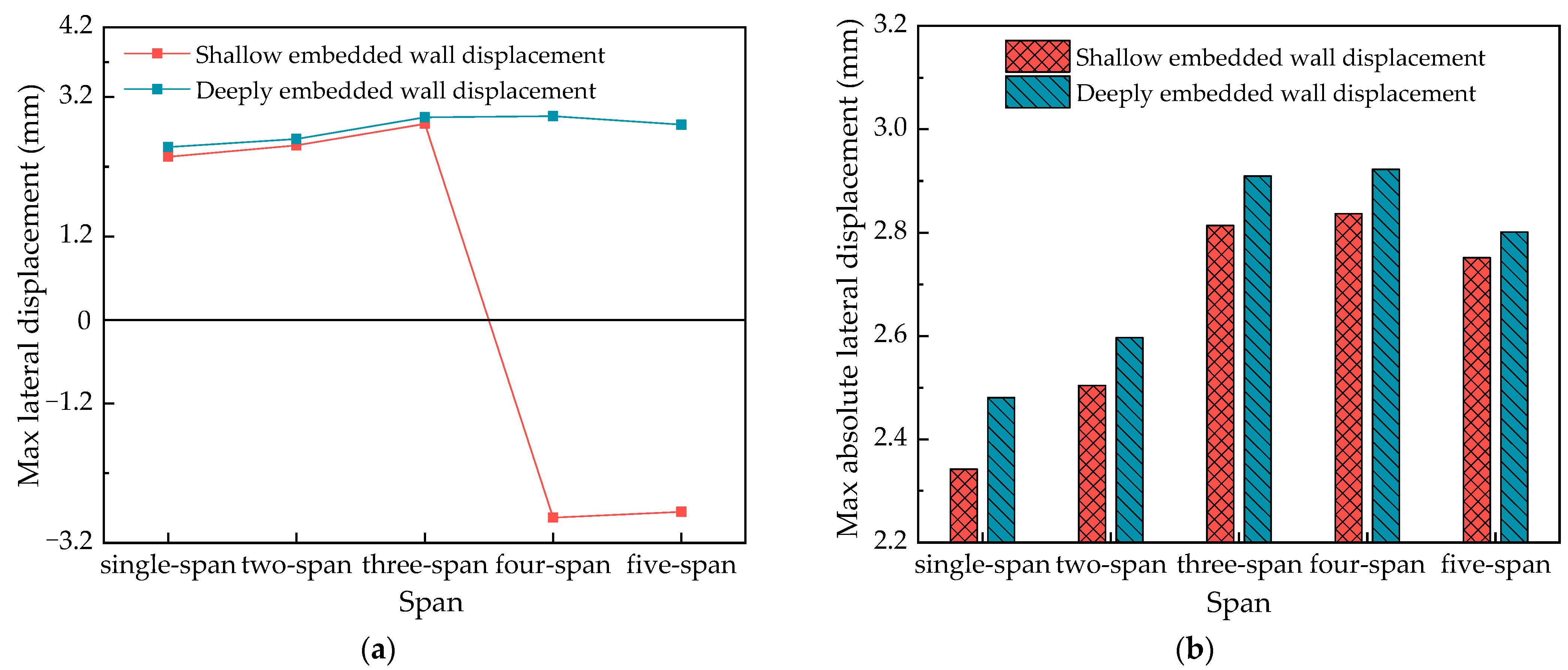
  • Once embedment depth was reached, further increases in embedment depth may be helpful in improving cavity containment, but their effectiveness is limited. As the embedment depth increases, the internal support moment and lateral displacement of the wall increase slightly. To achieve optimal design and ensure safety, the depth of the CSM wall embedment should be fully considered during the design stage of the foundation pit.
  • As the span of the excavation increases, the pressure of the soil on the CSM wall increases, the axial force of the steel column increases continuously, and the values of the lateral displacement of the CSM wall, the vertical displacement, and the bending moments of the steel column first increase and then decrease. The most unfavorable value is in this area of the pit span, so it should be fully considered in the pit design.

Author Contributions

Conceptualization, G.-Q.C.; methodology G.-Q.C. and J.W.; Numerical simulation, J.W., Y.-P.S. and D.-J.L.; data curation, J.W., Y.-P.S. and D.-J.L.; writing—original draft preparation, J.W., Y.-P.S., D.-J.L. and Y.-L.S.; writing—review and editing, Y.-L.S. and H.-X.W.; supervision, G.-Q.C. and H.-X.W.; funding acquisition, G.-Q.C. All authors have read and agreed to the published version of the manuscript.

Funding

This research was financially supported by the Fundamental Research Funds for the Central Universities (2023JBZD004), the National Natural Science Foundation of China (U2034204, 52078031), and the Development Fund of Tunnel and Underground Engineering Research Center of Jiangsu Province (2021-SDJJ-04).

Institutional Review Board Statement

Not applicable.

Informed Consent Statement

Not applicable.

Data Availability Statement

Not applicable.

Conflicts of Interest

The authors declare no conflict of interest.

References

  1. Cano-Hurtado, J.J.; Canto-Perello, J. Sustainable development of urban underground space for utilities. Tunn. Undergr. Space Technol. 1999, 14, 335–340. [Google Scholar] [CrossRef]
  2. Yu, P.; Liu, H.H.; Wang, Z.S.; Fu, J.N.; Zhang, H.; Wang, J.; Yang, Q. Development of urban underground space in coastal cities in China: A review. Deep Undergr. Sci. Eng. 2023, 2, 148–172. [Google Scholar] [CrossRef]
  3. Zeng, F.Y.; Li, M.G.; Chen, J.J.; Wang, J.H. Development and application of a system for dynamic and synchronous analysis of both monitor data and construction information in foundation Pit groups. J. Shanghai Jiao Tong Univ. 2017, 51, 269–276. (In Chinese) [Google Scholar] [CrossRef]
  4. Li, J.P.; Chen, H.H.; Li, L.; Ma, J.S. Observation on depth and spatial effects of deep excavation in soft clay. China J. Highw. Transp. 2018, 31, 208–218. (In Chinese) [Google Scholar] [CrossRef]
  5. Bobylev, N.; Sterling, R. Urban underground space: A growing imperative. Perspectives and current research in planning and design for underground space use. Tunn. Undergr. Space Technol. Inc. Trenchless Technol. Res. 2016, 55, 1–4. [Google Scholar] [CrossRef]
  6. Hunt, D.V.L.; Makana, L.O.; Jefferson, I.; Rogers, C.D.F. Liveable cities and urban underground space. Tunn. Undergr. Space Technol. 2016, 55, 8–20. [Google Scholar] [CrossRef]
  7. Gerressen, F.W.; Vohs, T. CSM-Cutter Soil Mixing-Worldwide Experiences of a young soil mixing method. Grouting Deep Mix. 2012, 2012, 281–290. [Google Scholar] [CrossRef]
  8. Bellato, D.; Marzano, I.P.; Simonini, P. Microstructural Analyses of a Stabilized Sand by a Deep-Mixing Method. J. Geotech. Geoenvironmental Eng. 2020, 146, 04020032. [Google Scholar] [CrossRef]
  9. Cheng, H.Z.; Li, W.T.; Chen, R.P.; Yi, Y.L. Workability study of sand-bentonite-cement mixtures for construction of two-phase cut-off wall. Constr. Build. Mater. 2022, 345, 128058. [Google Scholar] [CrossRef]
  10. Nishanthan, R.; Liyanapathirana, D.S.; Leo, C.J. Deep cement mixed walls with steel Inclusions for excavation support. Geotech. Geol. Eng. 2018, 36, 3375–3389. [Google Scholar] [CrossRef]
  11. Gomes, C.A.; Tinoco, J.; Pinto, A.; Tomásio, R. An anchored retaining wall in CSM. In Proceedings of the 18th International Conference On Soil Mechanics And Geotechnical Engineering, Paris, France, 2–6 September 2013; pp. 1–4. Available online: https://www.researchgate.net/publication/256445919 (accessed on 15 July 2023).
  12. Leach, C.; Gerressen, F.W. First known application of Cutter Soil Mixing for support of a Heritage Building. IFCEE 2015, 2015, 554–568. [Google Scholar] [CrossRef]
  13. Lindquist, D.; Upsall, B.; Horvitz, G. Cutter Soil Mixing excavation and shoring in Seattle’s pioneer square district. In Proceedings of the Earth Retention Conference 3, Washington, DC, USA, 1–4 August 2010; pp. 303–310. [Google Scholar]
  14. Arnold, M.; Beckhaus, K.; Wiedenmann, U. Cut-off wall construction using cutter soil mixing: A case study. Geotechnik 2015, 34, 11–21. [Google Scholar] [CrossRef]
  15. Capelo, A.; Correia, A.G.; Ramos, L.F.; Pinto, A.; Rui, T. Modeling and monitoring of an excavation support using CSM. Int. Conf. Grouting Deep Mix. 2012, 2012, 243–250. [Google Scholar] [CrossRef]
  16. Pinto, A.; Tomásio, R.; Pita, X.; Pereira, A.; Peixoto, A. Cutter Soil Mixing solutions in portugal. Grouting Deep Mix. 2012, 2012, 316–325. [Google Scholar] [CrossRef]
  17. Liao, S.M.; Wei, S.F.; Tan, Y.; Liu, J.X. Measured analysis of deformation behavior of large-scale deep foundation pit in Suzhou area. Chin. J. Geotech. Eng. 2015, 37, 458–469. (In Chinese) [Google Scholar] [CrossRef]
  18. Wang, Z.; Guo, B.L.; Wei, G.; Hu, C.B.; Zhang, L.S. Simplified deformation analyses of a single pile subjected to different deformation modes of the pit enclosure structure. Int. J. Geomech. 2023, 23, 04023014. [Google Scholar] [CrossRef]
  19. Han, M.; Li, Z.; Mei, G.X.; Bao, X.H.; Jia, J.Q.; Liu, L.L.; Li, Y.Y. Characteristics of subway excavation in soft soil and protective effects of partition wall on the historical building and pile foundation building. Bull. Eng. Geol. Environ. 2022, 81, 307. [Google Scholar] [CrossRef]
  20. Li, Y.J.; Feng, Z.J.; Zhu, Y.P. Monitoring and numerical simulation analysis of support structures of deep foundation pit in special red sandstone stratum in Lanzhou. Chin. J. Geotech. Eng. 2022, 44, 236–240. (In Chinese) [Google Scholar] [CrossRef]
  21. Li, X.J.; Zeng, K.H.; Bai, D.Z.; Chen, F.L.; Ju, H.Y.; Xu, M.Q. Application of CSM waterproof curtain in foundation pit engineering of deep saturated sand layer. IOP Conf. Ser. Earth Environ. Sci. 2020, 455, 012048. [Google Scholar] [CrossRef]
  22. Rabbani, P.; Lajevardi, S.H.; Tolooiyan, A.; Daghigh, Y.; Falah, M. Effect of Cutter Soil Mixing (CSM) method and curing pressures on the tensile strength of a treated soft clay. Heliyon 2019, 5, e02186. [Google Scholar] [CrossRef]
  23. Russell, A.R.; Chapman, M.; Teh, S.H.; Wiedmann, T. Cost and embodied carbon reductions in cutter soil mix walls through fibre reinforcement. Geosynth. Int. 2017, 24, 280–292. [Google Scholar] [CrossRef]
  24. Cao, S.Y.; Song, S.; Qi, X.L. Research on deep foundation pit excavation based on numerical simulation. J. Phys. Conf. Ser. 2021, 1885, 022051. [Google Scholar] [CrossRef]
  25. Wang, J.F.; Xiang, H.W.; Yan, J.G. Numerical simulation of steel sheet pile support structures in foundation pit excavation. Int. J. Geomech. 2019, 19, 05019002. [Google Scholar] [CrossRef]
  26. Castaldo, P.; Jalayer, F.; Palazzo, B. Probabilistic assessment of groundwater leakage in diaphragm wall joints for deep excavations. Tunn. Undergr. Space Technol. 2018, 71, 531–543. [Google Scholar] [CrossRef]
  27. Ye, S.H.; Ding, S.H.; Gong, X.N.; Gao, S.; Chen, C.L. Monitoring and numerical simulation of deep foundation pit of a subway station in Lanzhou. Chin. J. Geotech. Eng. 2018, 40, 177–182. (In Chinese) [Google Scholar]
  28. Ye, S.H.; Zhao, Z.; Wang, D. Deformation analysis and safety assessment of existing metro tunnels affected by excavation of a foundation pit. Undergr. Space 2021, 6, 421–431. [Google Scholar] [CrossRef]
  29. Ramm, H.; Reul, O.; Ruiken, A.; Kissel, W.; Toker, E. Hochhaus omniturm–Baugrube und Gründung unter komplexen innerstädtischen Randbedingungen. Bautechnik 2020, 97, 656–663. [Google Scholar] [CrossRef]
  30. Zhang, C. Control force characteristics of different control strategies for the wind-excited 76-story benchmark building structure. Adv. Struct. Eng. 2016, 15, 423–434. [Google Scholar] [CrossRef]
  31. Lin, P.; Liu, P.; Ankit, G.; Singh, Y.J. Deformation monitoring analysis and numerical simulation in a deep foundation pit. Soil Mech. Found. Eng. 2021, 58, 56–62. [Google Scholar] [CrossRef]
  32. Qian, Q.H.; Lin, P. Safety risk management of underground engineering in China: Progress, challenges and strategies. J. Rock Mech. Geotech. Eng. 2016, 8, 423–442. [Google Scholar] [CrossRef]
  33. Theunissen, W.; Fraser, O.D. Three-dimensional numerical modeling of a propped cutter soil mix retention system in sand. Int. J. Geoengin. Case Hist. 2021, 6, 115–151. [Google Scholar] [CrossRef]
  34. Parmantier, D.M.; Stow, R.F.; Byrne, R.J. Case study: Cement-bentonite pre-trenching and cutter soil mixing (CSM) for temporary shoring and groundwater cutoff. In Contemporary Topics in Ground Modification, Problem Soils, and Geo-Support; ASCE Library: Reston, VA, USA, 2009; pp. 153–160. [Google Scholar]
  35. Bose, S.K.; Som, N.N. Parametric study of a braced cut by finite element method. Comput. Geotech. 1998, 22, 91–107. [Google Scholar] [CrossRef]
  36. Borja, R.I.; Amies, A.P. Multiaxial cyclic plasticity model for clays. J. Geotech. Eng. 1994, 120, 1051–1070. [Google Scholar] [CrossRef]
  37. Feng, Z.Y.; Xu, Q.; Xu, X.Y.; Tang, Q.; Li, X.D.; Liao, X. Deformation characteristics of soil layers and diaphragm walls during deep foundation pit excavation: Simulation verification and parameter analysis. Symmetry 2022, 14, 254. [Google Scholar] [CrossRef]
  38. Ezzat, M.; Zaghloul, Y.; Sorour, T.; Hefny, A.; Eid, M. Numerical simulation of axially loaded to failure large diameter bored pile. Int. J. Geotech. Geol. Eng. 2019, 13, 283–297. [Google Scholar]
  39. Zhang, C.G.; Shan, Y.P.; Gao, B.X. A new mathematical fitting formulation of earth pressure considering the displacement of retaining walls. Chin. J. Rock Mech. Eng. 2021, 40, 2124–2135. (In Chinese) [Google Scholar] [CrossRef]
  40. Ni, P.P.; Mangalathu, S.; Song, L.H.; Mei, G.X.; Zhao, Y.L. Displacement-dependent lateral earth pressure models. J. Eng. Mech. 2018, 144, 04018032. [Google Scholar] [CrossRef]
  41. JGJ 120-2012; Technical Specification for Retaining and Protection of Building Foundation Excavations. China Architecture Publishing & Medi Co., Ltd.: Beijing, China, 2012.
  42. QJ/STEC 001-2015; Construction Regulations for Steel Bracing System for Pit Works. Shanghai Tunnel Engineering Co., Ltd.: Shanghai, China, 2015.
Figure 1. Schematic diagram of the main structure of the pit.
Sustainability 15 14745 g001
Figure 2. Monitoring layout plan.
Sustainability 15 14745 g002
Figure 3. (a) Construction model under Condition 1; (b) Construction model under Condition 4; (c) Construction model under Condition 9.
Sustainability 15 14745 g003
Figure 4. Two-dimensional multi-span foundation pit model.
Sustainability 15 14745 g004
Figure 5. Equal-length cross-foundation pit process 12.
Sustainability 15 14745 g005
Figure 6. Comparison of numerical simulation results with measured data.
Sustainability 15 14745 g006
Figure 7. Maximum lateral displacement of CSM wall in equal-length single-span foundation pit.
Sustainability 15 14745 g007
Figure 8. (a) Max lateral displacement values for CSM walls with different embedment depths; (b) absolute values of max lateral displacement of CSM walls with different embedment depths.
Sustainability 15 14745 g008
Figure 9. Max vertical displacement of CSM wall in equal length single-span foundation pit.
Sustainability 15 14745 g009
Figure 10. (a) Max vertical displacement values for CSM walls with different embedment depths; (b) absolute values of max vertical displacement of CSM walls with different embedment depths.
Sustainability 15 14745 g010
Figure 11. Force in steel support for equal-length single-span pit.
Sustainability 15 14745 g011
Figure 12. Max axial force values for steel supports with different embedment depths.
Sustainability 15 14745 g012
Figure 13. Bending moment of steel support for equal length single span pit.
Sustainability 15 14745 g013
Figure 14. Bending moment cloud image of steel support in process 8 in working condition 1.
Sustainability 15 14745 g014
Figure 15. Steel support moments for pits with different embedment depths and spans.
Sustainability 15 14745 g015
Table 1. Physical and mechanical properties of soils.
NumberStratumInitial Void Ratio
e0
Poisson’s Ratio
v
Volumetric Weight γ (kN∙m−3)Elasticity Modulus E (MPa)Internal Friction Angle φ (°)Cohesion
c
(kPa)
Secant Modulus E 50 ref
(Mpa)
Tangent Modulus E oed ref
(Mpa)
Unloading Elastic
Modulus E ur ref (Mpa)
Miscellaneous fill0.70.418.421.008.010.0250025007500
Clay 10.90.318.924.7018.014.0310031009300
Clay 20.60.320.223.4420.813.0310031009300
Clay 30.70.320.028.5022.614.6310031009300
Sandy silt0.60.320.222.6832.46.63700370011,100
Clay 40.80.320.125.8218.924.0310031009300
Table 2. Model structural unit parameters.
Structure NameMeshing TypeMaterialElasticity Modulus
(GPa)
Sectional Dimension
(m)
Ground wall1D beam elementC35 concrete32.5B = 1.0 H = 1.0
Inner support1D beam elementSteel206B = 0.9 H = 1.2
Uplift pile1D beam elementC35 concrete32.5D = 1.2
Support replacement1D beam elementSteel206B = 1.0 H = 0.8
Intermediate temporary column1D beam elementSteel206D = 0.4
Side wall1D beam elementC35 concrete32.5B = 1.0 H = 0.8
Press bar between walls1D truss elementSteel206B = 1.0 H = 1.0
Table 3. Condition 1—Equal length single-span pit excavation.
ProcessWorking Process
1Preparation for construction, site leveling, initial stress field analysis, and initial displacement return to zero.
2Construct pile foundation, ground wall structure, supporting structure, and column pile.
3For the first earthwork excavation, the foundation pit was excavated at 4.0 m, and the first steel support was constructed at the same time.
4The second earthwork excavation, foundation pit excavation of 10.0 m, at the same time construction of the second steel support.
5The third earthwork excavation, the foundation pit excavation of 14.0 m, and, at the same time, the construction of the third steel support.
6The fourth earthwork excavation, foundation pit excavation of 18.5 m, at the same time construction of the fourth steel support.
7The fifth earthwork excavation, foundation pit excavation of 23.0 m, at the same time construction of the fifth steel support.
8For the sixth earthwork excavation, the foundation pit was excavated 27.0 m to the bottom of the pit, and the bottom plate and the bottom anti-pulling pile were constructed at the same time.
9Remove the fifth steel support.
10Construct new negative three floors and remove the fourth steel support.
11Remove the third steel support.
12Construction of new negative first floor, construction of center slab and negative first floor columns, side walls, etc.
13Remove the second steel support.
14Construct a new negative floor and remove the first steel support.
15Remove the remaining temporary structures.
Disclaimer/Publisher’s Note: The statements, opinions and data contained in all publications are solely those of the individual author(s) and contributor(s) and not of MDPI and/or the editor(s). MDPI and/or the editor(s) disclaim responsibility for any injury to people or property resulting from any ideas, methods, instructions or products referred to in the content.

