Enhanced Non-Communication-Based Protection Coordination and Advanced Verification Method Using Fault Impedance in Networked Distribution Systems
Abstract
:1. Introduction
1.1. Background
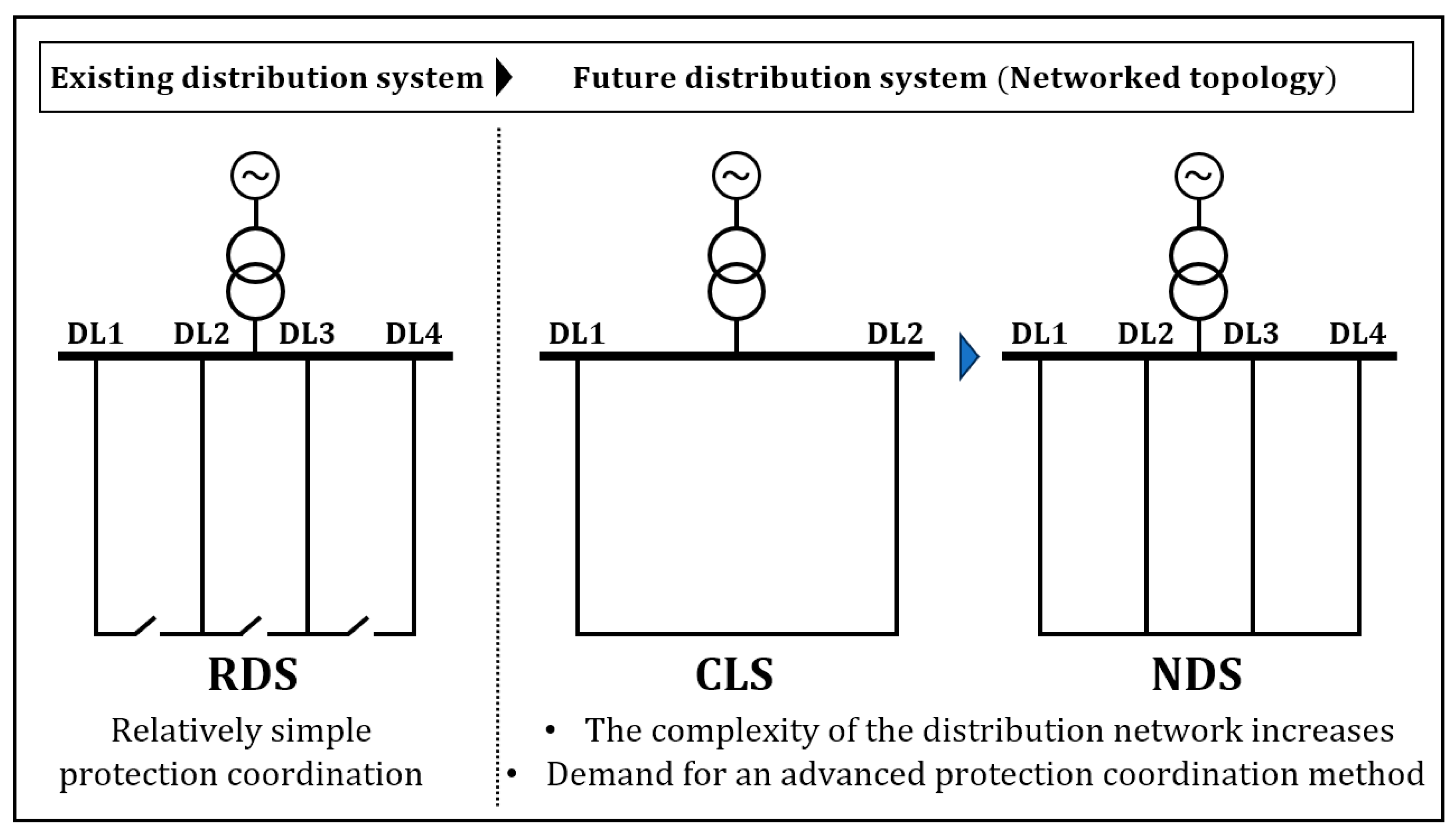
1.2. Transition in Distribution System Topologies
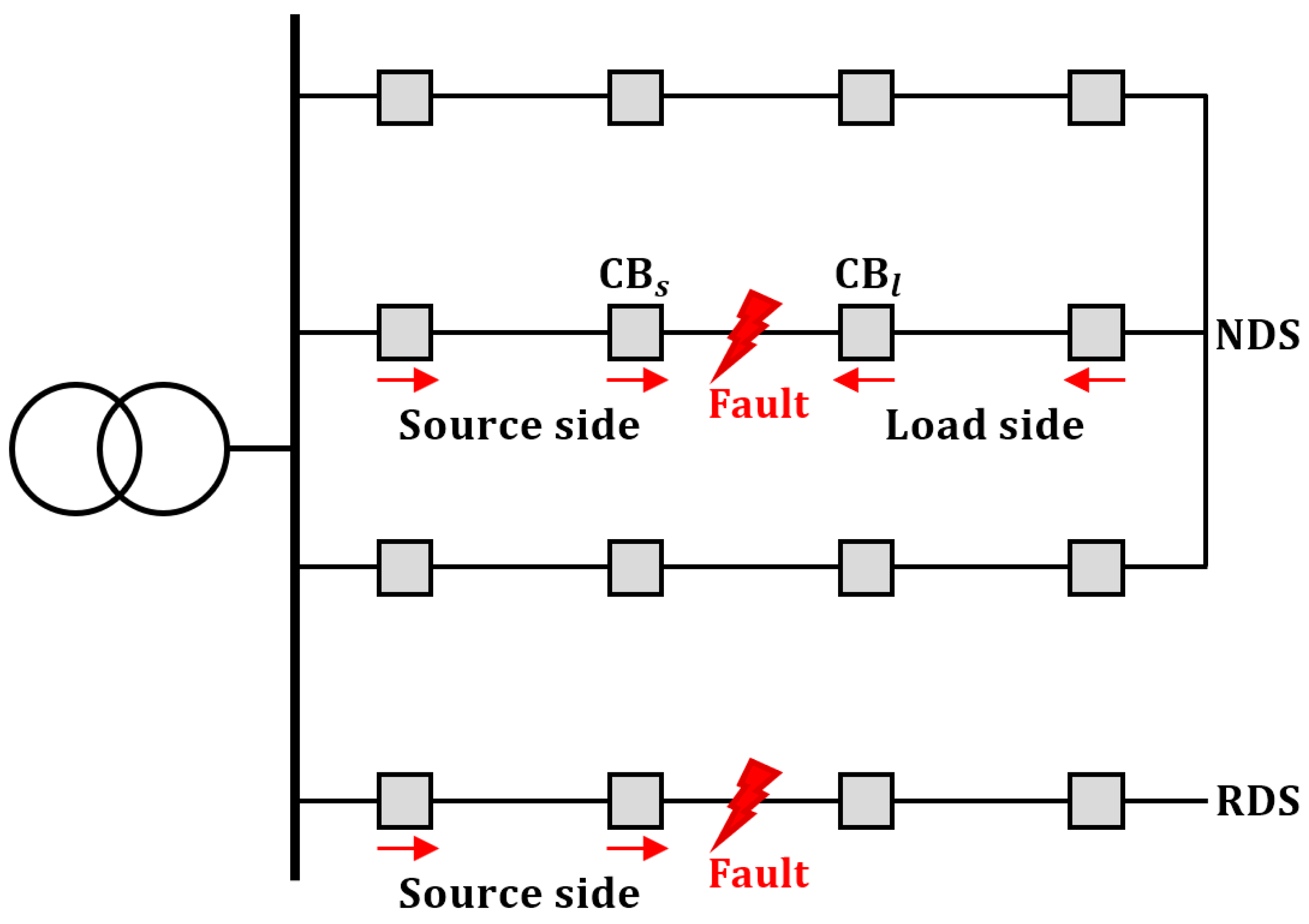
1.3. Protection Coordination in the NDS
1.4. Contributions
- A protection method for the NDS system with a modified time-current curve (TCC) formula is proposed. Since this method is a communication-less method, there is no concern about protection failures caused by communication errors.
- The proposed method is cost-effective because it does not require new devices such as BTB converters and SCFCLs to provide an advanced protection coordination solution in the NDS.
- The proposed method reflects both features from the TCC of the existing overcurrent relay (OCR) and fault impedance, which ensures faster fault clearance and has less probability of malfunction compared to the conventional OCR-based protection scheme.
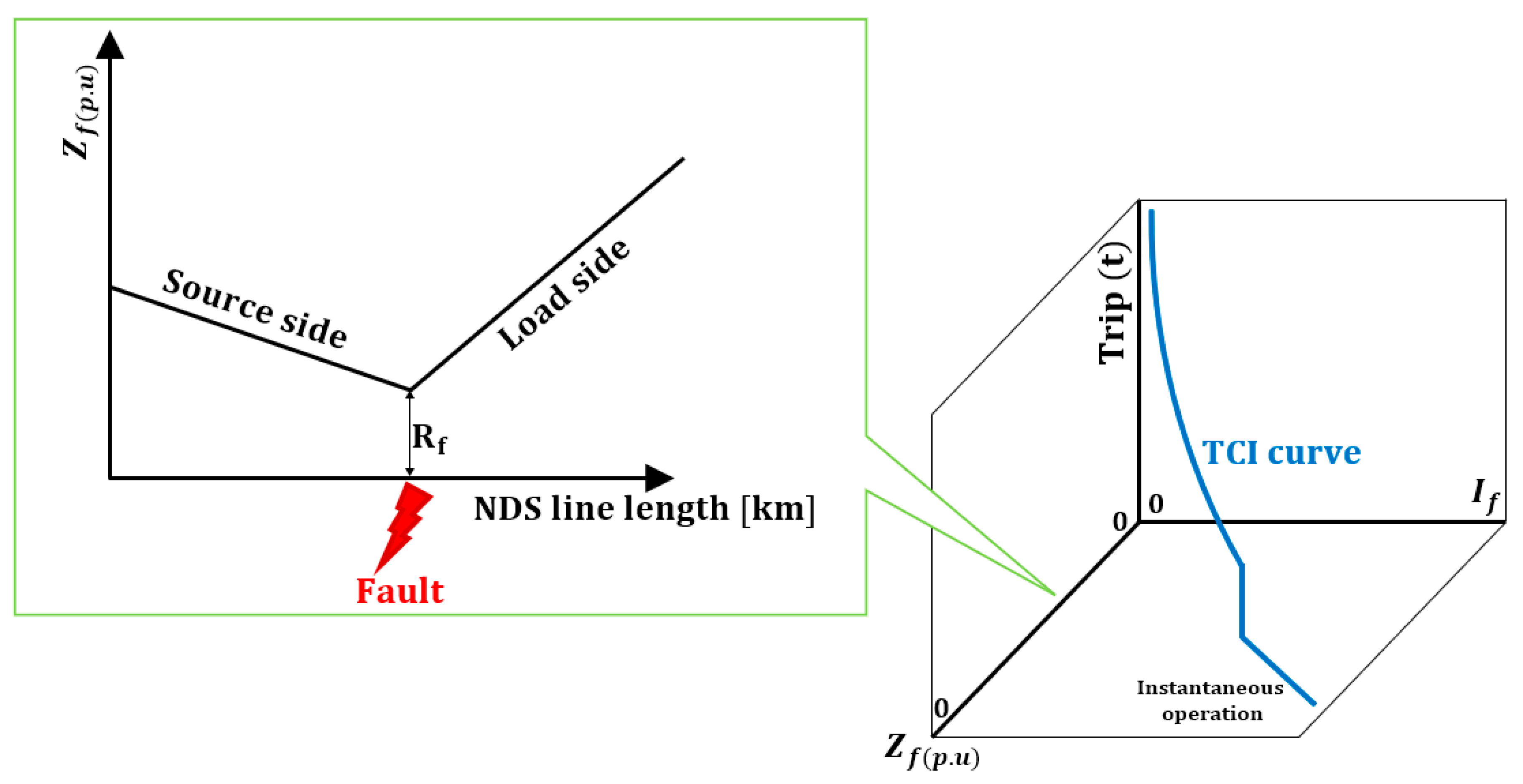
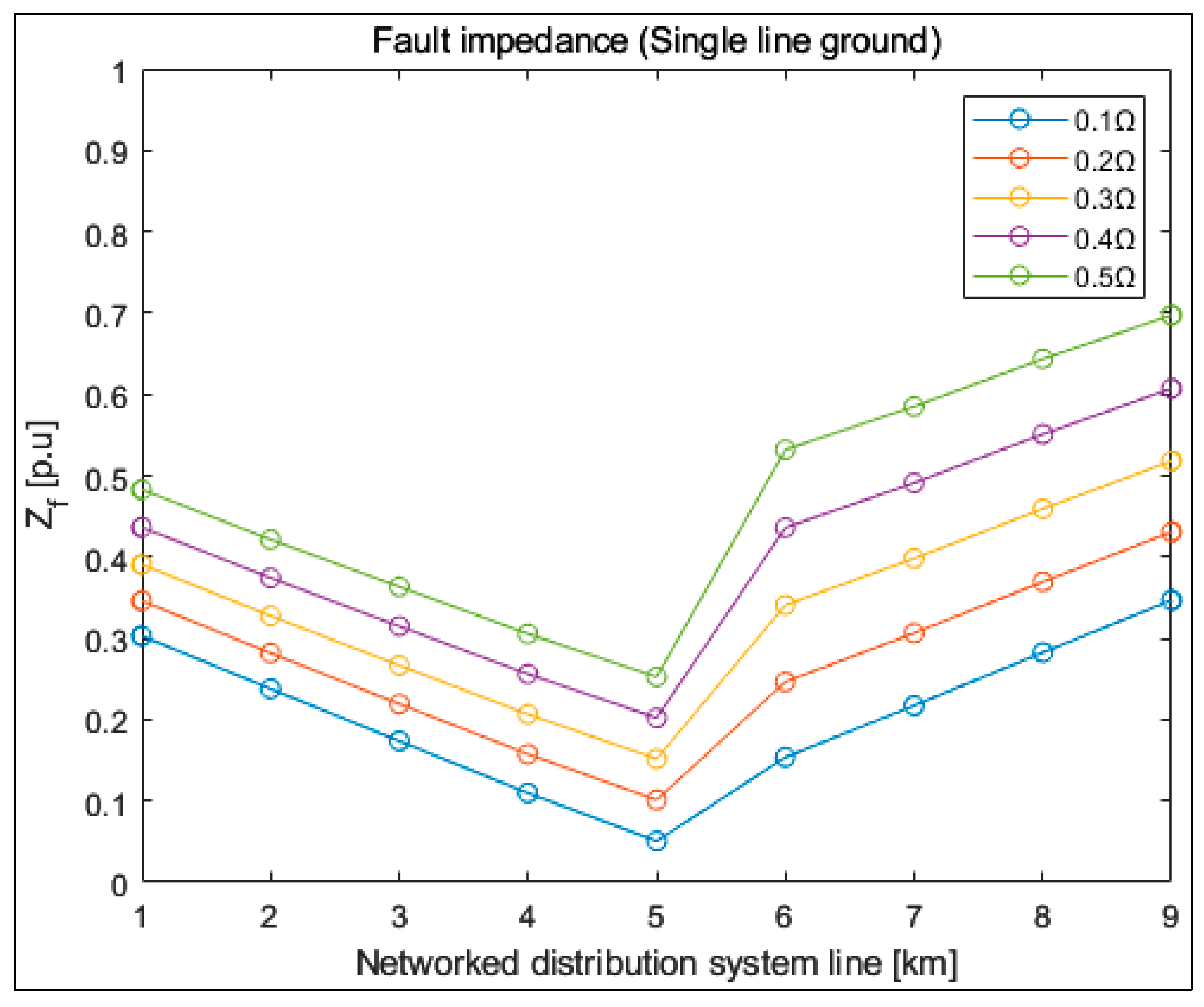
- The exact fault location can be inferred from the magnitude of the fault impedance (fault voltage/fault current), which depends on the location. Therefore, it is expected that it can be continuously used in the development of protection schemes and devices in various systems in the future.
- The time-current-impedance (TCI) characteristic takes advantage of the time-current-voltage (TCV) curve and enables more sensitive operation.
- The proposed protection algorithm can be applied to the NDS and RDS systems, making it more versatile.
2. Theoretical Background
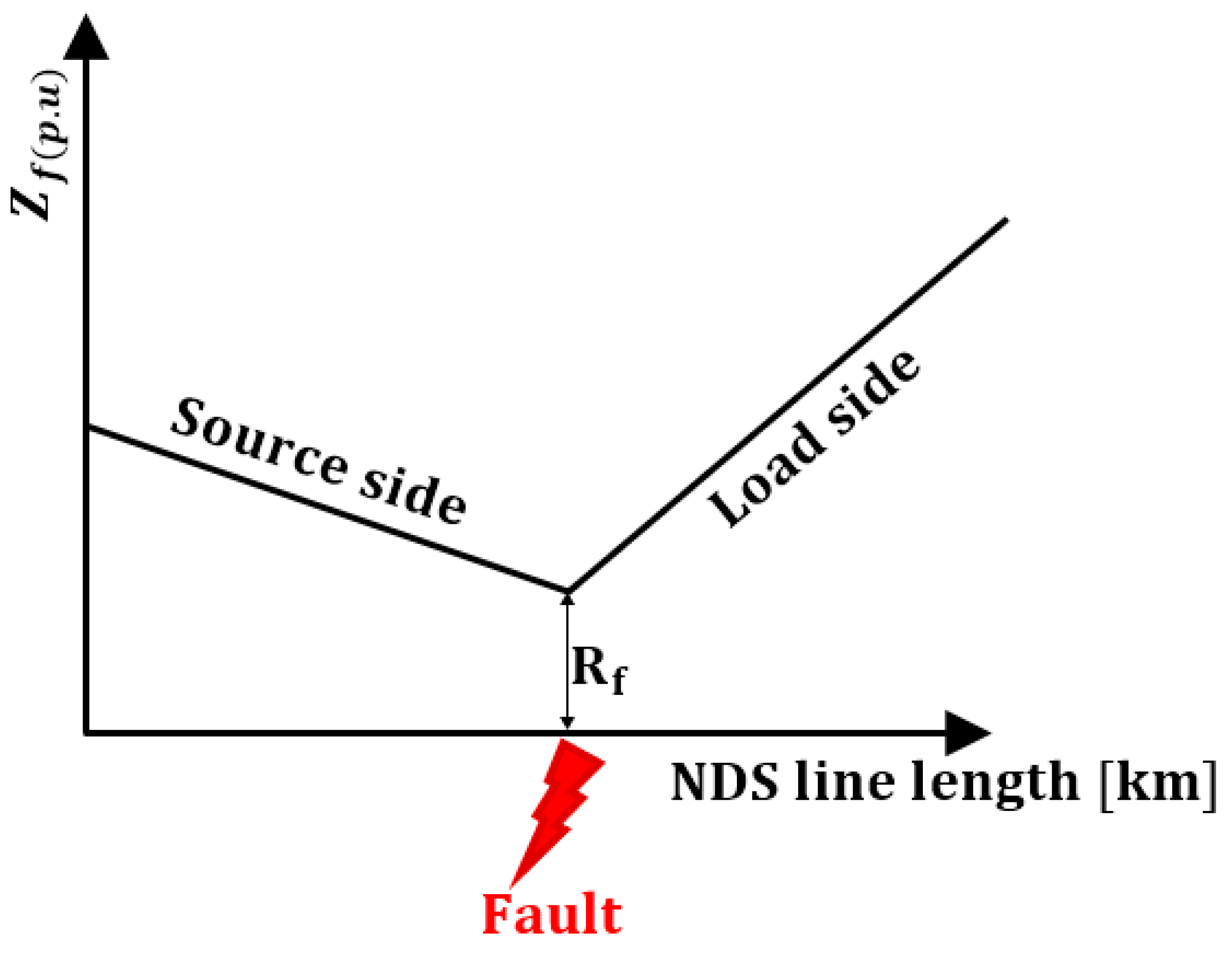
2.1. Fault Impedance Characteristics
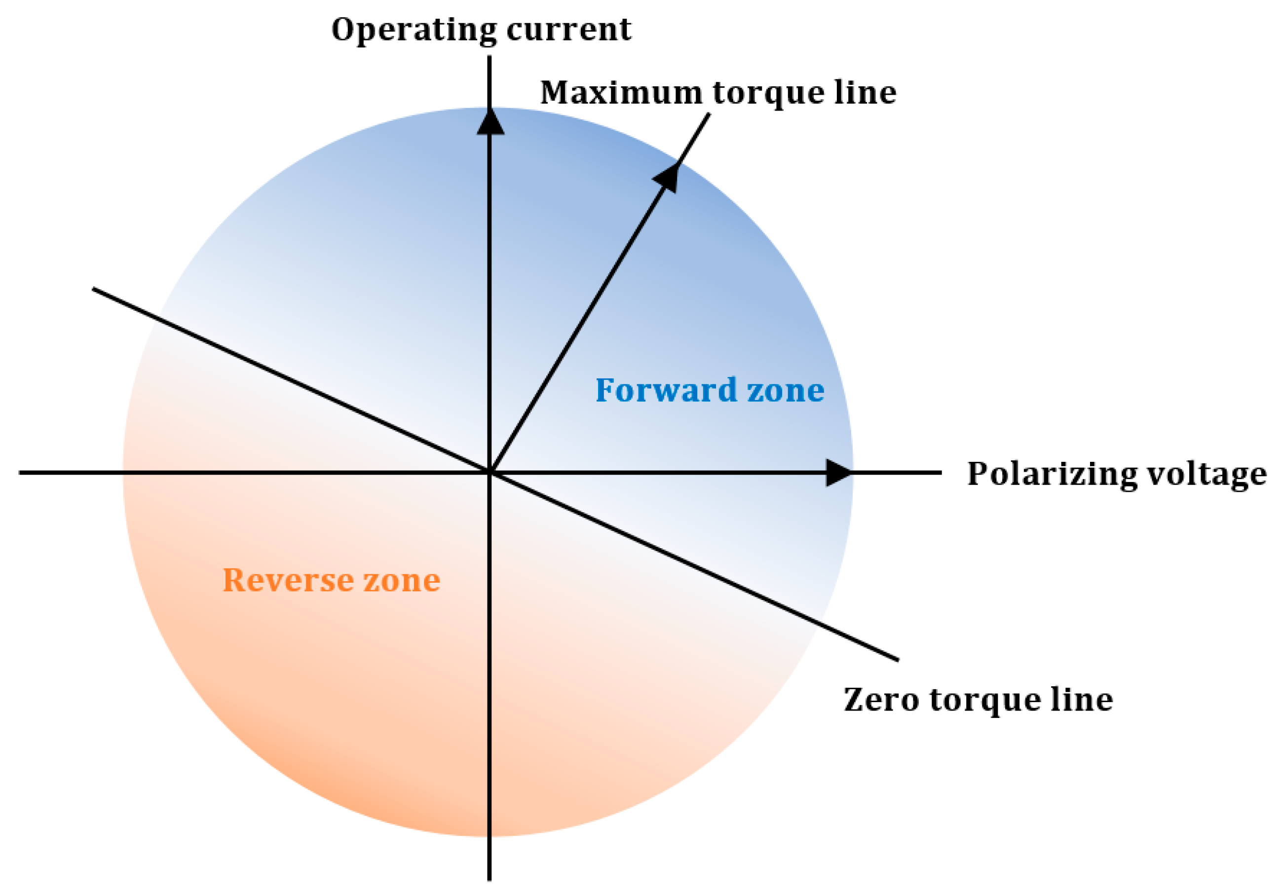
2.2. Fault Current Analysis and Direction Detection
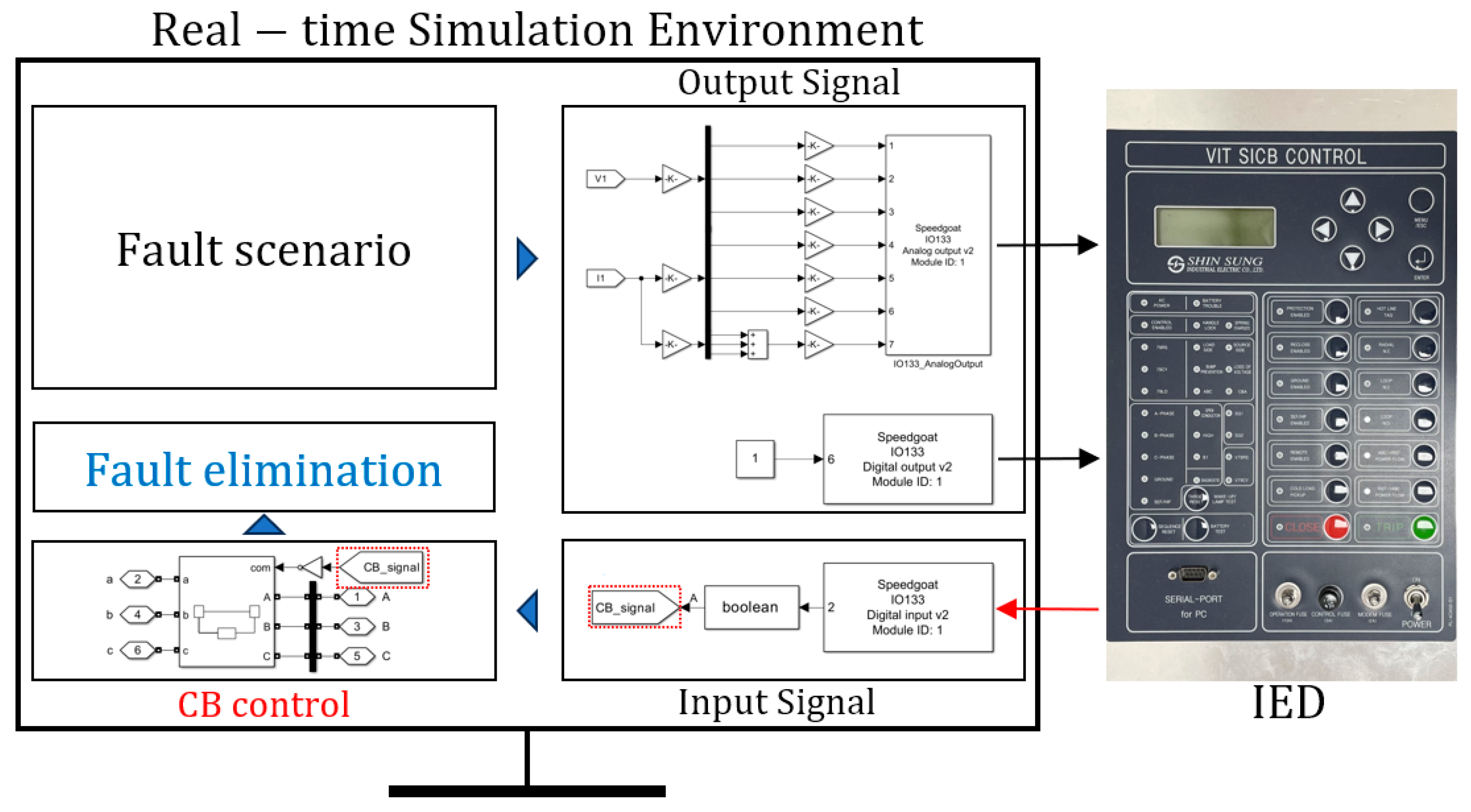
2.3. Overview of Protection Coordination Using HILS
3. Proposed Method
3.1. Time Current Impedance (TCI) Formula
3.2. Protection Scheme Algorithm
4. Validation
4.1. Simulation Environment
4.1.1. Simulation Environment Setup
4.1.2. Simulation Result and Discussion
4.2. Real-Time Environment
4.2.1. Simulation Environment Setup
4.2.2. HILS Result and Discussion
5. Conclusions
Author Contributions
Funding
Institutional Review Board Statement
Informed Consent Statement
Data Availability Statement
Acknowledgments
Conflicts of Interest
References
- Guerrero, J.M.; Blaabjerg, F.; Zhelev, T.; Hemmes, K.; Monmasson, E.; Jemei, S.; Comech, M.P.; Granadino, R.; Frau, J.I. Distributed generation: Toward a new energy paradigm. IEEE Ind. Electron. Mag. 2010, 4, 52–64. [Google Scholar] [CrossRef]
- Strachan, N.; Dowlatabadi, H. Distributed generation and distribution utilities. Energy Policy 2002, 30, 649–661. [Google Scholar] [CrossRef]
- Roy; Kumar, N.; Pota, H.R. Current Status and Issues of Concern for the Integration of Distributed Generation into Electricity Networks. IEEE Syst. J. 2014, 9, 933–944. [Google Scholar] [CrossRef]
- Hossain, E.; Tur, M.R.; Padmanaban, S.; Ay, S.; Khan, I. Analysis and Mitigation of Power Quality Issues in Distributed Generation Systems Using Custom Power Devices. IEEE Access 2018, 6, 16816–16833. [Google Scholar] [CrossRef]
- Coster, E.J.; Myrzik, J.M.A.; Kruimer, B.; Kling, W.L. Integration Issues of Distributed Generation in Distribution Grids. Proc. IEEE 2010, 99, 28–39. [Google Scholar] [CrossRef]
- Renders, B.; De Gussemé, K.; Ryckaert, W.R.; Vandevelde, L. Converter-connected distributed generation units with integrated harmonic voltage damping and harmonic current compensation function. Electr. Power Syst. Res. 2009, 79, 65–70. [Google Scholar] [CrossRef]
- Kuang, H.; Li, S.; Wu, Z. Discussion on advantages and disadvantages of distributed generation connected to the grid. In Proceedings of the 2011 International Conference on Electrical and Control Engineering, Yichang, China, 16–18 September 2011; pp. 170–173. [Google Scholar]
- Ismael, S.M.; Abdel Aleem, S.H.E.; Abdelaziz, A.Y.; Zobaa, A.F. State-of-the-art of hosting capacity in modern power systems with distributed generation. Renew. Energy 2019, 130, 1002–1020. [Google Scholar] [CrossRef]
- Jacob; Anna, R.; Zhang, J. Distribution Network Reconfiguration to Increase Photovoltaic Hosting Capacity. In Proceedings of the 2020 IEEE Power & Energy Society General Meeting (PESGM), Montreal, QC, Canada, 2–6 August 2020; pp. 1–5. [Google Scholar]
- Kolenc, M.; Papič, I.; Blažič, B. Assessment of maximum distributed generation penetration levels in low voltage networks using a probabilistic approach. Int. J. Electr. Power Energy Syst. 2015, 64, 505–515. [Google Scholar] [CrossRef]
- Sakar, S.; Balci, M.E.; Abdel Aleem, S.H.A.; Zobaa, A.F. Increasing PV hosting capacity in distorted distribution systems using passive harmonic filtering. Electr. Power Syst. Res. 2017, 148, 74–86. [Google Scholar] [CrossRef]
- Rahi, S.B.; Bisui, S.; Misra, S.C. Identifying critical challenges in the adoption of cloud-based services. Int. J. Commun. Syst. 2017, 30, e3261. [Google Scholar] [CrossRef]
- Wiboonrat, M. Risk anatomy of data center power distribution systems. In Proceedings of the 2008 IEEE International Conference on Sustainable Energy Technologies, Singapore, 24–27 November 2008; pp. 674–679. [Google Scholar]
- Shuai, M.; Chengzhi, W.; Shiwen, Y.; Hao, G.; Jufang, Y.; Hui, H. Review on economic loss assessment of power outages. Procedia Comput. Sci. 2018, 130, 1158–1163. [Google Scholar] [CrossRef]
- Alvarez-Herault, M.-C.; N’doye, N.; Gandioli, C.; Hadjsaid, N.; Tixador, P. Meshed distribution network vs reinforcement to increase the distributed generation connection. Sustain. Energy Grids Netw. 2015, 1, 20–27. [Google Scholar] [CrossRef]
- Davoudi, M.; Cecchi, V.; Agüero, J.R. Investigating the ability of meshed distribution systems to increase penetration levels of Distributed Generation. In Proceedings of the IEEE SOUTHEASTCON 2014, Lexington, KY, USA, 13–16 March 2014; pp. 1–5. [Google Scholar]
- Celli, G.; Pilo, F.; Pisano GI UD IT, T.A.; Allegranza, V.; Cicoria, R.; Iaria, A. Meshed vs. radial MV distribution network in presence of large amount of DG. In Proceedings of the IEEE PES Power Systems Conference and Exposition 2004, New York, NY, USA, 10–13 October 2004; Volume 2, pp. 709–714. [Google Scholar]
- Sharaf, H.M.; Zeineldin, H.H.; Ibrahim, D.K.; El Zahab EE, D.A. Protection coordination of directional overcurrent relays considering fault current direction. In Proceedings of the IEEE PES Innovative Smart Grid Technologies, Istanbul, Turkey, 12–15 October 2014; pp. 1–5. [Google Scholar]
- Saleh, K.A.; Zeineldin, H.H.; Al-Hinai, A.; El-Saadany, E.F. Optimal coordination of directional overcurrent relays using a new time–current–voltage characteristic. IEEE Trans. Power Deliv. 2014, 30, 537–544. [Google Scholar] [CrossRef]
- Zeineldin, H.H.; Sharaf, H.M.; Ibrahim, D.K.; El-Zahab, E.E.-D.A. Optimal Protection Coordination for Meshed Distribution Systems with DG Using Dual Setting Directional Over-Current Relays. IEEE Trans. Smart Grid 2014, 6, 115–123. [Google Scholar] [CrossRef]
- Tsimtsios, A.M.; Korres, G.N.; Nikolaidis, V.C. A pilot-based distance protection scheme for meshed distribution systems with distributed generation. Int. J. Electr. Power Energy Syst. 2019, 105, 454–469. [Google Scholar] [CrossRef]
- Cao, W.; Wu, J.; Jenkins, N.; Wang, C.; Green, T. Operating principle of Soft Open Points for electrical distribution network operation. Appl. Energy 2016, 164, 245–257. [Google Scholar] [CrossRef]
- Gandioli, C.; Alvarez-Hérault, M.-C.; Tixador, P.; Hadjsaid, N.; Medina, D.-M.R. Innovative distribution networks planning integrating superconducting fault current limiters. IEEE Trans. Appl. Supercond. 2013, 23, 5603904. [Google Scholar] [CrossRef]
- Bouchahdane, M.; Bouhadda, W.I.; Chikhi, B.; Eltom, A. Study and Testing of the Directional Phase Overcurrent Protection and the RCA’s Impact on Its Performance and Directional Decision Making. In Proceedings of the 2022 7th International Conference on Environment Friendly Energies and Applications (EFEA), Bagatelle Moka MU, Mauritius, 14–16 December 2022; pp. 1–6. [Google Scholar]
- Momoh, J.A.; Surender Reddy, S. Value of Hardware-In-Loop for experimenting microgrid performance system studies. In Proceedings of the 2016 IEEE PES PowerAfrica, Livingstone, Zambia, 28 June–3 July 2016; pp. 199–203. [Google Scholar]




| Symbol | Description |
|---|---|
| Function for zero-sequence direction detection | |
| Measured zero-sequence voltage | |
| Measured zero-sequence current | |
| Function for positive-sequence direction detection | |
| Measured positive-sequence voltage | |
| Measured positive-sequence current |
| Symbol | Description |
|---|---|
| Relay operating time | |
| Time dial setting parameter | |
| Fault current | |
| Pickup current | |
| Type decision variable of TCC | |
| Fault impedance (p.u) |
| Parameter | Value |
|---|---|
| ) | |
| Transformer impedance (154/6.6/22.9 kV) | |
| CNCV-325 line impedance | |
| DL1 | DL2 | DL3 | DL4 | |||||||||||||||||
|---|---|---|---|---|---|---|---|---|---|---|---|---|---|---|---|---|---|---|---|---|
| S - CB1 | CB1 - R1 | R1 - R2 | R2 - R3 | R3 - R12 | S - CB2 | CB2 - R4 | R4 - R5 | R5 - R6 | R6 -R12, R23 | S - CB3 | CB3 - R7 | R7 - R8 | R8 - R9 | R9 -R23, R34 | S - CB4 | CB4 - R10 | R10 - R11 | R11 - R12 | R12 - R34 | |
| Section Length [km] | 1 | 2 | 2 | 2 | 1.5 | 1 | 2 | 2 | 2 | 1.5 | 1 | 2 | 2 | 2 | 1.5 | 1 | 2 | 2 | 2 | 1.5 |
| Case 1 Load [MW] | - | 2 | 2 | 2 | 2 | - | 2 | 2 | 2 | 2 | - | 2 | 2 | 2 | 2 | - | 2 | 2 | 2 | 2 |
| Case 2 Load [MW] | - | 2.21 | 2.15 | 1.62 | 1.58 | - | 2.55 | 1.89 | 1.56 | 1.42 | - | 1.71 | 1.94 | 3.11 | 1.91 | - | 1.12 | 1.65 | 2.62 | 1.83 |
| Fault Type | [Ω] | F1 | F2 | F3 | F4 | F5 | F6 | F7 | F8 | |||||||||
|---|---|---|---|---|---|---|---|---|---|---|---|---|---|---|---|---|---|---|
| Source | Load | Source | Load | Source | Load | Source | Load | Source | Load | Source | Load | Source | Load | Source | Load | |||
| Conventional method | AG | 0.01 | 0.102 | 0.150 | 0.102 | 0.204 | 0.057 | 0.159 | 0.081 | 0.183 | 0.102 | 0.147 | 0.044 | 0.146 | 0.061 | 0.163 | 0.092 | 0.138 |
| 0.1 | 0.102 | 0.151 | 0.102 | 0.204 | 0.058 | 0.160 | 0.083 | 0.185 | 0.102 | 0.148 | 0.045 | 0.147 | 0.062 | 0.164 | 0.094 | 0.140 | ||
| 1 | 0.102 | 0.160 | 0.122 | 0.224 | 0.081 | 0.183 | 0.106 | 0.208 | 0.102 | 0.157 | 0.056 | 0.158 | 0.078 | 0.180 | 0.121 | 0.179 | ||
| ABC Short | 0.01 | 0.101 | 0.203 | 0.102 | 0.204 | 0.254 | 0.356 | 0.385 | 0.487 | 0.101 | 0.223 | 0.102 | 0.204 | 0.270 | 0.372 | 0.443 | 0.545 | |
| 0.1 | 0.101 | 0.203 | 0.102 | 0.204 | 0.255 | 0.357 | 0.387 | 0.489 | 0.102 | 0.204 | 0.103 | 0.205 | 0.271 | 0.373 | 0.445 | 0.547 | ||
| 1 | 0.101 | 0.333 | 0.123 | 0.225 | 0.272 | 0.374 | 0.416 | 0.518 | 0.121 | 0.223 | 0.124 | 0.226 | 0.290 | 0.392 | 0.479 | 0.581 | ||
| Proposed method | AG | 0.01 | 0.010 | 0.024 | 0.013 | 0.026 | 0.014 | 0.027 | 0.015 | 0.026 | 0.010 | 0.024 | 0.013 | 0.026 | 0.014 | 0.026 | 0.015 | 0.028 |
| 0.1 | 0.011 | 0.025 | 0.013 | 0.027 | 0.014 | 0.027 | 0.015 | 0.027 | 0.011 | 0.025 | 0.013 | 0.026 | 0.015 | 0.028 | 0.016 | 0.030 | ||
| 1 | 0.015 | 0.031 | 0.016 | 0.031 | 0.026 | 0.041 | 0.050 | 0.064 | 0.015 | 0.030 | 0.017 | 0.032 | 0.030 | 0.045 | 0.065 | 0.082 | ||
| ABC Short | 0.01 | 0.012 | 0.026 | 0.014 | 0.028 | 0.014 | 0.028 | 0.016 | 0.029 | 0.012 | 0.026 | 0.014 | 0.028 | 0.014 | 0.027 | 0.016 | 0.030 | |
| 0.1 | 0.012 | 0.026 | 0.014 | 0.028 | 0.015 | 0.029 | 0.017 | 0.030 | 0.012 | 0.026 | 0.014 | 0.028 | 0.015 | 0.028 | 0.018 | 0.032 | ||
| 1 | 0.014 | 0.031 | 0.017 | 0.034 | 0.035 | 0.050 | 0.075 | 0.089 | 0.014 | 0.031 | 0.018 | 0.034 | 0.040 | 0.055 | 0.099 | 0.117 | ||
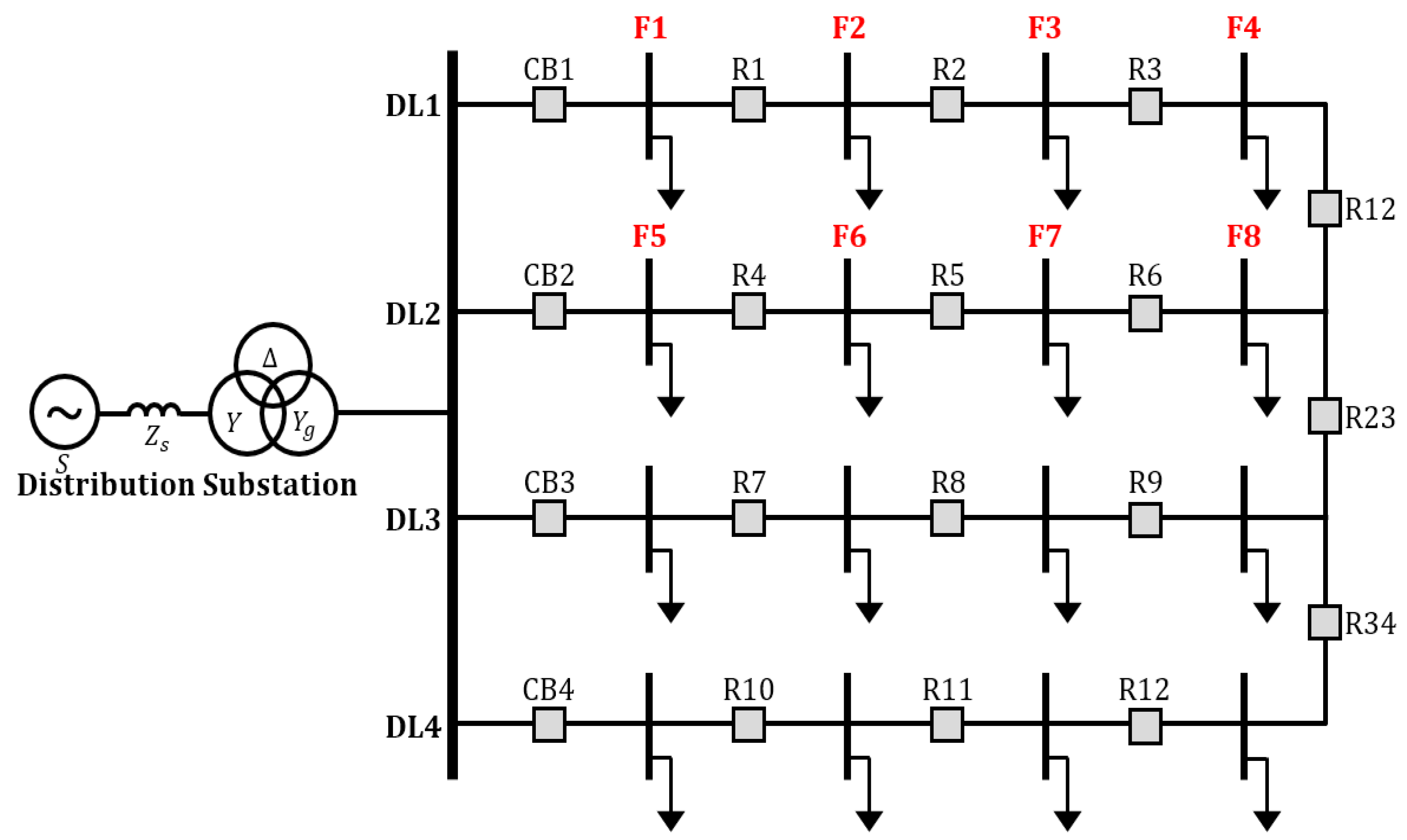
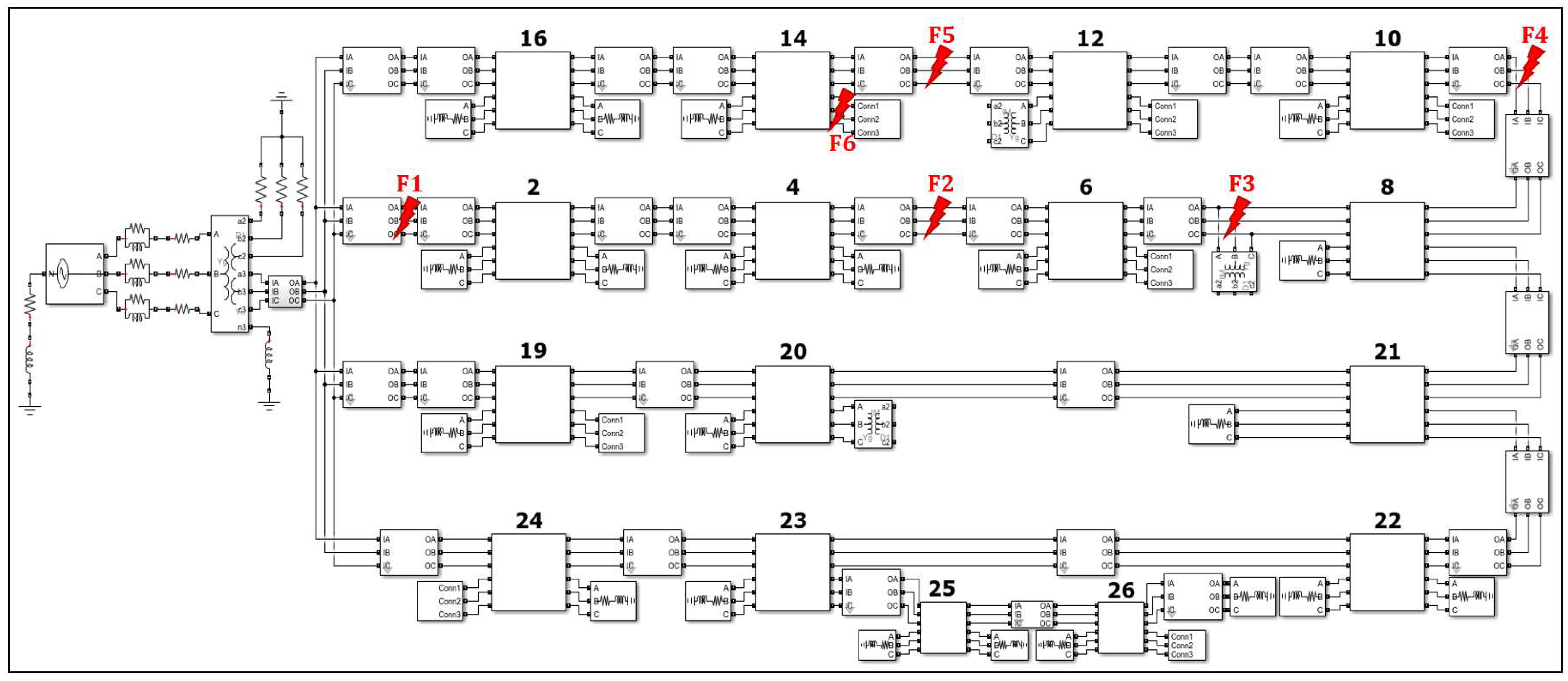
| Fault Number | Fault Test Purpose |
|---|---|
| F1 | Feeder entrance fault scenario |
| F2 | Feeder midpoint fault scenario |
| F3 | DG connection point fault scenario |
| F4 | Feeder terminal interconnection fault scenario |
| F5 | Feeder midpoint fault scenario |
| F6 | Lateral fault scenario |
| DL1 | DL2 | DL3 | DL4 | |||||||||||||||
|---|---|---|---|---|---|---|---|---|---|---|---|---|---|---|---|---|---|---|
| S - CB16 | CB16 - R14 | R14 - R12 | R12 - R10 | R10 - R8 | S - CB2 | CB2 - R4 | R4 - R6 | R6 - R8 | R8 - R8, R21 | S - R19 | R19 - R20 | R20 - R21 | R21 - R8, R22 | S - R24 | R24 - R23 | R23 - R22 | R22 - R21 | |
| Section Length [km] | 0.077 | 0.049 | 0.085 | 0.086 | 0.077 | 0.061 | 0.065 | 0.055 | 0.018 | 0.077 0.017 | 0.03 | 0.04 | 0.04 | 0.017 0.08 | 0.03 | 0.04 | 0.04 | 0.08 |
| Case 3 Load [kW] | - | - | 300 | 300 | 300 | - | 300 | 300 | 600 | - | - | 300 | 300 | - | 300 | - | 600 | - |
| Case 4 DG location [MVA] | - | - | 1 | - | - | - | - | - | 0.5 | - | - | - | 1 | - | - | - | - | - |
| Fault Type | [Ω] | F1 | F2 | F3 | F4 | F5 | F6 | |||||||
|---|---|---|---|---|---|---|---|---|---|---|---|---|---|---|
| Source | Load | Source | Load | Source | Load | Source | Load | Source | Load | Source | Load | |||
| Normal load condition | AG | 0.01 | 0.024 | 0.054 | 0.028 | 0.057 | 0.033 | 0.068 | 0.033 | 0.069 | 0.031 | 0.064 | 0.030 | - |
| 0.1 | 0.025 | 0.056 | 0.033 | 0.060 | 0.036 | 0.077 | 0.041 | 0.087 | 0.032 | 0.067 | 0.031 | - | ||
| 1 | 0.034 | 0.067 | 0.035 | 0.063 | 0.047 | 0.108 | 0.052 | 0.097 | 0.046 | 0.077 | 0.033 | - | ||
| ABC Short | 0.01 | 0.030 | 0.060 | 0.034 | 0.065 | 0.029 | 0.058 | 0.032 | 0.066 | 0.033 | 0.063 | 0.028 | - | |
| 0.1 | 0.032 | 0.060 | 0.034 | 0.066 | 0.035 | 0.074 | 0.034 | 0.067 | 0.033 | 0.064 | 0.03 | - | ||
| 1 | 0.032 | 0.064 | 0.038 | 0.067 | 0.066 | 0.165 | 0.064 | 0.118 | 0.033 | 0.064 | 0.031 | - | ||
| DG connected condition | AG | 0.01 | 0.033 | 0.06 | 0.032 | 0.062 | 0.035 | 0.071 | 0.036 | 0.072 | 0.031 | 0.061 | 0.030 | - |
| 0.1 | 0.033 | 0.06 | 0.033 | 0.064 | 0.046 | 0.083 | 0.037 | 0.082 | 0.031 | 0.061 | 0.030 | - | ||
| 1 | 0.034 | 0.065 | 0.039 | 0.075 | 0.052 | 0.113 | 0.044 | 0.088 | 0.044 | 0.072 | 0.031 | - | ||
| ABC Short | 0.01 | 0.030 | 0.058 | 0.030 | 0.060 | 0.034 | 0.064 | 0.03 | 0.062 | 0.029 | 0.060 | 0.030 | - | |
| 0.1 | 0.030 | 0.059 | 0.034 | 0.067 | 0.035 | 0.074 | 0.033 | 0.068 | 0.032 | 0.061 | 0.030 | - | ||
| 1 | 0.034 | 0.066 | 0.038 | 0.070 | 0.065 | 0.165 | 0.061 | 0.112 | 0.033 | 0.064 | 0.031 | - | ||
Disclaimer/Publisher’s Note: The statements, opinions and data contained in all publications are solely those of the individual author(s) and contributor(s) and not of MDPI and/or the editor(s). MDPI and/or the editor(s) disclaim responsibility for any injury to people or property resulting from any ideas, methods, instructions or products referred to in the content. |
© 2023 by the authors. Licensee MDPI, Basel, Switzerland. This article is an open access article distributed under the terms and conditions of the Creative Commons Attribution (CC BY) license (https://creativecommons.org/licenses/by/4.0/).
Share and Cite
Noh, J.; Gham, S.; Yoon, M.; Chae, W.; Kim, W.; Choi, S. Enhanced Non-Communication-Based Protection Coordination and Advanced Verification Method Using Fault Impedance in Networked Distribution Systems. Sustainability 2023, 15, 15593. https://doi.org/10.3390/su152115593
Noh J, Gham S, Yoon M, Chae W, Kim W, Choi S. Enhanced Non-Communication-Based Protection Coordination and Advanced Verification Method Using Fault Impedance in Networked Distribution Systems. Sustainability. 2023; 15(21):15593. https://doi.org/10.3390/su152115593
Chicago/Turabian StyleNoh, Juan, Seungjun Gham, Myungseok Yoon, Wookyu Chae, Woohyun Kim, and Sungyun Choi. 2023. "Enhanced Non-Communication-Based Protection Coordination and Advanced Verification Method Using Fault Impedance in Networked Distribution Systems" Sustainability 15, no. 21: 15593. https://doi.org/10.3390/su152115593
APA StyleNoh, J., Gham, S., Yoon, M., Chae, W., Kim, W., & Choi, S. (2023). Enhanced Non-Communication-Based Protection Coordination and Advanced Verification Method Using Fault Impedance in Networked Distribution Systems. Sustainability, 15(21), 15593. https://doi.org/10.3390/su152115593


