
Evaluating the Printability and Rheological and Mechanical Properties of 3D-Printed Earthen Mixes for Carbon-Neutral Buildings
Abstract
:1. Introduction
2. Materials and Methods
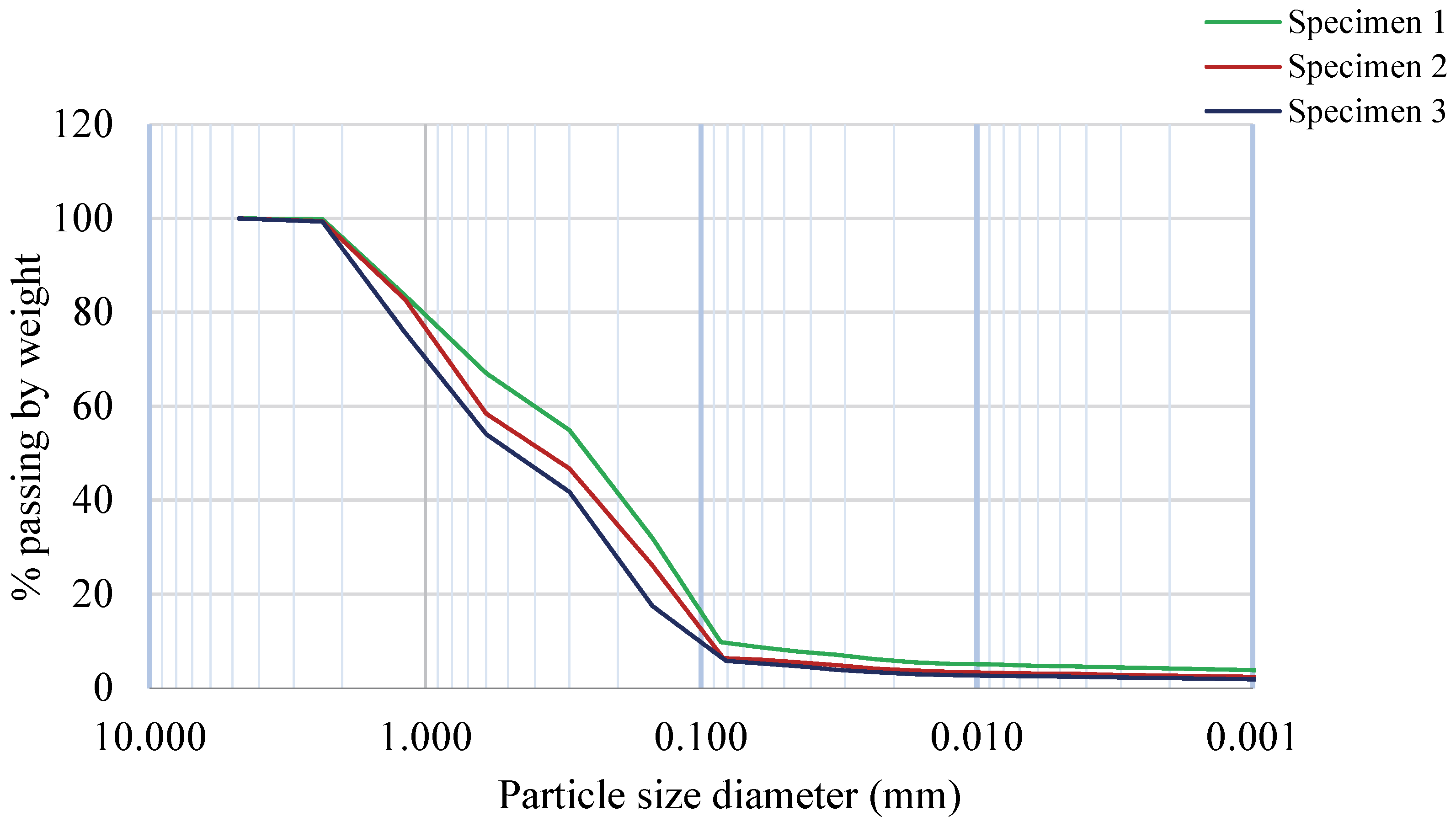
2.1. Preparation of Local Soil
2.2. Soil Mix Design
2.3. Mixing Procedure
2.4. Test Methods
2.4.1. Characterization through XRD and XRF Analysis
2.4.2. Fresh Properties
2.4.3. Hardened Properties
2.4.4. Printability Tests
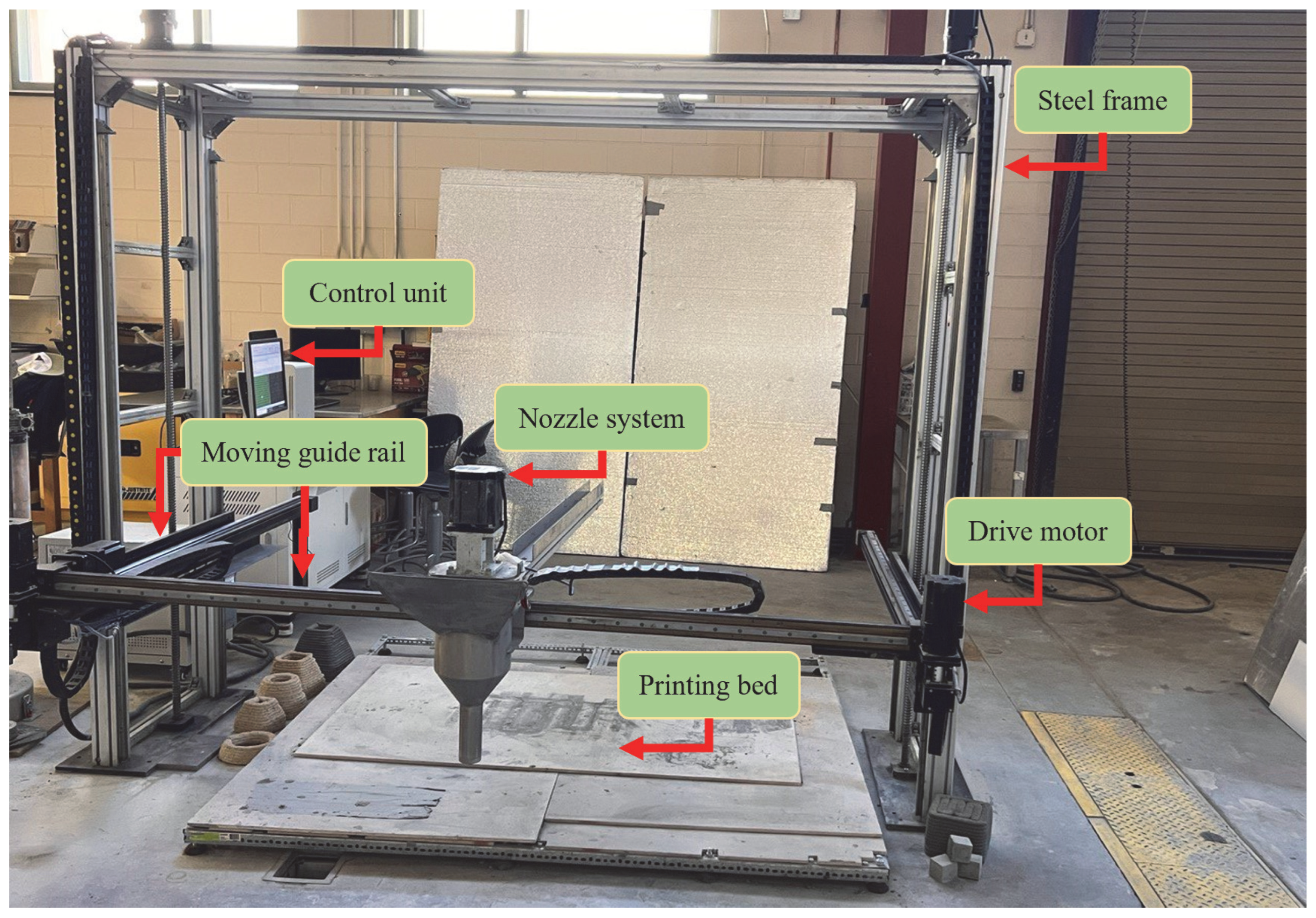
Printing System
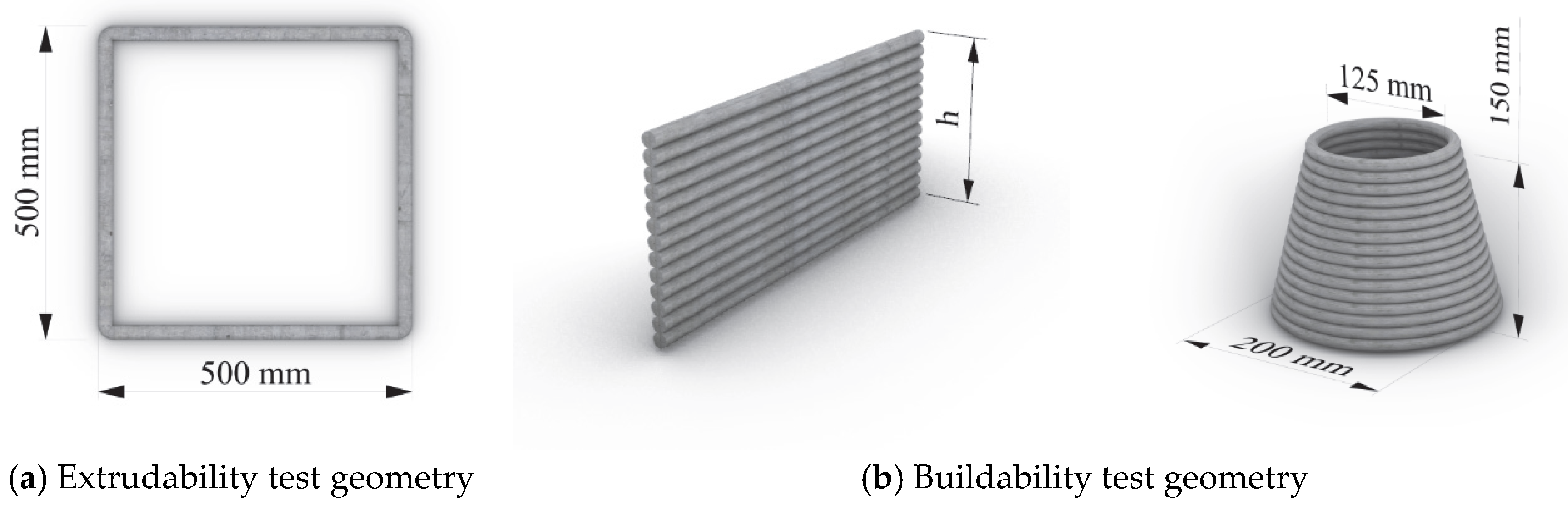
Extrudability Test
Buildability Test
- (1)
- (2)
- Assessing the deformation in the bottommost layer filament of the same single-filament wall printed up to a maximum of 12 layers. Deformations in the bottommost layer were recorded after 7 days of thorough drying (to ensure accurate measurement). Ten readings were collected, and their average deformations, along with standard deviations, were analyzed.
- (3)
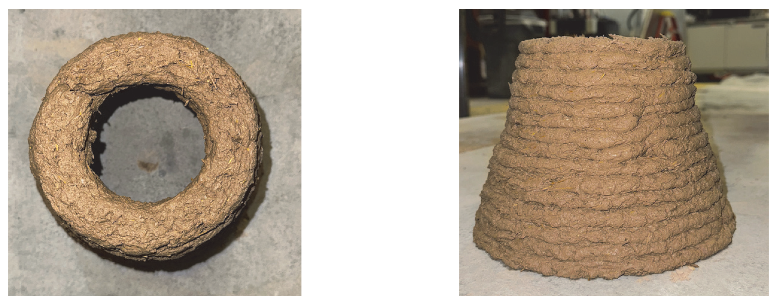
- 3D-printing a circular cone with the mix SLFP for geometrical exploration purposes, as shown in Figure 6b.
3. Results and Discussion
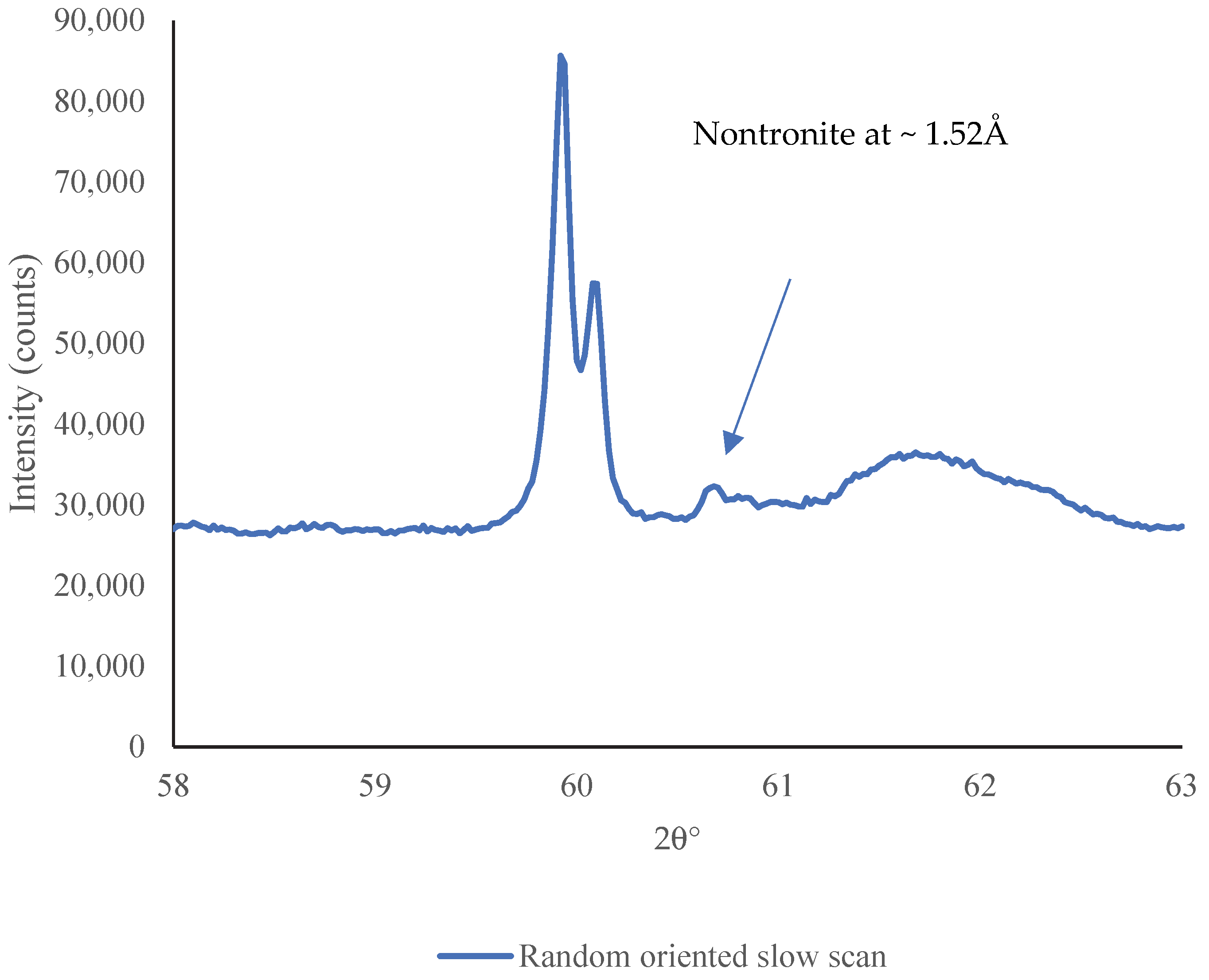
3.1. Characterization through XRD and XRF Analysis
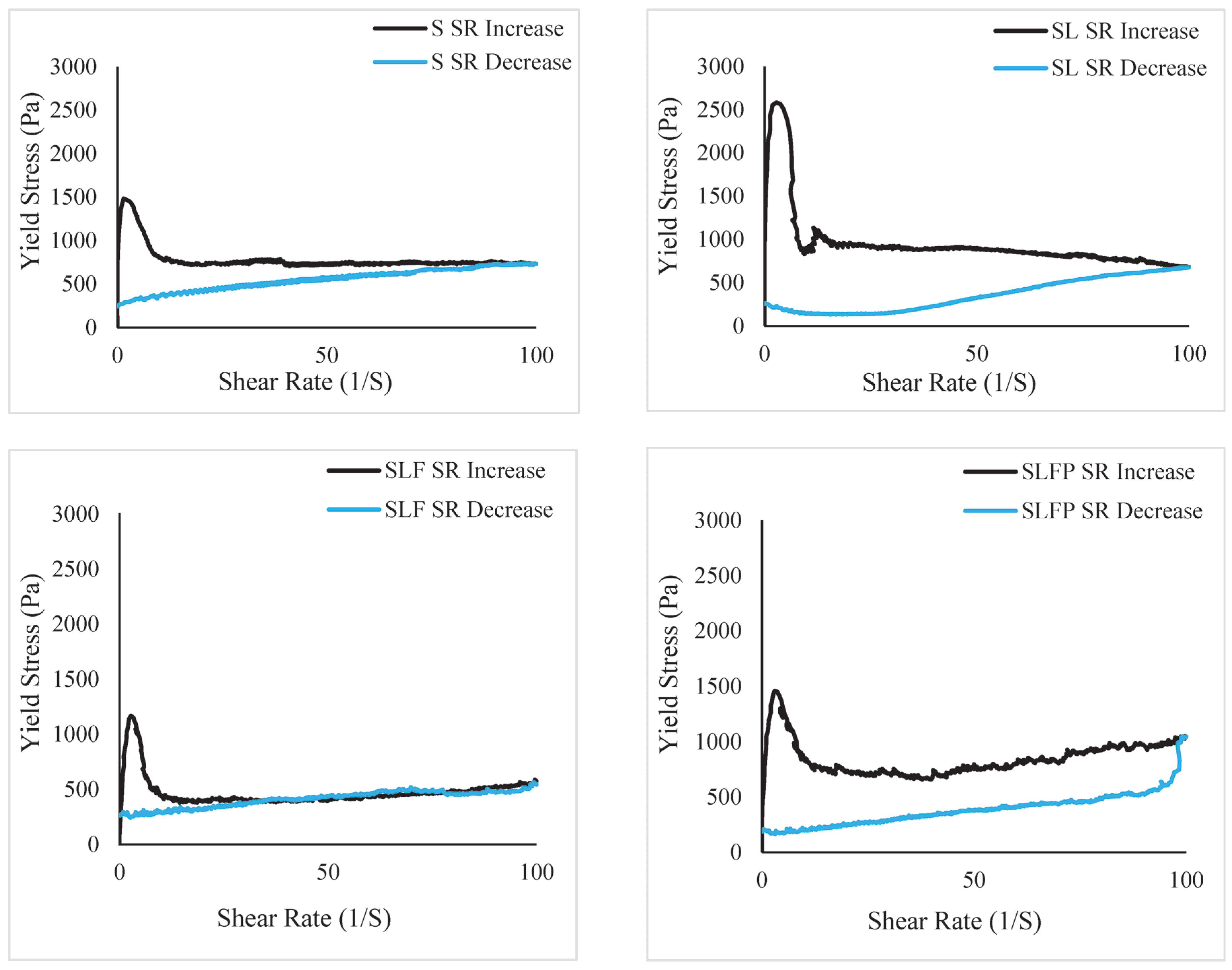
3.2. Fresh Properties


3.3. Hardened Properties
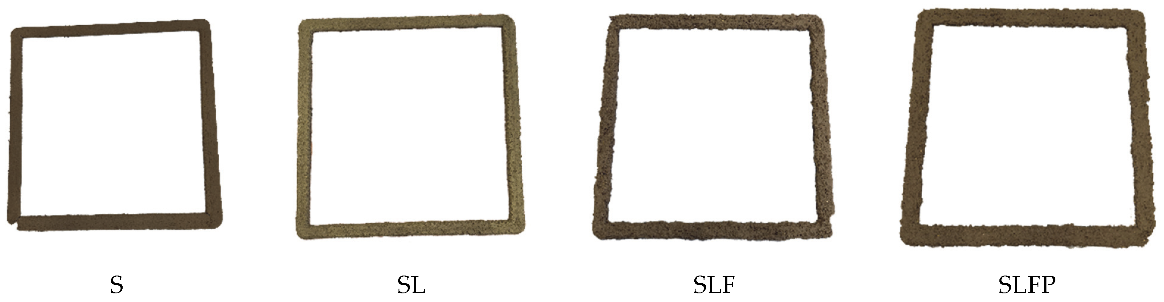
3.3.1. Drying Shrinkage Results
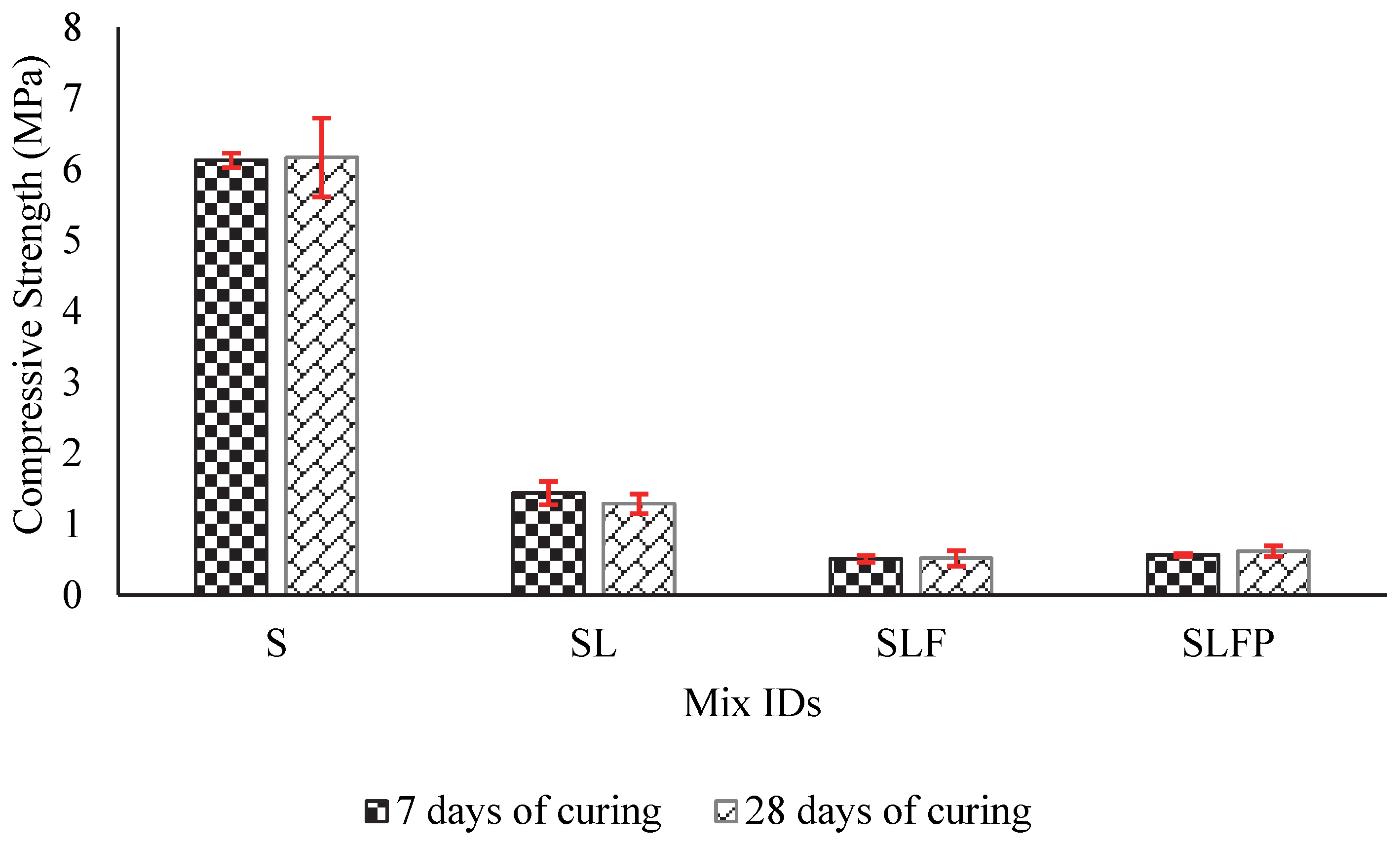
3.3.2. Compressive Strength
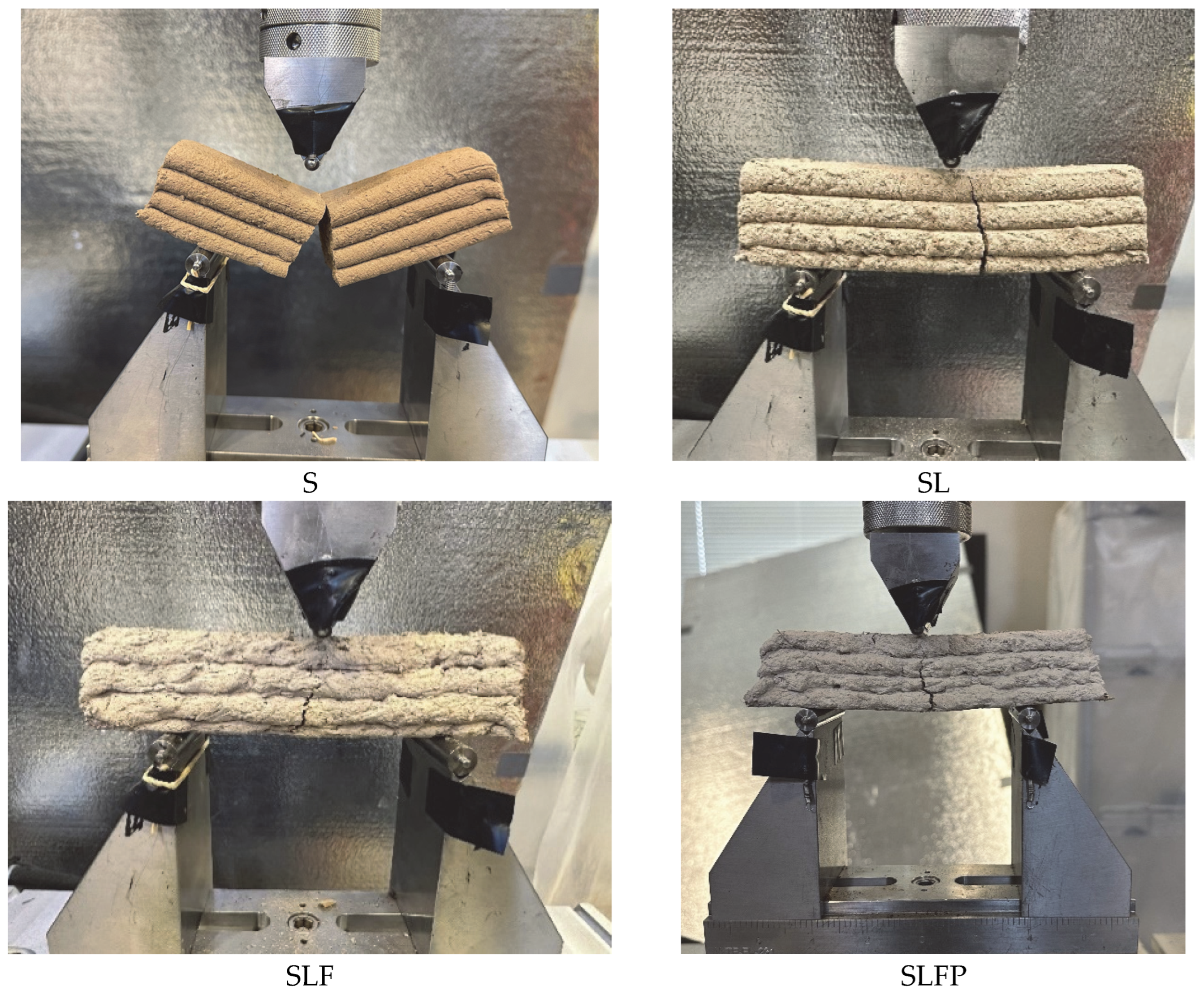
3.3.3. Flexural Strength
3.4. Printability Tests
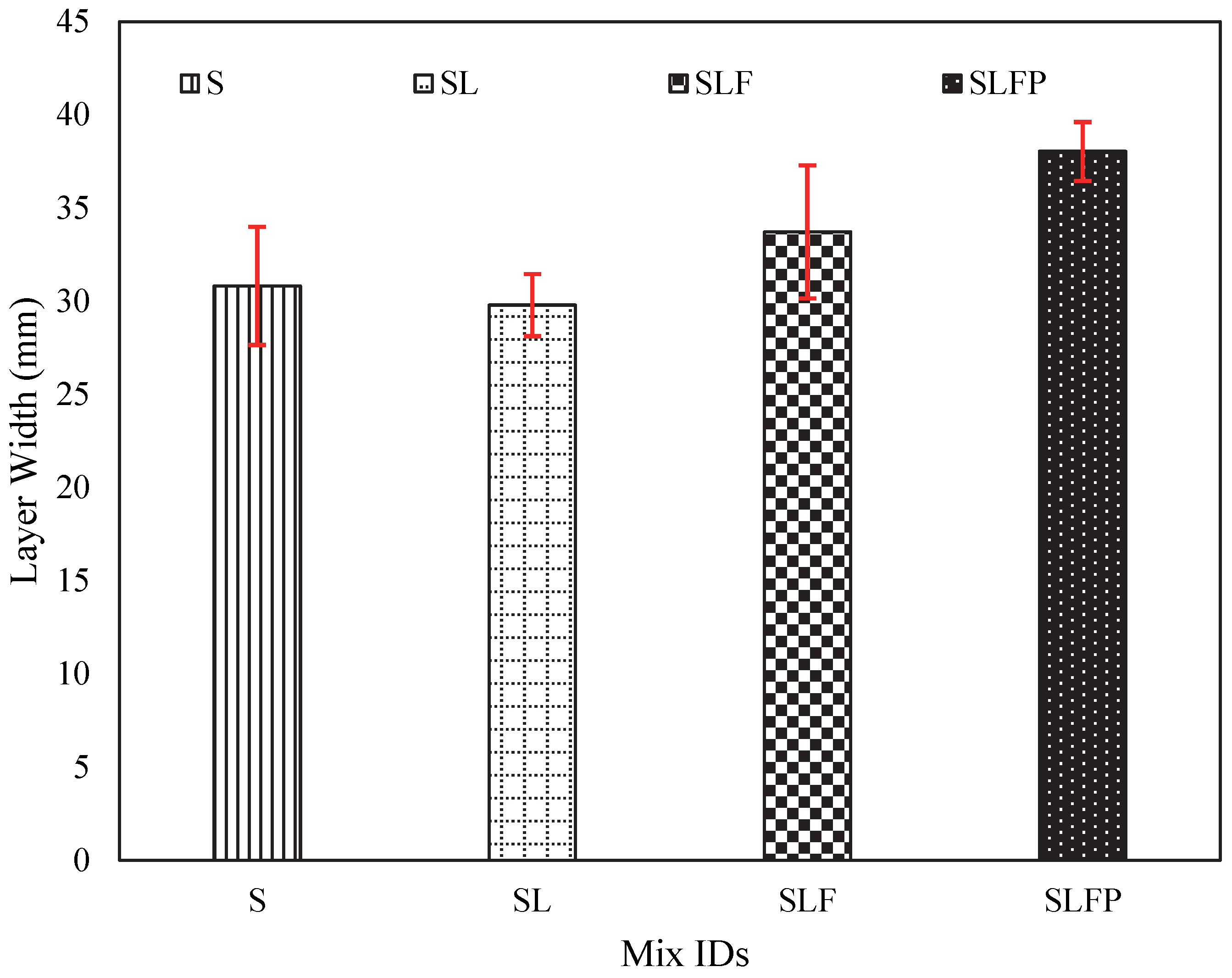
3.4.1. Extrudability
3.4.2. Buildability
- (1)
- Determining the maximum number of stackable layers before structural collapse for a single-filament wall, the results of which are displayed in Table 8. The results clearly indicated that the S mix demonstrated the highest number of stackable printed layers before collapsing, aligning well with the water content in the soil mixes. Mixes with greater water requirements resulted in shorter single-filament walls.
- (2)
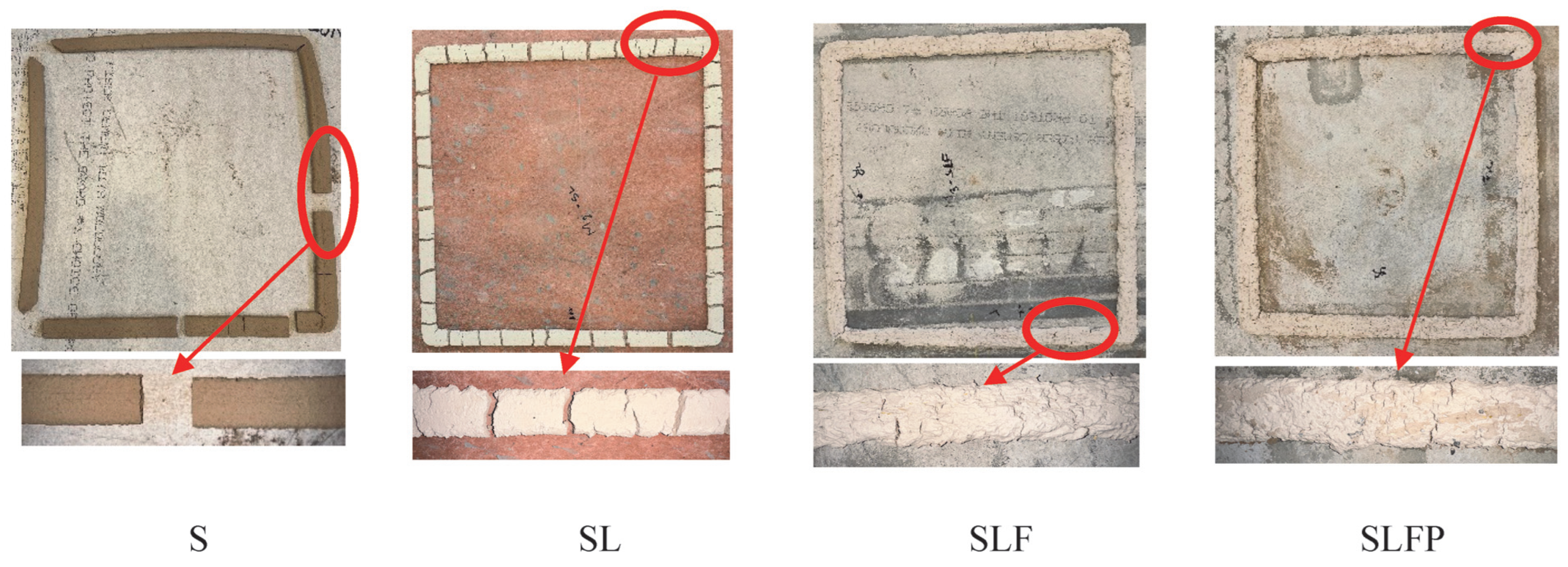
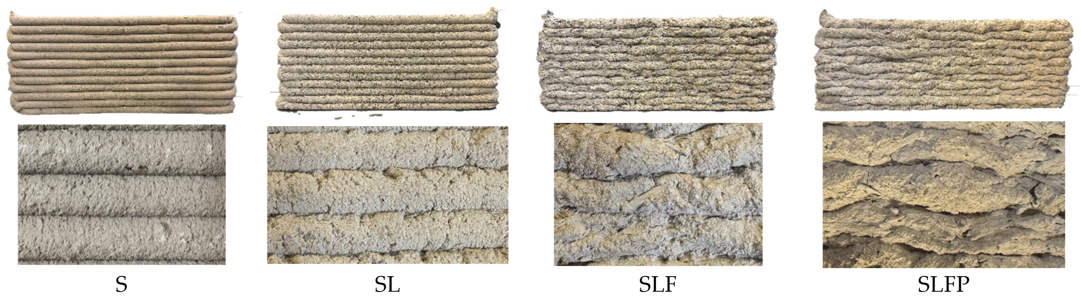
- Evaluating the deformation in the bottommost layer filament of the same single-filament wall, which was printed with a maximum of 12 layers after drying, the results of which are illustrated in Figure 19 and Figure 20. The S mix exhibited the least deformation, while the SLFP mix had the highest average deformation in the lowermost filament layer, 3.67 mm. This deformation was over 50% greater than that observed in mix S. Furthermore, the results obtained from the flow table tests indicated that the SL and SLFP mixes had significantly higher flow values than S and SLF mixes. The outcomes of this evaluation align with the number of stackable layers in Table 8, where larger deformations in the lowermost layer corresponded to shorter single walls and fewer stackable layers. Furthermore, Figure 19 illustrates the 3D printing quality after the fresh mix has undergone drying. As previously noted in the extrudability section, the S mix exhibits the highest printing quality following the drying process.
- (3)
- Printing a circular cone using the SLFP mixture for exploratory purposes related to geometrical considerations, as depicted in Figure 21. This cone was printed primarily to assess the feasibility of 3D printing various geometries, including the hollow cone. However, it is worth noting that SLFP resulted in the shortest 3D-printed single wall and the largest deformation in the bottom layer, even though it successfully printed the cone up to 15 layers. Further research is needed to systematically evaluate geometry’s impact on the printing process.
4. Conclusions
- XRD analysis identified the clay composition, which included 49% kaolinite, 15% nontronite, and 36% illite clay minerals. Identifying nontronite clay, known for its volumetric instability, contributes to the soil mix’s higher susceptibility to shrinkage and greater water retention capacity.
- The soil mixture composed solely of pure soil demonstrated the highest printing quality in both its fresh and hardened states. It successfully produced the tallest single-filament 3D-printed wall, consisting of 18 layers, with minimal deformation in the bottom layer. Furthermore, it exhibited superior mechanical performance in terms of compressive (6.17 MPa) and flexural strength (4.15 MPa). However, due to the high nontronite clay content in the soil, this mixture experienced cracking and significant drying shrinkage after the drying process.
- Incorporating various additives (lime, pozzolana, and fiber) raised the water demand necessary to achieve a printable mixture. Consequently, this led to a shorter single filament 3D-printed wall, increased filament width, and greater deformation in the bottommost layer of the printed wall due to the higher water content.
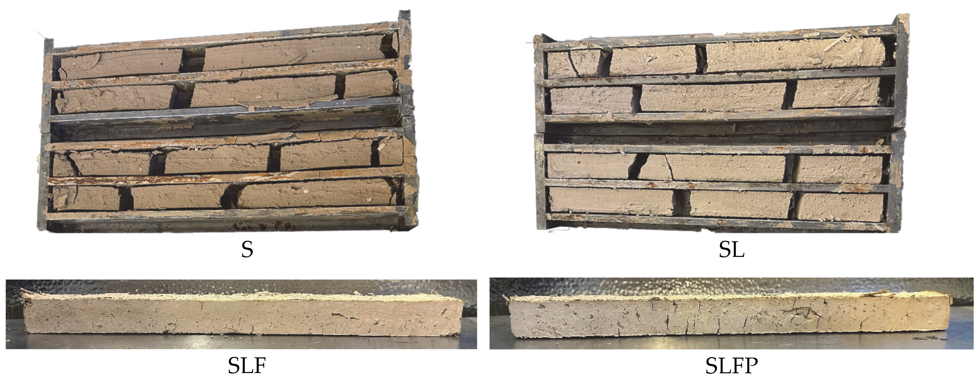
- The incorporation of fibers proved to be highly effective in mitigating excessive shrinkage and reducing both cracking and drying shrinkage. These fibers played a pivotal role in enhancing the cohesion of the specimens and preventing the formation of wide cracks induced by substantial drying shrinkage, whether in cast or 3D-printed specimens. Additionally, the introduction of fibers into the SLFP mix resulted in significant shrinkage reduction and fewer cracks compared to the SLF mix. Specifically, the length shrinkage observed in cast specimens was 7.7% for SLF, and notably reduced to 2.6% for SLFP. Furthermore, the maximum crack widths on extruded specimens decreased from 0.95 mm for SLF to 0.46 mm for SLFP. This demonstrates the beneficial impact of fiber incorporation on the structural integrity and reduced shrinkage of the studied soil mixes.
- Contrary to expectations, the inclusion of lime or pozzolana as a soil stabilizer did not lead to improvements in strength or the prevention of shrinkage. This suggests that further research is needed to identify suitable additives that can enhance the mechanical properties and printability of soil mixes while effectively mitigating large shrinkage and crack development.
- The authors of this paper suggested further research about the possibility of using eco-friendly polymers for shape retention and early age cracking should be carried out. Some potential options are as follows: xanthan gum, guar gum, and anionic polyacrylamide.
Author Contributions
Funding
Institutional Review Board Statement
Informed Consent Statement
Data Availability Statement
Acknowledgments
Conflicts of Interest
References
- Allouzi, R.; Al-Azhari, W.; Allouzi, R. Conventional Construction and 3D Printing: A Comparison Study on Material Cost in Jordan. J. Eng. 2020, 2020, 1424682. [Google Scholar] [CrossRef]
- El-Sayegh, S.; Romdhane, L.; Manjikian, S. A critical review of 3D printing in construction: Benefits, challenges, and risks. Arch. Civ. Mech. Eng. 2020, 20, 34. [Google Scholar] [CrossRef]
- Hossain, M.A.; Zhumabekova, A.; Paul, S.C.; Kim, J.R. A Review of 3D Printing in Construction and Its Impact on the Labor Market. Sustainability 2020, 12, 8492. [Google Scholar] [CrossRef]
- Xu, M.; David, J.M.; Kim, S.H. The fourth industrial revolution: Opportunities and challenges. Int. J. Financ. Res. 2018, 9, 90–95. [Google Scholar] [CrossRef]
- Buswell, R.A.; Thorpe, A.; Soar, R.C.; Gibb, A.G.F. Design, data and process issues for mega-scale rapid manufacturing machines used for construction. Autom. Constr. 2008, 17, 923–929. [Google Scholar] [CrossRef]
- Carneau, P.; Mesnil, R.; Roussel, N.; Baverel, O. Additive manufacturing of cantilever—From masonry to concrete 3D printing. Autom. Constr. 2020, 116, 103184. [Google Scholar] [CrossRef]
- Dielemans, G.; Briels, D.; Jaugstetter, F.; Henke, K.; Dörfler, K. Additive Manufacturing of Thermally Enhanced Lightweight Concrete Wall Elements with Closed Cellular Structures. J. Facade Des. Eng. 2021, 9, 59–72. [Google Scholar] [CrossRef]
- Ma, G.; Li, Z.; Wang, L. Printable properties of cementitious material containing copper tailings for extrusion based 3D printing. Constr. Build. Mater. 2018, 162, 613–627. [Google Scholar] [CrossRef]
- Dehghani Najvani, M.A.; Heras Murcia, D.; Soliman, E.; Reda Taha, M.M. Early-age strength and failure characteristics of 3D printable polymer concrete. Constr. Build. Mater. 2023, 394, 132119. [Google Scholar] [CrossRef]
- Zhu, B.; Pan, J.; Nematollahi, B.; Zhou, Z.; Zhang, Y.; Sanjayan, J. Development of 3D printable engineered cementitious composites with ultra-high tensile ductility for digital construction. Mater. Des. 2019, 181, 108088. [Google Scholar] [CrossRef]
- Rahul, A.V.; Santhanam, M.; Meena, H.; Ghani, Z. Mechanical characterization of 3D printable concrete. Constr. Build. Mater. 2019, 227, 116710. [Google Scholar] [CrossRef]
- Wolfs, R.J.M.; Bos, F.P.; Salet, T.A.M. Hardened properties of 3D printed concrete: The influence of process parameters on interlayer adhesion. Cem. Concr. Res. 2019, 119, 132–140. [Google Scholar] [CrossRef]
- Martens, P.; Mathot, M.; Bos, F.; Coenders, J. Optimising 3D Printed Concrete Structures Using Topology Optimisation. In High Tech Concrete: Where Technology and Engineering Meet; Springer International Publishing: Cham, Switzerlsnd, 2018; pp. 301–309. [Google Scholar] [CrossRef]
- Buswell, R.; Xu, J.; De Becker, D.; Dobrzanski, J.; Provis, J.; Kolawole, J.T.; Kinnell, P. Geometric quality assurance for 3D concrete printing and hybrid construction manufacturing using a standardised test part for benchmarking capability. Cem. Concr. Res. 2022, 156, 106773. [Google Scholar] [CrossRef]
- Yaro, N.S.A.; Sutanto, M.H.; Baloo, L.; Habib, N.Z.; Usman, A.; Yousafzai, A.K.; Ahmad, A.; Birniwa, A.H.; Jagaba, A.H.; Noor, A. A Comprehensive Overview of the Utilization of Recycled Waste Materials and Technologies in Asphalt Pavements: Towards Environmental and Sustainable Low-Carbon Roads. Processes 2023, 11, 2095. [Google Scholar] [CrossRef]
- Barbhuiya, S.; Das, B.B. Life Cycle Assessment of construction materials: Methodologies, applications and future directions for sustainable decision-making. Case Stud. Constr. Mater. 2023, 19, e02326. [Google Scholar] [CrossRef]
- Mohan, M.K.; Rahul, A.V.; De Schutter, G.; Van Tittelboom, K. Extrusion-based concrete 3D printing from a material perspective: A state-of-the-art review. Cem. Concr. Compos. 2021, 115, 103855. [Google Scholar] [CrossRef]
- Narendhran, P.S.; Parthasarathy, S.; Vignesh, S.; Mouliyarasu, A.; Prashanth, S.; Jayaraman, A.; Vasudevan, M. Envisaging Sustainable Building Materials for Earthen Construction Practices. IOP Conf. Ser. Earth Environ. Sci. 2023, 1130, 012015. [Google Scholar] [CrossRef]
- Bui, Q.B.; Morel, J.C.; Tran, V.H.; Hans, S.; Oggero, M. How to Use In-Situ Soils as Building Materials. Procedia Eng. 2016, 145, 1119–1126. [Google Scholar] [CrossRef]
- Worrell, E.; Price, L.; Martin, N.; Hendriks, C.; Meida, L.O. Carbon dioxide emissions from the global cement industry. Annu. Rev. Environ. Resour. 2001, 26, 303–329. [Google Scholar] [CrossRef]
- The European Cement Association. Key Facts & Figures; The European Cement Association: Brussels, Belgium, 2022. [Google Scholar]
- Iubin, P.; Zakrevskaya, L. Soil-concrete for use in the 3D printers in the construction of buildings and structures. MATEC Web Conf. 2018, 245, 03002. [Google Scholar] [CrossRef]
- Perrot, A.; Rangeard, D.; Courteille, E. 3D printing of earth-based materials: Processing aspects. Constr. Build. Mater. 2018, 172, 670–676. [Google Scholar] [CrossRef]
- Bajpayee, A.; Farahbakhsh, M.; Zakira, U.; Pandey, A.; Ennab, L.A.; Rybkowski, Z.; Dixit, M.K.; Schwab, P.A.; Kalantar, N.; Birgisson, B.; et al. In situ Resource Utilization and Reconfiguration of Soils Into Construction Materials for the Additive Manufacturing of Buildings. Front. Mater. 2020, 7, 52. [Google Scholar] [CrossRef]
- Gomaa, M.; Vaculik, J.; Soebarto, V.; Griffith, M.; Jabi, W. Feasibility of 3DP cob walls under compression loads in low-rise construction. Constr. Build. Mater. 2021, 301, 124079. [Google Scholar] [CrossRef]
- Ferretti, E.; Moretti, M.; Chiusoli, A.; Naldoni, L.; de Fabritiis, F.; Visonà, M. Rice-Husk Shredding as a Means of Increasing the Long-Term Mechanical Properties of Earthen Mixtures for 3D Printing. Materials 2022, 15, 743. [Google Scholar] [CrossRef] [PubMed]
- Bhusal, S.; Uviña, F.; Hojati, M. Preliminary study on 3D printing of locally available earthen materials in new mexico. In Proceedings of the Preliminary Study on 3D Printing of Locally Available Earthen Materials, Santa Fe, NM, USA, 23–25 September 2022. [Google Scholar]
- Bryson, Z.E.; Srubar, W.V.; Kawashima, S.; Ben-alon, L. Towards 3D Printed Earth- and Bio-Based Insulation Materials: A Case Study on Light Straw Clay. In Proceedings of the International Conference on Non-Conventional Materials and Technologies NOCMAT 2022, Virtual, 7–23 June 2022; pp. 1–15. [Google Scholar]
- Alqenaee, A.; Memari, A. Experimental study of 3D printable cob mixtures. Constr. Build. Mater. 2022, 324, 126574. [Google Scholar] [CrossRef]
- Sinka, M.; Spurina, E.; Korjakins, A.; Bajare, D. Hempcrete—CO2 Neutral Wall Solutions for 3D Printing. Environ. Clim. Technol. 2022, 26, 742–753. [Google Scholar] [CrossRef]
- Vyncke, J.; Kupers, L.; Denies, N. Earth as Building Material—An overview of RILEM activities and recent Innovations in Geotechnics. MATEC Web Conf. 2018, 149, 02001. [Google Scholar] [CrossRef]
- Norton, J. Building with Earth: A Handbook; Intermediate Technology Development Group Limited: Rugby, UK, 1997. [Google Scholar] [CrossRef]
- Gernot, M. Building with Straw: Design and Technology of a Sustainable Architecture; Walter de Gruyter GmbH: Berlin, Germany, 2005. [Google Scholar]
- Tarrad, M. A vision to revive mud architecture, a community heritage architecture in Jordan, for low income. Int. J. Des. Nat. Ecodynamics 2020, 15, 269–275. [Google Scholar] [CrossRef]
- Moquin, M. Ancient Solutions for Future Sustainability: Building with Adobe, Rammed Earth, and Mud. In Proceedings of the First International Conference of Sustainable Construction, CIB TG 16, Tampa, FL, USA, 6–9 November 1994; p. 888. [Google Scholar]
- Xue, G.; Yilmaz, E.; Feng, G.; Cao, S.; Sun, L. Reinforcement effect of polypropylene fiber on dynamic properties of cemented tailings backfill under SHPB impact loading. Constr. Build. Mater. 2021, 279, 122417. [Google Scholar] [CrossRef]
- Mahdi, T.; Mahdi, A. Design and Construction Practices in Rural Areas of Iran. In Proceedings of the Second European Conference on Earthquake Engineering and Seismology, Bucharest, Romania, 4–9 September 2008; pp. 2003–2005. [Google Scholar]
- Gautam, D.; Chaulagain, H. Structural performance and associated lessons to be learned from world earthquakes in Nepal after 25 April 2015 (MW 7.8) Gorkha earthquake. Eng. Fail. Anal. 2016, 68, 222–243. [Google Scholar] [CrossRef]
- Gautam, D.; Rodrigues, H.; Bhetwal, K.K.; Neupane, P.; Sanada, Y. Common structural and construction deficiencies of Nepalese buildings. Innov. Infrastruct. Solut. 2016, 1, 1–18. [Google Scholar] [CrossRef]
- Rafi, M.M.; Lodi, S.H.; Varum, H.; Alam, N.; Ahmed, M.; Silveira, D. Assessment of Seismic Performance of Adobe Structures in Pakistan and Portugal. In Proceedings of the 15th World Conference on Earthquake Engineering, Lisbon, Portugal, 24–28 September 2012; pp. 1–10. [Google Scholar]
- International Code Council (ICC). 2021 International Building Code; International Code Council (ICC): Washington, DC, USA, 2021. [Google Scholar]
- TMS 402-11/ACI 530-11/ASCE 5-11; ACI Standard Building Code Requirements and Specification for Masonry Structures. American Concrete Institute: Farmington Hills, MI, USA, 2011.
- Barnes, S.; Kirssin, L.; Needham, E.; Baharlou, E.; Carr, D.E.; Ma, J. 3D printing of ecologically active soil structures. Addit. Manuf. 2022, 52, 102670. [Google Scholar] [CrossRef]
- Cesaretti, G.; Dini, E.; De Kestelier, X.; Colla, V.; Pambaguian, L. Building components for an outpost on the Lunar soil by means of a novel 3D printing technology. Acta Astronaut. 2014, 93, 430–450. [Google Scholar] [CrossRef]
- Aouf, R.S. University of Virginia 3D-Prints Living Soil Walls That Sprout Greenery. Available online: https://www.dezeen.com/2022/09/05/university-of-virginia-3d-printed-soil-seed-walls/ (accessed on 30 September 2023).
- Arrieta-Escobar, J.A.; Derrien, D.; Ouvrard, S.; Asadollahi-Yazdi, E.; Hassan, A.; Boly, V.; Tinet, A.J.; Dignac, M.F. 3D printing: An emerging opportunity for soil science. Geoderma 2020, 378, 114588. [Google Scholar] [CrossRef]
- Ferretti, E.; Moretti, M.; Chiusoli, A.; Naldoni, L.; De Fabritiis, F.; Visonà, M. Mechanical Properties of a 3D-Printed Wall Segment Made with an Earthen Mixture. Materials 2022, 15, 438. [Google Scholar] [CrossRef] [PubMed]
- ASTM D2487-17e1; Standard Practice for Classification of Soils for Engineering Purposes (Unified Soil Classification System). ASTM International: West Conshohocken, PA, USA, 2020. [CrossRef]
- Allahverdi, A.; Yazdanipour, M. Chemical activation and set acceleration of lime-natural pozzolan cement. Ceram. Silik. 2006, 50, 193. [Google Scholar]
- Al-Swaidani, A.; Hammoud, I.; Meziab, A. Effect of adding natural pozzolana on geotechnical properties of lime-stabilized clayey soil. J. Rock Mech. Geotech. Eng. 2016, 8, 714–725. [Google Scholar] [CrossRef]
- Harichane, K.; Ghrici, M.; Kenai, S. Stabilization of algerian clayey soils with natural pozzolana and lime. Period. Polytech. Civ. Eng. 2018, 62, 1–10. [Google Scholar] [CrossRef]
- ASTM C230/C230M-23; Standard Specification for Flow Table for Use in Tests of Hydraulic Cement. ASTM International: West Conshohocken, PA, USA, 2023.
- Zhang, Y.; Zhang, Y.; She, W.; Yang, L.; Liu, G.; Yang, Y. Rheological and harden properties of the high-thixotropy 3D printing concrete. Constr. Build. Mater. 2019, 201, 278–285. [Google Scholar] [CrossRef]
- Zhang, Y.; Zhang, Y.; Liu, G.; Yang, Y.; Wu, M.; Pang, B. Fresh properties of a novel 3D printing concrete ink. Constr. Build. Mater. 2018, 174, 263–271. [Google Scholar] [CrossRef]
- Etds, C.E.; Murcia, D.H. 3D Printed Concrete & Polymer Concrete for Infrastructure Applications. Ph.D. Thesis, University of New Mexico, Albuquerque, NM, USA, 2021. [Google Scholar]
- ASTM C109/C109M-21; Standard Test Method for Compressive Strength of Hydraulic Cement Mortars. ASTM International: West Conshohocken, PA, USA, 2021. [CrossRef]
- ASTM C293/C293M-16; Standard Test Method for Flexural Strength of Concrete (Using Simple Beam With Center-Point Loading). ASTM International: West Conshohocken, PA, USA, 2016. [CrossRef]
- ASTM C490/C490M-21; Standard Practice for Use of Apparatus for the Determination of Length Change of Hardened Cement Paste, Mortar, and Concrete. ASTM International: West Conshohocken, PA, USA, 2021. [CrossRef]
- Li, Z.; Hojati, M.; Wu, Z.; Piasente, J.; Ashrafi, N.; Duarte, J.P.; Nazarian, S.; Bilén, S.G.; Memari, A.M.; Radlińska, A. Fresh and Hardened Properties of Extrusion-Based 3D-Printed Cementitious Materials: A Review. Sustainability 2020, 12, 5628. [Google Scholar] [CrossRef]
- USGS OFR01-041; Clay Mineral Identification Flow Diagram. United States Geological Survey: Reston, VA, USA, 2001.
- Kumari, N.; Mohan, C. Basics of Clay Minerals and Their Characteristic Properties. In Clay and Clay Minerals; IntechOpen: London, UK, 2021. [Google Scholar] [CrossRef]
- Expansive Soil Causes Basement & Foundation Problems. Available online: https://geology.com/articles/expansive-soil.shtml (accessed on 30 September 2023).


| Soil ID | Soil Location | Liquid Limit | Plastic Limit | Plasticity | Soil Type |
|---|---|---|---|---|---|
| S1 | Camino Don Thomas Street, Abrazos Family Service Yard | 13.30% | 19.30% | No Plasticity | Poorly Graded Sand (SP) |
| S2 | Coronado Little League Park, Rotary Park | 18.20% | 20% | No Plasticity | Well-Graded Sand (SW) |
| S3 | Ranchitos Drain-1 | 18.30% | 20.70% | No Plasticity | Well-Graded Sand (SW) |
| S4 | Ranchitos Drain-2 | Too sandy | Too sandy | No Plasticity | Poorly Graded Sand (SP) |
| S5 | Molino Rail Runner, Bernalillo Downtown Train Station | 20.60% | 19.30% | 1.30% | Well-Graded Sand (SW) |
| S6 | Belen | 33.6% | 19.9% | 13.7% | Well-Graded Sand (SW) |
| Mix ID | Clay-Rich Soil (S) | Hydrated Lime (L) | Wheat Straw Fiber (F) | Pozzolana (P) | Water to Dry Materials Ratio (W/D) |
|---|---|---|---|---|---|
| S | 100% | - | - | - | 0.380 |
| SL | 98% | 2% | - | - | 0.415 |
| SLF | 96.5% | 2% | 1.5% | - | 0.427 |
| SLFP | 92.5% | 2% | 1.5% | 4% | 0.430 |
| Extrusion speed | 0.15 rounds/s |
| Printing speed | 20 mm/s |
| Soil matrixes mix speed | 30 mm/s |
| Nozzle size | 20 mm |
| Filament height | 10 mm |
| Filament width | 10 mm |
| Materials | SiO2 | Al2O3 | CaO | Fe2O3 | MgO | TiO2 | Na2O | Others |
|---|---|---|---|---|---|---|---|---|
| Soil-S | 63.00% | 15.50% | 8.10% | 5.70% | 1.70% | 0.96% | 0.53% | 4.58% |
| Tephra P | 71.80% | 13.30% | 0.70% | 0.70% | - | - | - | 13.50% |
| Clay Mineral | Chemical Formula | Composition by % |
|---|---|---|
| Kaolinite | Al2Si2O5(OH)4 | 49.3 |
| Nontronite | (CaO0.5,Na)0.3Fe3+ 2(Si,Al)4O10(OH)2·nH2O | 14.6 |
| Illite | (K,H3O)(Al,Mg,Fe)2(Si,Al)4O10[(OH)2,(H2O)] | 36.1 |
| Mix ID | Water-to-Dry-Mix Ratio | Flow Value (%) |
|---|---|---|
| S | 0.380 | 39.76 |
| SL | 0.415 | 79.13 |
| SLF | 0.427 | 68.31 |
| SLFP | 0.430 | 79.13 |
| Mix | Static Yield Stress (Pa) | Plastic Viscosity (Pa/s) | Dynamic Yield Stress (Pa) | Thixotropy (Pa/s) |
|---|---|---|---|---|
| S | 1485.0 | 4.1 | 354.9 | 11,132.5 |
| SL | 2582.9 | 8.3 | 84.1 | 32,766.0 |
| SLF | 1169.4 | 2.8 | 292.7 | 268.8 |
| SLFP | 1450.0 | 3.8 | 182.3 | 24,182.8 |
| Mix ID | Water-to-Dry-Mix Ratio | Maximum Stacking Layers |
|---|---|---|
| S | 0.380 | 18 |
| SL | 0.415 | 12 |
| SLF | 0.427 | 14 |
| SLFP | 0.43 | 12 |
Disclaimer/Publisher’s Note: The statements, opinions and data contained in all publications are solely those of the individual author(s) and contributor(s) and not of MDPI and/or the editor(s). MDPI and/or the editor(s) disclaim responsibility for any injury to people or property resulting from any ideas, methods, instructions or products referred to in the content. |
© 2023 by the authors. Licensee MDPI, Basel, Switzerland. This article is an open access article distributed under the terms and conditions of the Creative Commons Attribution (CC BY) license (https://creativecommons.org/licenses/by/4.0/).
Share and Cite
Bhusal, S.; Sedghi, R.; Hojati, M. Evaluating the Printability and Rheological and Mechanical Properties of 3D-Printed Earthen Mixes for Carbon-Neutral Buildings. Sustainability 2023, 15, 15617. https://doi.org/10.3390/su152115617
Bhusal S, Sedghi R, Hojati M. Evaluating the Printability and Rheological and Mechanical Properties of 3D-Printed Earthen Mixes for Carbon-Neutral Buildings. Sustainability. 2023; 15(21):15617. https://doi.org/10.3390/su152115617
Chicago/Turabian StyleBhusal, Shiva, Reza Sedghi, and Maryam Hojati. 2023. "Evaluating the Printability and Rheological and Mechanical Properties of 3D-Printed Earthen Mixes for Carbon-Neutral Buildings" Sustainability 15, no. 21: 15617. https://doi.org/10.3390/su152115617