
Study on the Stress Evolution and Strengthening Support Timing of the Retracement Channel under the Super-Thick Nappe


 ,
,
Abstract
:1. Introduction
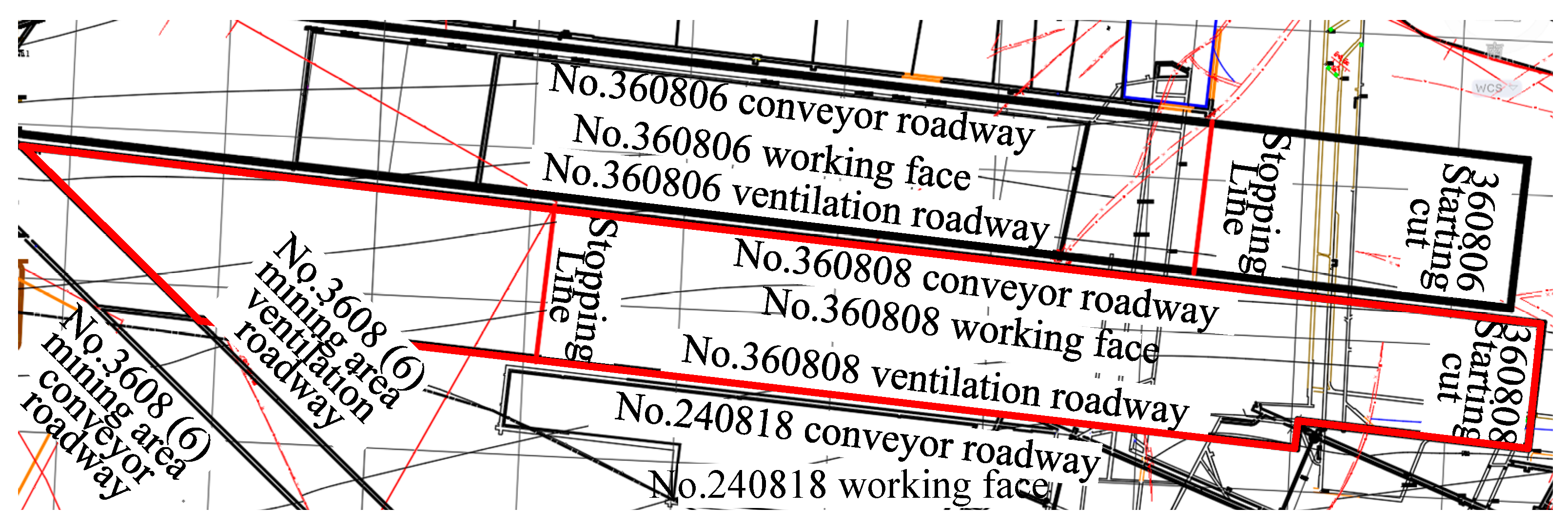
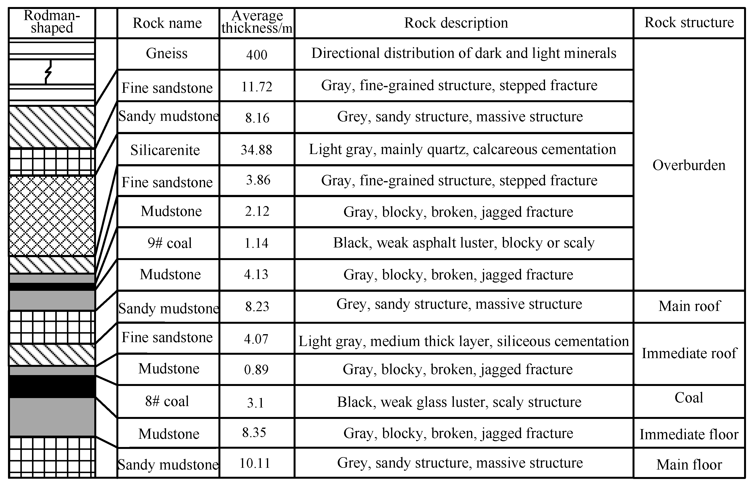
2. Project Overview
- (1)
- Basic information about the working face.
- (2)
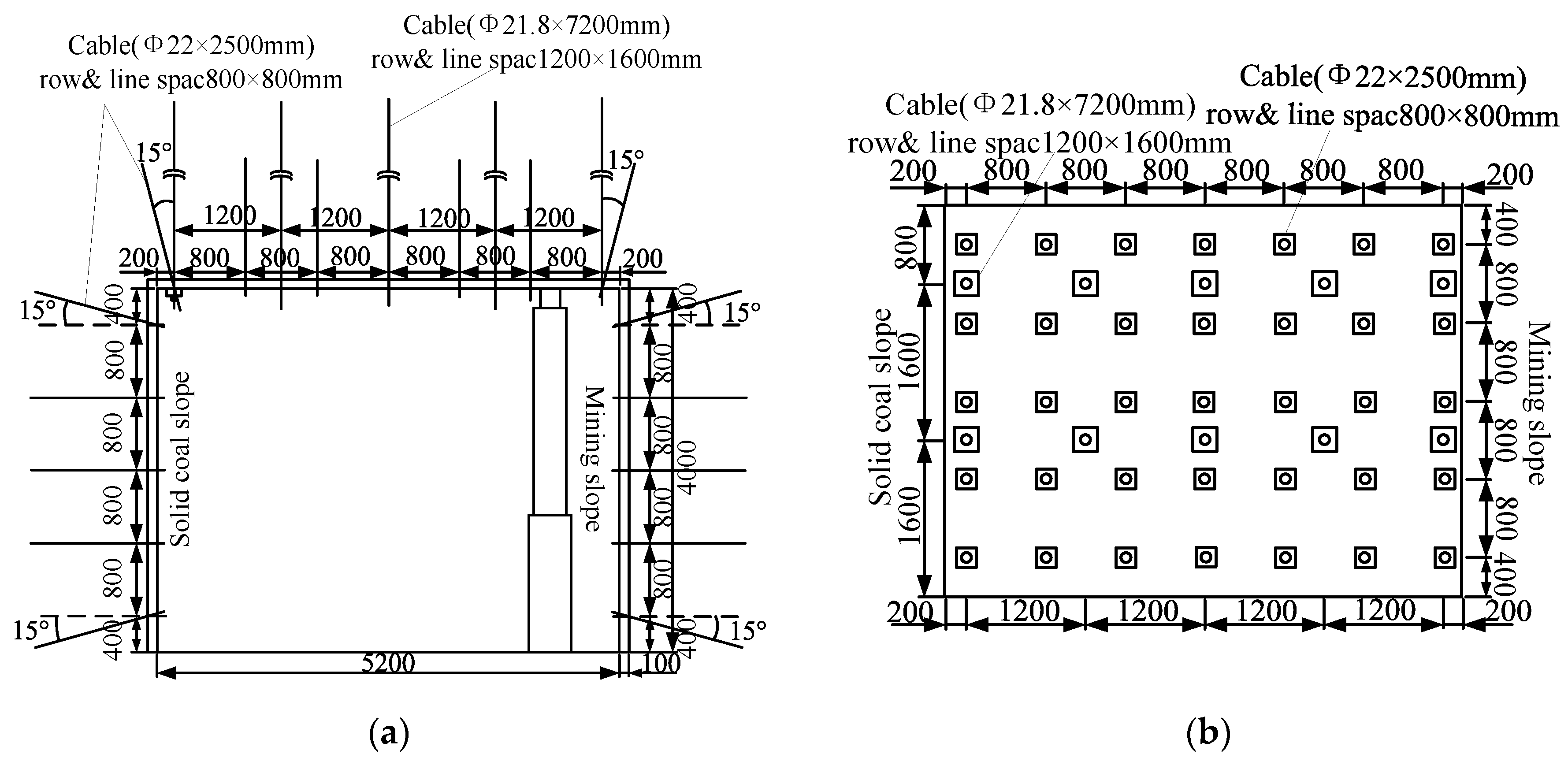
- Design of the original support for the retracement channel.
3. Evolution Law of Deformation and Failure of Surrounding Rock in the Retracement Channel
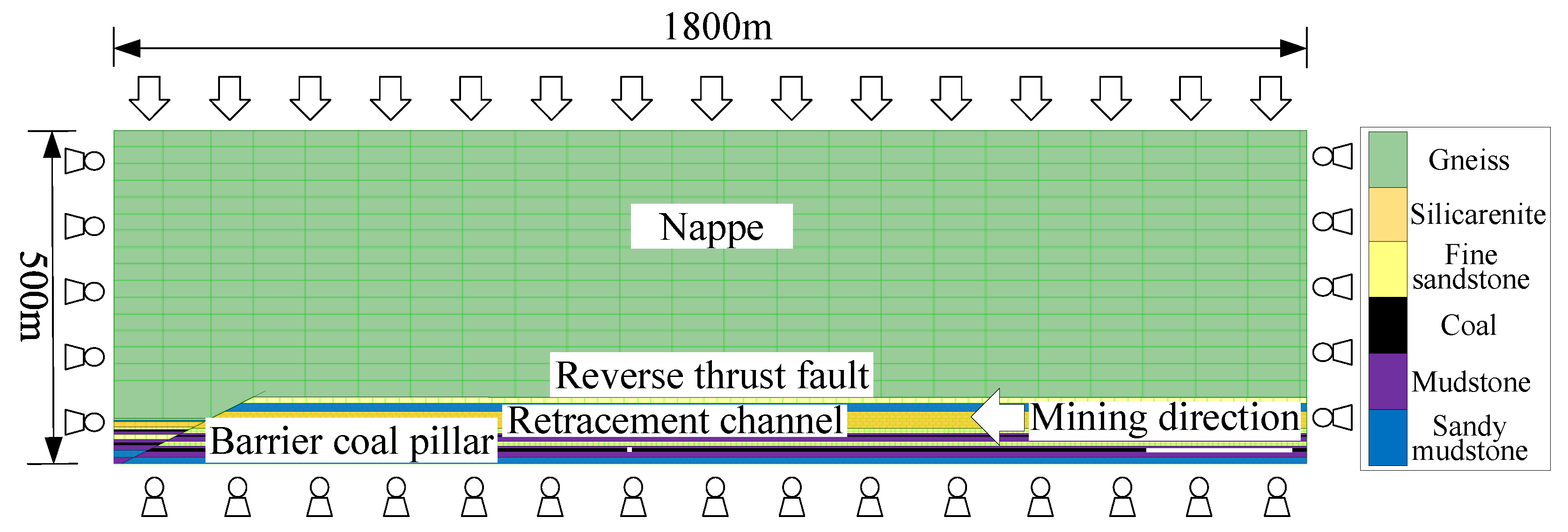
3.1. Numerical Model Establishment and Simulation Plan
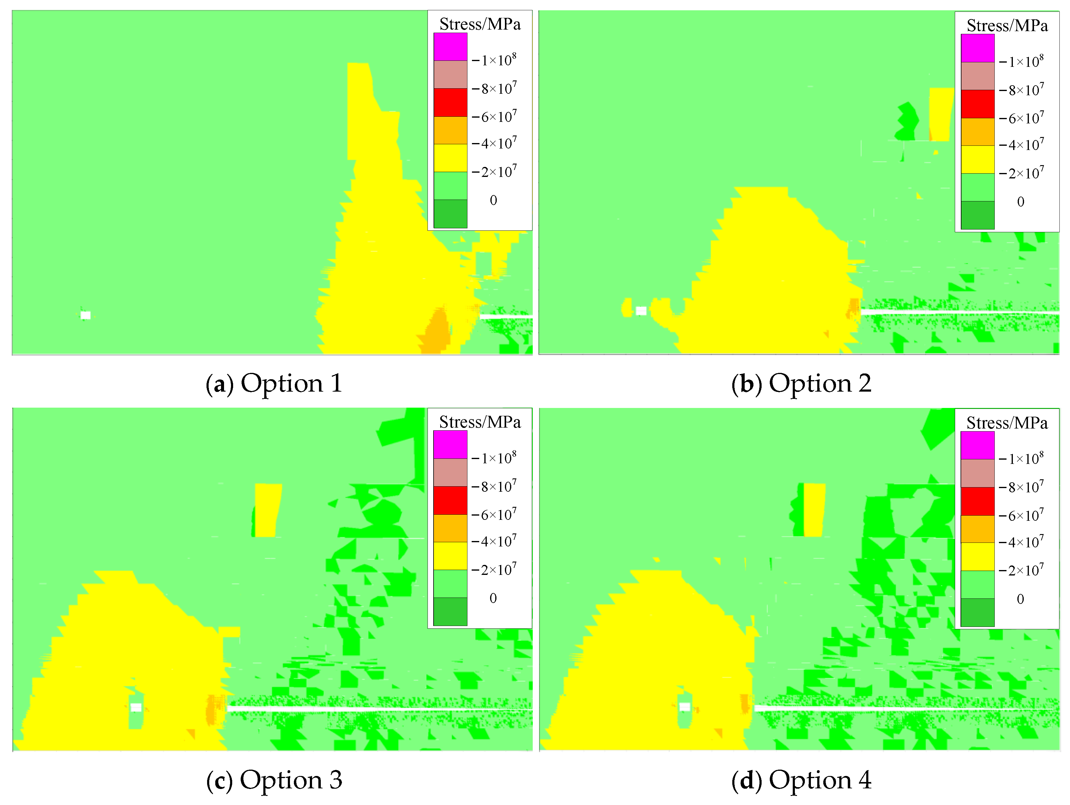
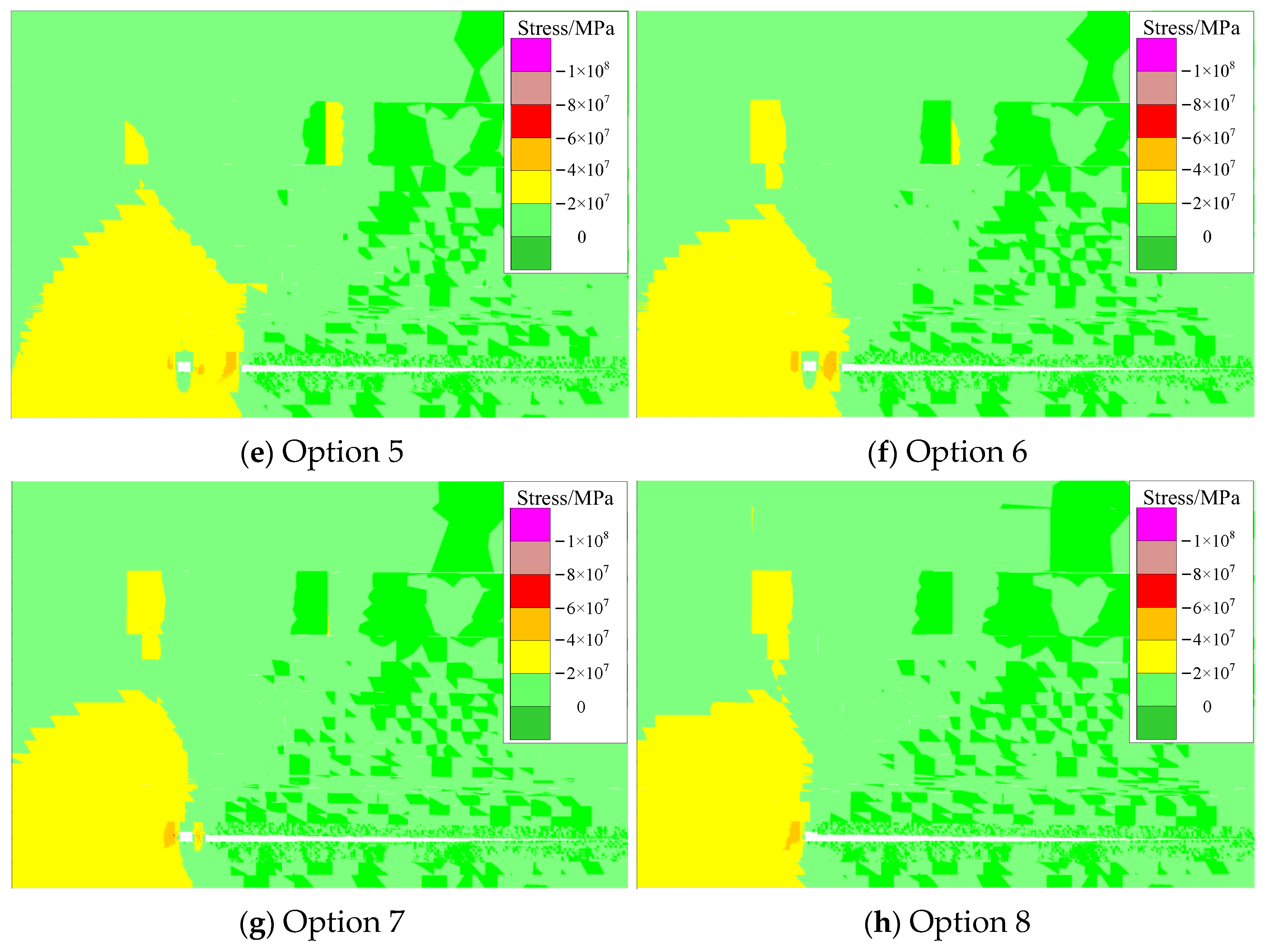
3.2. Stress Distribution and Evolution of Surrounding Rock in the Retracement Channel
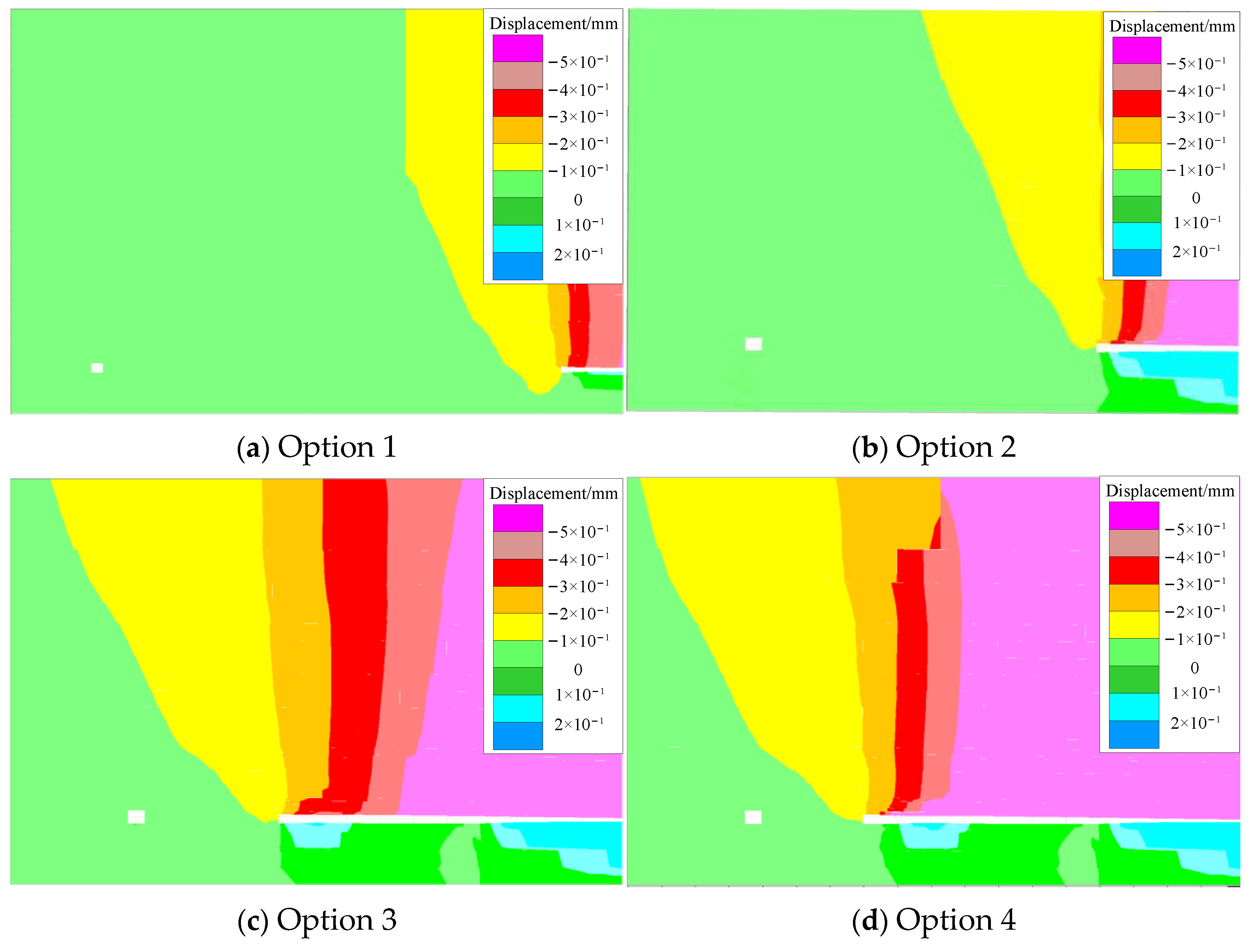
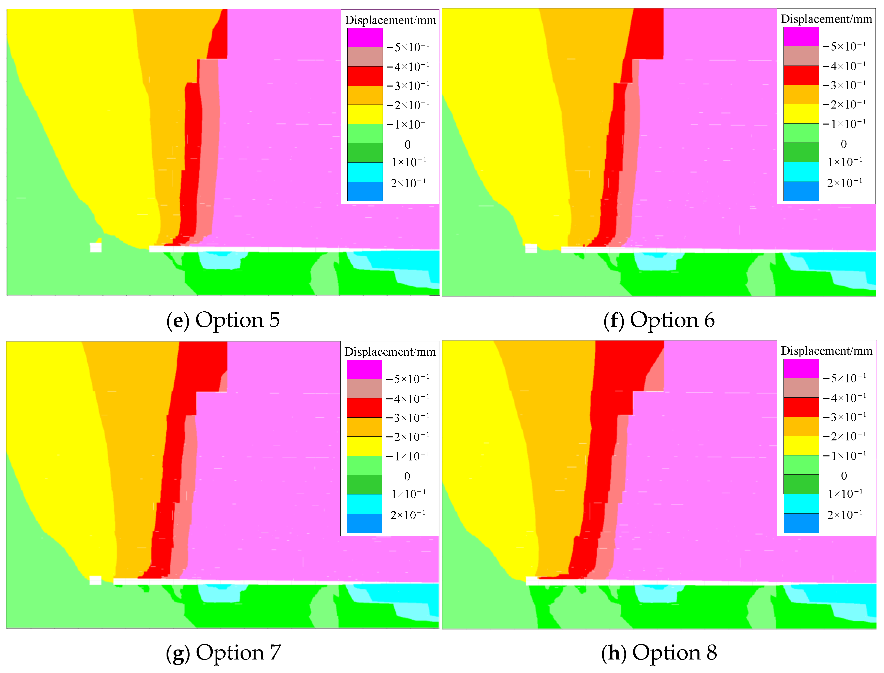
3.3. Deformation and Failure Characteristics of Surrounding Rock in the Retracement Channel
4. Mechanism of Deformation and Failure of Surrounding Rock in the Retracement Channel and Design of Reinforcement Support
4.1. Analysis of the Surrounding Rock Structure of the Retracement Channel
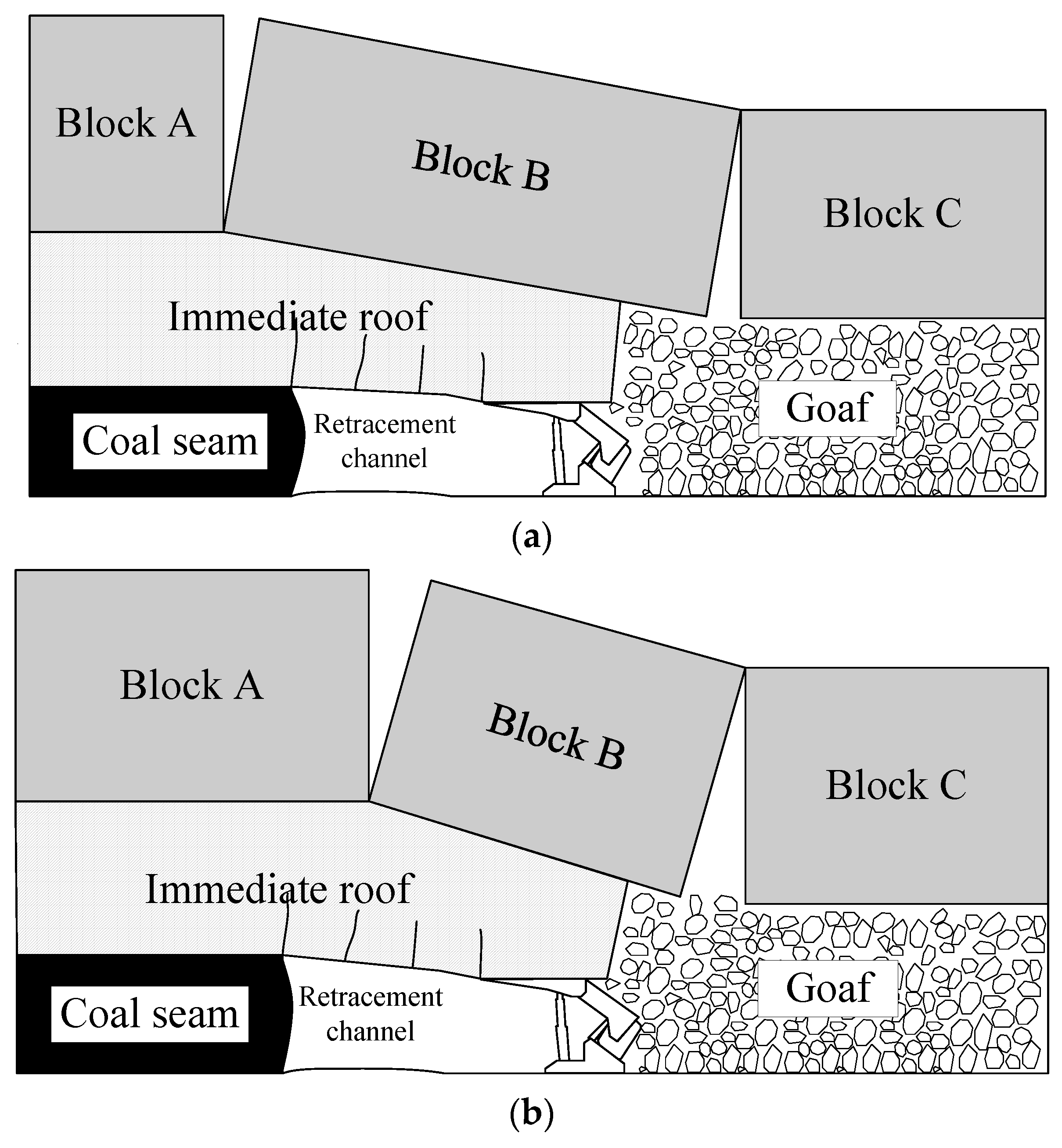
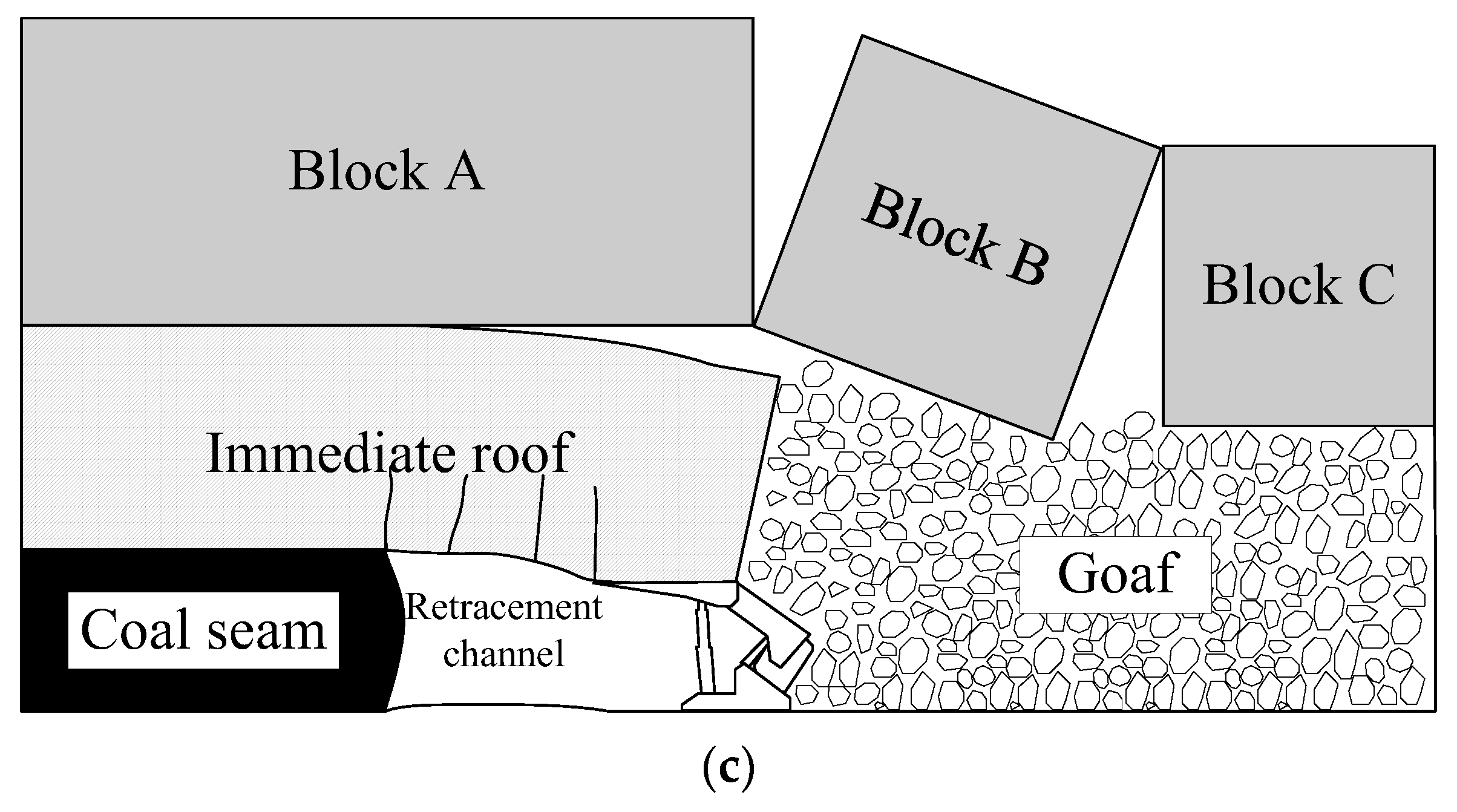
4.1.1. State of the Overburden Structure of the Retracement Channel
4.1.2. Mechanism of Surrounding Rock Failure in the Retracement Channel
- (1)
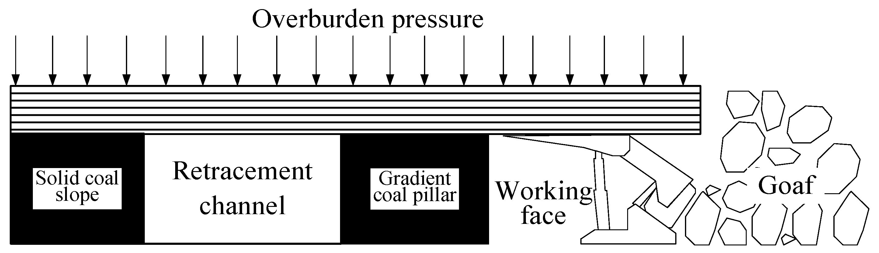
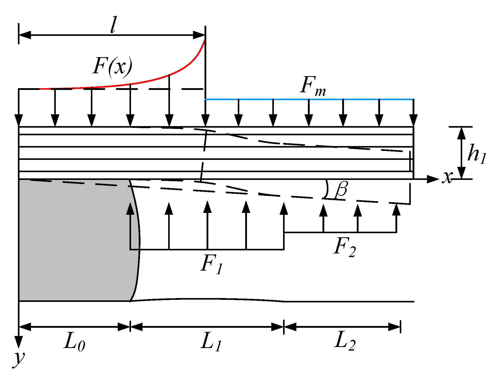
- When the working face is far from the retracement channel, the remaining width of the coal pillar between the working face and the retracement channel is large, and it will not be affected by the mining of the working face. The integrity of the roof and the surrounding rock on the two sides is suitable, and the surrounding rock is in a stable state. During the final mining period, as the working face advances, the width of the interval coal between the working face and the retracement channel continuously decreases, forming a gradually changing width coal pillar. During the connection process between the retracement channel and the working face, there is a significant trend of surrounding rock deformation and stress increase. The gradient coal pillar is affected by the superposition of advanced support pressure and lateral support stress of the retracement channel, and it fails when it exceeds the strength limit. The shallow plastic failure range of the gradient coal pillar expands, as shown in Figure 11.
- (2)
- After the connection between the working face and the retracement channel, the advanced support pressure of the working face begins to transfer to the protective coal pillar outside the retracement channel. The deformation and pressure of the surrounding rock inside the retracement channel both increase sharply, and the roof significantly sinks, expanding the range of solid coal slope fragmentation.
4.2. Construction of Instability Criteria
- (1)
- Main roof key block rotation sinking work.
- (2)
- Work immediately against self-weight.
- (3)
- Work performed by the internal support body of the retracement channel.
- (4)
- Work performed by hydraulic support with cover on the working face.
- (5)
- Strain energy of the solid coal slope of the retracement channel.
- (6)
- Immediate roof strain energy.
4.3. Strengthening Support Strength and Timely Machine Determination
4.3.1. Strengthening Support Strength Design
4.3.2. Timing of Strengthening Support
4.3.3. Strengthening Support Methods
5. Field Practice Verification
5.1. Parameter Analysis and Calculation
5.1.1. Energy Balance Calculation
- (1)
- Calculation of channel support strength under original support conditions.
- (2)
- Calculation of minimum safety support strength.
5.1.2. Strengthening Support Plan
5.2. Analysis of Strengthening Support Effect
5.2.1. Strengthen the On-Site Effect of Support
5.2.2. Analysis of On-Site Monitoring Results
6. Conclusions
- (1)
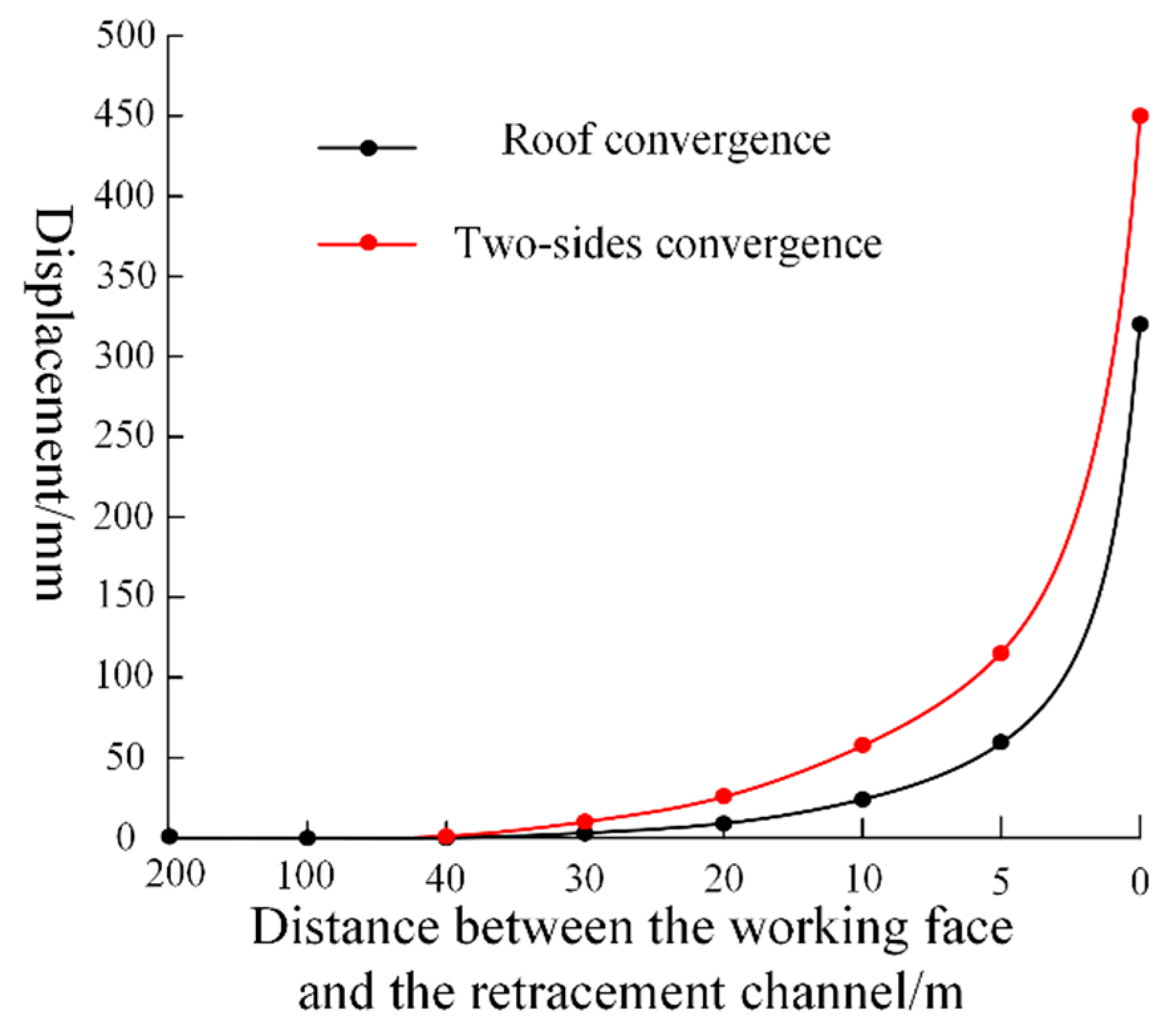
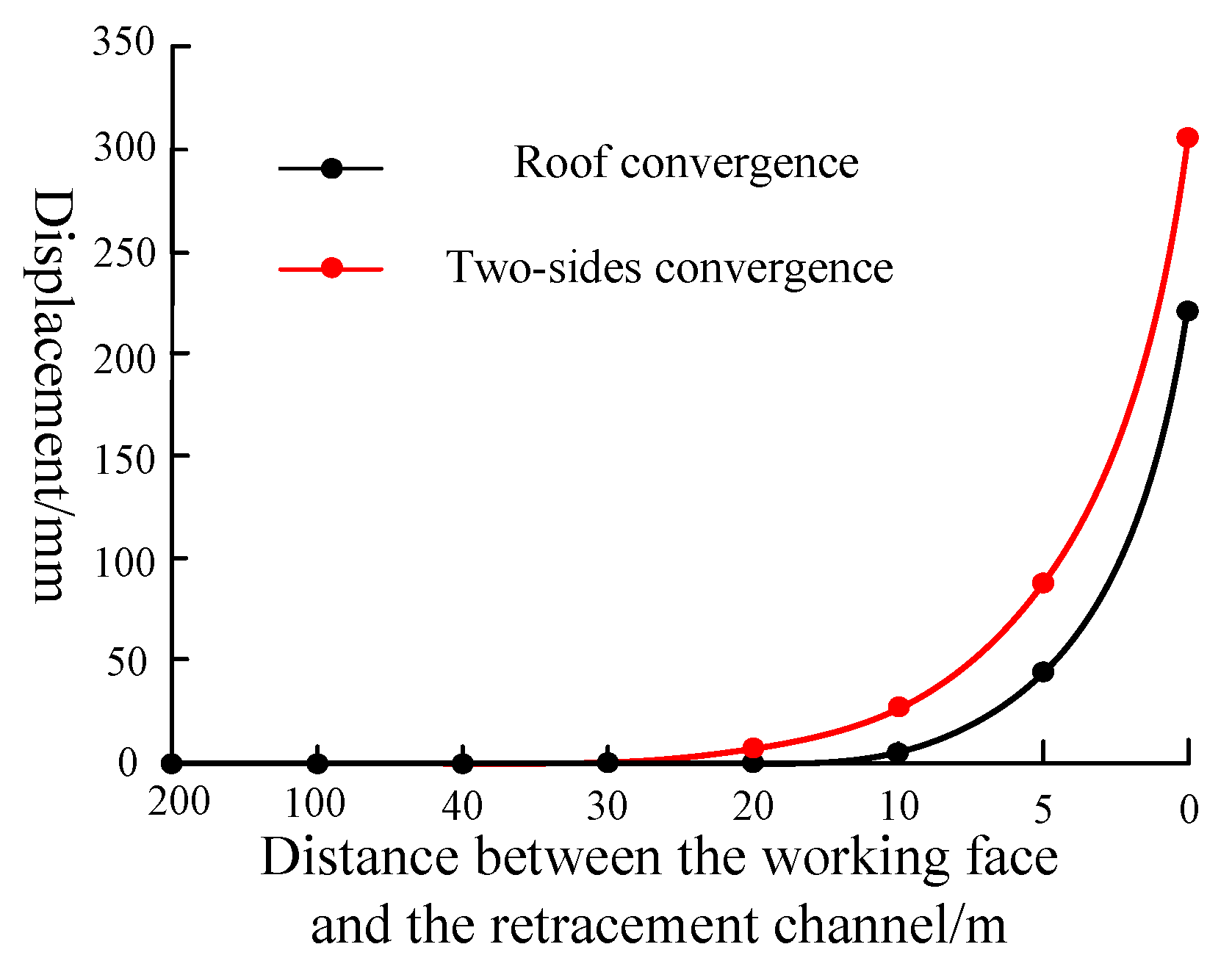
- A gradual excavation model for the working face under the super-thick nappe was established, and the peak stress of the surrounding rock in the retracement channel during the final mining stage was obtained as the mining face continued to increase. It was found that the two sides of the coal pillars in the retracement channel began to exhibit asymmetric deformation characteristics when the width of the gradually changing coal pillars in the working face decreased to 30 m.
- (2)
- A mechanical analysis model of the surrounding rock was established when the basic roof ruptured above the retracement channel. The criterion for instability of surrounding rock was obtained from an energy perspective, and a strengthening support method of adding anchor cables was proposed. The timing for strengthening support was determined to be when the working face was withdrawn to a distance of 15 m from the retracement channel.
- (3)
- Through on-site real-time monitoring, it was found that the numerical simulation results were consistent with the actual situation. After adopting strengthened support, the subsidence of the roof was reduced by 90 mm, and the displacement of the two sides was reduced by 140 mm, both of which met the deformation requirements of the retracement channel. The support effect was significant.
Author Contributions
Funding
Institutional Review Board Statement
Informed Consent Statement
Data Availability Statement
Acknowledgments
Conflicts of Interest
References
- Tan, N.; Yang, R.; Tan, Z. Influence of complicated faults on the differentiation and accumulation of in-situ stress in deep rock mass. Int. J. Miner. Met. Mater. 2023, 30, 791–801. [Google Scholar] [CrossRef]
- Zhang, B.; Zhou, H.; Chang, Q.; Zhao, X.; Sun, Y. The Stability Analysis of Roadway near Faults under Complex High Stress. Adv. Civ. Eng. 2020, 2020, 8893842. [Google Scholar] [CrossRef]
- Li, X.; Liu, X.; Tan, Y.; Chen, A.; Wang, H.; Wang, X.; Yang, S. Rheological mechanical properties and its constitutive relation of soft rock considering influence of clay mineral composition and content. Int. J. Coal Sci. Technol. 2023, 10, 48. [Google Scholar] [CrossRef]
- Xie, S.; Wang, E.; Chen, D.; Li, H.; Jiang, Z.; Yang, H. Stability analysis and control technology of gob-side entry retaining with double roadways by filling with high-water material in gently inclined coal seam. Int. J. Coal Sci. Technol. 2022, 9, 52. [Google Scholar] [CrossRef]
- Shan, R.; Li, Z.; Wang, C.; Wei, Y.; Bai, Y.; Zhao, Y.; Tong, X. Research on the mechanism of asymmetric deformation and stability control of near-fault roadway under the influence of mining. Eng. Fail. Anal. 2021, 127, 105492. [Google Scholar] [CrossRef]
- Yao, N.; Wang, Y.; Yao, Y.; Song, H.; Wang, L.; Peng, T.; Sun, X. Progress of drilling technologies and equipment for complicated geological conditions in underground coal mines in China. Coal Geol. Explor. 2020, 48, 2. [Google Scholar]
- Liu, X.; Song, S.; Tan, Y.; Fan, D.; Ning, J.; Li, X.; Yin, Y. Similar simulation study on the deformation and failure of surrounding rock of a large section chamber group under dynamic loading. Int. J. Min. Sci. Technol. 2021, 31, 495–505. [Google Scholar] [CrossRef]
- Elizalde, C.; Griffith, W.A.; Miller, T. Thrust fault nucleation due to heterogeneous bedding plane slip: Evidence from an Ohio coal mine. Eng. Geol. 2016, 206, 1–17. [Google Scholar] [CrossRef]
- Liu, X.; Fan, D.; Tan, Y.; Ning, J.; Song, S.; Wang, H.; Li, X. New detecting method on the connecting fractured zone above the coal face and a case study. Rock Mech. Rock Eng. 2021, 54, 4379–4391. [Google Scholar] [CrossRef]
- Jiang, F.X.; Wei, Q.D.; Wang, C.W.; Yao, S.L.; Zhang, Y.; Han, R.J.; Wei, X.Z.; Li, Z.C. Analysis of rock burst mechanism in extra-thick coal seam controlled by a huge thick conglomerate and thrust fault. J. China Coal Soc. 2014, 39, 1191–1196. [Google Scholar]
- Gao, X.; Li, Y.; Zhang, Z.; Zhang, Z.; Yu, H.; Huang, Z.; Yue, C. Prevention and control technology of large deformation double active advance blasting pre-cracking roof in soft rock tunnels. J. Coal Ind. 2020, 45 (Suppl. S2), 589–598. [Google Scholar]
- Li, C.; Zhang, Y.; Zhang, G.; Gao, S.; Zhang, H. The stress evolution and crack propagation mechanism of the bottom plate under dynamic disturbance in deep mining. J. Geotech. Eng. 2018, 40, 2031–2040. [Google Scholar]
- Batugin, A.; Wang, Z.; Su, Z.; Sidikovna, S.S. Combined support mechanism of rock bolts and anchor cables for adjacent roadways in the external staggered split-level panel layout. Int. J. Coal Sci. Technol. 2021, 8, 659–673. [Google Scholar] [CrossRef]
- Tan, Y.L.; Fan, D.Y.; Liu, X.S.; Song, S.L.; Li, X.F.; Wang, H.L. Numerical investigation on failure evolution of surrounding rock for super-large section chamber group in deep coal mine. Energy Sci. Eng. 2019, 7, 3124–3146. [Google Scholar] [CrossRef]
- Liu, X.; Fan, D.; Tan, Y.; Song, S.; Li, X.; Ning, J.; Gu, Q.; Ma, Q. Failure evolution and instability mechanism of surrounding rock for close-distance parallel chambers with super-large section in deep coal mines. Int. J. Geomech. 2021, 21, 04021049. [Google Scholar] [CrossRef]
- Wu, Q.; Jiang, L.; Wu, Q. Study on the law of mining stress evolution and fault activation under the influence of normal fault. Acta Geodyn Geomater 2017, 14, 357–369. [Google Scholar] [CrossRef]
- Jiao, Z.; Jiang, Y.; Zhao, Y.; Zhang, M.; Hu, H. Study on the dynamic mechanical response characteristics of working faces passing through faults. J. China Univ. Min. Technol. 2019, 48, 54–63. [Google Scholar]
- Islam, M.R.; Shinjo, R. Mining-induced fault reactivation associated with the main conveyor belt roadway and safety of the Barapukuria coal mine in Bangladesh: Constraints from BEM simulations. Int. J. Coal Geol. 2009, 79, 115–130. [Google Scholar] [CrossRef]
- Li, C.; Guo, X.F.; Huo, T.H.; Liu, R. Coal pillar design of pre-excavated double equipment withdrawal channel and its surrounding rock stability control. J. Huazhong Univ. Sci. Technol. (Nat. Sci. Ed.) 2021, 49, 20–25+31. [Google Scholar]
- Qin, B.; He, F.; Zhang, X.; Xu, X.; Wang, W.; Li, L.; Dou, C. Stability and Control of Retracement Channels in Thin Seam Working Faces with Soft Roof. Shock Vib. 2021, 2021, 8667471. [Google Scholar] [CrossRef]
- Ma, J.; Guan, J.; Duan, J.; Huang, L.; Liang, Y. Stability analysis on tunnels with karst caves using the distinct lattice spring model. Undergr. Space 2021, 6, 469–481. [Google Scholar] [CrossRef]
- Zhang, F.; Cui, L.; An, M.; Elsworth, D.; He, C. Frictional stability of Longmaxi shale gouges and its implication for deep seismic potential in the southeastern Sichuan Basin. Deep Undergr. Sci. Eng. 2022, 1, 3–14. [Google Scholar] [CrossRef]
- Kong, P.; Jiang, L.; Shu, J.; Wang, L. Mining stress distribution and fault-slip behavior: A case study of fault-influenced longwall coal mining. Energies 2019, 12, 2494. [Google Scholar] [CrossRef]
- Han, Z.; Li, D.; Li, X. Dynamic mechanical properties and wave propagation of composite rock-mortar specimens based on SHPB tests. Int. J. Min. Sci. Technol. 2022, 32, 793–806. [Google Scholar] [CrossRef]
- Wu, Y.; Liu, X.; Tan, Y.; Ma, Q.; Fan, D.; Yang, M.; Wang, X.; Li, G. Mechanical Properties and Failure Mechanism of Anchored Bedding Rock Material under Impact Loading. Materials 2022, 15, 6560. [Google Scholar] [CrossRef]
- Luo, S.; Gong, F. Evaluation of rock burst proneness considering specimen shape by storable elastic strain energy. Deep Undergr. Sci. Eng. 2022, 1, 116–130. [Google Scholar] [CrossRef]
- Ji, H.G.; Ma, H.S.; Wang, J.A.; Zhang, Y.H.; Cao, H. Mining disturbance effect and mining arrangements analysis of near-fault mining in high tectonic stress region. Saf. Sci. 2012, 50, 649–654. [Google Scholar] [CrossRef]
- Ma, J.; Zhao, J.; Lin, Y.; Liang, J.; Chen, J.; Chen, W.; Huang, L. Study on Tamped Spherical Detonation-Induced Dynamic Responses of Rock and PMMA Through Mini-chemical Explosion Tests and a Four-Dimensional Lattice Spring Model. Rock Mech. Rock Eng. 2023, 56, 7357–7375. [Google Scholar] [CrossRef]
- Sainoki, A.; Schwartzkopff, A.K.; Jiang, L.; Mitri, H.S. Numerical Modeling of Complex Stress State in a Fault Damage Zone and Its Implication on Near-Fault Seismic Activity. J. Geophys. Res. Solid Earth 2021, 126, e2021JB021784. [Google Scholar] [CrossRef]
- Skrzypkowski, K.; Zagórski, K.; Zagórska, A.; Apel, D.B.; Wang, J.; Xu, H.; Guo, L. Choice of the Arch Yielding Support for the Preparatory Roadway Located near the Fault. Energies 2022, 15, 3774. [Google Scholar] [CrossRef]
- Wang, H.; Shi, R.; Song, J.; Tian, Z.; Deng, D.; Jiang, Y. Mechanical model for the calculation of stress distribution on fault surface during the underground coal seam mining. Int. J. Rock Mech. Min. Sci. 2021, 144, 104765. [Google Scholar] [CrossRef]
- Ma, J.; Chen, J.; Chen, W.; Huang, L. A coupled thermal-elastic-plastic-damage model for concrete subjected to dynamic loading. Int. J. Plast. 2022, 153, 103279. [Google Scholar] [CrossRef]
- Zhang, S.; Xu, X.; Zhao, X.; Zhou, X.; Huang, P. Study on excavation unloading; rheology and supporting time of soft rock in deep buried cavern. J. China Three Gorges Univ. (Nat. Sci.) 2020, 42, 57–62. [Google Scholar]
- Dokht, R.M.; Smith, B.; Kao, H.; Visser, R.; Hutchinson, J. Reactivation of an intraplate fault by mine-blasting events: Implications to regional seismic hazard in Western Canada. J. Geophys. Res. Solid Earth 2020, 125, e2020JB019933. [Google Scholar] [CrossRef]
- Li, Z.; Wang, C.; Shan, R.; Yuan, H.; Zhao, Y.; Wei, Y. Study on the influence of the fault dip angle on the stress evolution and slip risk of normal faults in mining. Bull. Eng. Geol. Environ. 2021, 80, 3537–3551. [Google Scholar] [CrossRef]
- Chen, X.; Li, W.; Yan, X. Analysis on rock burst danger when fully-mechanized caving coal face passed fault with deep mining. Saf. Sci. 2012, 50, 645–648. [Google Scholar] [CrossRef]
- Wu, Q.; Wu, Q.; Yuan, A.; Wu, Y. Analysis of mining effect and fault stability under the influence of normal faults. Geotech. Geol. Eng. 2021, 39, 49–63. [Google Scholar] [CrossRef]
- Gu, S.C.; Wang, B.N.; Huang, R.B.; Miao, Y. Method for determining the load on and width of coal pillar at the recovery room end of fully-mechanized longwall mining. J. China Univ. Min. Technol. 2015, 44, 990–995. [Google Scholar]
- Zhu, R.; Yue, X.; Liu, X.; Shi, Z.; Li, X. Study on Influencing Factors of Ground Pressure Behavior in Roadway-Concentrated Areas under Super-Thick Nappe. Materials 2023, 16, 89. [Google Scholar] [CrossRef] [PubMed]
- Jiao, Z.; Wang, L.; Zhang, M.; Wang, J. Numerical Simulation of Mining-Induced Stress Evolution and Fault Slip Behavior in Deep Mining. Adv. Mater. Sci. Eng. 2021, 2021, 8276408. [Google Scholar] [CrossRef]
- Yang, S.Q.; Chen, M.; Jing, H.W.; Chen, K.F.; Meng, B. A case study on large deformation failure mechanism of deep soft rock roadway in Xin’An coal mine, China. Eng. Geol. 2017, 217, 89–101. [Google Scholar] [CrossRef]
- Yan, S.; Zhang, D.; Bai, J.; Guo, Y. Research on the Stability of Surrounding Rock and Active Passive Joint Control Technology in the Retraction Tunnel. J. Min. Saf. Eng. 2023, 40, 774–785. [Google Scholar]
- Wang, B. Research on the Deformation and Failure Mechanism of Surrounding Rock in the Retraction Tunnel and Its Control Technology. Ph.D. Thesis, Xi’an University of Science and Technology, Xi’an, China, 2017. [Google Scholar]
- Fan, D.; Liu, X.; Tan, Y.; Li, X.; Lkhamsuren, P. Instability energy mechanism of super-large section crossing chambers in deep coal mines. Int. J. Min. Sci. Technol. 2022, 32, 1075–1086. [Google Scholar] [CrossRef]
- Zhang, D.; Duan, Y.; Du, W.; Chai, J. Experimental Study on Physical Similar Model of Fault Activation Law Based on Distributed Optical Fiber Monitoring. Shock Vib. 2021, 2021, 4846977. [Google Scholar] [CrossRef]
- Wang, H.; Jiang, Y.; Xue, S.; Mao, L.; Lin, Z.; Deng, D.; Zhang, D. Influence of fault slip on mining-induced pressure and optimization of roadway support design in fault-influenced zone. J. Rock Mech. Geotech. Eng. 2016, 8, 660–671. [Google Scholar] [CrossRef]
- Liu, X.; Wu, Y.; Tan, Y.; Yang, M.; Li, G.; Xie, C. Mechanism of inclined anchor rod fracture and timing of strengthening support in deep high-level stress tunnels. J. Coal Ind. 2023, 48, 609–622. [Google Scholar]
- Yalong, L.; Ahmed, M.A.; Cheng, L. Support design of main retracement passage in fully mechanised coal mining face based on numerical simulation. Appl. Math. Nonlinear Sci. 2021, 7, 553–560. [Google Scholar]
- Jin, Y.; Geng, J.; Lv, C.; Chi, Y.; Zhao, T. A methodology for equipment condition simulation and maintenance threshold optimization oriented to the influence of multiple events. Reliab. Eng. Syst. Saf. 2023, 229, 108879. [Google Scholar] [CrossRef]


| Serial Number | Rock Name | Thickness/m | Density kg/m3 | Tensile Strength/MPa | Elastic Modulus/GPa | Cohesion/MPa | The Angle of Internal Friction/° | Poisson Ratio |
|---|---|---|---|---|---|---|---|---|
| 1 | Gneiss | 400 | 2763 | 11.2 | 44.8 | 15 | 40 | 0.25 |
| 2 | Fine sandstone | 12 | 2532 | 5.38 | 37.15 | 3.2 | 42 | 0.27 |
| 3 | Sandy mudstone | 8 | 2562 | 2.6 | 12.08 | 2.45 | 40 | 0.25 |
| 4 | Silicarenite | 35 | 2423 | 4.9 | 21.75 | 21 | 75 | 0.29 |
| 5 | Fine sandstone | 4 | 2532 | 5.38 | 37.15 | 3.2 | 42 | 0.27 |
| 6 | Mudstone | 2 | 2582 | 2.0 | 10.37 | 1.2 | 32 | 0.28 |
| 7 | No. 9 coal seam | 1 | 1401 | 0.3 | 2.79 | 0.8 | 29 | 0.32 |
| 8 | Mudstone | 4 | 2582 | 2.0 | 10.37 | 1.2 | 32 | 0.28 |
| 9 | Sandy mudstone | 8 | 2562 | 2.6 | 12.08 | 2.45 | 40 | 0.25 |
| 10 | Fine sandstone | 4 | 2532 | 5.38 | 37.15 | 3.2 | 42 | 0.27 |
| 11 | Mudstone | 1 | 2582 | 2.0 | 10.37 | 1.2 | 32 | 0.28 |
| 12 | No. 8 coal seam | 3 | 1378 | 0.4 | 1.32 | 0.8 | 29 | 0.31 |
| 13 | Mudstone | 8 | 2582 | 2.0 | 10.37 | 1.2 | 32 | 0.28 |
| 14 | Sandy mudstone | 10 | 2562 | 2.6 | 12.08 | 2.45 | 40 | 0.25 |
| Simulation Scheme | One | Two | Three | Four | Five | Six | Seven | Eight |
|---|---|---|---|---|---|---|---|---|
| Excavation length/m | 800 | 100 | 60 | 10 | 10 | 10 | 5 | 5 |
| Interval length from retreat channel/m | 200 | 100 | 40 | 30 | 20 | 10 | 5 | 0 |
Disclaimer/Publisher’s Note: The statements, opinions and data contained in all publications are solely those of the individual author(s) and contributor(s) and not of MDPI and/or the editor(s). MDPI and/or the editor(s) disclaim responsibility for any injury to people or property resulting from any ideas, methods, instructions or products referred to in the content. |
© 2023 by the authors. Licensee MDPI, Basel, Switzerland. This article is an open access article distributed under the terms and conditions of the Creative Commons Attribution (CC BY) license (https://creativecommons.org/licenses/by/4.0/).
Share and Cite
Zhu, R.; Yue, X.; Gao, Y.; Liu, X.; Li, X.; Xie, C.; Wang, K. Study on the Stress Evolution and Strengthening Support Timing of the Retracement Channel under the Super-Thick Nappe. Sustainability 2023, 15, 15677. https://doi.org/10.3390/su152115677
Zhu R, Yue X, Gao Y, Liu X, Li X, Xie C, Wang K. Study on the Stress Evolution and Strengthening Support Timing of the Retracement Channel under the Super-Thick Nappe. Sustainability. 2023; 15(21):15677. https://doi.org/10.3390/su152115677
Chicago/Turabian StyleZhu, Ruojun, Xizhan Yue, Yudong Gao, Xuesheng Liu, Xuebin Li, Chengcheng Xie, and Kun Wang. 2023. "Study on the Stress Evolution and Strengthening Support Timing of the Retracement Channel under the Super-Thick Nappe" Sustainability 15, no. 21: 15677. https://doi.org/10.3390/su152115677
APA StyleZhu, R., Yue, X., Gao, Y., Liu, X., Li, X., Xie, C., & Wang, K. (2023). Study on the Stress Evolution and Strengthening Support Timing of the Retracement Channel under the Super-Thick Nappe. Sustainability, 15(21), 15677. https://doi.org/10.3390/su152115677