Article

Distributed Control Scheme for Clusters of Power Quality Compensators in Grid-Tied AC Microgrids

by
Manuel Martínez-Gómez
1,2,3,*,
Claudio Burgos-Mellado
3,
Helmo Kelis Morales-Paredes
4,
Juan Sebastián Gómez
5,
Anant Kumar Verma
3 and
Jakson Paulo Bonaldo
6
1
Electrical Engineering Department, Universidad de Chile, Santiago 8370451, Chile
2
Power Electronics, Machines and Control Group (PEMC), University of Nottingham, Nottingham NG7 2R, UK
3
Electric Power Conversion Systems Laboratory (SCoPE Lab), Institute of Engineering Sciences, Universidad de O’Higgins, Rancagua 2841959, Chile
4
Institute of Science and Technology of Sorocaba, São Paulo State University (UNESP), Av. Três de Março 511, Sorocaba 18087-180, Brazil
5
Energy Transformation Center, Engineering Faculty, Universidad Andres Bello, Santiago 7500971, Chile
6
Department of Electrical Engineering, Federal University of Mato Grosso (UFMT), Cuiabá 78060-900, Brazil
*
Author to whom correspondence should be addressed.
Sustainability 2023, 15(22), 15698; https://doi.org/10.3390/su152215698
Submission received: 28 August 2023 / Revised: 24 October 2023 / Accepted: 2 November 2023 / Published: 7 November 2023
(This article belongs to the Special Issue Applications and Advanced Control of Microgrids)

Abstract

:
Modern electrical systems are required to provide increasing standards of power quality, so converters in microgrids need to cooperate to accomplish the requirements efficiently in terms of costs and energy. Currently, power quality compensators (PQCs) are deployed individually, with no capacity to support distant nodes. Motivated by this, this paper proposes a consensus-based scheme, augmented by the conservative power theory (CPT), for controlling clusters of PQCs aiming to improve the imbalance, harmonics and the power factor at multiple nodes of a grid-tied AC microgrid. The CPT calculates the current components that need to be compensated at the point of common coupling (PCC) and local nodes; then, compensations are implemented by using each grid-following converter’s remaining volt-ampere capacity, converting them in PQCs and improving the system’s efficiency. The proposal yields the non-active power balancing among PQCs compounding a cluster. Constraints of cumulative non-active contribution and maximum disposable power are included in each controller. Also, grid-support components are calculated locally based on shared information from the PCC. Extensive simulations show a seamless compensation (even with time delays) of unbalanced and harmonics current (below 20% each) at selected buses, with control convergences of 0.5–1.5 [s] within clusters and 1.0–3.0 [s] for multi-cluster cooperation.

1. Introduction

In recent years, there has been a growing interest in protecting the environment and promoting energy sustainability. As a result, research has focused on finding alternative sources of renewable energy to replace the use of fossil fuels. The integration of distributed non-conventional renewable energy (NCRE) sources into the electrical grid can be realized by means of the microgrid (MG) concept, which combines local generation, energy storage, and loads for an autonomous operation [1,2,3,4]. This integration is enabled by power electronic converters in charge of interfacing the NCRE distributed generation units with the MG. Note that MGs have two operating conditions: (i) connected to the main grid (grid-tied) and (ii) disconnected to the main power grid (isolated) [1,3].
Focusing on grid-tied MGs, the control over the power converters is implemented using a grid-following (grid-feeding) mode, meaning a behaviour approximate to a current source. In this sense, grid-follower converters provide power based on energy harvesting from the distributed NCRE sources [3]. Due to the variability of natural resources, it is expected that the nominal capacity of power converters is not fully used for long periods. It is worth noting that in grid-tied systems, in case of need, power quality compensation can seemingly be supplied by the grid-following converters due to the fact that the grid can support the MG’s active power consumption [5,6,7].
Considering the intermittency of generators and the fact that MGs are inherently unbalanced and distorted electrical systems—which is heightened when small and low-voltage (LV) distribution systems are considered—the power quality observed in MGs could advance the ageing of electrical/electronic devices connected to them [4,5]. Indeed, for LV MGs, imbalance and harmonics issues must be considered and properly managed to ensure a reliable and safe operation. For instance, in an unbalanced MG operation, there are (i) oscillations in the converter’s DC-link, (ii) circulation of a neutral current through the neutral wire for three-phase four-wire MGs (the one considered in this paper) [8], and (iii) a double-frequency oscillating active power component if synchronous or a doubly fed induction generator-based micro-generator is part of the MG [5]. This double frequency translates into an oscillating torque component in these generators, producing mechanical stress, torque pulsations and noise, affecting the efficiency and life span of these machines. Harmonic issues can (i) produce harmonic interaction and harmonic resonance between the inverters and the network, (ii) produce harmonics that contribute to decreasing the maximum load which can be drawn from NCRE generation units, and (iii) since an MG is a weak system, harmonic loads could produce harmonic voltages, which could spread through the system [8].
It is expected that future power grids could cope with power demands while maintaining system power quality. Therefore, there is a need for technical solutions that take advantage of existing infrastructure and equipment, like power converters, to achieve the MG operational goal cost effectively. In the next subsection, to offer a background on which this paper bases its proposal, a summary of related works using power converters in MGs for power quality compensation is presented.

1.1. Literature Review

To address the imbalance and harmonic issues described above, various technologies have been deployed in the last decade which commonly rely on power converters used as part of the distributed flexible AC transmission system (DFACTS) family [4,5,8]; the DFACTS are distributed across the MG to provide support at specific points. Inside DFACTSs, two major technologies are preferred, namely the shunt active power filter (SAPF)—for harmonic and imbalance compensations—and the static synchronous compensator (STATCOM)—for reactive power compensations [8]. The control objectives commonly include compensating current imbalance and harmonics while managing the reactive power at specific points of a grid-tied MG system. For this, the use of dedicated power quality compensators (PQCs) based on a combination of SAPFs and STATCOMs is a valid option explored by many authors in the literature, such as in [6,9,10,11]. However, these early solutions require additional hardware in the system, increasing costs. For example, in reference [11], the harmonic distortion of the current at the PCC is reduced by a coordinated allocation strategy of APFs. The proportional distribution of harmonic compensation is performed by a central controller, which estimates weighting parameters using average values of the current and estimated harmonic compensation rates.
Some approaches have proposed using high power units to perform power quality compensations [12,13]. Recent examples in the literature are [6], in which multiple interconnected converters are used, and [14], in which a modular multilevel converter is used; both methods reduce the number of required devices spread on the MG (simplifying the communication network). Nevertheless, this kind of approach usually requires complex construction topologies, which are not exempt from control difficulties and elevated production costs.
To overcome these cost issues, the authors of [7,15,16,17,18] propose a cost-effective solution that embeds compensation functionalities on the control system of power converters already installed in the MG, maximizing hardware utilization. For instance, in [15], a control scheme for SAPFs in a smart grid is proposed. The control scheme aims to improve the power quality at the point of common coupling (PCC) (in terms of imbalances and harmonics) by coordinating the compensation effort of the SAPFs present in the system; also, a centralized controller is in charge of calculating the compensation effort for each SAPF. A similar approach is proposed in [17] for MG applications. The control system is based on a multi-primary–secondary architecture, where the primary converter regulates both the voltage and the frequency of the system and the secondary converters act as grid-following converters; a supervisory control system calculates the current reference for the latter converters. In reference [7], a two-layer optimization model was recently proposed for the allocation of active power injection and harmonic mitigation of multi-functional inverters. The model is solved by particle swarm optimization relying on centralized communications, and it can achieve both an economical operation and the mitigation of undesired harmonic levels.
It is worth remembering that proposals [7,15,16,17,18] are based on a centralized control approach. However, as discussed in [2,19], the distributed approach has advantages over the centralized approach: better reliability, flexibility, scalability, plug-and-play operation, and tolerance to single-point failures. We note that consensus-based distributed control schemes have been widely used for power converters in grid-forming isolated MGs operating under droop control schemes [2]; however, this approach has been little explored in the literature for grid-follower converters.
Regarding the compensation over multiple buses in an MG, works [20,21,22,23,24] address this topic. In [20], a decentralized local compensation scheme is developed in each converter (i.e., PQC) at sub-buses to reduce the current harmonic propagation to the MG’s PCC. However, with this decentralized approach, the DGs cannot support the harmonic compensation at other buses, like the PCC. Therefore, it is clear that better performance could be achieved via cooperation/coordination between clusters of PQCs using centralized or distributed approaches to support selected buses. In [21], the authors explore an optimization scheme for compensating harmonics in multiple buses using a single SAPF. The controller relies on a model predictive optimizer applied on a two-bus shipboard isolated MG. The approach requires a fixed MG topology, and its application in a large system with plug-and-play generators is not practical to realize. In reference [22], a cooperative control scheme for power electronic converters in an MG is addressed using information received from local loads and neighbouring units. Notably, consensus terms for stationary and oscillatory power components are used to mitigate imbalances and harmonics at local nodes and the PCC. Consequently, the aforementioned methodology allows for an effective compensation but without choosing individual levels of harmonic distortion, reactive power, and current imbalance. Finally, in reference [23], an optimal installation of SAPFs is proposed, where comprehensive harmonic mitigation in a distribution network can be achieved. A model of SAPF with extended-range compensation is developed to assess the distance and sensitivity of harmonic compensation for harmonic disturbance sources across multiple buses. The optimization problem is solved using a centralized control. However, the model requires knowledge of the system’s harmonic impedance matrix and makes assumptions that may not be accurate in real-time operations with plug-and-play loads.

1.2. Contributions

Motivated by the above discussion, this paper proposes a novel distributed control scheme based on the consensus theory [2] and augmented by the conservative power theory (CPT) [25] to improve the power quality of grid-connected MGs. The proposed control scheme uses the remaining volt-ampere (VA) power capacity of multi-functional power converters for compensating imbalances and harmonics at some critical nodes of the MG. The consensus control requires low bandwidth communications, so it is a low-cost investment compatible with any existing infrastructure. Also, due to its distributed nature, the proposed control scheme does not require a central controller, unlike the models previously reported in papers in this area [7,15,16,17,18].
The use of CPT allows the decomposition of the power in independent current and voltage components, which represent reactivity, distortion and imbalance. This provides a feasible instrument for delivering significant data in real-world MG operational scenarios. CPT is appealing for integrating auxiliary features in grid-tied inverters because of its ability to characterize the load under imperfect voltage conditions (such as distorted or unbalanced voltages), as shown in [15,26]. Further, it offers the selectivity and the adaptability to generate reference currents without requiring coordinate transformations or the implementation of any synchronization algorithms [27]. This means that with the proposed control protocol, accurate current compensations could be made without using Delayed Signal Cancellation (DSC) [27,28,29] or other methods, which are highly susceptible to noise. Furthermore, CPT is versatile and can be used in a variety of systems, regardless of the number of phases and conductors.
For compensation over multiple buses, groups of PQCs, physically close to each other, are considered. Unlike individual PQCs per bus, a cluster of PQCs allows compensation of higher powers by combining the capacity of multiple PQCs [11,17]. Thus, a cluster of PQCs could be viewed as an alternative to high-power FACTS (like multi-level topologies [12]). It is important to note that the PQC’s cluster approach does not necessarily require all hardware to be located in the same physical place.
To the best of the authors’ knowledge, regarding consensus algorithms for the coordination of CPT-based converters in grid-tied MGs, conference papers [22,30] published recently by some of the authors of this proposal are the pioneers in addressing this topic. In this sense, the current proposal corresponds to an extension of [30] since it addresses some of its limitations and develops a more general approach. Indeed, the control scheme reported in [30] requires the initial conditions of the grid-following converters to be known before its activation, hindering its application to real systems. This is avoided in the new proposed control scheme by using novel distributed consensus observers to estimate such initial conditions. In addition, in contrast to [30], where a single-bus MG topology was addressed, this paper follows the topological guidelines of [22] and thereafter extends the proposal to operate in multiple buses. Similar to [22], this proposal controls the PQCs in a distributed fashion. However, in this work, multiple clusters of PQCs are controlled and coordinated in a distributed fashion using the CPT approach.
The features of the proposed control strategy are highlighted in a comparative table regarding the published literature as shown below (Table 1).
The contributions of this work are summarized as follows:
  • A distributed control protocol using the CPT for non-active power-sharing in a cluster of parallel PQCs connected to a grid-tied MG is proposed. This protocol allocates the contributions of the converters concerning the per-unit (p.u.) available power.
  • A new observer-based control loop for controlling the sharing of compensations for non-active power in a PQC cluster is presented. Also, a stability analysis is included.
  • A cooperative multi-purpose control scheme for current imbalance and harmonics in multiple buses is described. Each cluster of PQC performs a local and a grid-side compensation using the CPT framework.
  • Online regulation via adjusted weights for the trade-off between grid-side and local CPT current components compensations is presented. The weights are adjusted according to deviations in defined power quality factors.
The rest of the paper is organized as follows: Section 2 presents preliminaries about CPT and graph theory. Section 3 describes the design of the cooperative control of PQCs in a cluster. Section 4 explains the multi-purpose control scheme between the clusters of PQCs considering the trade-off regulations of local and grid-side compensations. Section 5 describes the methodology for simulation analysis. Section 6 demonstrates the results and discussions. Finally, conclusions are presented in Section 7.

2. Preliminaries

The notation of bold letters in equations stands for vectors. Also, whenever possible, capitalized letters in equations represent matrices or RMS magnitudes.

2.1. Conservative Power Theory

The instantaneous quantities in a three-phase system can be defined for any phase voltage (v) and current (i) waveforms as
p ( t ) = v ( t ) i ( t ) = v a ( t ) i a ( t ) + v b ( t ) i b ( t ) + v c ( t ) i c ( t ) , w ( t ) = v ^ ( t ) i ( t ) = v ^ a ( t ) i a ( t ) + v ^ b ( t ) i b ( t ) + v ^ c ( t ) i c ( t ) ,
where p ( t ) and w ( t ) are the instantaneous active power and reactive energy, respectively. The term v ^ is the unbiased phase voltage integral (i.e., phase voltage integral without DC component). It was shown [25] that p ( t ) and w ( t ) are conservative for every network, irrespective of voltage and current waveforms.
Remark 1. 
For the sake of simplicity, all of the time dependencies of variables are omitted here and on for the rest of the article (e.g., v a ( t ) = v a ).
The corresponding average terms of (1) are
P = v , i = 1 T 0 T ( v i ) d t = 1 T 0 T ( v a i a + v b i b + v c i c ) d t , W = v ^ , i = 1 T 0 T ( v ^ i ) d t = 1 T 0 T ( v ^ a i a + v ^ b i b + v ^ c i c ) d t ,
where P and W are the active power and reactive energy. Based on (2), the current of a generic three-phase power system can be characterized with orthogonal components as follows [25]:
i = i a b + i r b + i u + i v = i a b + i NA ,
where i a b and i r b are the active and reactive balanced current components, i u and i v are the unbalanced and void (distorted) current components, and i NA are the non-active currents.
As the components of (3) are orthogonal to each other, the estimation of the RMS collective value (norm) of the current results in the following equation:
I = ( i a , RMS b ) 2 + ( i r , RMS b ) 2 + ( i u , RMS ) 2 + ( i v , RMS ) 2 = ( I a b ) 2 + ( I r b ) 2 + ( I u ) 2 + ( I v ) 2 = ( I a b ) 2 + ( I NA ) 2 ,
where I a b , I r b , I u , I v and I NA are the RMS collective values of the current components.
Therefore, the apparent power, S, can be estimated using (4) as
S = V I = V ( I a b ) 2 + ( I r b ) 2 + ( I u ) 2 + ( I v ) 2 = P 2 + Q 2 + U 2 + D 2 = P 2 + NA 2 ,
where V = V a 2 + V b 2 + V c 2 is the RMS collective value of the voltage, P = V I a b is the active power, Q = V I r b is the reactive power, U = V I u is the unbalance power, D = V I v is the void (distortion) power and NA = V I NA is the non-active power.

2.2. Graph Theory

A distributed and bidirectional communication network of a multi-agent system can be modelled as an undirected graph G ( N , ξ , A ) among agents N = { 1 , , N } , where ξ is the set of communication links and A is the non-negative N × N weighted adjacency matrix. The elements of A can be assigned as binary values such that
a i j = 1 if data from agent j arrives at agent i , i j 0 otherwise .
We let x i R be the value of some quantity of interest at node i; it is said that the multi-agent system achieves consensus if and only if [ x j x i ] 0 as t i , j N . Then, the consensus of a first-order multi-agent system can be achieved via the consensus protocol
x ˙ i = c j N i a i j · x j x i ,
where c is the coupling gain regulating the convergence speed [19]. It is worth to highlight that the consensus is achieved if and only if graph G has a spanning tree [2].
In a matrix form, the global system dynamics using (6) are given by
x ˙ = c L x ,
where x = ( x 1 , , x N ) T , and L is the Laplacian matrix such that L = D A with D : = diag ( A · 1 N × N ) being the in-degree matrix.
In this work, the information is exchanged between inverters, measurement devices, and controllers.

3. Design of Cooperative Control for Power Quality Compensators

Starting from an MG with power converters that could be used as PQCs (obeying the logic behind SAPF and STATCOM), clusters of PQCs can be produced by adding communication links between units. The criteria for forming such clusters of PQCs could vary; some authors even proposed optimization methods to achieve their optimum allocation [23]. The main factor when choosing the clusters of PQCs in this case is the proximity in order to reduce implementation costs of communications. Figure 1 represents an example of the structure of a cluster of PQCs for the purposes of this work.
Evidently, the main control goal of each PQC is to provide active power to the MG, according to the coupled NCRE source generation. Nonetheless, each cluster of PQCs includes an additional control goal to improve the power quality at a local load using the remaining power capacity. To this end, each PQC decomposes the load measured current i L into CPT current components [30]. Provided that the grid supplies balanced and distortion-free voltages, harmonics and power imbalances could be entirely compensated by the PQCs through the injection of currents into the MG. Then, inspired by [26], weights are incorporated for the current components to offer flexibility in the prioritization of compensations, i.e.,
i L ref = k r L i L , r b + k u L i L , u + k v L i L , v ,
where k r L , k u L and k v L are the weights for reactive power, unbalanced power and void power, respectively; it is considered that k r L = k u L = k v L = 1 for full compensation.
We let h i [ 0 , 1 ] be the relative amount of non-active power (reactive, unbalanced and void power) to be compensated by the ith PQC inside a PQC cluster. It is named NA req , the required non-active power for full compensation, so NA req h i = NA i . For the sake of simplicity, all of the PQCs in a cluster know the required non-active power to compensate. Based on that, the local control of each PQC determines autonomously its current reference as
i i ref * = i P , i ref h i i L ref = i P , i ref ( n i + z i ) i L ref ,
where i P , i ref is a reference current for active power supply ( P i ref ) given by an internal power loop, like a maximum power point tracking (MPPT) algorithm. We note that the contribution h i is defined as h i = n i + z i with n i and z i compensating terms; in particular, n i compensates according to the non-active power-sharing, whereas z i compensates using a total contribution ( h i ) constraint. The formulation for the obtainment of n i and z i is described next.

3.1. Consensus Algorithm for Non-Active Power-Sharing

In order to achieve an egalitarian distribution of compensating power between PQCs in the same cluster, the non-active power supplied by each PQC is estimated based on [15,26] as
NA i = Q i 2 + U i 2 + D i 2 .
Then, the power-sharing can be achieved by means of the consensus protocol
n ˙ i = c n c l j = 1 N a i j NA j S j max NA i S i max ,
where S i max is the maximum apparent power of the PQC and c n c l > 0 is a control gain which modifies the dynamic response of the consensus in the c l th cluster. When (11) is applied into (9), it allows sharing the effort of compensating power, NA, between PQCs according to their maximum available power.

3.2. Control Loop for Fulfilling the Required Compensation of Non-Active Power

To guarantee a safe and adequate operation of the PQC cluster, a control loop related to meeting the required contribution NA req is proposed. The sole application of (11) could lead to deterioration in the power quality at the PCC when condition
h i = 1
is not met. This could be avoided by knowing the cluster topology and consequently the initial conditions of any h i [30]. In [30], the authors calculated initial conditions ( h 0 i ) to ensure that the consensus algorithm seamlessly achieves its control goal. However, such calculation of initial parameters is not robust in the face of connection/disconnection of PQCs. Alternatively, a feedback control loop can be designed to force the fulfilment of condition h i = 1 ; to this end, the feedback control has the following input:
u = i = 1 N h i 1 = h ¯ N 1 ,
where h ¯ is the time-varying average contribution value among PQCs in a given cluster, and N is the number of active PQCs in the cluster. Value h ¯ can be estimated through a distributed observer (see the definition of dynamic average consensus in [2,32]), whereas N is given by design. N can be obtained/updated by the communication protocol or a discovery method [33]; however, in this work, N is assumed to be fixed. Thereafter, using (13), the following control loop is proposed as
z i = k p z ( 1 h ¯ i N ) + k i z 0 t ( 1 h ¯ i N ) d x ,
h ¯ i = h i + c z 0 t j = 1 N a i j ( h ¯ j h ¯ i ) d x ,
where z i is a compensating term used in (9) to adjust h i , k p z and k i z are PI control parameters, h ¯ i is the local estimate of the average value h ¯ and c z > 0 is a consensus speed gain.

3.3. Control Loop for Fulfilling Power Limit Constraints of PQCs

Power limit constraints of the PQCs inside a cluster could be violated when applying (9); for safe operation, fulfilment of the following condition is required:
NA i + P i ref < S i max .
Hence, an additional compensation needs to be designed according to the disposable power of each PQC. The disposable power is calculated as S i disp = S i max P i ref . Then, (11) is modified by changing S i max to S i disp , and a compensation is added into (9) as follows:
i i ref * = i P , i ref ( h i δ h i ) i L ref = i P , i ref ( n i + z i δ h i ) i L ref ,
δ h ˙ i = k h c l k 1 max 0 , NA i S i disp S i disp + k 2 k h c l δ h i k 2 k 1 δ h i ,
where k 1 , k 2 and k h c l are control parameters (see [34] for an example of the structure of (18)). Parameter k h c l is related to c n c l , which depends on the cluster’s communications. The term δ h i is added to relax (13), reducing h i while avoiding the operation of a PQC above the available power capacity. δ h i ( 0 ) = 0 is defined as an initial condition. Also, we note that if NA i is greater than S i disp , then δ h i > 0 ; otherwise, δ h i = 0 .
By applying (11), (14), (15), (17) and (18), the terms n i and z i initially ensure the non-active power consensus and the fulfilment of the total contribution constraint ( h i = 1 ), respectively. However, when the demanded non-active power is greater than the PQC’s power capacity, δ h i commences to increase. Then, parameter n i is recalculated according to the neighbours to maintain the non-active power-sharing. Consequently, parameter z i is adjusted for ensuring condition h i = 1 , i.e., compensating the n i variation. As a result, h i = 1 , whereas ( h i δ h i ) < 1 , so the actual non-active power delivered by the PQC is reduced to fulfil the maximum power capacity.
Remark 2. 
To handle over-currents, saturations need to be included in the integrators with an appropriate anti-windup.

3.4. Stability Analysis

Let us assume an MG operation inside power limits ( δ h i = 0 i ). By combining the time derivatives of h i and h ¯ i , the control protocol for the cluster coordination can be expressed as
h ¯ ˙ i = k i z N 1 k p z N 1 N h ¯ i + c z 1 k p z N j = 1 N a i j h ¯ j h ¯ i + c n c l NA req 1 k p z N j = 1 N a i j h j S j max h i S i max .
It is worth noting that NA i = NA req h i , where NA req is the total amount of required non-active power. If the dynamic of the consensus of NA i is sufficiently slow, i.e., the value of c n c l is small, then (19) can be viewed and analyzed as a first-order consensus with leader units (all units in this case) approaching reference signal 1 / N (see [35] for a complete analysis of such systems). Then, the system becomes asymptotically stable as long as there is a spanning tree in the communication graph.

4. Design of Cooperative Control for Clusters of Power Quality Compensators

The coordination of clusters (groups) of PQCs in an MG can be realized by sharing the compensating current components estimated by CPT transformation. This can be implemented by adding communication links that communicate a measurement equipment at the PCC with designated leader units at each PQC cluster. In this way, other clusters in the MG might support the power quality correction at the PCC.
Then, weighting factors are used to regulate the trade-offs between local compensation (near the node of connection of the cluster) and the grid-side PCC. These trade-offs could minimize both the power flow in the distribution lines and, eventually, the distribution loss.
Remark 3. 
As the shared compensating currents are instantaneous variables sensitive to disturbances, the transformation of currents to power commands and vice versa can be performed to improve the robustness of the system, as described in [36].

4.1. Multi-Purpose Compensation of PQCs for Power Quality Improvement in PCC and Local Node

Once the leader of each cluster of PQCs receives the data from the PCC, it re-transmits the data to the PQCs inside the cluster. With this, each PQC executes a control action using the compensating current components measured from the PCC. These compensating currents are weighted in the process according to parameters that are designed in the rest of this section.
Based on (17), a compensating current component from the PCC can be incorporated as
i i ref * = i P , i ref ( h i δ h i ) i G , i ref + i L , i ref ,
where the currents i G , i ref and i L , i ref correspond to generated references relating to the compensations in the grid and the local node, respectively. Component i L , i ref is obtained following (8) whereas i G , i ref is calculated by a current controller that distinguishes CPT components. The proposed current controller is summarized in a matrix form as follows:
i G , i ref ( t ) 3 × 1 T = ( k p u 1 × 3 i G , r b ( t τ ) i G , u ( t τ ) i G , v ( t τ ) 3 × 3 T · ( 1 e ω F t ) + 0 t k i u 1 × 3 avg ( i G , r b ( x τ ) ) avg ( i G , u ( x τ ) ) avg ( i G , v ( x τ ) ) 3 × 3 T d x ) · k G 3 × 1 T ,
where i G , i ref = ( i G , i , a ref , i G , i , b ref , i G , i , c ref ) , also i G , r b , i G , u and i G , v are three-phase CPT current components measured from the PCC, ω F is a low-pass filter frequency used for a “soft-start” of the current injection, k p u = ( k p , r u , k p , u u , k p , v u ) and k i u = ( k i , r u , k i , u u , k i , v u ) are vectors of control gains. The average function is defined as avg ( · ) : = 1 T 0 T ( · ) d t (average of samples along T), and it is applied by phase. Also, ⊙ is the Hadamard Product, and k G = ( k r G , k u G , k v G ) where k r G , k u G and k v G have the same purpose as the ones in (8).
All the control parameters in (21) need to be the same for each PQC of a cluster. Further details about the method to select the coefficients in k G are given in the next subsection.
Remark 4. 
The use of a current controller that performs integration for estimating i G , i ref is proposed because it adds a layer of robustness under parameter uncertainties and delays whilst it permits a defined control bandwidth, decoupling the control effort from the local compensation.
Remark 5. 
The notation of time dependency is included in (21) to highlight the phenomenon of transport delay (τ).

4.2. Adaptive Weightings for Trade-Off between Grid and Local Power Quality Regulation

The control proposed in (20) and (21) inherently reduces the power quality of adjacent distribution lines by injecting distorted and unbalanced currents. Moreover, the introduction of such currents by a distant cluster of PQCs increases the power losses and may jeopardize the power quality of local loads in the path to the PCC (propagating harmonic [20] and unbalanced components), producing the so-called “whack-a-mole” effect [24]. To regulate the former issue, a dynamic adjustment of k r G , k u G and k v G is proposed.
The proposed adjustments of CPT weights are realized according to the measured power quality indexes (PQIs). Based on the CPT current/power components, various performance indexes were analyzed in [26,30]. The main advantage of handling the CPT’s factors to evaluate the power quality of the MG, instead of conventional PQIs, is that the so-called load conformity factors are concentrated on the load characteristics and not just on the current waveforms. Moreover, they represent the impact of each power quality disturbance on the load by correlating three-phase variables collectively, instead of single-phase-equivalent variables. Therefore, as discussed in [37], the MG operation can be characterized using the CPT’s factors, i.e.,
  • General power factor
    λ = I a b I .
  • Reactivity factor
    λ Q = I r b ( I a b ) 2 + ( I r b ) 2 .
  • Unbalance factor
    λ U = I u ( I a b ) 2 + ( I r b ) 2 + ( I u ) 2 .
  • Distortion factor
    λ D = I v ( I a b ) 2 + ( I r b ) 2 + ( I u ) 2 + ( I v ) 2 .
From a practical point of view, the measurement of these indexes is performed at an arbitrary line “l” of the MG system (in the path between the PQC’s cluster and the PCC). Therefore, the proposed dynamics for the CPT weights are the following:
k r G = k r 0 δ k r , δ k ˙ r = k k r , l c l max 0 , λ Q , l λ Q , l max ,
k u G = k u 0 δ k u , δ k ˙ u = k k u , l c l max 0 , λ U , l λ U , l max ,
k v G = k v 0 δ k v , δ k ˙ v = k k v , l c l max 0 , λ D , l λ D , l max ,
where λ Q , l max , λ U , l max λ D , l max are the maximum allowable PQI factors defined by the Line l. Parameters k k r c l , k k u c l and k k v c l should be selected according to the PQC cluster and the selected Line l; in this case, they are assumed equal for all clusters. The initial values k r 0 , k u 0 and k v 0 can be selected according to the MG topology for avoiding further deterioration of the power quality in specific lines and nodes; for the sake of simplicity, these initial values are assumed unitary.
Remark 6. 
Note that (26)–(28) could have the same form as (18); however, to avoid control coupling between clusters (especially when time delays exist), k 2 = 0 is preferred in the design.
The application of (11)–(18) and (20)–(28) is summarized in Figure 2. Figure 2 represents the control of a PQC on a generic MG system, where PQCs, loads and sensors are arbitrarily placed. It should be noted that the measured CPT components are sent in packages named Ψ L and Ψ G for the load and grid side measurements, respectively.
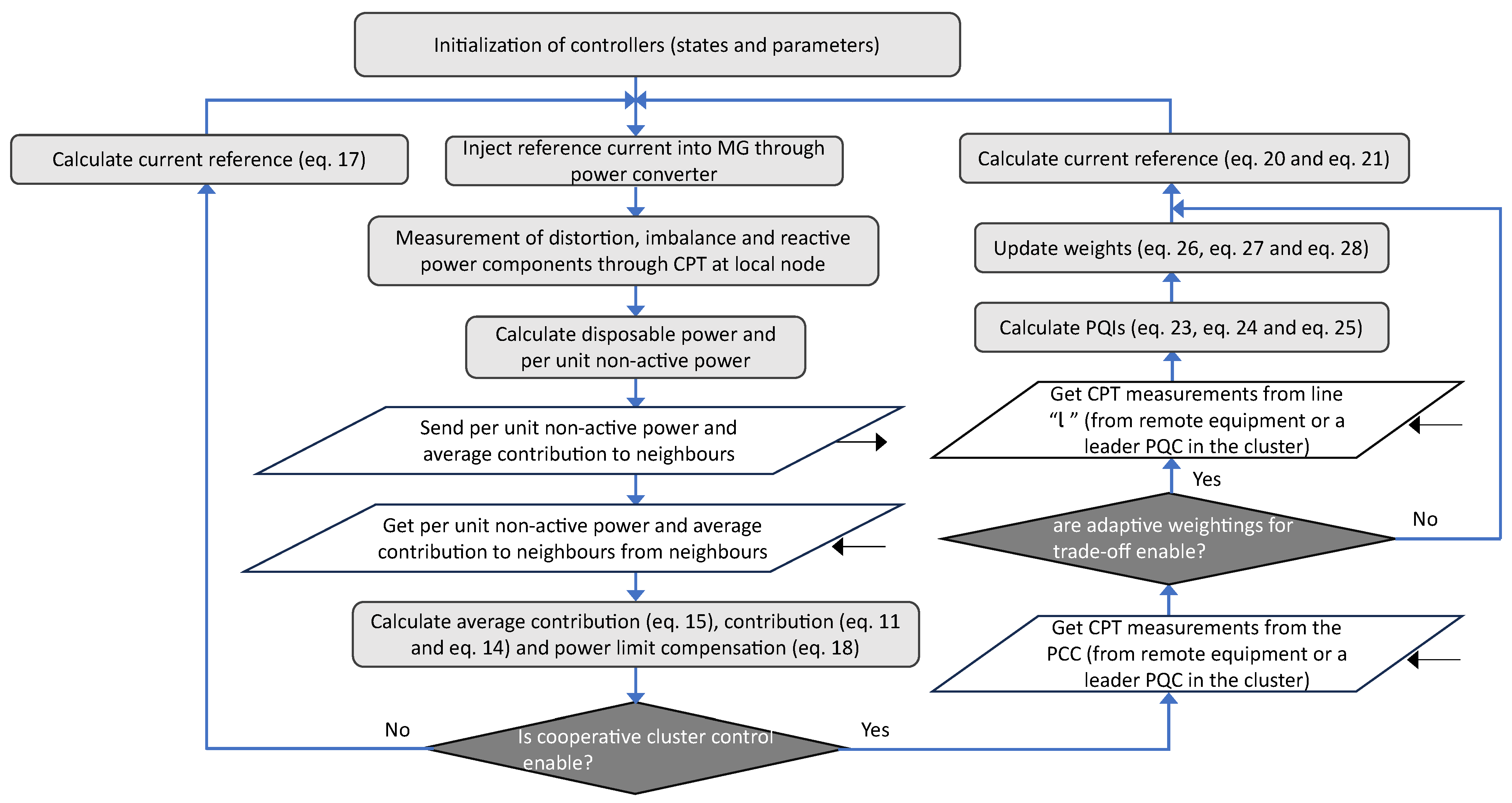
To exemplify the operation of a PQC, a summary flowchart is provided in Figure 3.

5. Case Study

The evaluation of the performance of the control scheme proposed for the clusters of PQCs is realized through experiments in a simulated environment. The simulations are realized in software PLECS [38], version 4.5.9, with a discrete solver with a sample step of 200 (µs). The simulated model is described next.

5.1. Microgrid Model

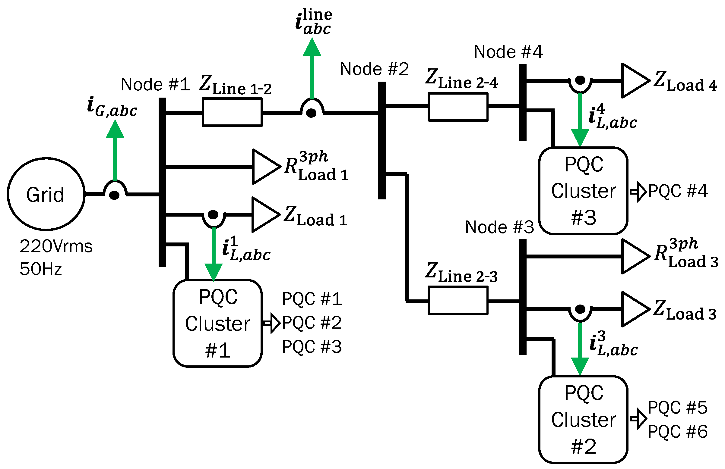
The simulated MG is depicted in Figure 4. It contains four nodes, two balanced loads, three unbalanced loads, and three clusters of PQCs. The unbalanced loads are resistive–inductive and star-connected with a neutral wire. In particular, Unbalanced load #1 has a diode in the c-phase to produce distortion in the current waveforms (mainly a DC component plus a double frequency harmonic). Each PQC is modelled as an ideal current source. The grid is represented as an ideal three-phase voltage source with a fundamental frequency of 50 (Hz) and a voltage amplitude of 220 (Vrms/ph). There are three PQCs composing Cluster #1, two PQCs composing Cluster #2 and only one PQC in Cluster #3.
The parameters of the electrical system are summarized in Table 2 while the control parameters are summarized in Table 3.
The communication layer of PQCs is constructed considering the bidirectional flow of information. The adjacency matrices for Clusters #1, #2, and #3 are
A 1 = 0 1 1 1 0 1 1 1 0 , A 2 = 0 1 1 0 , A 3 = 0 .

5.2. Performance Tests

To evaluate the performance of the controllers during simulations, different scenarios are used; they are described as follows.

5.2.1. Case 1. Multi-Mode Operation

The MG is initially operated without power quality compensation; then, at time t = 3 (s), the local PQC control is activated but without power boundary saturations. Power saturations are activated at t = 6 (s). After that, at t = 9 (s), the cooperative control between clusters of PQCs is activated. Finally, at t = 12 (s), the restriction based on PQIs ( λ Q , l , λ U , l and λ D , l ) is put in action.

5.2.2. Case 2. Communication Issues within a Cluster of PQCs

This case is divided into two tests. In contrast to Case 1 and Case 3, these tests do not contemplate the activation of (18) nor (21). In the first test, the performance of the control strategy is analyzed when a PQC loses its communication before and after the activation of the maximum power constraints (at t = 5 (s) and t = 8 (s), respectively); during the communication failure, parameter N is not updated in order to represent the worst case scenario. The second test is about transport time delays; time delays are introduced in the communication links between the neighbour PQCs within a cluster. Delay ( τ ) values of 0, 100, and 200 (ms) are tested. These values are selected because of their gradual proximity to the convergence rate in the design of (11), which is close to 500 (ms) for Cluster #1 and 1500 (ms) for Cluster #2 when using Table 3.

5.2.3. Case 3. Communication Issues in PQI Compensation

This test uses as a basis the conditions of Case 1. From it, a constant transport delay is added to the communication links between clusters and the PQI measurement on Line 1–2. Delay values of 0, 100 and 200 (ms) are tested.

6. Results and Discussions

6.1. Case 1

The results of Case 1 are shown in Figure 5 and Figure 6. Different variables are grouped and shown to better understand the system’s behavior at various stages of the test. Figure 5 focuses on showing the control variables, whilst Figure 6 shows the effects in the system’s currents and PQIs.
In Figure 5a, we can see the behavior of the consensus variable NA i . Before t = 3 (s), the non-active powers are close to zero since the PQCs are disabled, i.e., the power converters only provide active power to the MG. In the same time span, Figure 5b–d show the behavior of h i , h i and δ h i , where all the variables also keep zero values. During t (3,6), the local power quality compensation is activated in each PQC. As a result, Figure 5a shows that each cluster of PQCs achieves non-active power consensus after a small transient of around 1 (s). However, the values of NA i in Cluster #1 exceed their maximum disposable capacity S i disp (there is overloading). This condition might damage the converters unless hardware protection is provided (which would shut down the converters of Cluster #1). Figure 5b shows that the dynamic of h coefficients follows the same bandwidth of non-active powers. Also, different steady-state values are reached. It can be seen from Figure 5c that the sum of h coefficients inside a cluster is equal to one at almost all times.
This inconvenient operation that exceeds the maximum capacity of converters is fixed after t = 6 (s), where saturation is imposed by (17) and (18). Figure 5a depicts that the non-active powers of Cluster #1 stabilize at their maximum disposable capacity, whereas other clusters remain unchanged. This means there is a reduction in the overall power quality compensation of the system during t (6,9). Figure 5b shows small changes in PQCs contributions, whereas Figure 5d illustrates an increase in deviations in Cluster #1 caused by the power limit constraint. It is worth noting that the effects caused by δ h are not reflected in the charting of Figure 5c, following the same information routing described in Figure 2; the latter ensures the decoupling between (13) and (18).
After t = 9 (s), the cooperative grid-side compensation is activated, where Cluster #2 and Cluster #3 receive measurements from the PCC. The non-active powers of Cluster #2 and Cluster #3 depicted in Figure 5a increase accordingly, and the consensus inside all the clusters holds during the transient (around 2 (s) for Cluster #2 and 0.5 (s) for Cluster #3). Figure 5b shows a negligible variation in the PQC contribution whereas Figure 5d shows a pronounced increment in the compensation for power saturation of PQC #4 (yellow line). This increment of δ h 4 is concordant with the saturation of Cluster #3 seen in Figure 5a.
In the final stage of the test, the adaptive weightings are activated at t = 12 (s). As expected, in Figure 5a, a reduction can be seen in the amount of non-active power that Cluster #2 and Cluster #3 provide to compensate for the power quality at the PCC. Figure 5b,c remain unchanged, which means that the dynamics of the adjustable parameters based on PQIs are decoupled from the control loops of Constraints (12) and (16). Also, the power limit correction of Cluster #3 is reduced to zero, as shown in Figure 5d. This is expected since the non-active power contribution of Cluster #3 is reduced by adjustable parameters.
The behavior of the currents is shown in Figure 6a,c. It can be seen that after the activation of the PQCs, at t = 3 (s), the grid side current is almost immediately free from imbalance and distortion. Also, the currents in distribution line Line 1–2 shown in Figure 6c exhibit an appropriate dynamic (no distortions are introduced into the distribution lines).
Figure 6b,d depict the variations in power quality during the simulation test transitions; these figures show that PQIs improve after the activation of PQCs (t ( 3 , 6 ) ). However, after t = 6 (s), the control loop of (18) drives Cluster #1 to saturation, provoking a lack of compensation at the PCC (Node #1); imbalance and distortion can be seen in Figure 6a during this time span. Also, Figure 6c shows an expected unchanged behavior of Line 1–2, where there are no additional current injections/consumptions. Overall, during t ( 3 , 9 ) , an appropriate behavior of the proposed controller is depicted in Figure 6, achieving all its control goals while abiding by the power constraints.
After t = 9 (s), Clusters #2 and #3 start compensating the PCC, incidentally distorting the distribution lines, as shown in current waveforms of Figure 6a,c and their corresponding PQIs in Figure 6b,d. It can be seen that the combined PQC clusters almost compensate the same amount that the initial local cluster (PQC Cluster #1) did during t ( 3 , 6 ) . It is worth noting that after t = 9 (s), the grid side noticeably reduces its current imbalance and distortion, whereas other distribution lines (like Line 1–2) slightly decrease their power quality; the proportion of power quality compensation of PQC clusters greatly depends on the adjustment of the CPT weights of (27), and (28) and the PQC cluster location. After the application of the PQI restrictions, at t = 12 (s), it can be seen in Figure 6d that the distortion factor in Line 1–2 drops to the maximum allowable value λ D , l max = 0.2 after a nearly 3 (s) transient, which inevitably deteriorates the power quality in the grid side. Therefore, the selection of Line l, as well as its associated PQI values ( λ Q , l , λ U , l , λ D , l ), is sensitive concerning the grid side power quality.

6.2. Case 2

6.2.1. Communication Link Failure inside PQC Cluster

In this case, Figure 7 shows the performance of (11) under the disconnection of PQC #3 of Cluster #1. A seamless operation during the communication failure of PQC #3 ( t ( 5 , 6 ) ) can be seen (a negligible error at this point). After a disturbance (t = 6 (s)), as the power redistributes according to maximum power limits, the PQCs stabilize their values in a close proximity. In particular, before the reconnection, there is an error of 1.88 %; this error vanishes rapidly (around 0.6 (s)) after the reconnection at t = 8 (s), as can be seen from the highlighted zoom. From the simulation data, it can be inferred that the outdated value of N does not have a significant impact on power quality. Also, there is no disturbance in the consensus final value as long as a spanning tree is guaranteed in the communication graph of the cluster.

6.2.2. Communication Delay inside PQC Cluster

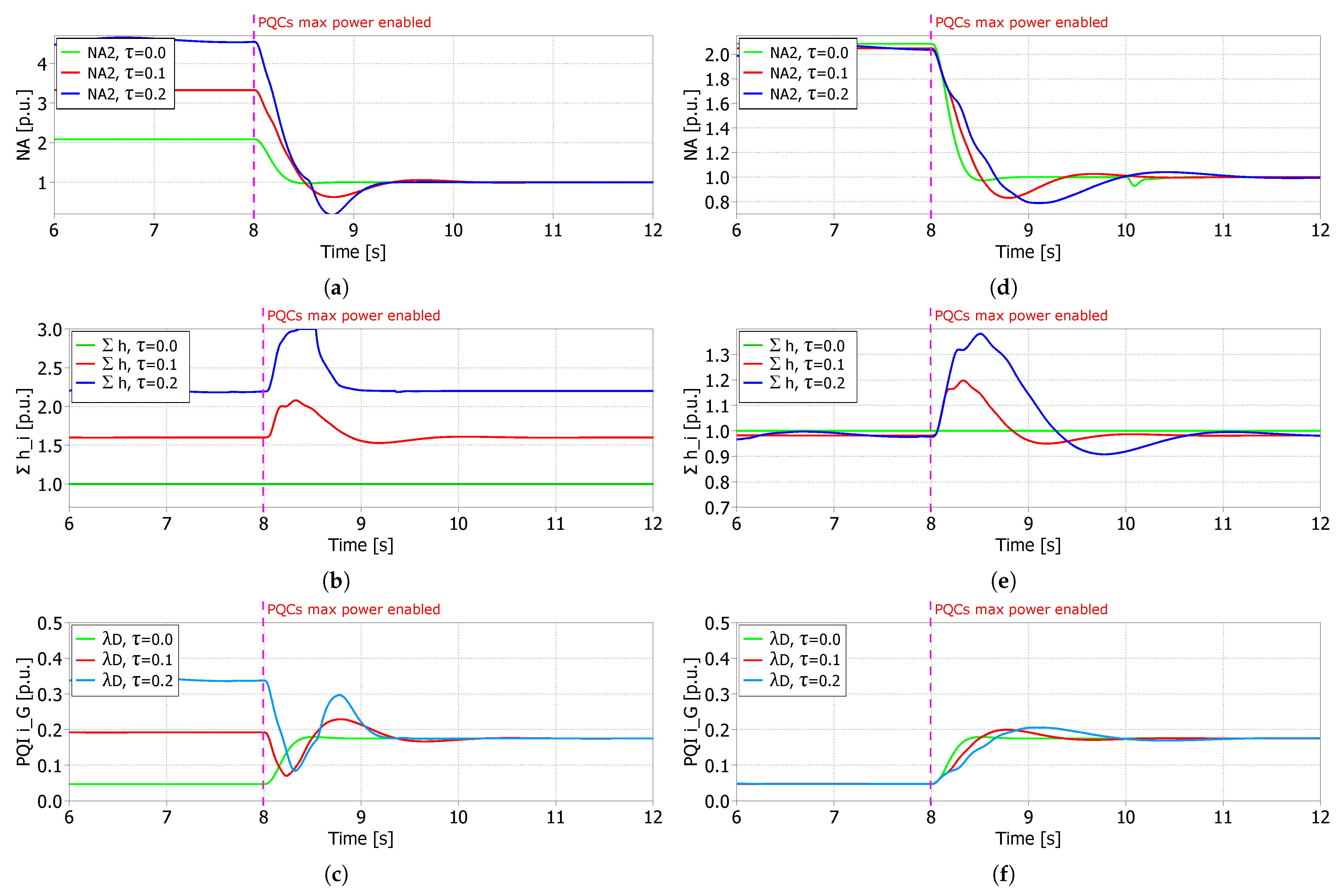
The results with the effect of time delays under Case 2 are presented in Figure 8. The activation time of (18) is changed to t = 8 (s) for this test. Also, for a clear contrast between tests, only the dynamic of PQC #2 is shown. Similarly, only λ D is shown since it is the index with the greatest variation.
Before t = 8 (s), it can be seen in Figure 8a–c that the delay produces steady-state errors proportional to it. This is mainly due to the observer of (15), which has the initial conditions h ¯ j = 0 (needed for convergence [32]) that induce the integration of h i indefinitely before receiving the measurement from neighbouring units. This problem is detailed and reported in [39]. Fortunately, there are solutions reported in the literature, such as using a selective anti-windup [40], reducing c z while slowing down the dynamics of the observer, or using a robust feedback consensus loop [32].
After t = 8 (s), the saturation loop in (18) is activated, which limits the contribution of NA i from each PQC. In this particular case, since NA req is greater than the combined power of Cluster #1, the error of (15) does not affect the MG, since the cluster is not able to “overcompensate”. Additionally, is it important to highlight that, internally, δ h i compensations are applied after the calculation of h i , so each PQC is able to reach non-active power consensus and equilibrium in (16) despite (12) not being met by miscalculated h ¯ i .
In Figure 8d–f, the results are presented but implementing the anti-windup with reset scheme proposed in [40]. It is distinguished that the steady-state error compared with τ = 0 of the charts in Figure 8e is reduced below 2%, which guarantees that the proposed strategy produces accurate measurements of the individual contribution of PQCs. In Figure 8d,f, appropriate power quality compensation is shown; particularly for τ = 0.2 , the anti-windup produces a reduction of 58% in transient overshoot but a slight increase in settling time. Overall, steady-state values in Figure 8d,f remain the sameas those in Figure 8a,c after t = 8 (s). Therefore, the application of a time delay robust method is optional and only necessary when contributions h i are required to be measured for a decision-making process.

6.3. Case 3

The results are shown in Figure 9 and Figure 10. In Figure 9, non-active powers of PQCs are shown when subdued to a delay of 0.2 (s) in the data received for executing (26)–(28). It can be seen after the activation of the adjustable PQIs at t = 12 (s) that the non-active power contributions of Cluster #2 and Cluster #3 suffer minor changes in their waveforms (transient states) when compared with the results presented in Figure 5a for Case 1. Particularly, the system damping is decreased and the convergence is slightly slower (≈0.15 (s) slower for an error band of 2%).
The change in PQIs regarding time delays in the dynamics of (21) is shown in detail in Figure 10. Here, the simulation time is extended by 1.5 (s) and the PQI control is enabled at t = 14 (s), i.e., two seconds later, for a better visualization of the delay phenomenon. As the harmonic distortion is the only variable exceeding the defined PQI limits for Line 1–2, it should be enough to analyze only this waveform. However, for completeness, the other PQIs are displayed. From Figure 10a, it can be seen that the delay in the communication of the PQIs causes a minimal deterioration in the transient state. Figure 10b,c present the unchanged status from the reactivity and unbalance factors, as expected since they are inside the defined threshold. Because the updating of Loops (26)–(28) is slow (i.e., small values of k k r , l c l , k k u , l c l and k k v , l c l ), control coupling (and hence oscillations) are avoided; then, the system can operate satisfactorily in the face of relatively large transport delays.

7. Conclusions

The proposed methodology deals with the coordination of multiple converters in an MG to act as PQCs that improve the power quality at selected buses and the PCC. On a side, the proposed distributed controller ensures a flexible approach to synchronising the actions of several PQCs without prior knowledge of initial conditions. On the other side, the proposed CPT weights deal with the trade-offs of local and grid-side compensation by means of PQIs.
Results show that the distributed control scheme proposed in this work is able to satisfactorily coordinate PQCs in a cluster whilst permitting other clusters of PQCs to support the power quality compensation at the PCC, where convergences in the range of 0.5–1.0 (s) within clusters and 1.0–3.0 (s) for multi-cluster cooperations are seen according to the designed control bandwidths. It can also be seen from simulations that the control effort is distributed and that the proposed consensus dynamics do not adversely affect the transient state operation when communication issues exist. For communication losses inside a cluster, there is a steady-state error <2% if no actions are taken regarding the control parameters. For time delays inside a cluster, settling times are increased over 1.5 times for a delay of 200 (ms), whereas steady-state values remain unchanged. In the case of delays between line measurements and a cluster of PQCs, the settling times increase by 7% with the steady-state value unaffected when 200 (ms) of time delays are considered. Therefore, the proposed strategy is reliable for common communication issue scenarios.
The results allow concurrent analysis and design of the distributed compensation system and a cooperative operation of multiple compensators acting in the same MG. Future work will be carried out for the proposed method related to the resiliency of communications. In this regard, it will be relevant to study cyber attacks over the PQCs since they might likely deteriorate the power quality of the MG. Also, the extension to isolated and hybrid MG topologies will bring new insights into the full potential of the proposed methods.

Author Contributions

Conceptualization, C.B.-M., H.K.M.-P. and M.M.-G.; methodology, M.M.-G. and C.B.-M.; software, C.B.-M. and M.M.-G.; validation, M.M.-G. and A.K.V.; formal analysis, M.M.-G.; investigation, C.B.-M. and M.M.-G.; resources, C.B.-M., M.M.-G. and J.S.G.; data curation, M.M.-G. and A.K.V.; writing—original draft preparation, C.B.-M., H.K.M.-P. and J.S.G.; writing—review and editing, C.B.-M., H.K.M.-P., M.M.-G., J.S.G., A.K.V. and J.P.B.; visualization, M.M.-G. and J.S.G.; supervision, C.B.-M., H.K.M.-P. and J.P.B.; project administration, C.B.-M. and J.S.G.; funding acquisition, J.S.G., C.B.-M., H.K.M.-P. and M.M.-G. All authors have read and agreed to the published version of the manuscript.

Funding

This research was funded in part by the National Agency for Research and Development (ANID) under grant ANID PIA ACT192013, in part by the National Council for Scientific and Technological Development (CNPq) under grant 309297/2021-4; and in part by the Sao Paulo Research Foundation (FAPESP) under grant 2022/15423-3. J.S. Gómez acknowledges the support of UNAB Regular funds (project DI-02-23/REG). M. Martínez-Gómez acknowledges the support of ANID under the grant ANID-Becas/Doctorado Nacional 2019-21191757. J.P. Bonaldo acknowledges the support of Mato Grosso Research Foundation under grant FAPEMAT.0001047/2022.

Institutional Review Board Statement

Not applicable.

Informed Consent Statement

Not applicable.

Data Availability Statement

No new data were created or analyzed in this study. Data sharing is not applicable to this article.

Conflicts of Interest

The authors declare no conflict of interest. The funders had no role in the design of the study; in the collection, analyses, or interpretation of data; in the writing of the manuscript; or in the decision to publish the results.

Abbreviations

The following abbreviations are used in this manuscript:
MGMicrogrid
NCRENon-conventional renewable energy
LVLow voltage
DFACTSDistributed flexible AC transmission systems
SAPFShunt active power filter
STATCOMStatic synchronous compensator
PQCPower quality compensator
PCCPoint of common coupling
CPTConservative power theory
VAVolt-ampere
DSCDelayed Signal Cancellation
MPPTMaximum power point tracking
PQIPower quality index

References

  1. Schwaegerl, C.; Tao, L. The Microgrids Concept. In Microgrids; John Wiley & Sons, Ltd.: Hoboken, NJ, USA, 2013; Chapter 1; pp. 1–24. [Google Scholar] [CrossRef]
  2. Espina, E.; Llanos, J.; Burgos-Mellado, C.; Cárdenas, R.; Martínez-Gómez, M.; Sáez, D. Distributed control strategies for microgrids: An overview. IEEE Access 2020, 8, 193412–193448. [Google Scholar] [CrossRef]
  3. Olivares, D.E.; Mehrizi-Sani, A.; Etemadi, A.H.; Cañizares, C.A.; Iravani, R.; Kazerani, M.; Hajimiragha, A.H.; Gomis-Bellmunt, O.; Saeedifard, M.; Palma-Behnke, R.; et al. Trends in microgrid control. IEEE Trans. Smart Grid 2014, 5, 1905–1919. [Google Scholar] [CrossRef]
  4. Hernández-Mayoral, E.; Madrigal-Martínez, M.; Mina-Antonio, J.D.; Iracheta-Cortez, R.; Enríquez-Santiago, J.A.; Rodríguez-Rivera, O.; Martínez-Reyes, G.; Mendoza-Santos, E. A Comprehensive Review on Power-Quality Issues, Optimization Techniques, and Control Strategies of Microgrid Based on Renewable Energy Sources. Sustainability 2023, 15, 9847. [Google Scholar] [CrossRef]
  5. Afonso, J.L.; Tanta, M.; Pinto, J.G.O.; Monteiro, L.F.C.; Machado, L.; Sousa, T.J.C.; Monteiro, V. A Review on Power Electronics Technologies for Power Quality Improvement. Energies 2021, 14, 8585. [Google Scholar] [CrossRef]
  6. Vineeth, G.; Aishwarya, J.; Sowmya, B.; Rani, B.; Narasimha, M. Power Quality Enhancement in Grid-Connected Renewable Energy Sources Using MC-UPQC. In Proceedings of the 2023 International Conference on Power, Instrumentation, Energy and Control (PIECON), Aligarh, India, 10–12 February 2023; pp. 1–6. [Google Scholar] [CrossRef]
  7. Wang, N.; Zheng, S.; Gao, W. Microgrid Harmonic Mitigation Strategy Based on the Optimal Allocation of Active Power and Harmonic Mitigation Capacities of Multi-Functional Grid-Connected Inverters. Energies 2022, 15, 6109. [Google Scholar] [CrossRef]
  8. Chawda, G.S.; Shaik, A.G.; Mahela, O.P.; Padmanaban, S.; Holm-Nielsen, J.B. Comprehensive Review of Distributed FACTS Control Algorithms for Power Quality Enhancement in Utility Grid With Renewable Energy Penetration. IEEE Access 2020, 8, 107614–107634. [Google Scholar] [CrossRef]
  9. Guerrero, J.M.; Loh, P.C.; Lee, T.L.; Chandorkar, M. Advanced Control Architectures for Intelligent Microgrids—Part II: Power Quality, Energy Storage, and AC/DC Microgrids. IEEE Trans. Ind. Electron. 2013, 60, 1263–1270. [Google Scholar] [CrossRef]
  10. Pattery, J.M.; Jayaprakasan, S.; Cheriyan, E.P.; Ramchand, R. A Composite Strategy for Improved Power Quality Using Micro Compensators in Secondary Distribution Systems. IEEE Trans. Power Deliv. 2022, 37, 1027–1035. [Google Scholar] [CrossRef]
  11. Yang, J.; Qi, R.; Liu, Y.; Ding, Y. Coordinated Control Strategy for Harmonic Compensation of Multiple Active Power Filters. Energy Eng. 2022, 119, 609–620. [Google Scholar] [CrossRef]
  12. Soto, D.; Green, T. A comparison of high-power converter topologies for the implementation of FACTS controllers. IEEE Trans. Ind. Electron. 2002, 49, 1072–1080. [Google Scholar] [CrossRef]
  13. Perez, M.A.; Ceballos, S.; Konstantinou, G.; Pou, J.; Aguilera, R.P. Modular Multilevel Converters: Recent Achievements and Challenges. IEEE Open J. Ind. Electron. Soc. 2021, 2, 224–239. [Google Scholar] [CrossRef]
  14. Kontos, E.; Tsolaridis, G.; Teodorescu, R.; Bauer, P. High Order Voltage and Current Harmonic Mitigation Using the Modular Multilevel Converter STATCOM. IEEE Access 2017, 5, 16684–16692. [Google Scholar] [CrossRef]
  15. Morales Paredes, H.K.; Costabeber, A.; Tenti, P. Application of Conservative Power Theory to cooperative control of distributed compensators in smart grids. In Proceedings of the 2010 International School on Nonsinusoidal Currents and Compensation, Lagow, Poland, 15–18 June 2010; pp. 190–196. [Google Scholar] [CrossRef]
  16. Marini, A.; Ghazizadeh, M.S.; Mortazavi, S.S.; Piegari, L. A harmonic power market framework for compensation management of DER based active power filters in microgrids. Int. J. Electr. Power Energy Syst. 2019, 113, 916–931. [Google Scholar] [CrossRef]
  17. Mortezaei, A.; Simoes, M.G.; Savaghebi, M.; Guerrero, J.M.; Al-Durra, A. Cooperative Control of Multi-Master–Slave Islanded Microgrid With Power Quality Enhancement Based on Conservative Power Theory. IEEE Trans. Smart Grid 2018, 9, 2964–2975. [Google Scholar] [CrossRef]
  18. Munir, H.M.; Ghannam, R.; Li, H.; Younas, T.; Golilarz, N.A.; Hassan, M.; Siddique, A. Control of Distributed Generators and Direct Harmonic Voltage Controlled Active Power Filters for Accurate Current Sharing and Power Quality Improvement in Islanded Microgrids. Inventions 2019, 4, 27. [Google Scholar] [CrossRef]
  19. Simpson-Porco, J.W.; Shafiee, Q.; Dorfler, F.; Vasquez, J.C.; Guerrero, J.M.; Bullo, F. Secondary Frequency and Voltage Control of Islanded Microgrids via Distributed Averaging. IEEE Trans. Ind. Electron. 2015, 62, 7025–7038. [Google Scholar] [CrossRef]
  20. Ding, G.; Wei, R.; Zhou, K.; Gao, F. Communication-less harmonic compensation in a multi-bus microgrid through autonomous control of distributed generation grid-interfacing converters. J. Mod. Power Syst. Clean Energy 2015, 3, 597–609. [Google Scholar] [CrossRef]
  21. Skjong, E.; Suul, J.; Molinas, M.; Johansen, T. Optimal Compensation of Harmonic Propagation in a Multi-Bus Microgrid. Renew. Energy Power Qual. J. 2016, 236–241. [Google Scholar] [CrossRef]
  22. Gomez, J.S.; Llanos, J.; Espina, E.; Burgos-Mellado, C.; Rodriguez, J. Cooperative Power Conditioners for Microgrids in Mining. In Proceedings of the 2021 23rd European Conference on Power Electronics and Applications (EPE’21 ECCE Europe), Ghent, Belgium, 6–10 September 2021; pp. 1–10. [Google Scholar] [CrossRef]
  23. Yang, Z.; Yi, H.; You, Y.; Zhuo, F.; Zhan, C.; Shi, S. Optimal Installation and System-level Control Strategy of SAPF Based on Extended-range Compensation of Multi-bus Harmonic Sources in Distribution Networks. In Proceedings of the 2023 25th European Conference on Power Electronics and Applications (EPE’23 ECCE Europe), Aalborg, Denmark, 4–8 September 2023; pp. 1–9. [Google Scholar] [CrossRef]
  24. Wada, K.; Fujita, H.; Akagi, H. Considerations of a shunt active filter based on voltage detection for installation on a long distribution feeder. IEEE Trans. Ind. Appl. 2002, 38, 1123–1130. [Google Scholar] [CrossRef]
  25. Tenti, P.; Paredes, H.K.M.; Mattavelli, P. Conservative Power Theory, a Framework to Approach Control and Accountability Issues in Smart Microgrids. IEEE Trans. Power Electron. 2011, 26, 664–673. [Google Scholar] [CrossRef]
  26. Paredes, H.K.M.; Rodrigues, D.T.; Cebrian, J.C.; Bonaldo, J.P. CPT-Based Multi-Objective Strategy for Power Quality Enhancement in Three-Phase Three-Wire Systems Under Distorted and Unbalanced Voltage Conditions. IEEE Access 2021, 9, 53078–53095. [Google Scholar] [CrossRef]
  27. Wang, Y.F.; Li, Y.W. Grid Synchronization PLL Based on Cascaded Delayed Signal Cancellation. IEEE Trans. Power Electron. 2011, 26, 1987–1997. [Google Scholar] [CrossRef]
  28. Svensson, J.; Bongiorno, M.; Sannino, A. Practical Implementation of Delayed Signal Cancellation Method for Phase-Sequence Separation. IEEE Trans. Power Deliv. 2007, 22, 18–26. [Google Scholar] [CrossRef]
  29. Neves, F.A.S.; Cavalcanti, M.C.; de Souza, H.E.P.; Bradaschia, F.; Bueno, E.J.; Rizo, M. A Generalized Delayed Signal Cancellation Method for Detecting Fundamental-Frequency Positive-Sequence Three-Phase Signals. IEEE Trans. Power Deliv. 2010, 25, 1816–1825. [Google Scholar] [CrossRef]
  30. Morales-Paredes, H.K.; Burgos-Mellado, C.; Bonaldo, J.P.; Rodrigues, D.T.; Quintero, J.S.G. Cooperative control of power quality compensators in microgrids. In Proceedings of the 2021 IEEE Green Technologies Conference (GreenTech), Denver, CO, USA, 7–9 April 2021; pp. 380–386. [Google Scholar] [CrossRef]
  31. Stevanoni, C.; Deblecker, O.; Vallée, F. Cooperative Control Strategy of Multifunctional Inverters For Power Quality Enhancement in Smart Microgrids. Renew. Energy Power Qual. J. 2016, 73–78. [Google Scholar] [CrossRef]
  32. Spanos, D.; Olfati-Saber, R.; Murray, R. Dynamic consensus on mobile networks. In Proceedings of the 16th IFAC World Congress, Prague, Czech Republic, 3–8 July 2005; pp. 1–6. [Google Scholar]
  33. Hedetniemi, S.M.; Hedetniemi, S.T.; Liestman, A.L. A survey of gossiping and broadcasting in communication networks. Networks 1988, 18, 319–349. [Google Scholar] [CrossRef]
  34. Llanos, J.; Olivares, D.; Simpson-Porco, J.; Mehrdad, K.; Sáez, D. A Novel Distributed Control Strategy for Optimal Dispatch of Isolated Microgrids Considering Congestion. IEEE Trans. Smart Grid 2019, 10, 6595–6606. [Google Scholar] [CrossRef]
  35. Zhang, H.; Lewis, F.L.; Das, A. Optimal Design for Synchronization of Cooperative Systems: State Feedback, Observer and Output Feedback. IEEE Trans. Autom. Control. 2011, 56, 1948–1952. [Google Scholar] [CrossRef]
  36. Costabeber, A.; Tenti, P.; Caldognetto, T.; Liberado, E.V. Selective compensation of reactive, unbalance, and distortion power in smart grids by synergistic control of distributed switching power interfaces. In Proceedings of the 2013 15th European Conference on Power Electronics and Applications (EPE), Lille, France, 2–6 September 2013; pp. 1–9. [Google Scholar] [CrossRef]
  37. Moreira, A.C.; Paredes, H.K.M.; de Souza, W.A.; Marafão, F.P.; da Silva, L.C.P. Intelligent Expert System for Power Quality Improvement Under Distorted and Unbalanced Conditions in Three-Phase AC Microgrids. IEEE Trans. Smart Grid 2018, 9, 6951–6960. [Google Scholar] [CrossRef]
  38. Plexim. PLECS The Simulation Platform for Power Electronic Systems. Available online: https://www.plexim.com/products/plecs (accessed on 24 October 2023).
  39. Moradian, H.; Kia, S.S. On Robustness Analysis of a Dynamic Average Consensus Algorithm to Communication Delay. IEEE Trans. Control. Netw. Syst. 2019, 6, 633–641. [Google Scholar] [CrossRef]
  40. Martinez-Gomez, M.; Orchard, M.E.; Bozhko, S. Dynamic Average Consensus with Anti-windup applied to Interlinking Converters in AC/DC Microgrids under Economic Dispatch and Delays. IEEE Trans. Smart Grid 2023, 14, 4137–4140. [Google Scholar] [CrossRef]
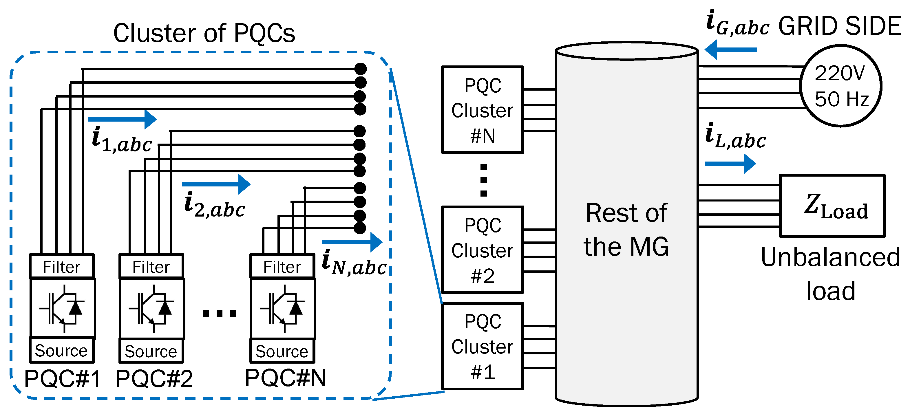
Figure 1. Illustration of a cluster of PQCs used in this work.
Sustainability 15 15698 g001
Figure 2. Schematic representation of the proposed control loops for PQCs.
Sustainability 15 15698 g002
Figure 3. Summary flowchart of the main operation of PQCs.
Sustainability 15 15698 g003
Figure 4. Unilinear diagram of the studied MG system used for simulations.
Sustainability 15 15698 g004
Figure 5. Measured variables during simulation of Case 1. (a) Non-active powers of PQCs. (b) Contribution of PQCs ( h i ). (c) Cumulative contribution of PQC clusters (fulfilment of (12)). (d) Power limit compensation (fulfilment of (16)).
Sustainability 15 15698 g005
Figure 6. Measured variables during simulation of Case 1. (a) Currents in grid side. (b) PQIs in grid side. (c) Currents in Line 1–2. (d) PQIs in Line 1–2.
Sustainability 15 15698 g006
Figure 7. Non-active powers of Cluster #1 during simulation of communication failure in Case 2.
Sustainability 15 15698 g007
Figure 8. Effect of delays in Cluster #1 during simulation of Case 2. (a) Non-active power of PQCs. (b) Cumulative contribution of PQC cluster (fulfilment of (12)). (c) Harmonic distortion factor at grid side. (d) Non-active power using anti-windup. (e) Cumulative contribution of the PQC cluster (fulfilment of (12)) using anti-windup. (f) Harmonic distortion factor at grid side using anti-windup.
Sustainability 15 15698 g008
Figure 9. Non-active powers of PQCs during simulation of Case 3.
Sustainability 15 15698 g009
Figure 10. Effect of delays in Line 1–2 during simulation of Case 3. (a) Harmonic distortion factor. (b) Reactivity factor. (c) Unbalance factor.
Sustainability 15 15698 g010
Table 1. Comparison of the proposed method with the published works in the literature.
ReferencesAdditional
Hardware
Communication
(If Available)
Multi-Bus
Compensation
Need Synchronizer
or DSC
Implementation
Costs
[6,14]centralized×$  $  $
[10,11,21,23,24]centralized$  $  $
[16,17,18]×centralized×$  $
[7]×centralized$  $
[15,26]×centralized××$  $
[31]×centralized×$  $
[20,22]×distributed$
[30]×distributed××$
Proposal×distributed×$
Table 2. Electrical parameters for simulation.
VariableValueVariableValueVariableValue
R line 1 2 0.3 ( Ω ) L line 1 2 1.0 (mH) R Load 1 3 p h 150 ( Ω )
R line 2 3 0.1 ( Ω ) L line 2 3 0.3 (mH) R Load 3 3 p h 100 ( Ω )
R line 2 4 0.3 ( Ω ) L line 2 4 1.0 (mH)
R Load 1 a 10 ( Ω ) R Load 1 b 15 ( Ω ) R Load 1 c 7 ( Ω )
L Load 1 a 10 (mH) L Load 1 b 15 (mH) L Load 1 c 15 (mH)
R Load 3 a 40 ( Ω ) R Load 3 b 56 ( Ω ) R Load 3 c 36 ( Ω )
L Load 3 a 15 (mH) L Load 3 b 15 (mH) L Load 3 c 15 (mH)
R Load 4 a 100 ( Ω ) R Load 4 b 150 ( Ω ) R Load 4 c 100 ( Ω )
L Load 4 a 1 (mH) L Load 4 b 1 (mH) L Load 4 c 1 (mH)
Table 3. Control parameters for simulation.
VariableValueVariableValueVariableValue
S 1 max 1.5 (kVA) S 2 max 1.5 (kVA) S 3 max 1.0 (kVA)
S 4 max 1.7 (kVA) S 5 max 1.5 (kVA) S 6 max 2.0 (kVA)
P 1 ref 0.3 (kW) P 2 ref 0.2 (kW) P 3 ref 0.2 (kW)
P 4 ref 0.5 (kW) P 5 ref 0.5 (kW) P 6 ref 0.5 (kW)
λ Q , l max 0.50 λ U , l max 0.20 λ D , l max 0.20
c n 1 4.00 c n 2 10.00 c n 3 1.00
c z 3.00 k p z 0.00 k i z 14.64
k h 1 0.18 k h 2 0.75 k h 3 2.00
k k r , l 1 2.00 k k u , l 1 2.00 k k v , l 1 0.60
k p , r u 2.00 k p , u u 2.00 k p , v u 0.60
k i , r u 24.66 k i , u u 24.66 k i , v u 2.46
ω F 8.97 ( rad s ) k 1 0.20 k 2 100
Disclaimer/Publisher’s Note: The statements, opinions and data contained in all publications are solely those of the individual author(s) and contributor(s) and not of MDPI and/or the editor(s). MDPI and/or the editor(s) disclaim responsibility for any injury to people or property resulting from any ideas, methods, instructions or products referred to in the content.