Article

Interface Optimization of Cu2S Nanoparticles by Loading N-Doped Carbon for Efficient Sodium-Ion Storage

1
Tianjin Key Laboratory of Brine Chemical Engineering and Resource Eco-Utilization, College of Chemical Engineering and Materials Science, Tianjin University of Science and Technology, 13th Avenue 29, TEDA, Tianjin 300457, China
2
Key Laboratory for Special Functional Materials of Ministry of Education, National & Local Joint Engineering Research Center for High-Efficiency Display and Lighting Technology, School of Materials Science and Engineering, and Collaborative Innovation Center of Nano Functional Materials and Applications, Henan University, Minglun Street 85, Kaifeng 475004, China
*
Authors to whom correspondence should be addressed.
These authors contributed equally to this work.
Sustainability 2023, 15(24), 16846; https://doi.org/10.3390/su152416846
Submission received: 15 November 2023 / Revised: 8 December 2023 / Accepted: 13 December 2023 / Published: 14 December 2023
(This article belongs to the Section Sustainable Materials)

Abstract

:
Rapid capacity fading and sluggish diffusion kinetics resulting from crystal conversion/powder pulverization hinder practical energy storage application of conversion-type electrodes. To address this issue, we prepared a Cu2S/polyelectrolyte/graphene composite (denoted as Cu2S/PG) through interfacial optimization by incorporating a polyelectrolyte to enhance the connection between Cu2S powders and N-doped graphene. In comparison to CuS and Cu2S, the electrochemical performance of Cu2S/PG was significantly improved by nanocrystallization and carbon-coating, which delivers a capacity of 317 mAh g–1 at 0.1 A g–1 after 200 cycles. Moreover, we performed real-time analysis of the phase conversion and resistance evolution of the Cu2S/PG electrode during Na+ insertion/desertion using in situ X-ray diffraction (XRD) and in operando electrochemical impedance spectroscopy (EIS). Thus, the formation of the intermediate phase (Na2S2) was firstly discovered, which finally converts to Na2S by the end of the sodiation process. In sum, the N-doped carbon/graphene wrapping acts as a protective barrier against electrolyte side reactions, thereby effectively improving the cyclability of the conversion-type Cu2S electrodes.

1. Introduction

In recent decades, the extensive application of lithium-ion batteries in consumer electronics and electric vehicles has been notable, but has finally been constrained due to the limited availability and uneven distribution of lithium [1,2,3,4]. Consequently, there exists a pressing necessity for low-cost energy storage systems in renewable grids and power plants that has propelled escalated research into affordable sodium-ion batteries (SIBs), because they have been considered as potential alternatives due to the significantly high natural availability of sodium (2.75%) [5,6]. However, some issues for commercial usage of SIBs should be addressed, chiefly due to prevailing challenges such as their low energy density and subpar cycle lifespan. Therefore, there is much attention given to high-performance electrode materials for SIBs. Here, three types of SIB anode materials are generally recognized: intercalation type (such as hard carbon and Na2Ti3O7), alloying type (including Sn and Sb), and conversion type (such as CuO and SnS) [7,8]. Moreover, transition metal sulfides (TMSs, like FeS2, SnS2, NiS, MnS, CuS, CoS, and ZnS) have attracted significant attention as conversion-type anodes for SIBs due to their high theoretical capacities and the low cost of materials [9,10,11,12,13,14,15]. Among them, copper sulphides (CuxS, x = 1~2) demonstrate relatively high theoretical capacities, ranging from 564 to 337 mAh g−1 [16]. For instance, the Cu1.8S electrode displays a capacity of approximately 420 mAh g−1 due to the occurrence of both of Cu0/Cu1+ and Cu1+/Cu2+ redox couples [17]. Furthermore, Cu2S exhibits enhanced conductivity attributed to its smaller bandgap (1.21 eV) [18] and larger Cu-S bond length (2.25~2.35 Å) when compared to CuS (~2.191 Å) [7,19]. Consequently, Cu2S has demonstrated better electrochemical performance, characterized by long potential plateaus and high initial Coulombic efficiency [20,21].
Despite possessing the aforementioned advantages, Cu2S faces critical challenges in electrochemical cycling, including electrode pulverization, capacity fading, and polysulfide formation [14]. In order to overcome these issues, two strategies have been widely applied: the first strategy involves the synthesis of TMS nanoparticles, while the second strategy is surface modification through carbon coating. In detail, TMS nanoscaling can mitigate internal stress induced by volume changes during cycling, thus relieving the occurrence of microcracks. Furthermore, surface coating not only preserves particle integrity but also hinders side reaction with liquid electrolyte, thereby promoting the formation of a stable solid electrolyte interphase (SEI) film [10,22]. Additionally, the introduction of a heteroatom-doped carbon layer serves as a physical barrier to inhibit polysulfide shuttling. Finally, it enhances wettability and compatibility between electrodes and electrolytes, resulting in improved electronic conductivity and ionic transferability [7,19,23,24].
As mentioned above, a composite electrode material consisting of Cu2S nanoparticles embedded in N-doped graphene was designed, achieving high capacity and cycling stability as an SIB anode. In this study, a simple precipitation and thermal reduction method was employed to synthesize CuS nanoparticles and a Cu2S/polyelectrolyte/graphene composite (denoted as Cu2S/PG), respectively. The influence of N-doping carbon on the electrochemical performance of the Cu2S/PG composite was systematically assessed. Additionally, in situ XRD was utilized to uncover the phase transition of Cu2S during sodiation/desodiation processes, while in operando EIS was conducted to analyze the evolution of resistance. The results could suggest that Cu2S/PG provides a short ionic pathway for Na+ ions and exhibits remarkable cycling stability, making it a promising candidate for anode materials in SIBs.

2. Materials and Methods

2.1. Materials and Reagents

Firstly, Copper Sulfide (CuS) nanoparticles were fabricated utilizing the precipitation technique inspired by the previous report [25], as illustrated in Figure 1a. Copper nitrate trihydrate (Cu(NO3)2·3H2O) with purity ≥98.0% and thioacetamide (C2H5NS) with purity ≥99.0% were obtained from Sigma-Aldrich (St. Louis, MO, USA). The reactants were used in a S:Cu molar ratio of 1.1:1.0. A 10 wt.% aqueous solution of thioacetamide was incrementally added to a boiling solution containing 0.5M Cu2+. Following 15 min of vigorous agitation, the resulting precipitate was repeatedly washed and centrifuged using both deionized water and ethanol. The precipitate material was then dried at 80 °C in a vacuum oven for 12 h to obtain the black CuS precursor.
The Cu2S/graphene composite was prepared utilizing electrostatic attraction and thermal reduction methods [26]. A total of 0.50 g of CuS precursor and 1.25 g of poly(diallyldimethylammonium chloride) (PDDA) with 20 wt.% concentration from Aldrich were dispersed in 100 mL of deionized water by vigorous stirring, forming suspension A. Simultaneously, 0.10 g of graphene from Inner Mongolia Dasheng Co., Ltd. (Hohhot, China) and 0.84 g of poly(sodium-4-styrenesulfonate) (PSS) with 30 wt.% concentration from Aldrich were dispersed in 20 mL of deionized water to form suspension B. Suspensions A and B were thoroughly mixed by vigorous stirring again. The obtained sediment was washed and dried at 80 °C for 12 h. After carbonization under argon flow at 500 °C for 3 h, the final obtained composite sample was denoted as Cu2S/PG.
For the control group, Cu2S nanoparticles were prepared using a precipitation reaction between Cu(NO3)2, thiosemicarbazide (>99%, Sigma-Aldrich), and Na2SO3 (≥98.0%, Sigma-Aldrich) employed as a mild reducing agent [27]. The solutions with a Cu2+:S2− ratio of 2.0:1.1 (molar ratio) were mixed using ultrasonic irradiation at 100 °C for 10 min. Subsequently, the resulting black precipitate was separated through centrifugation, washed several times with deionized water and ethanol, and finally collected as Cu2S particles after drying at 80 °C in a vacuum oven for 12 h.

2.2. General Characterization

The morphology of the prepared samples was characterized using a Hitachi SU1510 Scanning Electron Microscope (SEM, Tokyo, Japan). Quantitative elemental analysis was identified with Energy-Dispersive X-ray Spectroscopy (EDS) by Bruker. Raman measurements were obtained using a 523 nm laser with a Horiba JY HR-800 Raman spectrometer (Longjumeau, France). Crystallographic data were acquired with a Bruker D8 Venture (Karlsruhe, Germany) using Mo Kα1 radiation (λ = 0.70932 Å), covering a 2θ range of 10° to 50°. Analytical assessment of the acquired diffraction patterns was carried out using the Rietveld refinement method utilizing FullProf software (Version 1.2.4) [28]. X-ray Photoelectron Spectroscopy (XPS) was conducted using a Thermo ESCALAB XI+ XPS spectrometer (Waltham, MA, USA).

2.3. Electrochemical Characterization

In this study, the working electrodes were fabricated using an active material (80 wt.%), carbon black (10 wt.%, super P Li, Timcal, Willebroek, Belgium), and PVDF binder (10 wt.%, R6020/1001, Solvay, Brussels, Belgium). The slurry was then doctor bladed onto a copper foil. Afterward, the coated foil underwent initial drying at room temperature for 2 h, followed by further drying at 80 °C for 12 h. Subsequently, the coated foil was punched into discs with a diameter of ϕ12 mm to serve as working electrodes. Coin cells of CR2032 type were assembled within an argon-filled glovebox (Super, Mikrouna Mech, Beijing, China). Each coin cell consisted of a working electrode, a Whatman® separator (ϕ17 mm), a sodium foil (ϕ15 mm, Alfa Aesar, Ward Hill, MA, USA), and 200 μL of 1 M NaClO4 in EC/PC electrolyte. Galvanostatic cycling with potential limitation (GCPL) and cyclic voltammetry (CV) techniques were employed using a Bio-Logic potentiostat (Seyssinet-Pariset, France), utilizing a potential range of 3.0 to 0.01 V vs. Na/Na+ to investigate the electrochemical performance. To analyze the Na+ storage mechanism of the Cu2S/PG electrode, a coin cell with a Kapton foil window was assembled for an in situ XRD experiment. The cell was cycled at 80 mA g−1 within a potential range of 0.01 to 3.0 V vs. Na/Na+ during the XRD testing. Furthermore, a three-electrode EL-cell® was assembled to conduct in operando EIS tests, with the cell cycled over a potential interval of 0.185 V within a voltage range from the open-circuit voltage to 0.01 V.

3. Results and Discussion

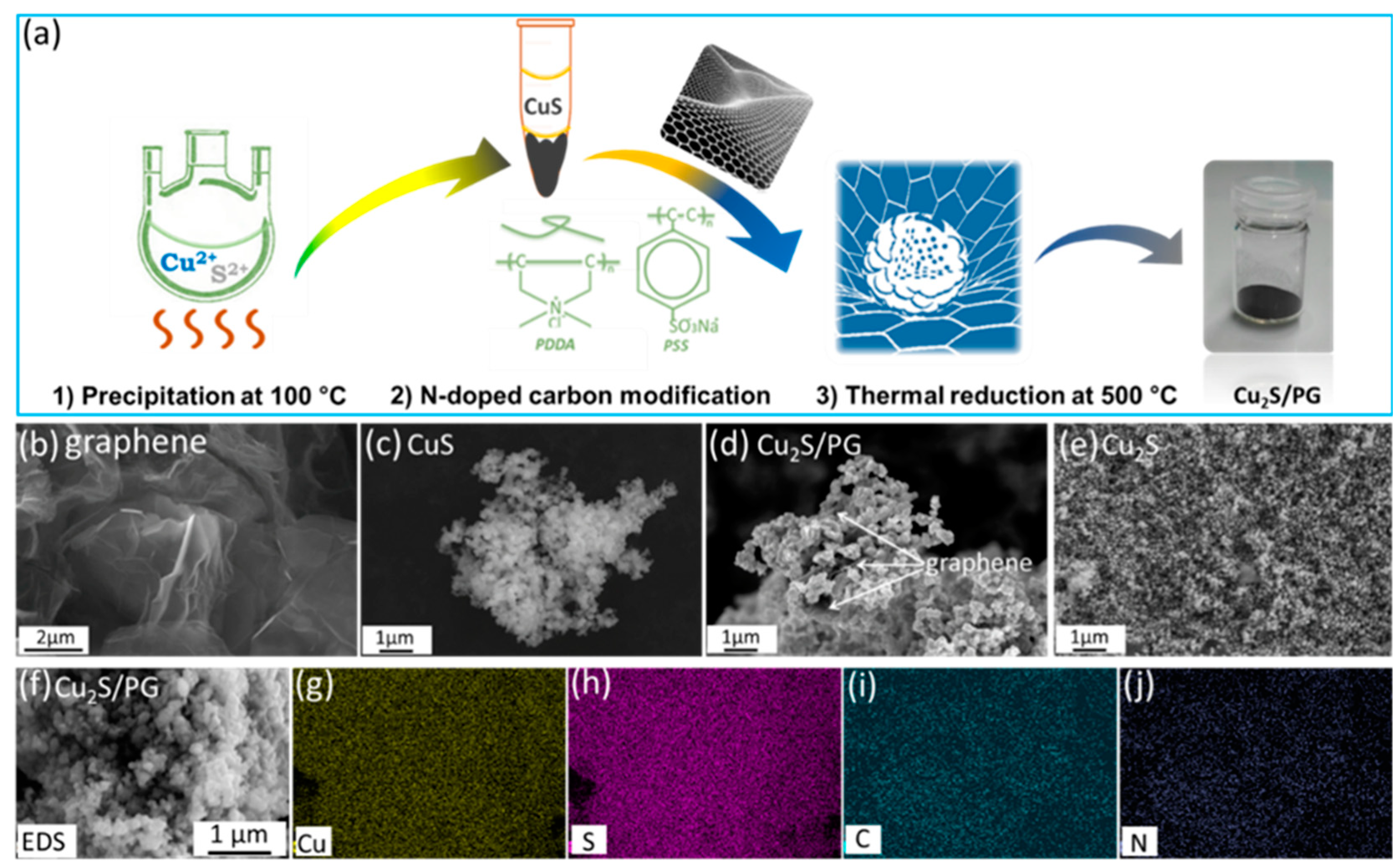
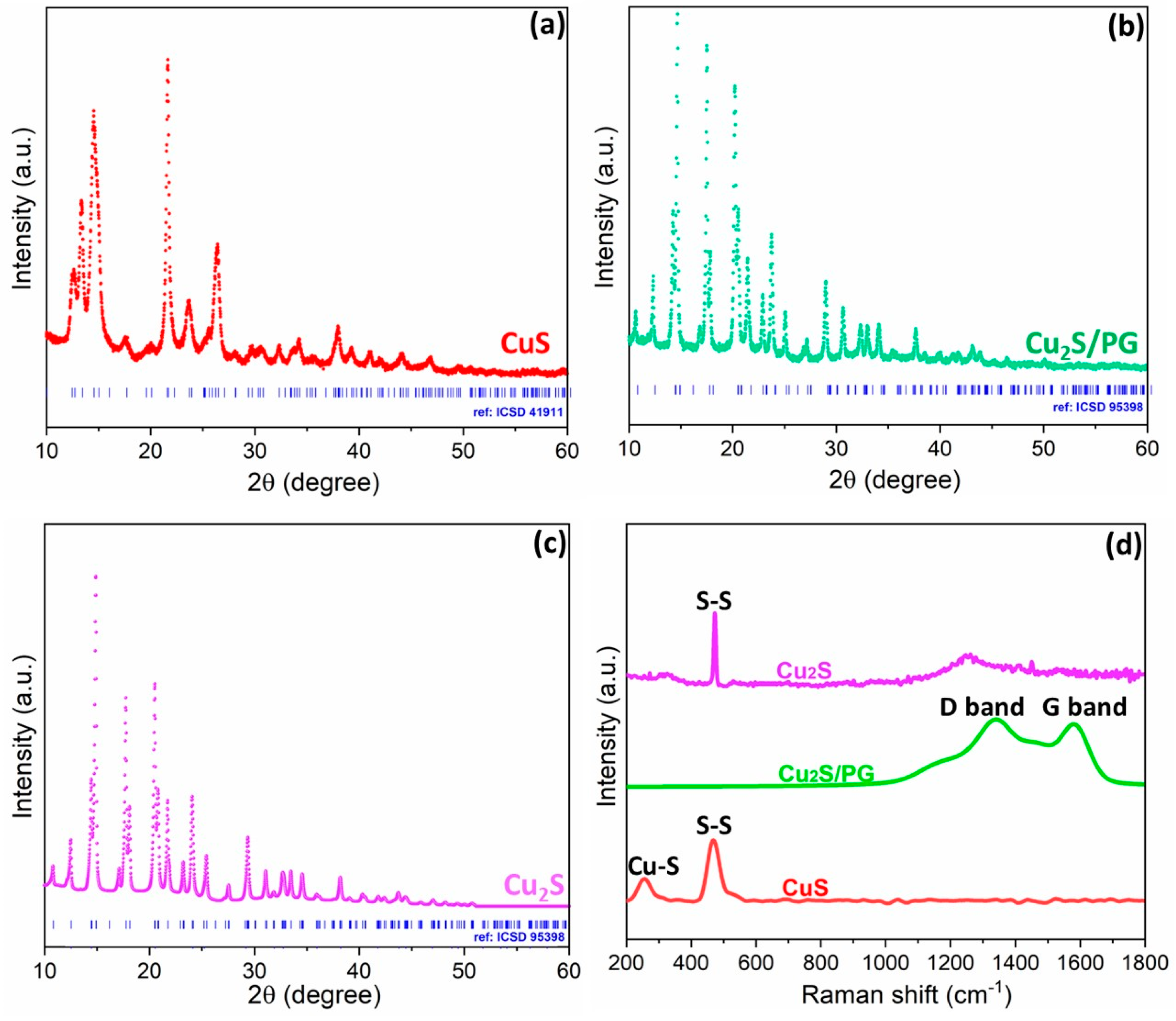
3.1. Synthesis and Characterization of Copper Sulfide Composites

As depicted in Figure 1a, the CuS precursor was prepared by mixing C2H5NS (as a sulfur source, S2−) and Cu2+ in a weak alkaline environment. The Cu2S/PG precursor was obtained through the electrostatic attraction of the CuS precursor, graphene, and polyelectrolytes, followed by thermal reduction during the carbonization process. SEM was conducted to examine the surface morphology of the samples. The graphene exhibits two-dimensional sheets with a wrinkled structure, where the sheet sizes reached at least 20 μm (Figure 1b). Figure 1c shows the stacking of CuS clusters composed of numerous primary nanoparticles (~90 nm). After carbonization, the Cu2S/PG composites display a microstructure consisting of carbon-coated Cu2S nanoparticles loaded onto graphene sheets (Figure 1d). Despite a rougher surface resulting from carbonization, the Cu2S/PG composites maintain the original size of the CuS particles. Figure 1e shows Cu2S nanoparticles prepared through ultrasonic stirring and precipitation reactions, showcasing an average diameter of approximately 60 nm. Additionally, EDS mapping in Figure 1f−j demonstrates the homogeneous distribution of Cu, S, C, and N throughout the Cu2S/PG sample.
XRD analysis (see Figure 2a) reveals that hexagonal CuS belongs to space group P63/mmc (registry no.: ICSD 41911), while the CuS undergoes reduction to Cu2S by the loaded carbon, resulting in the formation of a tetragonal phase (registry no.: ICSD 95398, space group: P43212, as shown in Figure 2b) [25,26]. Additionally, bare Cu2S exhibits the same tetragonal phase as Cu2S/PG, as evident from Figure 2c. The use of carbon modification strategies has been extensively adopted to address inherent issues associated with conversion-type anodes for SIBs [29]. However, the XRD reflections of polyelectrolyte and graphene-coated carbon in Cu2S/PG cannot be observed due to their amorphous structure.
Raman spectra of the prepared samples are presented in Figure 2d. The band observed at approximately 261 cm−1 corresponds to the Cu–S lattice vibration [30], while the band at 466 cm−1 is attributed to S–S stretching (A1g mode), indicating the high crystallinity of CuS and Cu2S [31]. Conversely, in the Cu2S/PG spectrum, the dominant D band and G band associated with carbon are observed at approximately 1321 and 1583 cm−1, respectively. Moreover, the bands related to Cu-S vibration and S-S stretching disappear, suggesting complete coverage of Cu2S particles by loaded carbon [32,33]. Peak fitting analysis of the Cu2S/PG spectrum (Figure S1) indicates a high ratio of G to D bands (IG/ID = 0.88), signifying a substantial proportion of sp2-conjugated carbon. This value exceeds the threshold value for electron-conductive carbon (IG/ID ≥ 0.52) [34]. Consequently, it can be inferred that the carbon layer coating is beneficial to electronic conductivity.
Additionally, X-ray photoelectron spectroscopy (XPS) was employed to investigate the surface chemical composition of Cu2S/PG. Figure S2a indicates two distinct peaks at 952.6 eV and 932.5 eV, attributed to Cu 2p1/2 and Cu 2p3/2 bands, correspondingly. In conjunction with a Cu LMM peak at 917.1 eV, it confirms a +1-valence state of copper within Cu2S/PG, as depicted in Figure S2b [20]. As shown in Figure S2c, the S 2p spectral data have been deconvoluted to six peaks of varying binding energy. They signify the existence of S2−, along with detected impurities such as (S2)2− on the sample’s surface. Figure S2d presents the deconvolution of the C 1s peak into two peaks, ascribed to the preponderance of C-C bonds and the minor presence of C−N bonds. This implies a successful introduction of N atoms into the carbon lattice. Figure S2e shows the N 1s peak deconvoluted into two peaks at 398.9 eV and 400.4 eV, corresponding respectively to pyridinic N and pyrrolic N. This corroborates the successful doping of the N atom from PDDA amine functional groups. Predictably, N-doping aids the electron transfer and electrolyte infiltration in a Cu2S/PG electrode, thereby enhancing the electrochemical performance of Na+ storage [24,35].

3.2. Electrochemical Test

In this study, the as-prepared electrodes were tested in half cells with Na metal serving as the counter electrode. Figure 3a,b illustrate the CV curves of CuS and Cu2S at a scan rate of 0.1 mV s−1. During the initial cycles, multiple electrochemical reactions are evident by several redox peaks. In both samples, the cathodic scan of the first cycle exhibits peaks at 1.7 V and 1.5 V, which are attributed to the Na+ insertion into CuS and Cu2S, respectively [10,36]. Subsequently, the broad peak at approximately 1.1 V is associated with the formation of a solid–electrolyte interphase (SEI) layer [37,38]. The sharp peak around 0.3 V in the CuS sample and peaks below 1.0 V in the Cu2S sample correspond to the conversion reaction to Na2S and Cu. In the subsequent anodic process, the relatively weak peak at around 1.2 V corresponds to Na+ extraction from the loaded carbon. The subsequent anodic peaks at 1.5 V, 1.8 V, and 2.2 V are assigned to the conversion process from Na2S+Cu to CuS during Na+ extraction [37,39]. However, the redox pairs for both samples disappear after five cycles due to the rapid structural failure of the sulfur skeleton and irreversible conversion process [40]. In contrast, the Cu2S/PG sample, which exhibits similar redox peak potentials, demonstrates a relatively stable cycling process. The CV curves in Figure 3c clearly reveal two repeatable redox pairs at 1.5 V vs. 1.6 V and 1.8 V vs. 2.2 V. This stability can be attributed to the modification of Cu2S with N-doped carbon, which suppresses polysulfide shuttling and side reactions with the electrolyte, thus stabilizing the electrode’s surface [7]. Moreover, the incorporation of graphene efficiently enhances the electronic conductivity of the composite Cu2S/PG. Additionally, the surface-controlled charge storage below 0.8 V further contributes to more Na+ storage [41].
The evaluation of the rate capability of prospective electrode materials is significantly crucial for SIBs. This work represents the specific capacities recorded at escalating current densities, which include 0.1, 0.2, 0.5, 1.0, and 2.0 A g−1 (see Figure 3d). When compared to the CuS and Cu2S electrodes, the Cu2S/PG electrode exhibits an enhanced specific capacity. It presents average capacities of 468, 347, 240, 181, and 133 mAh g−1 at ascending current densities. When setting current to its initial density (0.1 A g−1), the Cu2S/PG electrode shows a superior capacity of approximately 491 mAh g−1. Continuingly, the Cu2S/PG electrode was studied using a long-term cyclic test, as displayed in Figure 3e. In the initial twenty cycles, a decrease in the specific capacity is found in the Cu2S/PG electrode, which then becomes a stable capacity within 200 cycles. Herein, the Cu2S/PG electrode exhibits specific capacities of 151 mAh g−1 at 1 A g−1 and 317 mAh g−1 at 0.1 A g−1, respectively. Concurrently, a Coulombic efficiency of over 98% is achieved after fifty cycles. In relation to Table S1, the initial capacity of the Cu2S/PG electrode is not the most impressive among recent CuxS composite anodes for SIBs, while it denotes exceptional potential concerning outstanding cycling stability.

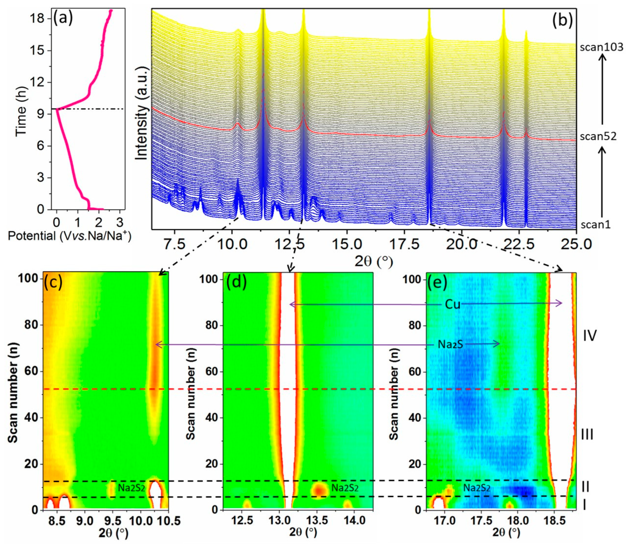
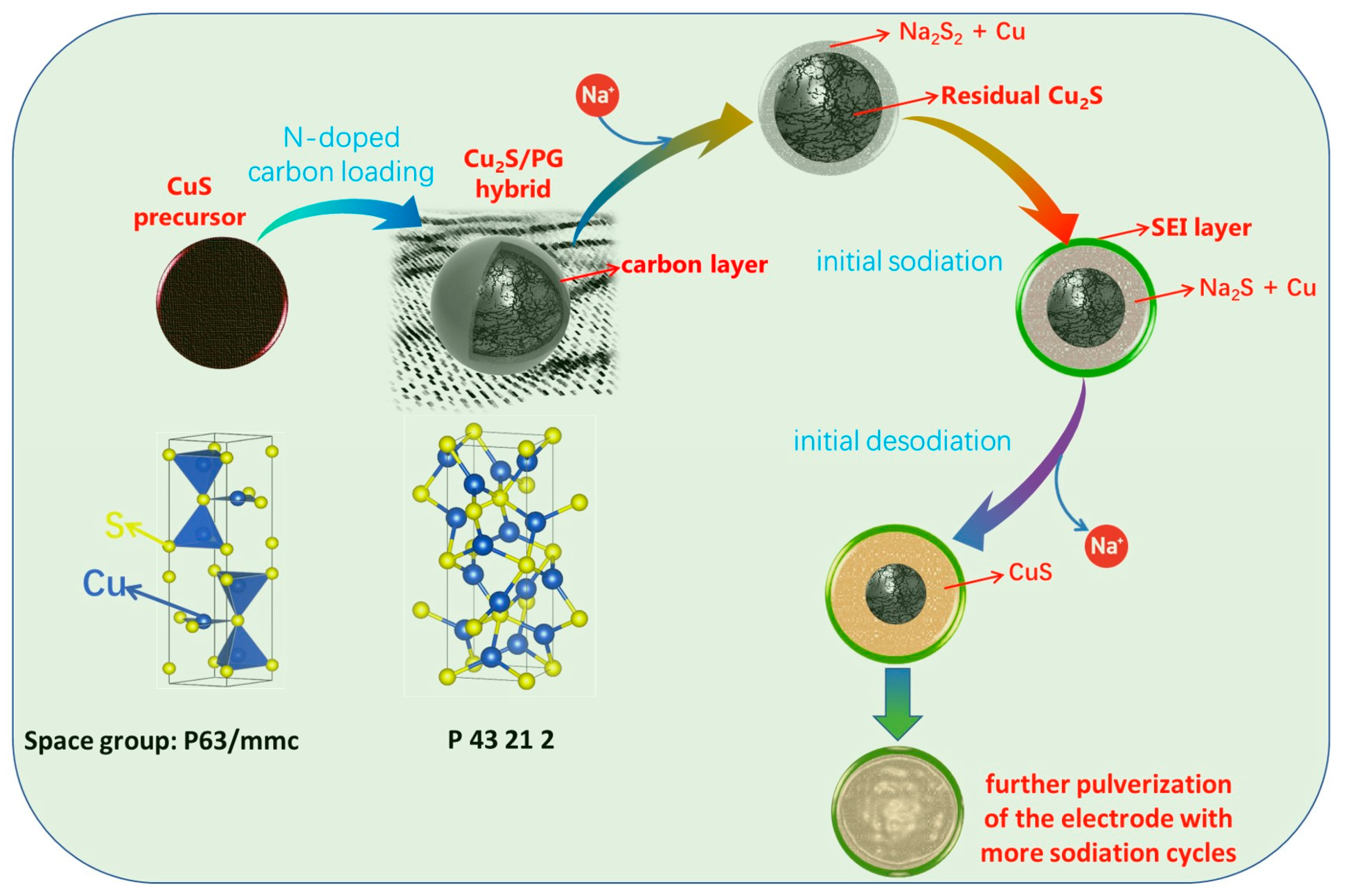
3.3. Mechanism Study for Initial Na+ Storage

In the CV test (see Figure 3c), the Cu2S/PG exhibits a reversible electrochemical process. Previous studies have indicated that the initial cathodic peak in the CV curve was ascribed to the intercalation process of Na+ ions, which was revealed through ex situ XRD analysis [7,42]. Additionally, in situ XRD is a powerful technique for unravelling the phase evolution and electrochemical mechanism during sodiation/desodiation processes. To gain further insights into the Na+ storage mechanism, this work employs in situ XRD measurements with high resolutions for the Cu2S electrode for the first time. The first galvanostatic cycling profile in the potential range of open circuit voltage (OCV)→0.01 V→2.6 V is illustrated in Figure 4a. The corresponding XRD patterns (scan 1−103) are presented in Figure 4b. Based on the transformation of the XRD patterns, the entire process can be roughly divided into four steps (referred to as step I–IV).
In the initial sodiation (OCV-1.4 V, Step I), the XRD diffractions of the Cu2S exhibit a slight left shift, with a gradual intensity decline, and finally disappear by the sixth scan at 1.4 V (Figure 4c–e and Figure S3a). Also, this process shows no emergence of any other new phase. It indicates that Na+ intercalation in the Cu2S structure leads to the expansion and disordering of the Cu2S lattice. Subsequent scans between 1.4 V and 0.9 V (Step II) gradually exhibit new reflections at 7.6°, 9.4°, 10.3°, 13.5°, and 17.1° from the sixth to the thirteenth scan. This evidence hints at the formation of cubic Na2S2 (COD #96-901-6082, see Figure S3b), accompanied by a quick disappearance of residual Cu2S. Concurrently, the reflections at 13.2° and 18.6° become more intense, corresponding to the formation of metallic Cu (see Figure 4d,e). It can be inferred that Na+ prefers to first intercalate into the Cu2S, followed by the conversion process [43]. As such, the preliminary intercalation process plays a vital role in the nanostructural conversion of the Cu2S/PG electrode.
In Step III (Scans 14–52, ranging from 0.9 to 0.01 V), XRD reflections for Na2S begin to emerge once the Na2S2 reflection diminishes, as shown in Figure S3c. Inspired by Bauer’s study [44], Na2S can transition into longer polysulfides (Na2Sx, 4 ≤ x ≤ 8) by a side reaction, which can be dissolved in the electrolyte. In the present research, the occurrence of Na2S2 signals the suppression of polysulfide shuttling, aided by N-doped carbon modification [45]. From the 14th to the 30th scan, no significant changes are witnessed, implying that no discernible transitions in crystalline phases took place. Also, peak diffraction of Cu is found in the entire sodiation process. During the initial desodiation process (Step IV, Scans 53–103, from 0.01 V to 2.6 V as shown in Figure S3d), the reflection intensities for both the generated cubic Cu and Na2S diminish progressively, but they persist until the completion of the desodiation process. This indicates that the transformed metallic Cu particles do not entirely revert to Cu2S, and the residual Cu nanoparticles are scattered in the electrode matrix, thereby enhancing the conductivity. In summary, the initial sodiation/desodiation process, as studied by in situ XRD, can be described in the following steps:
Step I (sodiation—intercalation, OCV~1.4 V):
tetragonal Cu2S + xNa+ + xe → NaxCu2S
Step II (sodiation—conversion, 1.4 V~0.9 V):
NaxCu2S + yNa+ + ye → 0.5(x + y)Na2S2 + Cu
Step III (sodiation—conversion, 0.9 V~0.01 V):
Na2S2 + 2Na+ + 2e → cubic 2Na2S
Step IV (desodiation—conversion, 0.01 V~2.6 V):
cubic Na2S + Cu → CuS + 2e + 2Na+
The discussion of the in situ XRD test indicates that the Na+ insertion/extraction in Cu2S/PG is a multi-step process. To deeply view Na+ diffusion during the electrochemical cycle, in operando EIS data during the initial cycle were analyzed. As depicted in Figure S4, Nyquist plots are drawn based on a three-electrode EL-cell®, wherein a ring-shaped Na reference electrode closely envelopes both the working and counter electrodes. This test cell was (dis)charged at a potential interval of 0.185 V, followed by a stabilization period of 1 h, as seen in Figure S5.
The variation in resistance with the potential interval is primarily influenced by crystal phase transitions and the formation of surficial SEI. In order to elucidate the evolution of resistance during the initial cycle, in operando EIS plots and the corresponding fitted resistances are presented in Figure 5. The applied equivalent circuit used for fitting is illustrated in Figure S6. By analyzing the Nyquist plots in combination with the equivalent circuit, four distinct regions can be identified. The intersection of the plots with the x-axis corresponds to the resistance of the liquid electrolyte, denoted as Rle. The semicircular curve observed in the high-frequency region signifies interface resistance (Rint), which can be further categorized into electrode surface resistance (Rsur) and SEI resistance (RSEI). The semicircle observed in the medium-frequency region can be attributed to the charge transfer resistance (Rct). Finally, the steeply inclined line in the low-frequency region is attributed to Warburg diffusion (Wa), specifically Na+ diffusion within the porous structure of the electrode.
The evolution of fitted resistances is illustrated in Figure S5c and Figure 5f. Initially, Rle exhibits no significant change, suggesting that the electrolyte remains stable during cycling. Regarding Rint, it maintains a modest value of 1–2 Ω, with slight fluctuations during the discharge/charge cycle. Notably, the Rint during the charging cycle is lower than during the discharge cycle. This can be attributed to the facilitation of Na+ diffusion through the interface, due to a compatible SEI layer formed during the discharge cycle. According to a report by J. Zhang et al. [46], the solvated Na+ structure in the NaClO4-EC/PC possesses a high electron cloud density. Furthermore, the surface of N-doped carbon on the CuxS tends to repel Na+ cations and absorb ClO4 anions, which is conducive to promoting the formation of an inorganic-rich SEI (containing Na2O and NaCl), thereby enhancing the interfacial compatibility of the Cu2S/PG electrodes.
Moreover, Rct demonstrates several peak values at approximately 2.0 V, 1.4 V, and 0.6 V during discharge, coinciding with the reduction peaks observed in the CV curve (Figure 3c) and the Na+ insertion processes identified through in situ XRD: Cu2S→NaxCu2S→Na2S2→Na2S, as also confirmed in previous reports [47]. Additionally, the Rct decreases to 0.7 V due to increased electrode conductivity resulting from the accumulation of metallic Cu grains [25]. During the charge process, Rct exhibits high resistance around 1.2 V, which can be attributed to the charge transfer involved in the reversed conversion reaction.
In sum, the proposed mechanism for the Na+ insertion/extraction process in Cu2S/PG is illustrated in Figure 6. In this study, the introduction of N-doped carbon modification assists in stabilizing the surface of the CuxS material, thereby inhibiting polysulfide shuttling between the electrodes and mitigating side reactions with the electrolyte [48]. Furthermore, the incorporation of graphene significantly enhances the electrode’s conductivity. Consequently, the Cu2S/PG electrode exhibits excellent long-term cycling stability.

4. Conclusions

In this study, we successfully prepared a N-doped carbon/graphene-modified Cu2S electrode material for SIBs by employing precipitation and thermal reduction methods. The incorporation of N-doped carbon and graphene layers effectively suppresses polysulfide shuttling, thereby preserving the structural integrity and enhancing the conductivity of the Cu2S particles. Consequently, we observed improved cycling stability in the Cu2S/PG sample compared to the bare Cu2S, which exhibits a sustainable capacity of 257 mAh g−1 after 200 cycles (at a current density of 0.1 A g−1), demonstrating good cycling stability. Furthermore, the Cu2S/PG sample displayed superior rate performance compared to the bare CuS and Cu2S. To gain a comprehensive understanding of the sodiation/desodiation mechanism during the first cycle, we analyzed the phase and structure transformation of Cu2S/PG in SIBs using in situ XRD and in operando EIS techniques. The insights obtained from this analysis contribute to a deeper understanding of the working mechanism of TMS conversion-type materials. Overall, this work provides valuable insights into copper sulphide as a potential electrode material for Na+ storage.

Supplementary Materials

The following supporting information can be downloaded at: https://www.mdpi.com/article/10.3390/su152416846/s1, Figure S1: Raman curve fitted with band combination for the first-order spectrum of the Cu2S/PG; Figure S2: XPS spectra of pristine Cu2S/PG: Cu 2p (a), Cu LMM-2 (b), S 2p (c), C 1s (d), and N 1s (e); Table S1: A review of preparation methods and electrochemical performance of CuxS composites as SIB electrodes; Figure S3: Analysis of typical phase change of the Cu2S/PG electrode in the 1st (de)sodiation for Na+ storage: (a) step I—scan2, (b) step II—scan7, (c) step III—scan50, and (d) step IV—scan70; Figure S4: Nyquist plots obtained from in operando EIS test in the first cycle: 1st discharge process (a) and 1st charge process; Figure S5: Setting potential steps in the EIS measurement for the 1st cycle; Figure S6: Illustration of equivalent circuit for fitting the Nyquist plots. References [49,50,51] are cited in the supplementary materials.

Author Contributions

Conceptualization, G.T. and Z.Z.; methodology, Y.W., G.T. and Z.Z.; software, Z.Z.; validation, J.W.; investigation, X.C., Y.W., G.T. and Z.Z.; resources, J.W.; data curation, J.W.; writing—original draft preparation, G.T. and Z.Z.; writing—review and editing, J.W. and Z.Z.; visualization, X.C. and G.T.; supervision, J.W. and Z.Z.; project administration, J.W. and Z.Z.; funding acquisition, J.W. All authors have read and agreed to the published version of the manuscript.

Funding

The Project is supported by the Foundation (No. BCERE202104) of Tianjin Key Laboratory of Brine Chemical Engineering and Resource Eco-utilization (Tianjin University of Science & Technology). The authors also acknowledge the financial support of this research by the China Postdoctoral Science Foundation (2022M711036), the Key Scientific Research Project Plan of the University in Henan Province (No. 22A430002).

Data Availability Statement

Data are contained within the article and supplementary materials.

Conflicts of Interest

The authors declare no conflict of interest.

References

  1. Narins, T.P. The battery business: Lithium availability and the growth of the global electric car industry. Extr. Ind. Soc. 2017, 4, 321–328. [Google Scholar] [CrossRef]
  2. Deng, W.; Liu, W.; Zhu, H.; Chen, L.; Liao, H.; Chen, H. Click-chemistry and ionic cross-linking induced double cross-linking ionogel electrolyte for flexible lithium-ion batteries. J. Energy Storage 2023, 72, 108509. [Google Scholar] [CrossRef]
  3. Hannan, M.A.; Lipu, M.S.H.; Hussain, A.; Mohamed, A. A review of lithium-ion battery state of charge estimation and management system in electric vehicle applications: Challenges and recommendations. Renew. Sustain. Energy Rev. 2017, 78, 834–854. [Google Scholar] [CrossRef]
  4. Armand, M.; Tarascon, J.-M. Building better batteries. Nature 2008, 451, 652–657. [Google Scholar] [CrossRef] [PubMed]
  5. Deng, W.; Li, Y.; Xu, D.; Zhou, W.; Xiang, K.; Chen, H. Three-dimensional hierarchically porous nitrogen-doped carbon from water hyacinth as selenium host for high-performance lithium–selenium batteries. Rare Met. 2022, 41, 3432–3445. [Google Scholar] [CrossRef]
  6. Hasa, I.; Hassoun, J.; Passerini, S. Nanostructured Na-ion and Li-ion anodes for battery application: A comparative overview. Nano Res. 2017, 10, 3942–3969. [Google Scholar] [CrossRef]
  7. Cai, J.; Reinhart, B.; Eng, P.; Liu, Y.; Sun, C.-J.; Zhou, H.; Ren, Y.; Meng, X. Nitrogen-doped graphene-wrapped Cu2S as a superior anode in sodium-ion batteries. Carbon N. Y. 2020, 170, 430–438. [Google Scholar] [CrossRef]
  8. Chayambuka, K.; Mulder, G.; Danilov, D.L.; Notten, P.H.L. Sodium-Ion Battery Materials and Electrochemical Properties Reviewed. Adv. Energy Mater. 2018, 8, 1800079. [Google Scholar] [CrossRef]
  9. Fan, H.H.; Li, H.H.; Huang, K.C.; Fan, C.Y.; Zhang, X.Y.; Wu, X.L.; Zhang, J.P. Metastable Marcasite-FeS2 as a New Anode Material for Lithium Ion Batteries: CNFs-Improved Lithiation/Delithiation Reversibility and Li-Storage Properties. ACS Appl. Mater. Interfaces 2017, 9, 10708–10716. [Google Scholar] [CrossRef]
  10. Ma, Y.; Ma, Y.; Bresser, D.; Ji, Y.; Geiger, D.; Kaiser, U.; Streb, C.; Varzi, A.; Passerini, S. Cobalt Disulfide Nanoparticles Embedded in Porous Carbonaceous Micro-Polyhedrons Interlinked by Carbon Nanotubes for Superior Lithium and Sodium Storage. ACS Nano 2018, 12, 7220–7231. [Google Scholar] [CrossRef]
  11. Wang, L.; Wang, J.; Guo, F.; Ma, L.; Ren, Y.; Wu, T.; Zuo, P.; Yin, G.; Wang, J. Understanding the initial irreversibility of metal sulfides for sodium-ion batteries via operando techniques. Nano Energy 2018, 43, 184–191. [Google Scholar] [CrossRef]
  12. Zhang, R.; Wang, Y.; Jia, M.; Xu, J.; Pan, E. One-pot hydrothermal synthesis of ZnS quantum dots/graphene hybrids as a dual anode for sodium ion and lithium ion batteries. Appl. Surf. Sci. 2018, 437, 375–383. [Google Scholar] [CrossRef]
  13. Gao, S.; Chen, G.; Dall’Agnese, Y.; Wei, Y.; Gao, Z.; Gao, Y. Flexible MnS-Carbon Fiber Hybrids for Lithium-Ion and Sodium-Ion Energy Storage. Chem.-A Eur. J. 2018, 24, 13535–13539. [Google Scholar] [CrossRef] [PubMed]
  14. Wang, Q.; Zou, R.; Xia, W.; Ma, J.; Qiu, B.; Mahmood, A.; Zhao, R.; Yang, Y.; Xia, D.; Xu, Q. Facile Synthesis of Ultrasmall CoS2 Nanoparticles within Thin N-Doped Porous Carbon Shell for High Performance Lithium-Ion Batteries. Small 2015, 11, 2511–2517. [Google Scholar] [CrossRef] [PubMed]
  15. Qu, B.; Ma, C.; Ji, G.; Xu, C.; Xu, J.; Meng, Y.S.; Wang, T.; Lee, J.Y. Layered SnS2-reduced graphene oxide composite–A high-capacity, high-rate, and long-cycle life sodium-ion battery anode material. Adv. Mater. 2014, 26, 3854–3859. [Google Scholar] [CrossRef] [PubMed]
  16. Foley, S.; Geaney, H.; Bree, G.; Stokes, K.; Connolly, S.; Zaworotko, M.J.; Ryan, K.M. Copper Sulfide (CuxS) Nanowire-in-Carbon Composites Formed from Direct Sulfurization of the Metal-Organic Framework HKUST-1 and Their Use as Li-Ion Battery Cathodes. Adv. Funct. Mater. 2018, 28, 1800587. [Google Scholar] [CrossRef]
  17. Park, H.; Kwon, J.; Choi, H.; Shin, D.; Song, T.; Lou, X.W.D. Unusual Na+ Ion Intercalation/Deintercalation in Metal-Rich Cu1.8S for Na-Ion Batteries. ACS Nano 2018, 12, 2827–2837. [Google Scholar] [CrossRef] [PubMed]
  18. Xiao, Y.; Su, D.; Wang, X.; Wu, S.; Zhou, L.; Shi, Y.; Fang, S.; Cheng, H.-M.; Li, F. CuS Microspheres with Tunable Interlayer Space and Micropore as a High-Rate and Long-Life Anode for Sodium-Ion Batteries. Adv. Energy Mater. 2018, 8, 1800930. [Google Scholar] [CrossRef]
  19. Evans, H.T., Jr. Djurleite (Cu1.94S) and Low Chalcocite (Cu2S): New Crystal Structure Studies. Science 1979, 203, 356–358. [Google Scholar] [CrossRef]
  20. Chen, Q.; Ren, M.; Xu, H.; Liu, W.; Hei, J.; Su, L.; Wang, L. Cu2S@N,S Dual-Doped Carbon Matrix Hybrid as Superior Anode Materials for Lithium/Sodium ion Batteries. ChemElectroChem 2018, 5, 2135–2141. [Google Scholar] [CrossRef]
  21. Liu, Y.; Jin, B.; Zhu, Y.F.; Ma, X.Z.; Lang, X.Y. Synthesis of Cu2S/carbon composites with improved lithium storage performance. Int. J. Hydrogen Energy 2015, 40, 670–674. [Google Scholar] [CrossRef]
  22. Li, J.; Yan, D.; Lu, T.; Qin, W.; Yao, Y.; Pan, L. Significantly Improved Sodium-Ion Storage Performance of CuS Nanosheets Anchored into Reduced Graphene Oxide with Ether-Based Electrolyte. ACS Appl. Mater. Interfaces 2017, 9, 2309–2316. [Google Scholar] [CrossRef] [PubMed]
  23. Xu, D.; Chen, C.; Xie, J.; Zhang, B.; Miao, L.; Cai, J.; Huang, Y.; Zhang, L. A Hierarchical N/S-Codoped Carbon Anode Fabricated Facilely from Cellulose/Polyaniline Microspheres for High-Performance Sodium-Ion Batteries. Adv. Energy Mater. 2016, 6, 1501929. [Google Scholar] [CrossRef]
  24. Ma, Y.; Ma, Y.; Geiger, D.; Kaiser, U.; Zhang, H.; Kim, G.T.; Diemant, T.; Behm, R.J.; Varzi, A.; Passerini, S. ZnO/ZnFe2O4/N-doped C micro-polyhedrons with hierarchical hollow structure as high-performance anodes for lithium-ion batteries. Nano Energy 2017, 42, 341–352. [Google Scholar] [CrossRef]
  25. Tian, G.; Huang, C.; Luo, X.; Zhao, Z.; Peng, Y.; Gao, Y.; Tang, N.; Dsoke, S. Study of the Lithium Storage Mechanism of N-Doped Carbon-Modified Cu2S Electrodes for Lithium-Ion Batteries. Chem.-A Eur. J. 2021, 27, 13774–13782. [Google Scholar] [CrossRef] [PubMed]
  26. Tian, G.; Scheiba, F.; Pfaffmann, L.; Fiedler, A.; Chakravadhanula, V.S.K.; Balachandran, G.; Zhao, Z.; Ehrenberg, H. Electrostatic self-assembly of LiFePO4 cathodes on a three-dimensional substrate for lithium ion batteries. Electrochim. Acta 2018, 283, 1375–1383. [Google Scholar] [CrossRef]
  27. Mousavi-kamazani, M.; Salavati-niasari, M.; Ramezani, M. Preparation and Characterization of Cu2S Nanoparticles Via Ultrasonic Method. J. Clust. Sci. 2013, 24, 927–934. [Google Scholar] [CrossRef]
  28. Rodríguez-Carvajal, J. Recent advances in magnetic structure determination by neutron powder diffraction. Phys. B Condens. Matter 1993, 192, 55–69. [Google Scholar] [CrossRef]
  29. Hwang, J.Y.; Myung, S.T. Sun, Sodium-ion batteries: Present and future. Chem. Soc. Rev. 2017, 46, 3529–3614. [Google Scholar] [CrossRef]
  30. Hurma, T.; Kose, S. XRD Raman analysis and optical properties of CuS nanostructured film. Optik 2016, 127, 6000–6006. [Google Scholar] [CrossRef]
  31. Ishii, M.; Shibata, K.; Nozaki, H. Anion distributions and phase transitions in CuS1−xSex(x = 0–1) studied by raman spectroscopy. J. Solid State Chem. 1993, 105, 504–511. [Google Scholar] [CrossRef]
  32. Bose, S.; Kuila, T.; Uddin, M.E.; Kim, N.H.; Lau, A.K.T.; Lee, J.H. In-situ synthesis and characterization of electrically conductive polypyrrole/graphene nanocomposites. Polymer 2010, 51, 5921–5928. [Google Scholar] [CrossRef]
  33. Bai, J.; Jiang, X. A facile one-pot synthesis of copper sulfide-decorated reduced graphene oxide composites for enhanced detecting of H2O2 in biological environments. Anal. Chem. 2013, 85, 8095–8101. [Google Scholar] [CrossRef] [PubMed]
  34. Sadezky, A.; Muckenhuber, H.; Grothe, H.; Niessner, R.; Pöschl, U. Raman microspectroscopy of soot and related carbonaceous materials: Spectral analysis and structural information. Carbon N. Y. 2005, 43, 1731–1742. [Google Scholar] [CrossRef]
  35. Mao, Y.; Duan, H.; Xu, B.; Zhang, L.; Hu, Y.; Zhao, C.; Wang, Z.; Chen, L.; Yang, Y. Lithium storage in nitrogen-rich mesoporous carbon materials. Energy Environ. Sci. 2012, 5, 7950–7955. [Google Scholar] [CrossRef]
  36. Yu, D.; Li, M.; Yu, T.; Wang, C.; Zeng, Y.; Hu, X.; Chen, G.; Yang, G.; Du, F. Nanotube-assembled pine-needle-like CuS as an effective energy booster for sodium-ion storage. J. Mater. Chem. A 2019, 7, 10619–10628. [Google Scholar] [CrossRef]
  37. Zhao, D.; Yin, M.; Feng, C.; Zhan, K.; Jiao, Q.; Li, H.; Zhao, Y. Rational Design of N-Doped CuS@C Nanowires toward High-Performance Half/Full Sodium-Ion Batteries. ACS Sustain. Chem. Eng. 2020, 8, 11317–11327. [Google Scholar] [CrossRef]
  38. Liu, X.; Li, X.; Lu, X.; He, X.; Jiang, N.; Huo, Y.; Xu, C.; Lin, D. Metal-organic framework derived in-situ nitrogen-doped carbon-encapsulated CuS nanoparticles as high-rate and long-life anode for sodium ion batteries. J. Alloys Compd. 2021, 854, 157132. [Google Scholar] [CrossRef]
  39. Wu, L.; Bresser, D.; Buchholz, D.; Passerini, S. Nanocrystalline TiO2 (B) as Anode Material for Sodium-Ion Batteries. J. Electrochem. Soc. 2014, 162, A3052–A3058. [Google Scholar] [CrossRef]
  40. Zhao, Z.; Tian, G.; Sarapulova, A.; Trouillet, V.; Fu, Q.; Geckle, U.; Ehrenberg, H.; Dsoke, S. Elucidating the energy storage mechanism of ZnMn2O4 as promising anode for Li-ion batteries. J. Mater. Chem. A 2018, 6, 19381–19392. [Google Scholar] [CrossRef]
  41. Zhao, Z.; Tian, G.; Sarapulova, A.; Melinte, G.; Gómez-Urbano, J.L.; Li, C.; Liu, S.; Welter, E.; Etter, M.; Dsoke, S. Mechanism Study of Carbon Coating Effects on Conversion-Type Anode Materials in Lithium-Ion Batteries: Case Study of ZnMn2O4 and ZnO-MnO Composites. ACS Appl. Mater. Interfaces 2019, 11, 29888–29900. [Google Scholar] [CrossRef] [PubMed]
  42. Yan, B.; Li, Y.; Zhang, L.; Yang, X. Hollow heterostructured Cu1.96S/NiS microspheres coupled with nitrogen/sulfur dual-doped carbon realizing superior reaction kinetics and sodium storage. New J. Chem. 2023, 47, 14746–14757. [Google Scholar] [CrossRef]
  43. Cabana, J.; Monconduit, L.; Larcher, D.; Palacín, M.R. Beyond Intercalation-Based Li-Ion Batteries: The State of the Art and Challenges of Electrode Materials Reacting Through Conversion Reactions. Adv. Mater. 2010, 22, E170–E192. [Google Scholar] [CrossRef] [PubMed]
  44. Bauer, I.; Kohl, M.; Althues, H.; Kaskel, S. Shuttle suppression in room temperature sodium–sulfur batteries using ion selective polymer membranes. Chem. Commun. 2014, 50, 3208. [Google Scholar] [CrossRef] [PubMed]
  45. Tian, G.; Zhao, Z.; Sarapulova, A.; Das, C.; Zhu, L.; Liu, S.; Missiul, A.; Welter, E.; Maibach, J.; Dsoke, S. Understanding the Li-ion storage mechanism in a carbon composited zinc sulfide electrode. J. Mater. Chem. A 2019, 7, 15640–15653. [Google Scholar] [CrossRef]
  46. Zhang, J.; Meng, Z.; Yang, D.; Song, K.; Mi, L.; Zhai, Y.; Guan, X.; Chen, W. Enhanced interfacial compatibility of FeS@N,S-C anode with ester-based electrolyte enables stable sodium-ion full cells. J. Energy Chem. 2022, 68, 27–34. [Google Scholar] [CrossRef]
  47. Pan, Q.; Zhang, M.; Zhang, L.; Li, Y.; Li, Y.; Tan, C.; Zheng, F.; Huang, Y.; Wang, H.; Li, Q. FeSe2@C Microrods as a Superior Long-Life and High-Rate Anode for Sodium Ion Batteries. ACS Nano 2020, 14, 17683–17692. [Google Scholar] [CrossRef]
  48. Yan, B.; Feng, L.; Zheng, J.; Zhang, Q.; Zhang, C.; Ding, Y.; Han, J.; Jiang, S.; He, S. In situ growth of N/O-codoped carbon nanotubes in wood-derived thick carbon scaffold to boost the capacitive performance. Colloids Surf. A Physicochem. Eng. Asp. 2023, 662, 131018. [Google Scholar] [CrossRef]
  49. Kim, N.R.; Choi, J.; Yoon, H.J.; Lee, M.E.; Son, S.U.; Jin, H.J.; Yun, Y.S. Conversion Reaction of Copper Sulfide Based Nanohybrids for Sodium-Ion Batteries. ACS Sustain. Chem. Eng. 2017, 5, 9802–9808. [Google Scholar] [CrossRef]
  50. Tao, H.; Tang, Y.; Zhou, M.; Wang, R.; Wang, K.; Li, H.; Jiang, K. Porous Copper Sulfide Microflowers Grown In Situ on Commercial Copper Foils as Advanced Binder-Free Electrodes with High Rate and Long Cycle Life for Sodium-Ion Batteries. ChemElectroChem 2021, 8, 157–163. [Google Scholar] [CrossRef]
  51. Kim, H.; Sadan, M.K.; Kim, C.; Choe, S.H.; Cho, K.K.; Kim, K.W.; Ahn, J.H.; Ahn, H.J. Simple and scalable synthesis of CuS as an ultrafast and long-cycling anode for sodium ion batteries. J. Mater. Chem. A 2019, 7, 16239–16248. [Google Scholar] [CrossRef]
Figure 1. (a) Preparation illustration of the Cu2S/PG; (be) SEM images of (b) graphene, (c) CuS, (d) Cu2S/PG, (e) Cu2S; and EDS elemental mapping (fj) of the Cu2S/PG (Cu, S, C and N).
Sustainability 15 16846 g001
Figure 2. (ac) XRD patterns of (a) CuS, (b) Cu2S/PG, and (c) Cu2S; (d) Raman spectra of CuS, Cu2S/PG, and Cu2S.
Sustainability 15 16846 g002
Figure 3. CV curves of (a) CuS, (b) Cu2S/PG, and (c) Cu2S (scan rate: 0.1 mV s−1); (d) electrochemical rate performance of the CuS, Cu2S/PG, and Cu2S; and (e) long-term cycling test for the Cu2S/PG at different current densities.
Sustainability 15 16846 g003
Figure 4. In situ XRD test for the Cu2S/PG sample in a half cell: (a) the potential profile during the 1st cycling at 80 mA g−1, (b) the XRD patterns during the 1st cycling, and (ce) the contour maps of the enlarged regions of the XRD patterns.
Sustainability 15 16846 g004
Figure 5. Analysis of Nyquist plots achieved from in operando EIS test in the 1st cycle: (a) discharge 2.50–1.39 V, (b) discharge 1.20–0.01 V, (c) resistances evolution in the 1st discharge process; (d) charge 0.09–1.20 V, (e) charge 1.39–2.50 V, (f) resistances evolution in the 1st charge process.
Sustainability 15 16846 g005
Figure 6. Schematic illustration of the structural and phase evolution of the Cu2S/PG during the initial cycles.
Sustainability 15 16846 g006
Disclaimer/Publisher’s Note: The statements, opinions and data contained in all publications are solely those of the individual author(s) and contributor(s) and not of MDPI and/or the editor(s). MDPI and/or the editor(s) disclaim responsibility for any injury to people or property resulting from any ideas, methods, instructions or products referred to in the content.

