
A Comprehensive Review of the Applications of Hybrid Evaporative Cooling and Solar Energy Source Systems

 ,
,
Abstract
:1. Introduction
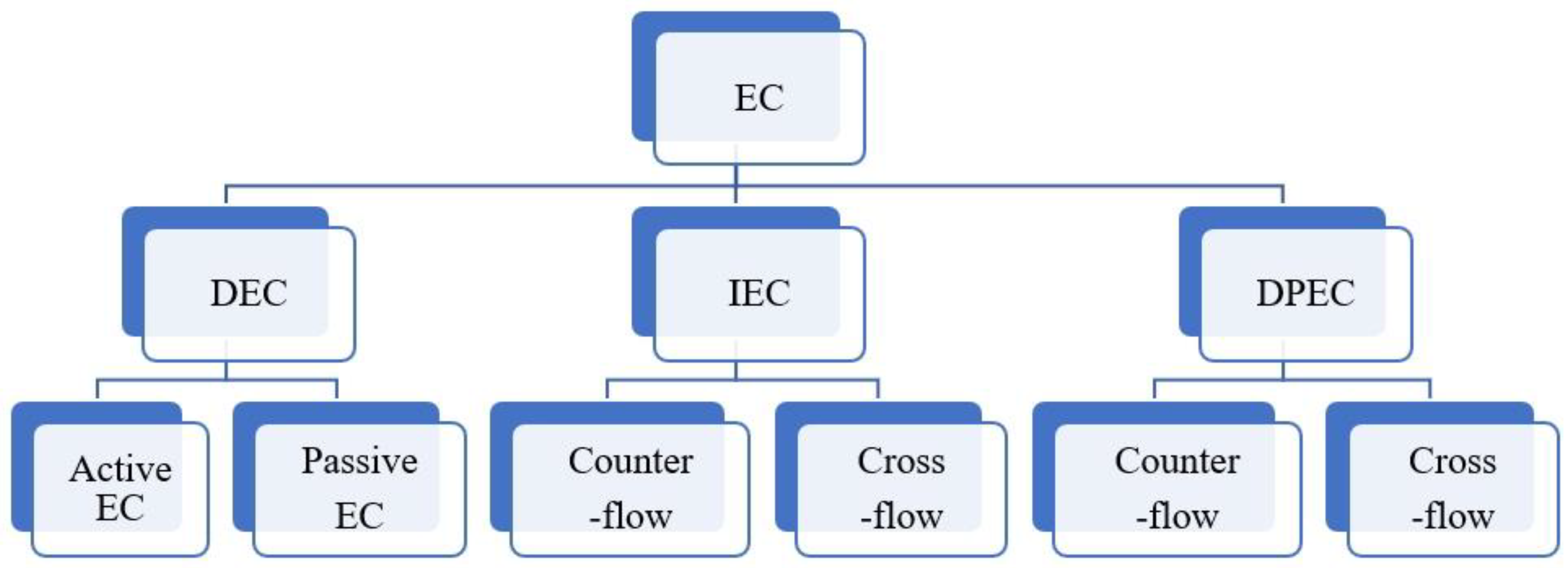
2. Classifications and Principles of EC
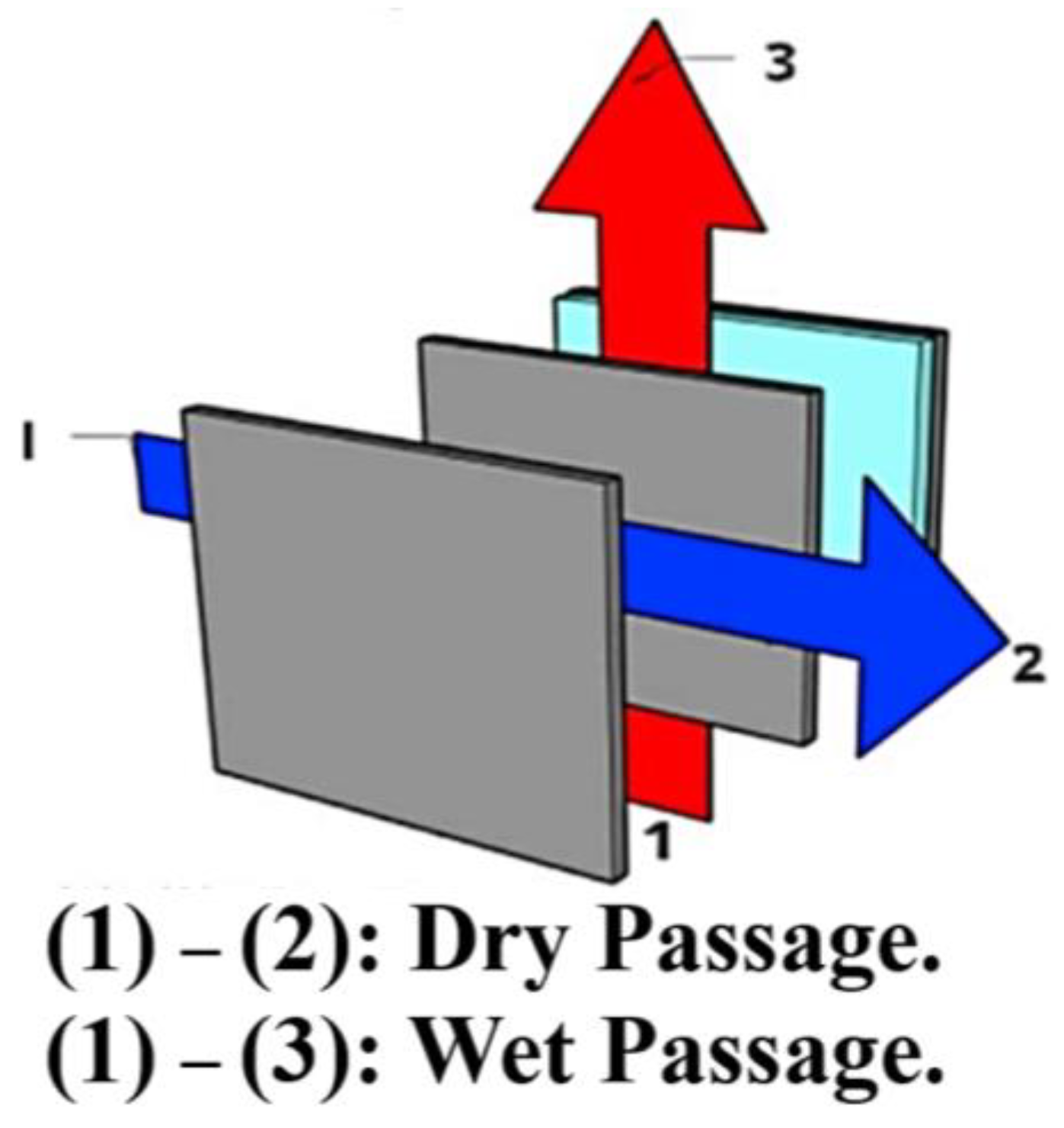
2.1. DEC
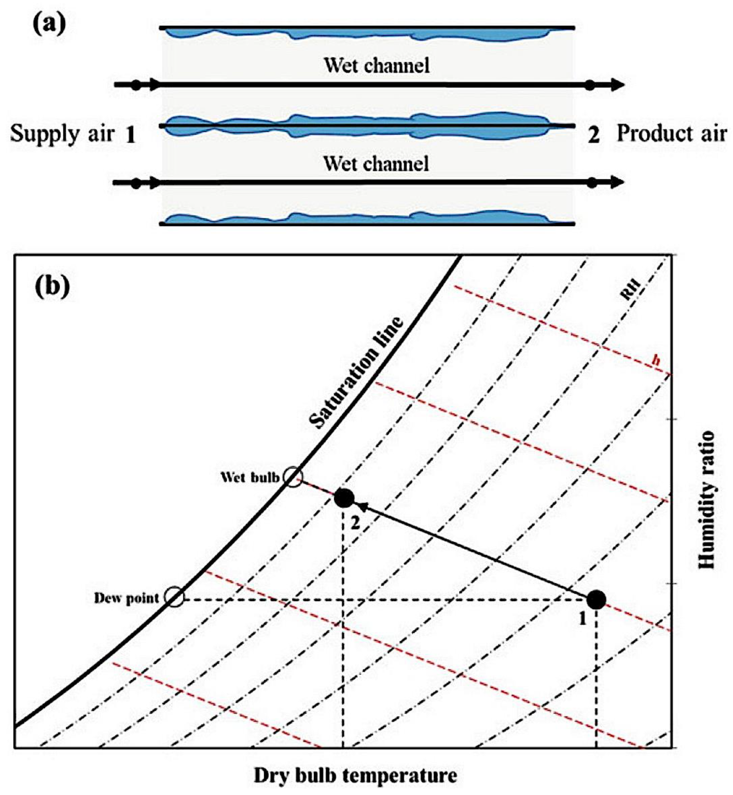
2.2. IEC
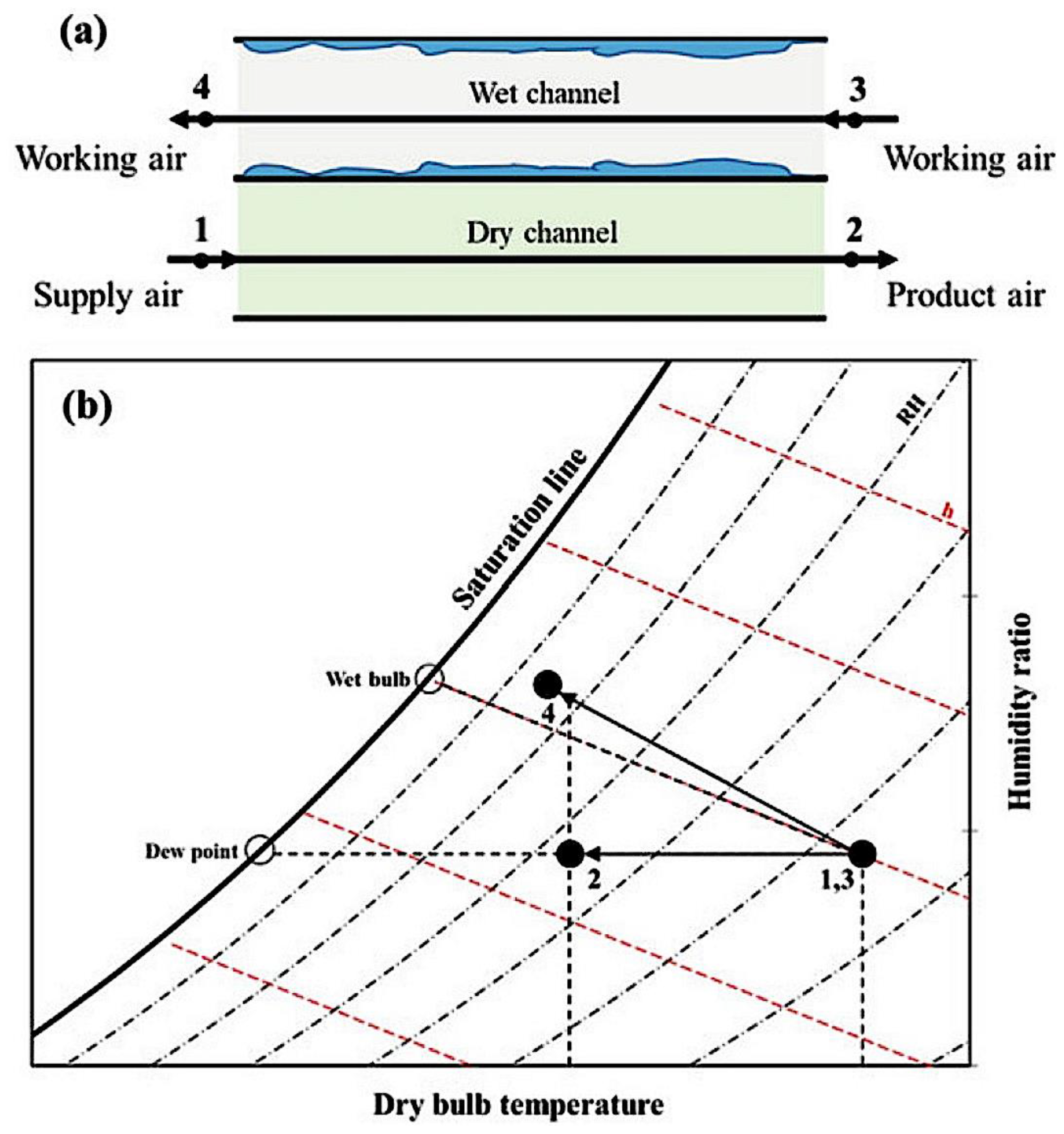
2.3. DPEC
2.4. Evaluation Indices
2.5. Mathematical Approach
3. Mathematical Model of Solar Energy
3.1. Solar Power Generation
3.2. Solar Thermal Collector
4. Hybrid EC and SE Systems
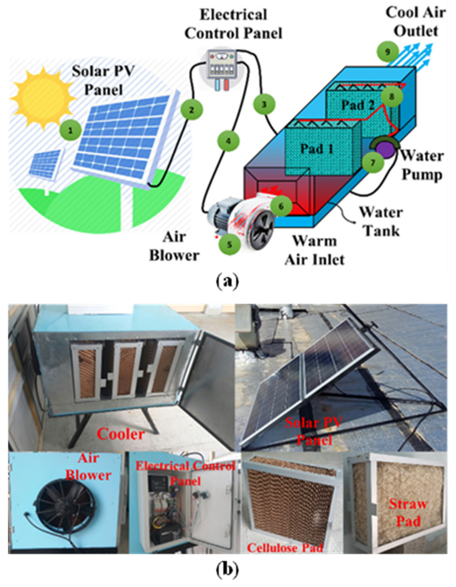
4.1. EC Integrated with Solar Power Generation
4.2. EC Integrated with Solar Thermal Energy
4.2.1. Integration of EC with Solar Collector
4.2.2. Integration of EC with Solar Chimney
5. Current Research Gaps and Potential Future Research Opportunities
5.1. Current Research Gaps
5.2. Potential Future Research Opportunities
6. Conclusions
- (1)
- EC–SE systems encompass various types. SC systems are primarily used in buildings. Studies on PV power generation and solar drying should consider the 3E problem;
- (2)
- Among various EC–SE systems, the majority utilize the DEC configuration, followed closely by the IEC configuration. These configurations are primarily employed to generate cool air and maintain thermal comfort conditions;
- (3)
- Studies on solar–EC systems have matured, demonstrating the potential to achieve human comfort conditions in hybrid systems. Augmenting the SPV capacity of EC systems has been identified as a method to enhance both cooling performance and power output;
- (4)
- There are two main approaches to heat convection and solar power generation in SE. These approaches result in minor differences in the system’s output temperature. However, efficiency and exergoeconomic considerations need to be taken into account; and
- (5)
- While EC–SE systems may not be as efficient as traditional AC due to solar intermittency, their long-term operating life and lower economic cost make them an attractive choice.
Author Contributions
Funding
Institutional Review Board Statement
Informed Consent Statement
Data Availability Statement
Conflicts of Interest
References
- NOAA National Centers for Environmental Information, Climate at a Glance: Global Time Series. Available online: https://www.ncei.noaa.gov/access/monitoring/climate-at-a-glance/global/time-series (accessed on 10 June 2023).
- Marquardt, J.; Fünfgeld, A.; Elsässer, J.P. Institutionalizing climate change mitigation in the Global South: Current trends and future research. Earth Syst. Gov. 2023, 15, 100163. [Google Scholar] [CrossRef]
- Sheng, Z.; Ocłon, P.; Klemeš, J.J.; Michorczyk, P.; Pielichowska, K.; Pielichowski, K. Renewable energy systems for building heating, cooling and electricity production with thermal energy storage. Renew. Sustain. Energy Rev. 2022, 165, 112560. [Google Scholar]
- Song, K.H.; Baiocchi, G.; Feng, K.S.; Hubacek, K.; Sun, L.X. Unequal household carbon footprints in the peak-and-decline pattern of U.S. greenhouse gas emissions. J. Clean. Prod. 2022, 368, 132650. [Google Scholar] [CrossRef]
- Li, H.H.; Mahmud, M.A.; Arzaghi, E.; Abbassi, R.; Chen, D.Y.; Xu, B.B. Assessments of economic benefits for hydro-wind power systems: Development of advanced model and quantitative method for reducing the power wastage. J. Clean. Prod. 2020, 277, 123823. [Google Scholar] [CrossRef]
- Mao, M.X.; Zhang, L.; Huang, H.; Chong, B.; Zhou, L. Maximum power exploitation for grid-connected PV system under fast-varying solar irradiation levels with modified salp swarm algorithm. J. Clean. Prod. 2020, 268, 122158. [Google Scholar] [CrossRef]
- Wang, M.; Peng, J.Q.; Luo, Y.M.; Shen, Z.C.; Yang, H.X. Comparison of different simplistic prediction models for forecasting PV power output: Assessment with experimental measurements. Energy 2021, 224, 120162. [Google Scholar] [CrossRef]
- Ghussain, L.A.; Ahmad, A.D.; Abubaker, A.M.; Hassan, M.A. Exploring the feasibility of green hydrogen production using excess energy from a country-scale 100% solar-wind renewable energy system. Int. J. Hydrogen Energy 2022, 47, 21613–21633. [Google Scholar] [CrossRef]
- Kan, A.K.; Zeng, Y.L.; Meng, X.Y.; Wang, D.; Xina, J.; Yang, X.; Tesren, L. The linkage between renewable energy potential and sustainable development: Understanding solar energy variability and photovoltaic power potential in Tibet, China. Sustain. Energy Technol. Assess. 2021, 48, 101551. [Google Scholar] [CrossRef]
- Reveshti, A.M.; Ebrahimpour, A.; Razmara, J. Investigating the effect of new and old weather data on the energy consumption of buildings affected by global warming in different climates. Int. J. Thermofluids 2023, 19, 100377. [Google Scholar] [CrossRef]
- Diana, Ü.V.; Cabeza, L.F.; Serrano, S.; Barreneche, C.; Petrichenko, K. Heating and cooling energy trends and drivers in buildings. Renew. Sustain. Energy Rev. 2015, 41, 85–98. [Google Scholar]
- Luis, P.L.; Ortiz, J.; Pout, C. A review on buildings energy consumption information. Energy Build. 2008, 40, 394–398. [Google Scholar]
- Lin, J.; Chua, K.J. Indirect Dew-Point Evaporative Cooling: Principles and Applications; Green Energy and Technology; Springer Science and Business Media LLC: Dordrecht, The Netherlands, 2023. [Google Scholar]
- Sajjad, U.; Abbas, N.; Hamid, K.; Abbas, S.; Hussain, I.; Ammar, S.M.; Sultan, M.; Ali, H.M.; Hussain, M.; Rehman, T.U.; et al. A review of recent advances in indirect evaporative cooling technology. Int. Commun. Heat. Mass. Transf. 2021, 122, 105140. [Google Scholar] [CrossRef]
- Abdullah, S.; Zubir, M.N.B.M.; Muhamad, M.R.B.; Newaz, K.M.S.; Öztop, H.F.; Alam, M.S.; Shaikh, K. Technological development of evaporative cooling systems and its integration with air dehumidification processes: A review. Energy Build. 2023, 283, 112805. [Google Scholar] [CrossRef]
- Shahzad, M.W.; Lin, J.; Xu, B.B.; Dala, L.; Chen, Q.; Burhan, M.; Sultan, M.; Worek, W.; Ng, K.C. A spatiotemporal indirect evaporative cooler enabled by transiently interceding water mist. Energy 2021, 217, 119352. [Google Scholar] [CrossRef]
- Sohani, A.; Zabihigivi, M.; Moradi, M.H.; Sayyaadi, H.; Balyani, H.H. A comprehensive performance investigation of cellulose evaporative cooling pad systems using predictive approaches. Appl. Therm. Eng. 2017, 110, 1589–1608. [Google Scholar] [CrossRef]
- Abbassi, A.; Aliehyaei, M. Exergy method of optimisation of a wavy plate indirect evaporative cooler. Int. J. Exergy 2004, 1, 350–362. [Google Scholar] [CrossRef]
- Glanville, P.; Kozlov, A.; Maisotsenko, V. Dew point evaporative cooling: Technology review and fundamentals. Ashrae Trans. 2011, 117, 111–118. [Google Scholar]
- Cuce, E.; Cuce, P.M. A comprehensive review on solar cookers. Appl. Energy 2013, 102, 1399–1421. [Google Scholar] [CrossRef]
- Bishoyi, D.; Sudhakar, K. Experimental performance of a direct evaporative cooler in composite climate of India. Energy Build. 2017, 153, 190–200. [Google Scholar] [CrossRef]
- Dağtekin, M.; Karaca, C.; Sangün, L.; Yildiz, Y. Determination of the relationship among air velocity, cooling efficiency and temperature decrease at a cellulose based evaporative cooling pad. Afr. J. Agric. Res. 2010, 5, 3477–3482. [Google Scholar]
- Mahmood, M.H.; Sultan, M.; Miyazaki, T.; Koyama, S.; Maisotsenko, V.S. Overview of the Maisotsenko cycle–A way towards dew point evaporative cooling. Renew. Sustain. Energy Rev. 2016, 66, 537–555. [Google Scholar] [CrossRef]
- Zhang, Y.; Zhang, H.; Yang, H.; Chen, Y.; Leung, C.W. Counter-crossflow indirect evaporative cooling-assisted liquid desiccant dehumidifier: Model development and parameter analysis. Appl. Therm. Eng. 2022, 217, 119231. [Google Scholar] [CrossRef]
- Bleibel, N.; Ismail, N.; Ghaddar, N.; Ghali, K. Solar-assisted desiccant dehumidification system to improve performance of evaporatively cooled window in hot and-humid climates. Appl. Therm. Eng. 2020, 179, 115726. [Google Scholar] [CrossRef]
- Yang, Y.; Cui, G.; Lan, C.Q. Developments in evaporative cooling and enhanced evaporative cooling-A review. Renew. Sustain. Energy Rev. 2019, 113, 109230. [Google Scholar] [CrossRef]
- Wang, J.; Lu, J.; Li, W.; Zeng, C.; Shi, F. Numerical study on performance of a hybrid indirect evaporative cooling heat recovery heat pump ventilator as applied in different climatic regions of China. Energy 2022, 239, 12243. [Google Scholar] [CrossRef]
- Youssef, R.; Hosen, M.S.; He, J.C.; Jaguemont, J.; Sutter, L.D.; Mierlo, J.V.; Berecibar, M. Effect analysis on performance enhancement of a novel and environmental evaporative cooling system for lithium-ion battery applications. J. Energy Storage 2021, 37, 102475. [Google Scholar] [CrossRef]
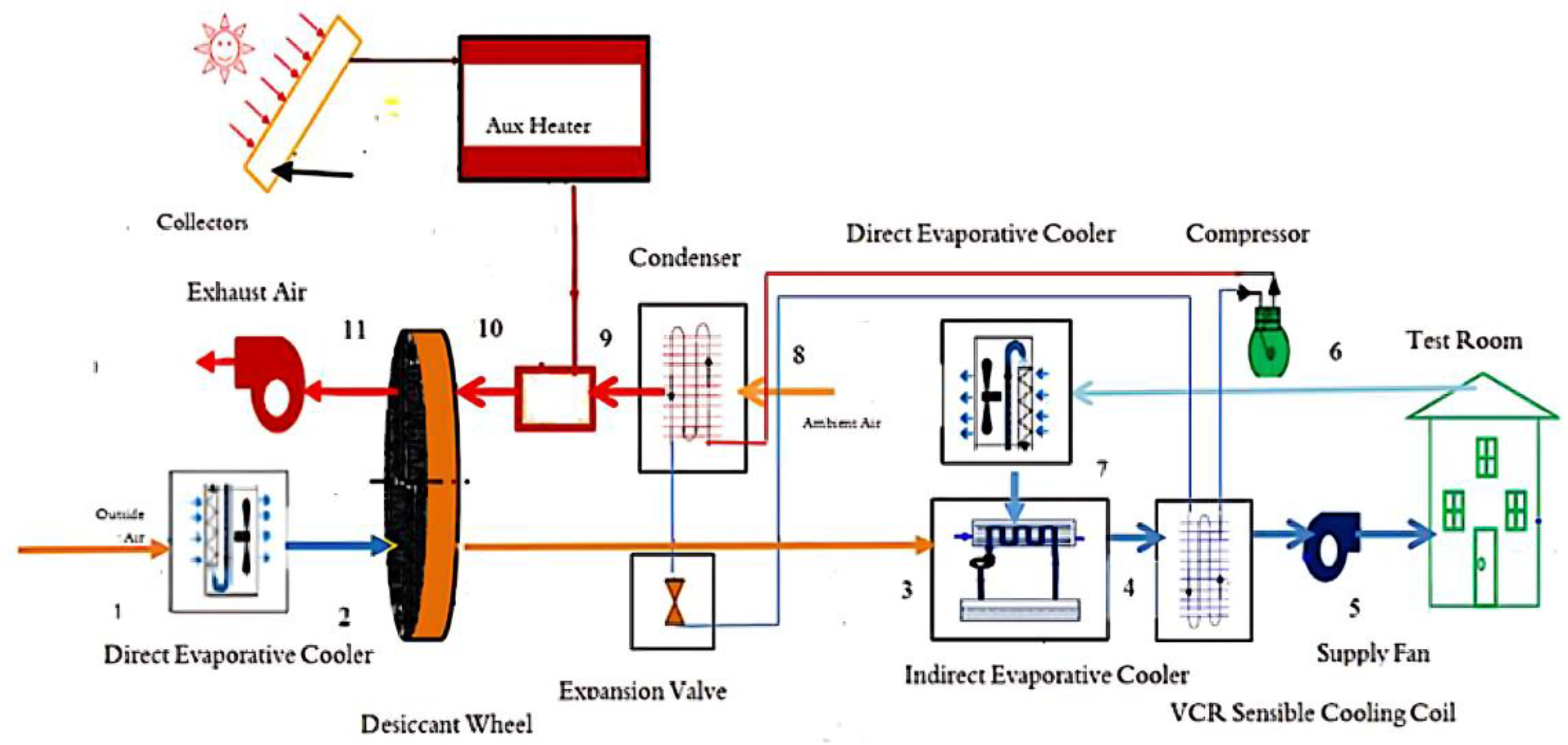
- Chen, Q.; Ja, M.K.; Burhan, M.; Shahzad, M.W.; Ybyraiymkul, D.; Zheng, H.; Ng, K.C. Experimental study of a sustainable cooling process hybridizing indirect evaporative cooling and mechanical vapor compression. Energy Rep. 2022, 8, 7945–7956. [Google Scholar] [CrossRef]
- Kabeel, A.; Abdelgaied, M.; Sathyamurthy, R.; Arunkumar, T. Performance improvement of a hybrid air conditioning system using the indirect evaporative cooler with internal baffles as a pre-cooling unit. Alex. Eng. J. 2017, 56, 395–403. [Google Scholar] [CrossRef]
- Bilen, K.; Erdoğan, İ. Effects of cooling on performance of photovoltaic/thermal (PV/T) solar panels: A comprehensive review. Sol. Energy 2023, 262, 111829. [Google Scholar] [CrossRef]
- Mahdi, A.H.; Aljubury, I.M.A. Experimental investigation of two-stage evaporative cooler powered by photovoltaic panels using underground water. J. Build. Eng. 2021, 44, 102679. [Google Scholar] [CrossRef]
- Sheik, M.S.; Kakati, P.; Dandotiya, D.; Ravi, M.U.; Ramesh, C.S. A comprehensive review on various cooling techniques to decrease an operating temperature of solar photovoltaic panels. Energy Nexus 2022, 8, 100161. [Google Scholar] [CrossRef]
- Almasri, R.A.; Abu-Hamdeh, N.H.; Esmaeil, K.K.; Suyambazhahan, S. Thermal solar sorption cooling systems-A review of principle, technology, and applications. Alex. Eng. J. 2022, 61, 367–402. [Google Scholar] [CrossRef]
- Dake, R.A.; N’Tsoukpoe, K.E.; Lèye, B.; Ouédraogo, I.W.K.; Kuznik, B. A review on the use of sorption materials in solar dryers. Renew. Energy 2021, 175, 965–979. [Google Scholar] [CrossRef]
- Hasan, M.M.; Agili, B.; Zaman, I.; He, M.; Giesselmann, M. Freshwater Production Towards Microgrid Integration: Physics, Progress, and Prospects of Solar-Thermal Evaporation. Clean. Energy Syst. 2022, 3, 100037. [Google Scholar] [CrossRef]
- Kapilan, N.; Isloor, A.M.; Karinka, S. A comprehensive review on evaporative cooling systems. Results Eng. 2023, 18, 101059. [Google Scholar] [CrossRef]
- Lechner, N. Heating, Cooling, Lighting: Sustainable Design Methods for Architects, 3rd ed.; Wiley: Hoboken, NJ, USA, 2009; Volume 10, pp. 276–293. [Google Scholar]
- Kolokotsa, D.; Santamouris, M.; Synnefa, A.; Karlessi, T. Passive solar architecture. Compr. Renew. Energy 2012, 3, 637–665. [Google Scholar]
- Duan, Z.; Zhan, C.; Zhang, X.; Mustafa, M.; Zhao, X.; Alimohammadisagvand, B.; Hasan, A. Indirect evaporative cooling: Past, present and future potentials. Renew. Sustain. Energy Rev. 2012, 16, 6823–6850. [Google Scholar] [CrossRef]
- Tariq, R.; Sheikh, N.A.; Xamán, J.; Bassam, A. Recovering waste energy in an indirect evaporative cooler—A case for combined space air conditioning for human occupants and produce commodities. Build. Environ. 2019, 152, 105–121. [Google Scholar] [CrossRef]
- Chengqin, R.; Hongxing, Y. An analytical model for the heat and mass transfer processes in indirect evaporative cooling with parallel/counter flow configurations. Int. J. Heat Mass Transf. 2006, 49, 617–627. [Google Scholar] [CrossRef]
- Riangvilaikul, B.; Kumar, S. An experimental study of a novel dew point evaporative cooling system. Energy Build. 2010, 42, 637–644. [Google Scholar] [CrossRef]
- Maisotsenko, V.; Reyzin, I. The Maisotsenko cycle for electronics cooling. In Proceedings of the International Electronic Packaging Technical Conference and Exhibition, San Francisco, CA, USA, 17–22 July 2005; Volume 42002, pp. 415–424. [Google Scholar]
- Lin, J.; Chu, H.N.; Thu, K.; Wojtala, M.; Gao, F.; Chua, K.J. Novel battery thermal management via scalable dew-point evaporative cooling. Energy Convers. Manag. 2023, 283, 116948. [Google Scholar] [CrossRef]
- Jon, C.K.; Islam, M.R.; Choon, N.K.; Shahzad, M.W. Advances in Air Conditioning Technologies: Improving Energy Efficiency; Springer: Singapore, 2021. [Google Scholar]
- Sohani, A.; Sayyaadi, H.; Hoseinpoori, S. Modeling and multi-objective optimization of an M-cycle cross-flow indirect evaporative cooler using the GMDH type neural network. Int. J. Refrig. 2016, 69, 186–204. [Google Scholar] [CrossRef]
- Lin, J.; Thu, K.; Bui, T.; Wang, R.; Ng, K.C.; Kumja, M.; Chua, K. Unsteady-state analysis of a counter-flow dew point evaporative cooling system. Energy 2016, 113, 172–185. [Google Scholar] [CrossRef]
- Cui, Y.; Zhu, J.; Zoras, S.; Liu, L. Review of the recent advances in dew point evaporative cooling technology: 3E (energy, economic and environmental) assessments. Renew. Sustain. Energy Rev. 2021, 148, 111345. [Google Scholar] [CrossRef]
- Duan, Z.; Zhao, X.; Zhan, C.; Dong, X.; Chen, H. Energy saving potential of a counter-flow regenerative evaporative cooler for various climates of China: Experiment-based evaluation. Energy Build. 2017, 148, 199–210. [Google Scholar] [CrossRef]
- Park, J.Y.; Kim, B.J.; Yoon, S.Y.; Byon, Y.S.; Jeong, J.W. Experimental analysis of dehumidification performance of an evaporative cooling-assisted internally cooled liquid desiccant dehumidifier. Appl. Energy 2019, 235, 177–185. [Google Scholar] [CrossRef]
- Cho, H.J.; Cheon, S.Y.; Jeong, J.W. Experimental analysis of dehumidification performance of counter and cross-flow liquid desiccant dehumidifier. Appl. Therm. Eng. 2019, 150, 210–223. [Google Scholar] [CrossRef]
- Ndukwu, M.C.; Ibeh, M.I.; Akpan, G.E.; Ugwu, E.; Akuwueke, L.; Oriaku, L.; Ihediwa, V.E.; Abam, F.I.; Wu, H.W.; Kalu, C.A.; et al. Analysis of the influence of outdoor surface heat flux on the inlet water and the exhaust air temperature of the wetting pad of a direct evaporative cooling system. Appl. Therm. Eng. 2023, 226, 120292. [Google Scholar] [CrossRef]
- Zhao, X.; Li, J.M.; Riffat, S.B. Numerical study of a novel counter-flow heat and mass exchanger for dew point evaporative cooling. Appl. Therm. Eng. 2008, 28, 1942–1951. [Google Scholar] [CrossRef]
- Zhao, X. Optimal Study of the Heat and Mass Exchanger in an Innovative Evaporative Cooling System, Case for Support to the New Researchers’ Fund; University of Nottingham: Nottingham, UK, 2006. [Google Scholar]
- Maclaine-Cross, I.L.; Banks, P.J. A general theory of wet surface heat exchangers and its application to regenerative evaporative cooling. J. Heat Transfer. 1981, 103, 579–585. [Google Scholar] [CrossRef]
- Mickley, H.S. Design of forced draft air conditioning equipment. Chem. Eng. Prog. 1949, 45, 739–745. [Google Scholar]
- Pescod, D. Unit air cooler using plastic heat exchanger with evaporatively cooled plates. Aust. Refrig. Air Condit Heat 1968, 22, 22–26. [Google Scholar]
- Sodha, M.S.; Singh, S.P.; Sawhney, R.L. Evolution of design patterns for direct evaporative coolers. Build. Environ. 1995, 30, 287–291. [Google Scholar] [CrossRef]
- Camargo, J.R.; Ebinuma, C.D.; Silveira, J.L. Experimental performance of a direct evaporative cooler operating during summer in a Brazilian city. Int. J. Refrig. 2005, 28, 1124–1132. [Google Scholar] [CrossRef]
- Fouda, A.; Melikyan, Z. A simplified model for analysis of heat and mass transfer in a direct evaporative cooler. Appl. Therm. Eng. 2011, 31, 932–936. [Google Scholar] [CrossRef]
- Sellami, K.; Feddaoui, M.; Labsi, N.; Najim, M.; Oubella, M.; Benkahla, Y.K. Direct evaporative cooling performance of ambient air using a ceramic wet porous layer. Chem. Eng. Res. Des. 2019, 142, 225–236. [Google Scholar] [CrossRef]
- Dai, Y.J.; Sumathy, K. Theoretical study on a cross-flow direct evaporative cooler using honeycomb paper as packing material. Appl. Therm. Eng. 2002, 22, 1417–1430. [Google Scholar] [CrossRef]
- Alklaibi, A.M. Experimental and theoretical investigation of internal two-stage evaporative cooler. Energy Convers. Manag. 2015, 95, 140–148. [Google Scholar] [CrossRef]
- Feddaoui, M.; Meftah, H.; Mir, A. Numerical computation of the evaporative cooling of falling water film in turbulent mixed convection inside a vertical tube. Int. Commun. Heat Mass Transf. 2006, 33, 917–927. [Google Scholar] [CrossRef]
- Malli, A.; Seyf, H.R.; Layeghi, M.; Sharifian, S.; Behravesh, H. Investigating the performance of cellulosic evaporative cooling pads. Energy Convers. Manag. 2011, 52, 2598–2603. [Google Scholar] [CrossRef]
- Wu, J.M.; Huang, X.; Zhang, H. Theoretical analysis on heat and mass transfer in a direct evaporative cooling. Appl. Therm. Eng. 2009, 29, 980–984. [Google Scholar] [CrossRef]
- Sheng, C.; Nnanna, A.G.A. Empirical correlation of cooling efficiency and transport phenomena of direct evaporative cooler. Appl. Therm. Eng. 2012, 40, 48–55. [Google Scholar] [CrossRef]
- Ndukwu, M.C.; Abam, F.I.; Manuwa, S.I.; Briggs, T.A. Exergetic performance indicators of a direct evaporative cooling system with different evaporative cooling pads. Int. J. Ambient. Energy 2016, 38, 701–709. [Google Scholar] [CrossRef]
- Hasan, A. Going below the wet-bulb temperature by indirect evaporative cooling: Analysis using a modified ε-NTU method. Appl. Energy 2012, 89, 237–245. [Google Scholar] [CrossRef]
- Pandelidis, D.; Anisimov, S.; Worek, W.M. Performance study of the Maisotsenko Cycle heat exchangers in different air-conditioning applications. Int. J. Heat Mass Transf. 2015, 81, 207–221. [Google Scholar] [CrossRef]
- Pakari, A.; Ghani, S. Regression models for performance prediction of counter flow dew point evaporative cooling systems. Energy Convers. Manag. 2019, 185, 562–573. [Google Scholar] [CrossRef]
- Cui, X.; Chua, K.J.; Yang, W.M.; Ng, K.C.; Thu, K.; Nguyen, V.T. Studying the performance of an improved dew-point evaporative design for cooling application. Appl. Therm. Eng. 2014, 63, 624–633. [Google Scholar] [CrossRef]
- Bolotin, S.; Vager, B.; Vasilijev, V. Comparative analysis of the cross-flow indirect evaporative air coolers. Int. J. Heat Mass Transf. 2015, 88, 224–235. [Google Scholar] [CrossRef]
- Anisimov, S.; Pandelidis, D. Numerical study of the Maisotsenko cycle heat and mass exchanger. Int. J. Heat Mass Transf. 2014, 75, 75–96. [Google Scholar] [CrossRef]
- Pandelidis, D.; Anisimov, S. Numerical analysis of the heat and mass transfer processes in selected M-Cycle heat exchangers for the dew point evaporative cooling. Energy Convers. Manag. 2015, 90, 62–83. [Google Scholar] [CrossRef]
- Muscio, A.; Cossu, M.; Morselli, N.; Puglia, M.; Pedrazzi, S.; Allesina, G. A modified ε-NTU analytical model for the investigation of counter-flow Maisotsenko-based cooling systems. Appl. Therm. Eng. 2023, 231, 120944. [Google Scholar] [CrossRef]
- Cui, X.; Islam, M.R.; Mohan, B.; Chua, K.J. Developing a performance correlation for counter-flow regenerative indirect evaporative heat exchangers with experimental validation. Appl. Therm. Eng. 2016, 108, 774–784. [Google Scholar] [CrossRef]
- Cui, X.; Islam, M.R.; Mohan, B.; Chua, K.J. Theoretical analysis of a liquid desiccant based indirect evaporative cooling system. Energy 2016, 95, 303–312. [Google Scholar] [CrossRef]
- Jafarian, H.; Sayyaadi, H.; Torabi, F. A numerical model for a dew-point counter-flow indirect evaporative cooler using a modified boundary condition and considering effects of entrance regions. Int. J. Refrig. 2017, 84, 36–51. [Google Scholar] [CrossRef]
- Wan, Y.D.; Ren, C.Q.; Wang, Z.; Yang, Y.; Yu, L. Numerical study and performance correlation development on counter-flow indirect evaporative air coolers. Int. J. Heat Mass Transf. 2017, 115, 826–830. [Google Scholar] [CrossRef]
- Heidarinejad, G.; Moshari, S. Novel modeling of an indirect evaporative cooling system with cross-flow configuration. Energy Build. 2015, 92, 351–362. [Google Scholar] [CrossRef]
- Moshari, S.; Heidarinejad, G. Numerical study of regenerative evaporative coolers for sub-wet bulb cooling with cross- and counter-flow configuration. Appl. Therm. Eng. 2015, 89, 669–683. [Google Scholar] [CrossRef]
- Martínez-Rodríguez, G.; Baltazar, J.C.; Fuentes-Silva, A.L. Heat and electric power production using heat pumps assisted with solar thermal energy for industrial applications. Energy 2023, 282, 128379. [Google Scholar] [CrossRef]
- Tran, T.S.; Vu, M.P.; Pham, M.H.; Nguyen, P.H.; Nguyen, D.T.; Nguyen, D.Q.; Tran, A.T.; Dang, H.A. Study on the impact of rooftop solar power systems on the low voltage distribution power grid: A case study in Ha Tinh province, Vietnam. Energy Rep. 2023, 10, 1151–1160. [Google Scholar] [CrossRef]
- Men, Y.K.; Liang, C.H.; Hu, J.I.; Zhang, R.; He, Z.P.; Zeng, S.; Sun, T.Z.; Chen, B. Energy, exergy, economic and environmental analysis of a solar-driven hollow fibre membrane dehumidification system. Renew. Energy 2023, 217, 119109. [Google Scholar] [CrossRef]
- Hanif, M.A.; Nadeem, F.; Tariq, R.; Rashid, U. Renewable and Alternative Energy Resources; British Library: London, UK, 2022.
- Heiskanen, E.; Lovio, R.; Jalas, M. Path creation for sustainable consumption: Promoting alternative heating systems in Finland. J. Clean. Prod. 2011, 19, 1892–1900. [Google Scholar] [CrossRef]
- Pachori, H.; Baredar, P.; Sheorey, T.; Gupta, B.; Verma, V.; Hanamura, K.; Choudhary, T. Sustainable approaches for performance enhancement of the double pass solar air heater equipped with energy storage system: A comprehensive review. J. Energy Storage 2023, 65, 107358. [Google Scholar] [CrossRef]
- Omgba, B.S.; Lontsi, F.; Ndame, M.K.; Olivier, S.M.T.; Mbue, I.N. Development and energy analysis of a solar-assisted air conditioning system for energy saving. Energy Convers. Manag. X 2023, 19, 100390. [Google Scholar]
- Riahi, A.; Shafii, M.B. Parametric study of a vapor compression refrigeration system integrated with a PCM storage tank for increasing condenser sub-cooled temperature. Case Stud. Therm. Eng. 2023, 47, 103100. [Google Scholar] [CrossRef]
- Alahmer, A.; Ajib, S. Solar cooling technologies: State of art and perspectives. Energy Convers. Manag. 2020, 214, 112896. [Google Scholar] [CrossRef]
- Bilgili, M. Hourly simulation and performance of solar electric-vapor compression refrigeration system. Sol. Energy 2011, 85, 2720–2731. [Google Scholar] [CrossRef]
- Lai, L.B.; Wang, X.L.; Kefayati, G.; Hu, E. Performance evaluation of a solar powered solid desiccant evaporative cooling system with different recirculation air ratios. Energy Build. 2022, 270, 112273. [Google Scholar] [CrossRef]
- Tripathi, R.J.; Kumar, D. Performance assessment of solar-driven indirect evaporative cooling with a novel wet channel: An experimental study. J. Build. Eng. 2023, 78, 107674. [Google Scholar] [CrossRef]
- Abed, F.M.; Zaidan, M.H.; Hasanuzzaman, M.; Kumar, L.; Jasim, A.K. Modelling and experimental performance investigation of a transpired solar collector and underground heat exchanger assisted hybrid evaporative cooling system. J. Build. Eng. 2021, 44, 102620. [Google Scholar] [CrossRef]
- Gao, Y.Z.; Wu, D.X.; Dai, Z.F.; Wang, C.L.; Zhu, L.T.; Zhang, J.L.; Xu, G.Y.; Zhang, X.S. A passive evaporative cooling strategy to enhance the electricity production of hybrid PV-STEG system. Appl. Energy 2023, 349, 121689. [Google Scholar] [CrossRef]
- Mekonen, T.N.; Delele, M.A.; Molla, S.W. Optimizing the performance of cotton bundle-based solar evaporative cooling system using a CFD model: Model development, validation, and optimization. Sol. Energy 2023, 264, 111991. [Google Scholar] [CrossRef]
- Belancon, M.P.; Sandrini, M.; Zanuto, V.S.; Muniz, R.F. Glassy materials for Silicon-based solar panels: Present and future. J. Non-Cryst. Solids 2023, 619, 122548. [Google Scholar] [CrossRef]
- Sabarish, P.; Ramani, U.; Sundararaju, K.; Subramanian, A.T.S. A review on electro-mechanical properties of solar photovoltaic panels with graphene material. Mater. Today Proc. 2022, 69, 1187–1192. [Google Scholar] [CrossRef]
- Lari, K.; Bruce, A.; Sadatifar, S.; Evins, R. Techno-economic analysis to determine the potential of perovskite-based PV blinds for buildings. Sol. Energy 2023, 265, 112052. [Google Scholar] [CrossRef]
- Kiyaninia, A.; Karimi, H.; Avargani, V.M. Exergoeconomic analysis of a solar photovoltaic-based direct evaporative air-cooling system. Sol. Energy 2019, 193, 253–266. [Google Scholar] [CrossRef]
- Alktranee, M.; Péter, B. Energy and exergy analysis for photovoltaic modules cooled by evaporative cooling techniques. Energy Rep. 2023, 9, 122–132. [Google Scholar] [CrossRef]
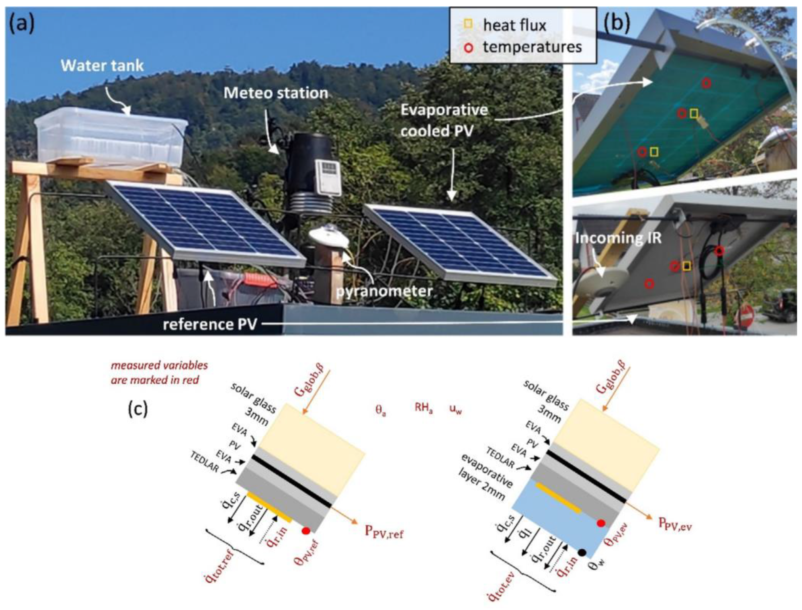
- Žižak, T.; Domjan, S.; Medved, S.; Arkar, C. Efficiency and sustainability assessment of evaporative cooling of photovoltaics. Energy 2022, 254, 124260. [Google Scholar] [CrossRef]
- Tariqa, R.; Sheikh, N.A.; Xamán, J.; Bassam, A. An innovative air saturator for humidification-dehumidification desalination application. Appl. Energy 2018, 228, 789–807. [Google Scholar] [CrossRef]
- Kim, M.H.; Park, J.S.; Jeong, J.W. Energy saving potential of liquid desiccant in evaporative-cooling-assisted 100% outdoor air system. Energy 2013, 59, 726–736. [Google Scholar] [CrossRef]
- Elsarrag, E.; Igobo, O.N.; Alhorr, Y.; Davies, P.A. Solar pond powered liquid desiccant evaporative cooling. Renew. Sustain. Energy Rev. 2016, 58, 124–140. [Google Scholar] [CrossRef]
- Hussain, S.; Kalendar, A.; Rafique, M.Z.; Oosthuizen, P. Numerical investigations of solar-assisted hybrid desiccant evaporative cooling system for hot and humid climate. Adv. Mech. Eng. 2020, 12, 1687814020934999. [Google Scholar] [CrossRef]
- Ditta, A.; Tabish, A.N.; Mujtaba, M.; Amjad, M.; Yusuf, A.A.; Chaudhary, G.Q.; Razzaq, L.; Abdelrahman, A.; Kalam, M. Experimental investigation of a hybrid configuration of solar thermal collectors and desiccant indirect evaporative cooling system. Front. Energy Res. 2022, 10, 979942. [Google Scholar] [CrossRef]
- Ghosh, A.; Bhattacharya, J. A solar regenerated liquid desiccant evaporative cooling system for office building application in hot and humid climate. Therm. Sci. Eng. Prog. 2021, 22, 100804. [Google Scholar] [CrossRef]
- Preislera, A.; Brychta, M. High potential of full year operation with solar driven desiccant evaporative cooling systems. Energy Procedia 2012, 30, 668–675. [Google Scholar] [CrossRef]
- Kabeel, A.E.; Abdelgaieda, M.; Feddaoui, M.B. Hybrid system of an indirect evaporative air cooler and HDH desalination system assisted by solar energy for remote areas. Desalination 2018, 439, 162–167. [Google Scholar] [CrossRef]
- Maerefat, M.; Haghighi, A. Natural cooling of stand-alone houses using solar chimney and evaporative cooling cavity. Renew. Energy 2010, 35, 2040–2052. [Google Scholar] [CrossRef]
- Miyazaki, T.; Akisawa, A.; Nikai, I. The cooling performance of a building integrated evaporative cooling system driven by solar energy. Energy Build. 2011, 43, 2211–2218. [Google Scholar] [CrossRef]
- Lai, L.; Wang, X.; Kefayati, G.; Hu, E. Analysis of a novel solid desiccant evaporative cooling system integrated with a humidification-dehumidification desalination unit. Desalination 2023, 550, 116394. [Google Scholar] [CrossRef]
- Shbailat, S.J.; Nima, M.A. Possible energy saving of evaporative passive cooling using a solar chimney of metal foam porous absorber. Energy Convers. Manag. X 2021, 12, 100118. [Google Scholar] [CrossRef]
- Kousar, R.; Ali, M.; Sheikh, N.A.; Gilani, S.I.H.; Khushnood, S. Holistic integration of multi-stage dew point counter flow indirect evaporative cooler with the solar-assisted desiccant cooling system: A techno-economic evaluation. Energy Sustain. Dev. 2021, 63, 163–174. [Google Scholar] [CrossRef]
- Rahman, M.S.; MacPherson, S.; Lefsrud, M. Experimental investigation of a novel evaporative cooling pad made of cement-free porous concrete. Build. Environ. 2023, 228, 109867. [Google Scholar] [CrossRef]
- Lv, J.; Huang, J.H.; Xu, H.D.; Xu, T.F.Y. Research on performance evaluation index of dew point evaporative cooler. Int. J. Refrig. 2021, 42, 126–133. [Google Scholar]
- Chen, Q.; Ja, M.K.; Burhan, M.; Akhtar, F.H.; Shahzad, M.W.; Ybyraiymkul, D.; Ng, K.C. A hybrid indirect evaporative cooling-mechanical vapor compression process for energy-efficient air conditioning. Energy Convers. Manag. 2021, 248, 114798. [Google Scholar] [CrossRef]
- Zhou, Y.Y.; Yan, Z.; Dai, Q.; Yu, Y. Experimental study on the performance of a novel hybrid indirect evaporative cooling/thermoelectric cooling system. Build. Environ. 2022, 207, 108539. [Google Scholar] [CrossRef]


| Study | Year | Approach | Major Feature |
|---|---|---|---|
| [63] | 2002 | CFD | A mathematical model, including the governing equations of liquid film and air phases as well as the interface conditions, was developed. |
| [64] | 2015 | Experiment | The efficiency of the internal two-stage evaporative cooler was higher than that of direct evaporative cooler, but it cannot be raised over 100%. |
| [65] | 2006 | CFD | The liquid film falling inside a vertical insulated tube in turbulent gas stream was studied. |
| [66] | 2011 | Experiment | Performance of pad thickness and inlet air velocity on the change of the system’s overall pressure drops, amount of evaporated water, effectiveness, humidity variation was analyzed. |
| [67] | 2017 | ANN statistical modelling | The prediction abilities of obtained models were analyzed, and a comprehensive error analysis was conducted through statistical modelling. |
| [68] | 2009 | CFD | The heat and mass transfer between air and water film in the DEC was theoretically analyzed. |
| [69] | 2012 | Experiment | Speed of frontal air, the DB of frontal air, and the temperature of the incoming water were tested for their impact on DEC cooling efficiency. |
| [70] | 2016 | Experiment | The exergetic performance indicators of DECs with wood charcoal, shredded foam latex, and jute fiber were presented. |
| Study | Year | Type | Approach | Major Feature |
|---|---|---|---|---|
| [74] | 2015 | IEC | ε-NTU method | A sensitive analysis of heat and mass transfer process was performed on the base of the ε-NTU method to establish preferable operating conditions. |
| [75] | 2014 | DPEC | ε-NTU method | A modeling of heat and mass transfer in the DPEC was described. |
| [76] | 2015 | DPEC | ε-NTU method | A mathematical simulation of heat and mass transfer in eight different types of the DPEC was studied. |
| [77] | 2023 | IEC | ε-NTU method | The method was adopted for the application of a countercurrent evaporative heat exchanger featuring. |
| [78] | 2016 | DPEC | CFD; Experiment | A minimum parametric representation for evaluating the thermal performance of a counter-flow DPEC was determined. |
| [79] | 2016 | IEC | CFD | A computational model was developed and validated using experimental data. |
| [80] | 2017 | DPEC | CFD | A more realistic boundary condition on separating wall was obtained by simultaneous solving of momentum, energy, and mass transfer equations. |
| [81] | 2017 | DPEC | CFD | A numerical study of heat and mass transfer in counter-flow DPEC was presented using an approach proposed by previous work. |
| [82] | 2015 | IEC | Finite difference method | A modeling of an IEC with consideration of wall longitudinal heat conduction and effect of spray water temperature variation along the exchanger surface was presented. |
| [83] | 2015 | DPEC | Finite difference method | The numerical simulations of cross- and counter-flow DPEC were presented. |
| Study | Year | Type | Major Feature | Role of EC |
|---|---|---|---|---|
| [102] | 2019 | Active DEC | Performance of the exergoeconomic analysis of a solar PV-DEC was assessed. The effects of inlet air rate, humidity, and thickness of cooling pad on the system were analyzed. | Producing cold air for the indoors by using SE. |
| [103] | 2023 | Passive DEC | The impact of rectangular aluminum fins and DEC on the performance of PV module was analyzed. | Cooling PV module and increasing system efficiency. |
| [104] | 2022 | Passive DEC | The efficiency and sustainability of EC of PV mode were assessed. With sustainable EC 5.9 to 11.3 kWh/m2, more energy could be produced. | Improving PV module performance. |
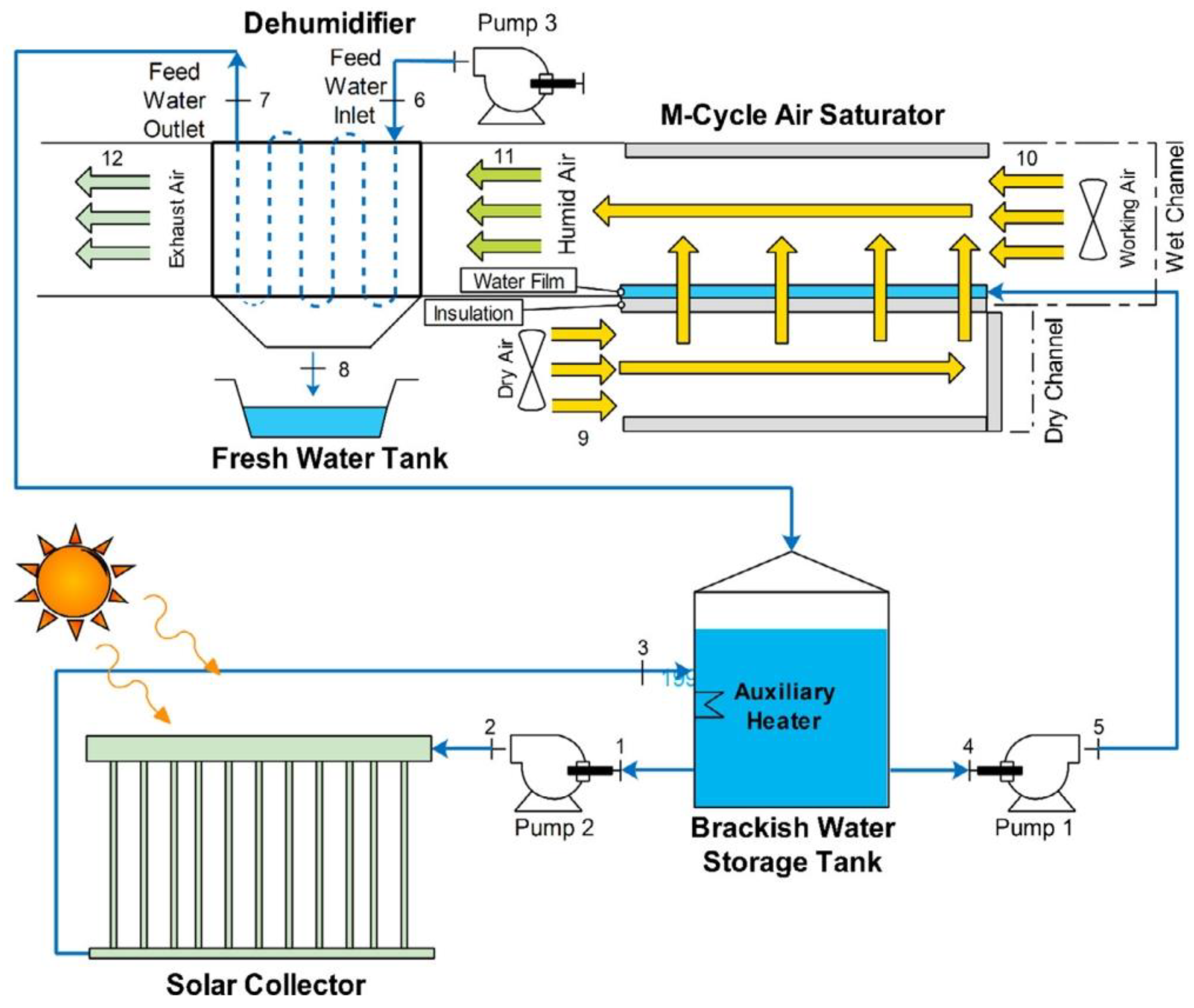
| [105] | 2018 | Counter-flow DPEC | An innovative and novel integrated M-cycle-based air saturator was proposed. The performance of exergy and efficiency was analyzed. | Decreasing the air temperature to provide conditions for desalination. |
| [106] | 2013 | I-DEC | The integration of a liquid desiccant system into an EC-assisted 100% outdoor air system was suggested. The performance of the liquid desiccant system in I-DEC operations was evaluated. | Maintaining absorber temperature of liquid desiccant system. |
| [108] | 2020 | I-DEC | Numerical investigations of the solar-assisted hybrid desiccant EC were introduced. The solar-assisted hybrid desiccant EC unit hybrid air collectors could achieve an average COP of 0.85. | Coping with cooling load, particularly sensible load. |
| [109] | 2022 | Counter-flow IEC | The hybrid configuration of solar thermal collectors was analyzed for efficiency of solar collectors and solar fraction. | Manufacturing CC. |
| [110] | 2021 | Counter-flow DPEC | The thermal COP of the system for diurnal operation in the most humid month of a calendar year varied between 0.40 and 0.96. | Preventing overheating of conditioned space. |
| [111] | 2012 | Active DEC | The performance of the solar-driven DEC system was evaluated. The primary energy-saving potential was analyzed. | Exhaust air can dry sorption rotor and wheel while providing cooling air. |
| [112] | 2018 | Counter-flow IEC | An experimental investigation on a hybrid system of IEC, HDH, and SE was proposed. The performance of this system was evaluated. | Offering the freshwater for the HDH desalination subsystem. |
| [113] | 2010 | Passive DEC | A great performance was achieved using DEC. The effects of geometric parameters on the system performance were discussed. | Reducing ambient warm air temperature and increasing indoor humidity. |
| [114] | 2011 | Counter-flow DPEC | An SC-driven DPEC system for buildings was proposed. The effects of the channel width of the evaporative cooler were synthetically discussed. | Effectively reducing the cooling load of main AC in buildings. |
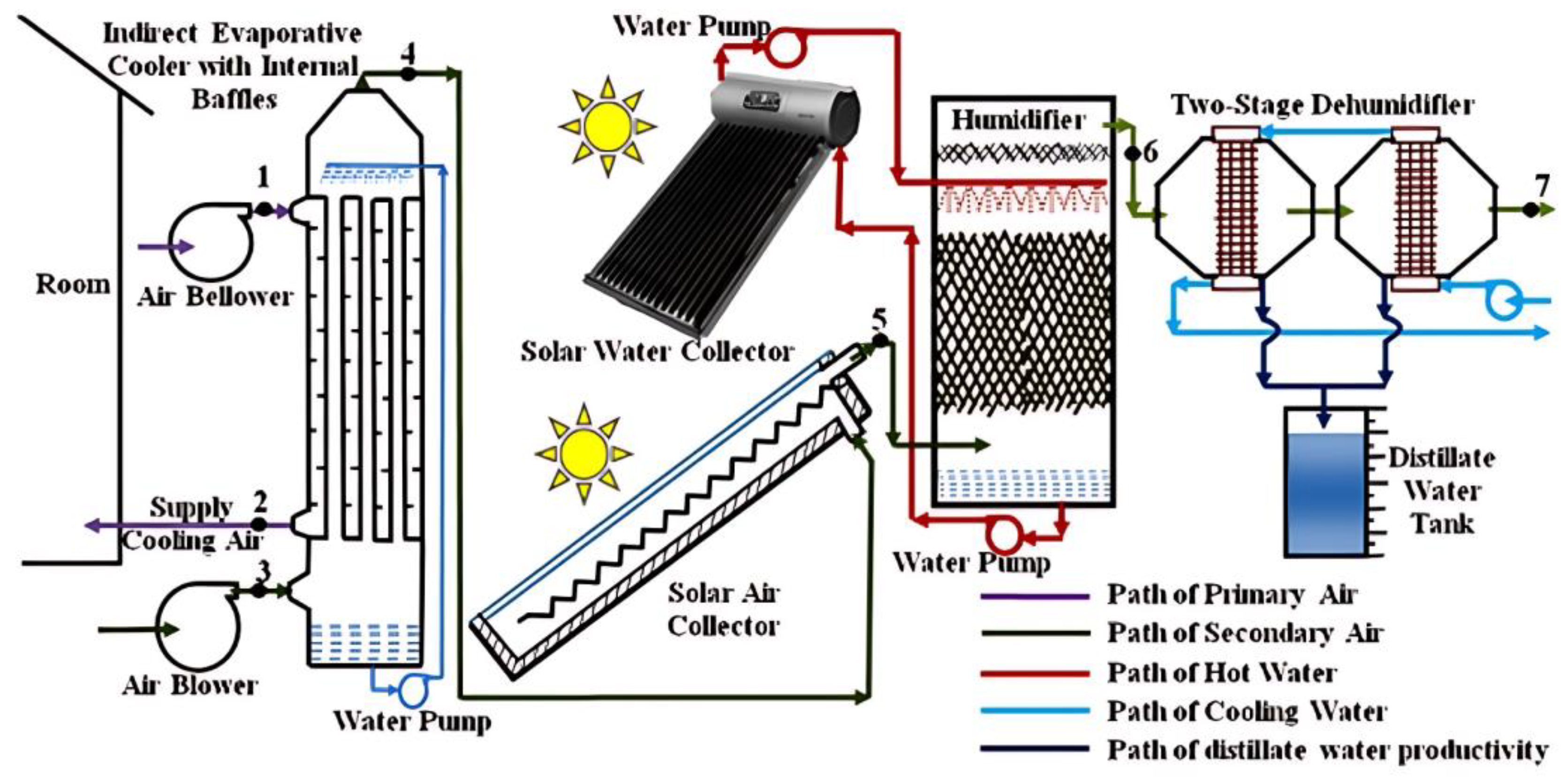
| [115] | 2023 | Counter-flow DPEC | A novel solid desiccant DPEC system integrated with SE and HDH was proposed. Performance of the system was numerically evaluated. | The air can be dried by the solar desiccant wheel and producing cold indoor air. |
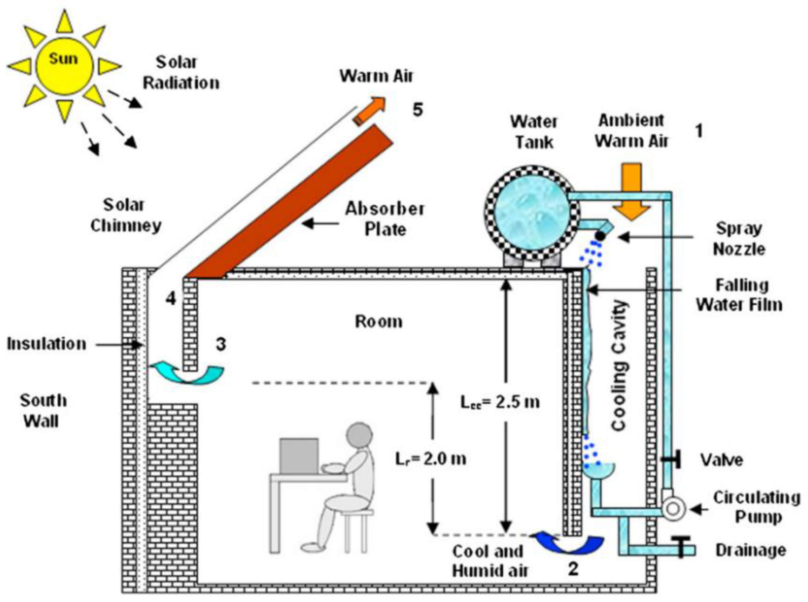
| [116] | 2021 | Passive DEC | A system combining SC and EC was proposed. Increasing the thermal efficiency of SC led to improving the natural cooling. | Increasing the relative humidity in the house. |
| [117] | 2021 | Active DEC | A performance of the solar-desiccant-assisted EC system was analyzed. The system had the potential to save up to 62.9% energy cost compared to the conventional. | Regulating air quality and providing a good environment. |
Disclaimer/Publisher’s Note: The statements, opinions and data contained in all publications are solely those of the individual author(s) and contributor(s) and not of MDPI and/or the editor(s). MDPI and/or the editor(s) disclaim responsibility for any injury to people or property resulting from any ideas, methods, instructions or products referred to in the content. |
© 2023 by the authors. Licensee MDPI, Basel, Switzerland. This article is an open access article distributed under the terms and conditions of the Creative Commons Attribution (CC BY) license (https://creativecommons.org/licenses/by/4.0/).
Share and Cite
Xue, T.; Wan, Y.; Huang, Z.; Chen, P.; Lin, J.; Chen, W.; Liu, H. A Comprehensive Review of the Applications of Hybrid Evaporative Cooling and Solar Energy Source Systems. Sustainability 2023, 15, 16907. https://doi.org/10.3390/su152416907
Xue T, Wan Y, Huang Z, Chen P, Lin J, Chen W, Liu H. A Comprehensive Review of the Applications of Hybrid Evaporative Cooling and Solar Energy Source Systems. Sustainability. 2023; 15(24):16907. https://doi.org/10.3390/su152416907
Chicago/Turabian StyleXue, Tinghui, Yangda Wan, Zhifeng Huang, Pinyi Chen, Jie Lin, Weidong Chen, and Haibo Liu. 2023. "A Comprehensive Review of the Applications of Hybrid Evaporative Cooling and Solar Energy Source Systems" Sustainability 15, no. 24: 16907. https://doi.org/10.3390/su152416907