Abstract
Owing to the special tubular structural characteristics of highway tunnels, drivers typically experience a significant change in visual luminance when entering tunnels, which seriously impacts driving safety. This paper proposes a lighting scheme based on optical fiber technology to introduce natural light into the tunnel portal section. First, an on-demand lighting scheme based on the use of daylight is designed by developing an optical fiber lighting system, lighting demand algorithm, and an on-demand lighting control scheme. Furthermore, the scheme is applied to a physical tunnel, and the safety and energy-saving potential of the scheme are analyzed based on the obtained data. The results indicate that the average luminance and luminance uniformity in the tunnel portal section appear to improve with the application of the proposed scheme; the luminance uniformity is particularly increased by 0.18. The correlative color temperature (CCT) of the environment inside the cave changes in real time with the CCT value of the phase pair outside the cave. Compared with the explicit use of electrical lighting, the lighting energy consumption during daytime can be reduced by 34.7% with the application of the proposed scheme, and the highest reduction of 79.8% can be achieved at 13:00.
1. Introduction
The number of tunnels in China has increased rapidly as tunnels are known to shorten driving mileages and promote vehicle energy conservation and emission reduction. By the end of 2021, the total mileage of highway tunnels in China, including 1599 extra-long and 6211 long tunnels, was 24,698.9 km [1]. As large-scale and multi-type tunnels are put into operation, the challenges associated with safety, comfort, and energy conservation become increasingly prominent. On the one hand, unreasonable settings of tunnel operating environments can easily cause traffic accidents, and even small traffic accidents can often lead to heavy casualties and material losses in the tunnel. On the other hand, the cost of tunnel operation equipment installation and electricity provision is extremely high. In particular, tunnel lighting equipment contributes significantly to the overall energy consumption of road tunnels. Notably, the continuous development of highway transportation infrastructure has caused a continual increase in the energy consumption of facilities in China. With the Chinese government’s dual-carbon goal of achieving a carbon peak and carbon neutrality by 2030 and 2060, respectively, the pressure on reducing carbon emissions is massive. Therefore, it is necessary to investigate measures for traffic safety and operation energy conservation under the lighting environments of highway tunnels.
Previous research in the field [2] indicates that the tunnel entrance and exit zones are accident-prone areas, accounting for 58% of total tunnel traffic accidents. Among these areas, the entrance zone represents the key section of the highway tunnel lighting system design. Currently, the tunnel lighting standard of the International Commission on Illumination (CIE) [3] and the Illuminating Engineering Society of North America (IESNA) [4] and China [5] is mainly aimed at setting the luminance conditions for the entrance and transition zones, i.e., setting a higher luminance at the entrance zone first and then gradually decreasing the luminance at the entrance and transition zones to facilitate drivers to adapt to the dark environment. On the one hand, although higher luminance is provided on the tunnel entrance section with artificial lighting, with the change in the environment, the black hole effect still affects the driver on entering the tunnel, particularly when the natural light outside the tunnel is intense. On the other hand, the greater artificial lighting luminance is bound to result in high energy consumption. Therefore, developing energy-efficient lighting for the entrance section of tunnels is crucial to ensure traffic safety.
Currently, attempts to improve tunnel entrance lighting can be roughly divided into two categories. One involves reducing the impact of natural light outside the tunnel [6,7]. For example, Peña-García et al. [8] stated that the luminance outside the tunnel could be reduced by the forestation of portal surroundings, and the lighting demands in the threshold zone resulting from the choice of each species could be quantified based on luminance measurements. He et al. [9,10] studied a driver’s driving behavior at the tunnel threshold zones, along with the driver’s eye movement parameters, such as the fixation point and pupil diameter, and revealed that the highly diffuse reflection coating of the sidewall at the tunnel threshold zone could facilitate light–dark adaptation for the driver. Qin et al. [11,12] estimated the actual luminance demand based on real-time changes in the luminance, traffic volume, and speed outside the tunnel, and proposed energy-saving lighting control technology “vehicle in, light brightens; vehicle out, light darkens”. This can be primarily realized by reducing the luminance outside the tunnel, improving the luminance inside the tunnel, or regulating the luminance at the tunnel entrance in real time.
The other strategy involves using natural light or allowing natural light to enter the tunnel portal section to improve the lighting environment [13]. For example, Gil-Martín et al. [14] proposed a theoretical scheme for the lighting tunnel threshold zone by introducing natural light from outside the tunnel into the tunnel portal section using light pipes. In this scheme, sunlight was first collected using a collector installed on the ground shoulder; following this, the collected sunlight was projected onto a vault and finally distributed across the road surface through vault reflection to achieve tunnel threshold zone lighting. Yu et al. [15] developed a solar optical reflection lighting system to be installed at the tunnel portal. This system could collect natural light through a Fresnel lens and dual axis sensor-date-time combined solar tracker; following this, it could project the collected sunlight onto the tunnel portal through a parabolic reflector to achieve uniform lighting in the tunnel threshold zone. Qin et al. [16] discussed the structural composition, materials, and characteristics of Daylighting System Using Fiber Optics (DSFO), and they designed a set of optical fiber lighting systems to be installed at the tunnel entrance. With the installation of such optical fiber lighting systems at the entrance section of the Huashuyan Tunnel, it was observed that the transmission loss of the optical fiber lighting system was 12.9%, and thus, it could provide enhanced lighting over a 30 m area of the tunnel entrance. Feng [17] analyzed the technical characteristics of optical fiber lighting components, such as optical fibers and automatic concentrators used at the threshold zone and exit of highway tunnels. They found that it was difficult to meet the luminance requirements for the tunnel portal in the Jihuang Expressway Tunnel using only optical fiber lighting; therefore, they proposed an energy-efficient lighting system by combining optical fibers with electrical lighting to meet the lighting requirements for the tunnel portal. The improvements detailed above has a certain effect in ensuring traffic safety at the tunnel portal section and in reducing lighting energy consumption. In particular, the system does not need to provide additional electrical energy during the operating period and adapts to the natural light outside the tunnel.
However, by comparing the above studies, the following challenges still appear to hinder the applications of optical fiber lighting systems in tunnel portal sections:
- (1)
- It is often difficult to satisfy the lighting needs of tunnel portal sections at different times explicitly based on optical fiber lighting. Thus, ways to compensate for electrical lighting must be proposed.
- (2)
- Guaranteed visual [18] or driving safety with the combination of natural lighting and electrical lighting must be ensured.
- (3)
- The energy-saving effect after the compensation of electrical lighting must be investigated.
In view of this, this paper innovatively proposes an on-demand lighting control technology for tunnels by utilizing daylight. The luminance requirements for the tunnel are determined using a real-time luminance feedback system based on automatically monitored luminance and traffic data collected from outside the tunnel. This system achieves intelligent on-demand lighting control that maximizes the use of daylight.
2. Principle of the On-Demand Tunnel Lighting System Based on the Use of Daylight
2.1. Design of Daylighting System Using Fiber Optics (DSFO)
The technical principle underlying this system is that sunlight is transmitted to the lighting area in a tunnel with low light attenuation via the total reflection of sunlight through a light guide fiber, and following this, the designated lighting area is illuminated by the light through the exit system.
The daylighting system employing fiber optics includes a lens combination for collecting sunlight, solar tracking system, light-carrying fiber, and a diffuser of sunlight. Among these components, the lens combination used for collecting sunlight includes a free-form surface lighting lens group designed by a ray tracing method. Furthermore, the tracking accuracy of the solar tracking system is primarily guaranteed by the optical fiber transmission technology. The solar tracking system tracks and collects sunlight according to the change in the sun’s azimuth angle. The light-carrying fiber cable is based on a six-core cabling method, and the heat sink structure is made of aluminum, which has a high thermal conductivity. The light-carrying fiber cable adopts a high-purity quartz fiber. The sunlight output is transmitted according to the three-in-one cabling method. The sunlight diffuser adopts exit taillights that provide a rectangular light distribution of tunnel lighting to ensure that the tunnel lighting conforms to the rectangular light distribution. The components of the DSFO are illustrated in Figure 1.
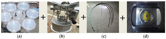
Figure 1.
Components of the DSFO. (a) Lens combination for collecting sunlight. (b) Solar tracking system. (c) Three-in-one transmission fiber optic cable. (d) Sunlight diffuser.
2.2. Design of the On-demand Lighting System
Typically, tunnel on-demand lighting refers to accurate estimations of the demand for luminance in the tunnel based on the actual traffic flow in the highway tunnel and change in luminance outside the tunnel, followed by dynamic dimming control. Notably, the output luminance of the DSFO changes with a change in the sunlight intensity, and it is affected by the efficiency of the luminous lighting system. Therefore, to achieve luminance uniformity in different sections of the tunnel to satisfy the specification requirements, the DSFO must be designed for electrical lighting compensation. By comparing the luminance of different sections, the mode and power of electrical lighting required in these different sections can be determined. A schematic demonstrating the underlying principles is illustrating in Figure 2 and Figure 3.
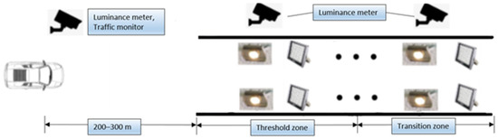
Figure 2.
Tunnel on-demand lighting scheme based on the use of sunlight.
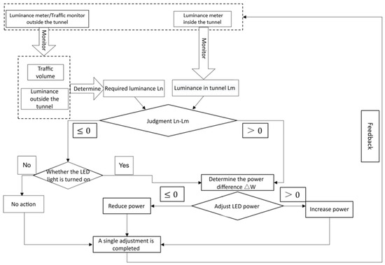
Figure 3.
Tunnel on-demand lighting control schematic.
In Figure 2, the luminance meter and traffic monitor outside the tunnel are installed 200–300 m away from the tunnel portal, which is related to the design speed of the tunnel. In-cavity luminance meters are installed in the tunnel cavity and in the threshold and transition zones to test the luminance at the road surface. According to the real-time measured luminance and traffic volume data outside the tunnel, the luminance requirements of the tunnel are determined, and the luminance meter installed inside the tunnel provides feedback on whether or not the internal luminance meets the requirements.
Based on the luminance requirements of the tunnel zones, the control system adjusts the output power of the electrical lighting system to achieve the required overall luminance. This control principle is illustrated in Figure 3.
To ensure uniform illumination and that the change in luminance meets the needs of visual adaptability, the tunnel reinforced lighting design based on solar lighting adopts a sunlight diffuser and electrical lighting fixtures (refer to Figure 4). As illustrated in Figure 4, and represent the layout spacing of the diffuser and electrical lighting fixtures in different sections, respectively.
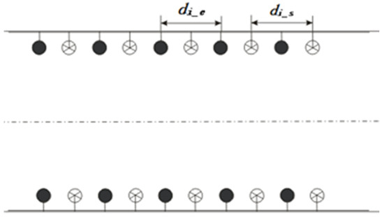
Figure 4.
Arrangement of light emitting devices.
2.3. Lighting Demand Algorithm
China’s Guidelines for Design of Lighting of Highway Tunnels [5] indicate that tunnel lighting is generally divided into five sections according to the driving direction: threshold zones (divided into threshold zones I and II according to the situation), transition zone I, transition zone II, interior zone, and exit zone. Because the luminance requirements of the tunnel threshold and transition zones are directly related to the luminance and traffic volume outside the tunnel, the demand for lighting, , can be determined based on Equation (1).
When the measured luminance in different sections of the tunnel is equal to , the variables , , , and represent the measured luminance of threshold zones 1 and 2 and transition zones 1 and 2, respectively. The required luminance difference between different sections can be represented as
Note that Equation (2) is based on the idea that the measured luminance inside the tunnel is affected by daylight and the electrical lighting system. When estimating the luminance requirement, the required increased luminance, , can be obtained by increasing the electrical lighting power in different sections. Furthermore, the increased power of the lamps, , in different sections can be expressed by Equation (3).
where , , , and represent the power that must be increased for a single luminaire in different lighting sections; is the luminance/illuminance conversion factor, usually 15 lx/(cd/m2); and denotes the road width of the corresponding lighting segment. The width of the two-lane pavement is 10.4 m in combination with the roadside and maintenance lane; , , , and denote the lengths of the corresponding lighting segments; represents the utilization of lamps and lanterns coefficients, and for LED lighting lamps, η is usually 0.8; , , , and indicate the luminous efficiency of the lamps used in different lighting sections; is the maintenance factor of the lamps; and is the factor of the arrangement of the lamps. Moreover, is two for a symmetrical arrangement and one for staggered, midline, and central lateral single light strips; when the system adopts a symmetrical arrangement mode, then is 2.
Equations (1)–(3) represent the realization principles of the energy-saving control method for on-demand lighting of tunnels combined with solar lighting.
2.4. Design of the Control Scheme
The purpose of the on-demand tunnel lighting scheme based on the use of daylight is to completely utilize sunlight. The tunnel lighting control system adjusts the light according to the luminance outside the tunnel, the traffic flow, and the luminance inside the tunnel. If the luminance inside the tunnel does not meet the lighting requirements, i.e., > 0, as given by Equation (2), the required electrical lighting power, , is calculated and then adjusted appropriately. This adjustment requires the electrical lighting power to be converted into a 0–5 V DC analog signal output such that the LED lamps can be adjusted appropriately. Here, analog control signals of 0 V and 5 V correspond to the maximum and minimum driving currents of the LED lamps, respectively, and the middle range is represented by an inverse linear relationship. Depending on the analog signal, the current of the LED lamp is adjusted to increase the luminance within each segment of the tunnel. By contrast, if the luminance is too high, the described mechanism proceeds in the same manner but for the opposite case.
According to this control scheme, sunlight can be utilized to the maximum possible extent, and a reduction in the energy consumption with electrical lighting can be achieved. Figure 5 illustrates the design of the control scheme of the on-demand tunnel lighting system based on the use of daylight.
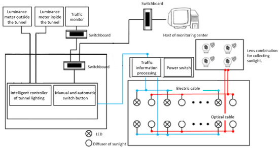
Figure 5.
Design of the control scheme of the on-demand tunnel lighting system based on the use of daylight.
3. Results
3.1. Application Design
The principles underlying the on-demand tunnel lighting scheme based on the use of daylight discussed in previous sections were tested by conducting experiments in the National Engineering Research Center for Highway Tunnels of China Merchants Chongqing Communications Research & Design Institute Co., Ltd. The test tunnel is 200 m long, 8 m wide, and 7.20 m high. The left and right sidewalks are 1.20 m wide. The sectional geometry and the actual scene in the experimental tunnel are shown in Figure 6 and Figure 7. Here, daylight was collected using the daylighting system with fiber optics outside the tunnel; the collected light was then guided into the tunnel through fiber optic cables before being projected onto the tunnel road using six sets of sunlight diffusers. Here, the six sets of sunlight diffusers were installed at the middle of the experimental tunnel to simulate the on-demand lighting control effect in the tunnel transition zone. Figure 8 and Figure 9 illustrate the daylighting system with fiber optics outside the tunnel and sunlight diffuser inside the tunnel, respectively.
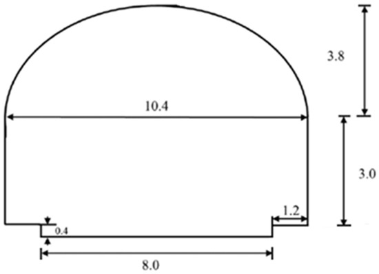
Figure 6.
The sectional geometry of the experimental tunnel.
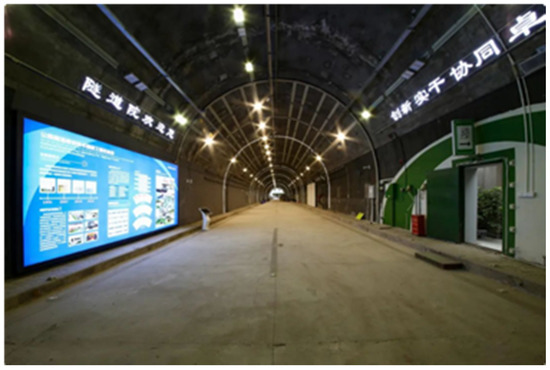
Figure 7.
The actual scene inside the tunnel.
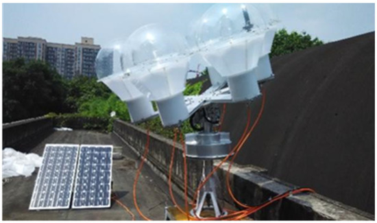
Figure 8.
DSFO located outside the experimental tunnel.
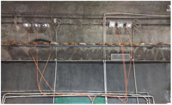
Figure 9.
Sunlight diffuser located inside the experimental tunnel.
The experimental design had to be established in the following manner to ensure that the tunnel functioned as required:
- The tunnel was equipped with a luminance meter and a simulated traffic flow detector outside the tunnel, which could transmit the collected data to the controller terminal. The detection area inside the tunnel was equipped with a luminance meter, which collected real-time luminance data from inside the tunnel and fed back the data to the control system to realize closed-loop control of on-demand lighting.
- A sunlight diffuser and LED lamps were installed to ensure that the emitted light was irradiated to the test area at the same angle, as this further ensured that the luminance recorded in the test area was the combined effect of the two light sources.
- The dimming range of the LED lamps was 0–100%. Here, dimming control automatically operated according to the luminance data recorded inside and outside the tunnel and the simulation data of the traffic volume so that the luminance in the test area could meet the design requirements and achieve the required safety and energy-saving levels.
- The system was designed with an emergency lighting function. In case of an emergency, this system would support 100% one-key operation of LED lights in the tunnel network.
The designed experimental setup simulated appropriate traffic volumes and different weather conditions. An intelligent controller moderated LED lighting according to the luminance requirements so that solar and LED lighting could collectively illuminate the tunnel, ultimately achieving the required luminance. This combined lighting was compared with LED lighting alone so that energy-saving effects could be analyzed. The specific test conditions and steps were as follows:
- The sunny conditions in the low-traffic mode and the road surface of the two-vehicle tunnel were tested.
- Test process:
- (a)
- In the presence of sunlight, the luminance on the road in the designated area was tested. The intelligent controller adjusted the LED power until the luminance under the combined lighting action reached the desired value, and the LED power was recorded at this time.
- (b)
- When the lighting surface of the external lighting system was blocked, no sunlight entered the tunnel. The LED power was adjusted via the intelligent controller until the luminance under the action of a single LED reached the desired value, and the LED power was recorded at this time.
Figure 10 illustrates the simultaneous effect of laboratory solar lighting and LED lighting dimming control.
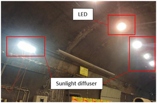
Figure 10.
Co-illumination effect of sunlight and LED illumination in the tunnel.
3.2. Data Analysis
According to the above test methods and steps, the application effects were tested from the perspectives of luminance, luminance uniformity, and color temperature improvement. The following results were obtained:
3.2.1. Lighting Effect Test
This test employed a CX-2B luminance meter to test the luminance change in a test area under different luminance values outside the tunnel within a one-day period. The meter specifically recorded the power change in the LED lighting system under the corresponding luminance changes. The test results are presented in the table below.
Figure 11 illustrates a comparison between the test luminance and design luminance of the test area and the LED power at different times. According to Figure 9 and Table 1, the measured luminance satisfies the luminance demand at any time. The average measured luminance is 10 cd/m2, whereas the average required luminance is 9.7 cd/m2, which is 0.3 cd/m2 higher. Meanwhile, the output power of the LED lights increases from 8:00, reaches a peak value of 51.8% at 10:00, and then gradually decreases. At 13:00, the output power reaches a trough value of 20.8% and then slowly rises. At 15:00, it reaches a wavelet peak of 40.8% and then slowly decreases. It can be observed that the entire power curve of the LED comprises two increasing and decreasing sections. This is different from the expected simple increase and decrease behavior. By comparing the power change of the LED with the change in the L20 value, we can observe that the L20 value increases first and then decreases, after which it reaches its peak at 13:00. Compared with the power change of the LED, it is determined that its relationship with optical fiber is not simple linear correlation.
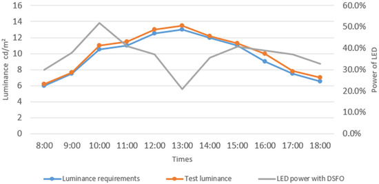
Figure 11.
Comparison of test area luminance requirement, actual luminance, and LED power.

Table 1.
Experimental tunnel luminance and LED lighting power at different times of the day.
In addition, the LED lighting system did not achieve a 100% power working state in all periods, implying that the lighting system completely utilized sunlight to illuminate the test area, thereby reducing lighting energy consumption and prolonging the life of lamps.
3.2.2. Lighting Quality
Because direct sunlight has a different correlative color temperature (CCT) than electrical lighting, the luminance uniformity and CCT in the lighting area for the two lighting methods result in the same average luminance level. In the experiment, a luminance meter and a photometer were utilized to test the luminance uniformity and CCT with or without sunlight from 8:00 to 18:00, and the results are illustrated in Figure 12 and Figure 13.
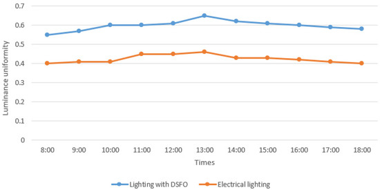
Figure 12.
Comparison of luminance uniformity with and without sunlight.
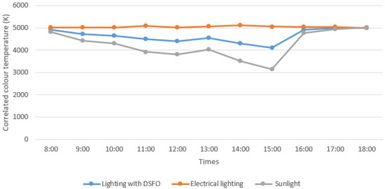
Figure 13.
Comparison of color temperature with and without sunlight.
Evidently, Figure 12 indicates that, at any point, the luminance uniformity of the measurement area with the use of optical fiber lighting is better than that in the absence of optical fiber lighting. The average luminance uniformity of the measurement area when optical fiber lighting was used was 0.60, and the average luminance uniformity of the measurement area when optical fiber lighting was not used was 0.42, which is 0.18 higher. The time when the luminance uniformity was the highest was 13:00. Thus, the change trend followed by the luminance uniformity is consistent with the change trend followed by L20(S) outside the tunnel when optical fiber lighting is used.
This also indicates that when optical fiber lighting is used, the pavement luminance uniformity is higher, and with an increase in the amount of natural light outside the tunnel, the pavement luminance uniformity is also expected to improve. Furthermore, in the presence of sunlight, the luminance uniformity in the lighting area is better than that without sunlight, implying that the lighting in the presence of sunlight is of better quality.
Figure 13 indicates that, at any time, the CCT of the measurement area with the use of optical fiber lighting is higher than the CCT outside the tunnel; this value is lower than that obtained when optical fiber lighting is not used in the tunnel, and the CCT of the measurement area changes with the change in the CCT outside the tunnel when optical fiber lighting is used. The average CCT of the measurement area is 4640 K when optical fiber lighting is used, 5038 K when optical fiber lighting is not used, and 4242 K outside the tunnel.
This also indicates that when optical fiber lighting is used, the CCT of the environment inside the tunnel changes with the change in the CCT of the environment outside the tunnel, and the value is between the CCT outside the tunnel and the CCT of the electrical lighting inside the tunnel; this may aid in easing the brightness transition between the inside and outside of the tunnel and is thus conducive to ensuring driving safety.
3.2.3. Energy Saving
The on-demand tunnel lighting scheme based on the use of daylight aims to maximize the use of sunlight to realize energy saving with electrical lighting. The energy-saving effect is particularly evident in the period when the sunlight intensity is high, for example, on sunny days, and when the demand for luminance enhancement of the threshold zones is high. In the experiment, we tested the power comparison of electrical lighting with the same on-demand lighting control and same luminance level with or without sunlight under the same weather conditions.
Table 2 presents a power comparison of the LED lighting system with or without sunlight recorded on a typical sunny day in summer.
Table 2.
Power comparison of LED lighting system in typical sunny days in summer with or without sunlight.
As can be observed from Table 2 and Figure 14, the average value of lighting power when only using the electrical lighting system is as high as 74.2%, whereas the average value of system power with DSFO is only 36.8%, and the average value is reduced by 34.7%. From 8:00 to 18:00, with the increase in sunlight intensity, the lighting power with electrical lighting increases, whereas the corresponding power of the lighting system with DSFO decreases; at this time, the energy-saving effect of the system is better. Particularly, at 13:00, the maximum difference between the lighting power of the two systems is up to 79.87%. This implies that on a sunny day with intense sunlight and the same average luminance level, the power of a single LED lamp with sunlight is significantly lower than that of a single lamp without sunlight, particularly at noon, in the presence of sunlight.
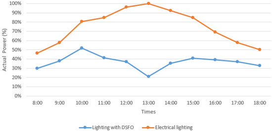
Figure 14.
Energy-saving comparison of on-demand lighting control system for tunnels based on sunlight illumination.
When the sunlight is less intense, the energy-saving rate is reduced, but the energy consumption requirement of enhanced lighting itself is not high at this time. The specific energy-saving effect is related to the scale of the solar lighting system used in the actual system. The power comparison results of the two systems at different periods summarized in Table 2 and Figure 12 imply that the higher the sunlight intensity, the greater the energy-saving effect achieved. Furthermore, with the increase in the efficiency of the DSFO technology, the efficiency of its application in highway tunnel lighting will be further improved.
4. Conclusions
In this study, we demonstrated that on-demand lighting control systems based on the use of daylight may be an alternative energy-saving technology to sufficiently illuminate tunnels. We described the principles underlying the technology, proposed a method and intelligent control scheme, and tested the system based on an experimental tunnel application; consequently, the following conclusions were drawn:
- With the application of the on-demand tunnel lighting system based on the use of daylight, the average luminance increases by 0.3 cd/m2, and the luminance uniformity in the lighting area increases by 0.18 compared with electrical lighting. The CCT changes with the change in sunlight; therefore, reducing large changes in portal luminance by reducing differences in CCT is advantageous.
- Compared with the electrical lighting system, the lighting power of the on-demand tunnel lighting system based on the use of daylight is only 36.8%, and the average value is reduced by 34.7%. The utilization of daylight can reach 79.8% based on the demand for lighting in threshold zones on sunny days in summer.
- Future research will focus on three aspects: coupling efficiency and transmission rate of DSFO, adaptability to daylight environments in a real tunnel, and visual and non-visual effects of the lighting environment for the tunnel-on-demand lighting energy-saving technology based on solar lighting.
Author Contributions
Conceptualization, L.S.; Methodology, L.S.; Software, L.S.; Data curation, X.W., Z.H. and C.Z.; Writing–original draft, X.W.; Writing–review & editing, S.H. and P.B.; Supervision, Y.T. All authors have read and agreed to the published version of the manuscript.
Funding
This research was supported by the Project of the National Natural Science Foundation of China (Grant no. 52108362) and funded by the Key Projects for Technological Innovation and Application Development in Chongqing (Grant no. CSTB2022TIAD-KPX0116, CSTB2022TIAD-KPX0117).
Institutional Review Board Statement
Not applicable.
Informed Consent Statement
Not applicable.
Conflicts of Interest
The authors declare no conflict of interest.
References
- Ministry of Transport of China. 2021 Statistical Bulletin on the Development of the Transportation Industry. 2022. Available online: https://www.chinahighway.com/article/65393930.html (accessed on 16 September 2022).
- Lai, J.; Zhang, P.; Zhou, H.; Cheng, F.; Qin, H. Study of rules of traffic safety in expressway tunnels. Tunn. Constr. 2017, 37, 6. [Google Scholar]
- International Commission on Illumination. CIE 88–2004 Guide for the Lighting of Road Tunnels and Underpasses; Commission Internationale de l’Éclairage: Vienna, Austria, 2004. [Google Scholar]
- The Illuminating Engineering Society of North America. ANSI/IES RP-22-11 Tunnel Lighting; The Illuminating Engineering Society of North America: New York, NY, USA, 2011. [Google Scholar]
- Ministry of Transport of the People’s Republic of China. JTG/T D70/2-01-2014 Guidelines for Design of Lighting of Highway Tunnels; Ministry of Transport of the People’s Republic of China: Beijing, China, 2014.
- Cantisani, G.; Di Mascio, P.; Moretti, L. Comparative life cycle assessment of lighting systems and road pavements in an Italian twin-tube road tunnel. Sustainability 2018, 10, 4165. [Google Scholar] [CrossRef]
- Dong, L.; Shang, X.; Zhao, Y.; Qin, L.; Xu, W. The impact of LED light color on the dark adaptation of human vision in tunnel entrances. IEEE Photonics J. 2018, 10, 1–11. [Google Scholar] [CrossRef]
- Peña-García, A.; López, J.C.; Grindlay, A.L. Decrease of energy demands of lighting installations in road tunnels based in the forestation of portal surroundings with climbing plants. Tunn. Undergr. Space Technol. 2015, 46, 111–115. [Google Scholar] [CrossRef]
- He, S.Y.; Tähkämö, L.; Maksimainen, M.; Liang, B.; Pan, G.B.; Halonen, L. Effects of transient adaptation on drivers’ visual performance in road tunnel lighting. Tunn. Undergr. Space Technol. 2017, 70, 42–54. [Google Scholar] [CrossRef]
- He, S.; Ren, Y.; Liu, H.; Liang, B.; Du, G. A novel tunnel lighting method aided by highly diffuse reflective materials on the sidewall: Theory and practice. Tunn. Undergr. Space Technol. 2022, 122, 104336. [Google Scholar] [CrossRef]
- Qin, L.; Dong, L.; Xu, W.; Zhang, L.; Yan, Q.; Chen, X. A ‘Vehicle in, Light Brightens; Vehicle out, Light Darkens’ energy-saving control system of highway tunnel lighting. Tunn. Undergr. Space Technol. 2017, 66, 147–156. [Google Scholar] [CrossRef]
- Qin, L.; Dong, L.L.; Xu, W.H.; Zhang, L.D.; Leon, A.S. An intelligent luminance control method for tunnel lighting based on traffic volume. Sustainability 2017, 9, 2208. [Google Scholar] [CrossRef]
- Yao, J.; Ning, D. Design of sunlight direct enhanced lighting system for highway tunnels. Appl. Opt. 2014, 35, 230–236. [Google Scholar]
- Peña-García, A.; Cabeza-Lainez, J. Daylighting of road tunnels through external ground-based light-pipes and complex reflective geometry. Tunn. Undergr. Space Technol. 2023, 131, 1–9. [Google Scholar] [CrossRef]
- Yu, S.; Shi, L.; Zhang, L.; Liu, Z.; Tu, Y. A Solar Optical Reflection Lighting System for Threshold Zone of Short Tunnels: Theory and Practice. Tunn. Undergr. Space Technol. 2023, 131, 104839. [Google Scholar] [CrossRef]
- Qin, X.; Zhang, X.; Qi, S.; Han, H. Design of solar optical fiber lighting system for enhanced lighting in highway tunnel threshold zone: A case study of Huashuyan tunnel in China. Int. J. Photoenergy 2015, 2015, 1–10. [Google Scholar] [CrossRef]
- Feng, S. Research on application technology of optical fiber lighting in Yutai Tunnel of Jihuang Expressway. Chin. J. Undergr. Space Eng. 2012, 8, 5. [Google Scholar]
- Sreelakshmi, K.; Ramamurthy, K. Review on fibre-optic-based daylight enhancement systems in buildings. Renew. Sustain. Energy Rev. 2022, 163, 112514. [Google Scholar] [CrossRef]


Disclaimer/Publisher’s Note: The statements, opinions and data contained in all publications are solely those of the individual author(s) and contributor(s) and not of MDPI and/or the editor(s). MDPI and/or the editor(s) disclaim responsibility for any injury to people or property resulting from any ideas, methods, instructions or products referred to in the content. |
© 2023 by the authors. Licensee MDPI, Basel, Switzerland. This article is an open access article distributed under the terms and conditions of the Creative Commons Attribution (CC BY) license (https://creativecommons.org/licenses/by/4.0/).