Abstract
Direct drive wave energy converters (DDWECs) have gradually become the mainstream of wave energy converters (WECs). In order to make better use of wave energy, energy storage devices and other renewable energy sources are often used to suppress power fluctuation in DDWECs. However, the addition of other energy sources will increase the complexity of the converter system and the number of power switches. Considering the flexibility of nine-switch converters (NSCs), this paper proposes a novel nine-switch grid-connected/off-grid multiport hybrid wave energy system (HWES). First, the system structure and modulation principle are described. Then, a model for a generator, a grid and energy storage are built, including a control strategy of each part. Finally, a simulation for the grid-connected/off-grid application and an experiment on the off-grid HWES are carried out. The results show that the multiport wave energy system can achieve the objective of stable and reliable power transmission by reducing power devices.
1. Introduction
With the increase in energy demand, it is a continuous process of human society to find renewable energy sources to replace fossil fuels. The ocean occupies 71% of the Earth’s surface and contains abundant renewable energy. Wave energy, as a kind of marine energy with wide distribution, greater energy density and high accuracy in energy prediction, has come into people’s sight and has been widely studied [1]. Compared with wind and solar energy, wave energy can generate energy in 90% of the time [2]. It is estimated that the total annual wave energy in the world is 20,000 to 80,000 TWh, which is 1–4 times the global energy consumption [3]. Similar to wind energy utilization, wave energy usually requires energy capture devices to convert mechanical energy into electrical energy. It is reported that thousands of different wave energy converters (WECs) and principles have been proposed and patented [4].
Among numerous WECs, direct drive wave energy converters (DDWECs) are a promising solution due to their simple mechanical structure, low maintenance cost and high energy conversion rate [5,6]. A permanent magnet linear generator (PMLG) is the core device of DDWECs, and it eliminates the intermediate mechanical interfaces and improves the conversion rate of wave energy. A PMLG connected to a dc bus through a three-phase six-switch rectifier is the classic and most commonly used structure at present [7,8,9]. Although DDWECs are an attractive option for wave energy capture, the electrical energy output from the PMLG is of variable frequency and amplitude, which will bring severe challenges to wave energy utilization and grid connection [10].
Similar to the power compensation methods of other renewable energy sources, an energy storage system (ESS) can also be applied to hybrid wave energy systems (HWESs). In [11], supercapacitors are used in a grid-connected wave energy conversion system to stabilize dc bus voltage and provide stable power to the power grid. However, the disadvantage of supercapacitors is that they only provide short-term energy storage and cannot support the long-term operation of the system. In view of the defects of single energy storage, some scholars have proposed applying a hybrid energy storage system (HESS) to solve the problem. A HESS usually consists of energy-type and power-type components that smooth out low- and high-frequency power fluctuations, respectively. So far, a variety of HESS combinations have been developed, such as supercapacitors and batteries [12,13,14]; supercapacitors and undersea energy storage [15]; and superconducting magnetic energy storage and batteries [16]. Due to the abundance of offshore renewable energy, multi-energy complementary solutions such as wind–wave complementary configurations [17,18] have also been proposed to mitigate power fluctuations. These hybrid energy-matching schemes have advanced the use of wave energy and created conditions for wave energy stability.
In the literature above, the common feature is that different forms of sources or loads are connected to the dc or ac bus through their own converters. There is no doubt that conventional classical converters such as six-switch rectifiers and buck-boost converters have certain advantages in bus decoupling, loss distribution, etc. However, it is generally accepted that integrated topologies customized specifically for multiport conversion are more compact in size and lower in quality. Recently, due to the characteristics of centralized topology and miniaturization, renewable energy source systems based on multiport converters have been welcomed by scholars. Among numerous multiport converter topologies, nine-switch converters (NSCs) have been applied in ac/ac and ac/dc energy systems with the flexibility of the modulation principle. In [19], an integrated photovoltaic and dynamic voltage restorer system based on NSC was proposed. In [20,21], NSC and its expandable version were applied to a wind generation system. A compact interlinking converter modular for hybrid ac/dc microgrids was proposed in [22], which involves a nine-switch topology with a compact configuration and fewer switches. In general, NSCs can be used as an alternative to back-to-back converters. While the number of switches is reduced, the voltage stress on the dc side is increased, but it is still an excellent integration scheme.
To the best of the authors’ knowledge, there is no precedent for multiport converters being applied to HWESs. Although a multiport wave–wind system is integrated by magnetic coupling in reference [18], the converter used was still a conventional bridge structure, and its high-frequency module increased the system cost. Due to the particularity of the marine environment, the miniaturization and integration of the HWES will undoubtedly have a beneficial impact on the layout and design of the wave energy application field. Considering the advantages of NSCs in integration and their excellent performance in ac/ac and ac/dc applications, this provides a new option for HWESs. Therefore, this paper aims to replace the common dc bus structure of a conventional HWES with an NSC. Figure 1 shows a typical application scenario of an offshore multiport HWES. Of course, it is also feasible to use this device on the coast.
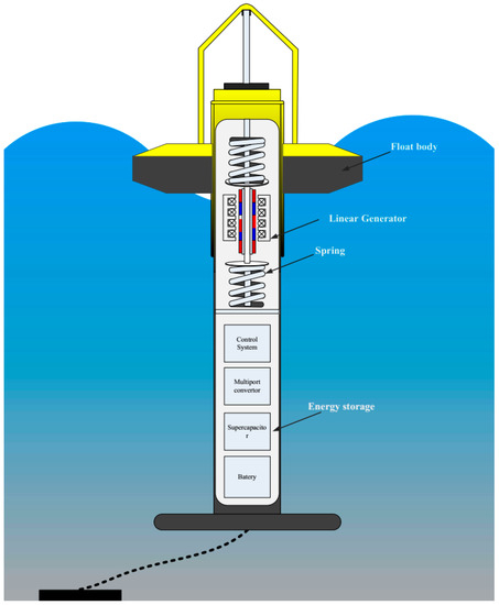
Figure 1.
Multiport hybrid wave energy system.
The paper is organized as follows. The multiport system configuration and operation principle of NSCs are described in Section 2. In Section 3, the modeling of a PMLG, energy storage, and a grid is completed. In addition, the control strategies of two types of HWESs are analyzed. The simulation results of grid-connected and off-grid HWESs on Matlab/Simulink are shown and discussed in Section 4. An experiment based on a laboratory platform verifies the off-grid HWES in Section 5. Then, several HWES structures are compared in Section 6. Finally, conclusions are drawn in Section 7.
2. System Configuration and Operation Principle
2.1. Conventional Hybrid Wave Energy System
The conventional common dc-bus-type HWES is shown in Figure 2. In the grid-connected system, the generator and grid are connected through a back-to-back converter. On the dc side of grid-connected systems, large-capacity capacitors or parallel energy storage devices are usually installed to reduce the voltage fluctuation of the bus. In the off-grid condition, in order to provide stable power to the load, energy storage is required to stabilize the dc bus voltage. A HESS composed of a battery and supercapacitor is common. Figure 2b shows a possible converter system configuration that includes a six-switch rectifier and three bidirectional dc-dc converters. The PMLG is connected to the dc bus through a rectifier. The load, supercapacitor and battery are connected to the low-voltage side of their respective converters.
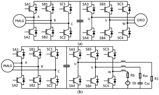
Figure 2.
Conventional topology: (a) grid-connected system; (b) off-grid system.
2.2. Multiport Hybrid Wave Energy System
The proposed multiport HWES is shown in Figure 3. An NSC is used here as the main topology to connect PMLGs and other energy devices. In the grid-connected system, all six ports of the NSC are connected to the ac source. The upper port of the NSC is connected to the PMLG, and the lower port is connected to the power grid. In the off-grid system, the upper three ports are connected to the ac source, while the lower three ports are connected to the dc source. One possible configuration proposed in this article is one where the upper port of the NSC is connected to the PMLG; the lower port U is connected to the dc load; the V is connected to the supercapacitor; and the W is connected to the battery. Only one converter and one controller are used in the multiport wave power generation system, which greatly reduces the complexity compared with the conventional structure.
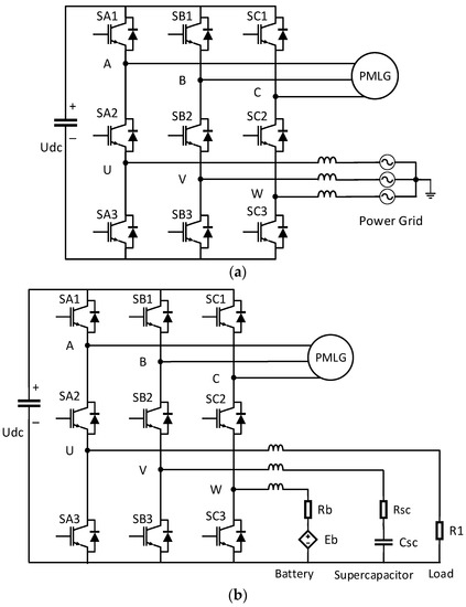
Figure 3.
Multiport topology: (a) grid-connected system; (b) off-grid system.
2.3. Modulation Principle of Nine-Switch Converter
It can be seen from Figure 3 that the NSC is composed of the upper three switches, SA1, SB1 and SC1; the middle three switches, SA2, SB2 and SC2; the lower three switches, SA3, SB3 and SC3; and a dc bus capacitor. The most critical configuration of an NSC is that the middle switches are shared by the upper and lower switches of the leg. The modulation state of the first leg, where SA1, SA2 and SA3 are located, will be analyzed as an example. In order to ensure that it is not short-circuited on the dc side, and the two output electrical potentials, and , are not floating, the first leg will not be able to generate the states of and . The switching states of the other two legs will follow the same principle. The modulation state of the A-phase leg of the NSC is shown in Table 1. It can be seen that there are only three switching states, and only two switches are on at any time.

Table 1.
Switching state and potential of the A-phase leg.
In order to implement the states in Table 1, the special SPWM modulation principle [23] is applied to the NSC in this paper. Here, in the upper and lower ports of the A-phase, the different output frequency voltages are taken as an example, which is also the mode applied throughout this paper. The modulation process is shown in Figure 4. It is worth noting that, in order to fully utilize the dc bus voltage and avoid invalid states, the same dc offset can be added to each phase of the three-phase output of the NSC. In this way, although the output phase voltage contains dc components, the dc components in the line voltage cancel each other and are still displayed as three-phase ac voltage. Equation (1) explains the conduction rule of the three switches on the A-phase leg. For the upper switch, when the modulation wave is greater than the carrier wave, it is conductive. The lower switch is on the contrary, which is to ensure . The middle switch, SA2, is passively generated by the conduction state of its upper and lower switch through XOR logic. In practical application, it is necessary to consider the addition of dead time, so the conduction rule of the middle switch with dead time added is described in Equation (1), where is the complementary signal of SA1, and is the complementary signal of SA3.
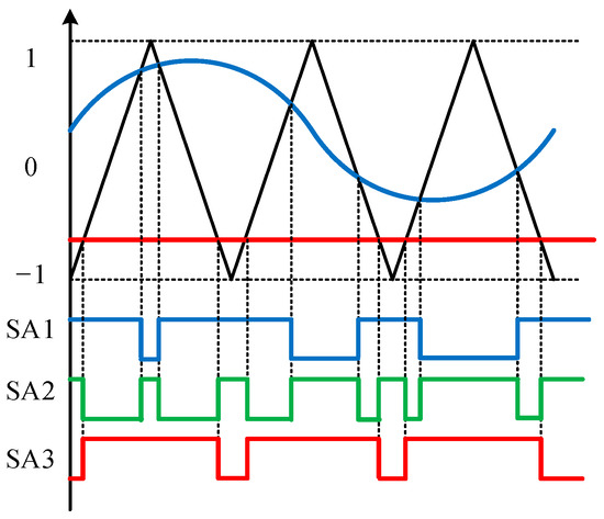
Figure 4.
A-phase modulation process of a nine-switch converter.
3. Modeling and Control Strategy
3.1. dq Model of a PMLG
The DDWEC includes a float and a PMLG device. The float is responsible for capturing the mechanical energy generated by the wave motion and driving the PMLG’s translator back and forth. The relative motion between the mover and stator of the PMLG is generated, and the induced electromotive force is generated when the magnetic field line is cut by the winding. The frontend float is within the research field of hydrodynamics, which will not be discussed here. For the convenience of control, a PMLG model in the dq coordinate system is established here.
Assuming that the three-phase windings of the stator are symmetrical, and the magnetomotive force of the permanent magnet is constant, the magnetic chain amplitude generated by the permanent magnet in each phase winding is ; then,
where is the flux linkage generated on the winding by the permanent magnet on the dq-axis, is the displacement, is the pole distance and is the electric angle of the translator movement.
Electromotive potential generated by permanent magnet flux linkage in the stator winding will be shared by an armature reaction, resistance loss and winding terminal voltage. According to Faraday’s law of electromagnetic induction and Kirchhoff’s law of voltage,
where is the electromotive force of the dq-axis; is the terminal voltage of the stator dq-axis; is the resistance of the stator dq-axis; is the current of the stator dq-axis; and is the self-inductance of the stator dq-axis.
The active power, , and reactive power, , of the generator in the dq-axis can be expressed as
According to the rule of virtual flux orientation, the active power output of the generator is only related to its q-axis current, and the reactive power output is only related to its d-axis current. The electromagnetic force, , of PMLG can be obtained from its electromagnetic power, , and motion speed, .
3.2. Power Grid Model
The same analysis method as that of a PMLG can be adopted for the power grid, but only the voltage equation needs to be considered because there is no change in the moving parts involved. The voltage equation can be expressed as
where is the electromotive force of dq-axis of the power grid; is the terminal voltage of the dq-axis; is the current of the dq-axis; and is three-phase symmetrical inductance of the power grid.
The instantaneous expression of the active and reactive power of the grid model is the same as in Equation (4). According to the grid voltage orientation rule, the active power output by the grid is only related to its d-axis current, and the reactive power output is only related to its q-axis current.
3.3. Energy Storage Model
3.3.1. Supercapacitor Model
A supercapacitor is a kind of high-power energy storage component. Compared with a battery, it is superior in charge and discharge speed and service life. In the application scenario of this paper, the focus is on the external characteristics of a supercapacitor. Therefore, the classical first-order RC model is adopted in this paper, which is relatively simple and can accurately reflect the characteristics of a supercapacitor in the charging and discharging process [24]. As shown in Figure 5a, the model consists of a capacitor, , which represents the capacity of the supercapacitor and an equivalent series of internal resistance, . The internal resistance represents energy loss and is also the cause of voltage fluctuation in the supercapacitor. The current stored energy in the supercapacitor, E, can be expressed in terms of and the terminal voltage, , as follows:
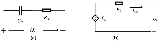
Figure 5.
HESS model. (a) First-order RC circuit model of a supercapacitor; (b) simple equivalent model of a battery.
The state of charge (SOC) of the supercapacitor can be expressed as
where and , respectively, represent the upper and lower limits of the working voltage of the supercapacitor.
3.3.2. Battery Model
A battery is a typical energy storage element. It does not frequently switch charge and discharge modes during stable operation, and its equivalent capacitance can be ignored. Therefore, the Thevenin equivalent model of a battery can be composed of an ideal controlled voltage source and a resistor in a series [25], as shown in Figure 5b. The controlled voltage source can be expressed as
where represents the no-load voltage; represents the voltage–time constant; represents the polarization voltage; represents the battery capacity; represents the actual battery capacity; represents the amplitude of the exponential zone; represents the time constant of the exponential zone; and represents the battery current.
The SOC of the battery can be expressed as
where and represent the current and initial SOC, respectively, and represents the charging and discharging efficiency of the battery.
3.4. Control Strategy
For the grid-connected system, the control strategy is composed of a generator side and a grid side. As shown in Figure 6, the zero d-axis current control strategy is applied to the PMLG. The maximum power point tracking (MPPT) is used to set the q-axis current corresponding to the active power. The reference value of iq is provided by Equation (11), where is the hydrodynamic damping coefficient of the float [7]. The d-axis current is set to zero to reduce changes in the reactive power, and the independent control of the dq-axis current is realized through feedforward decoupling.
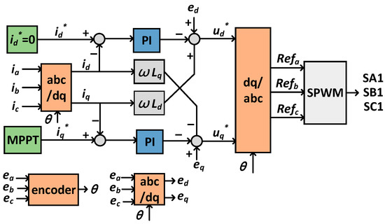
Figure 6.
Control block diagram of the PMLG.
Figure 7 shows the voltage-oriented control (VOC) of the power grid. According to the power balance, the voltage change in the dc bus is proportional to the active power absorbed by the dc bus. Therefore, the basic control strategy is as follows: the reference value of the d-axis current is determined by the voltage change in the dc bus, and the q-axis current controlling the reactive power is set as zero.
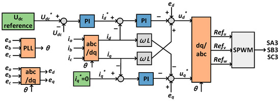
Figure 7.
Control block diagram of the power grid.
For the off-grid system, the generator side control block diagram remains unchanged. The control of the energy storage and load side is shown in Figure 8. A voltage–current double loop control is adopted for the supercapacitor and load. The supercapacitor is used to stabilize the dc bus voltage, and the control objective of the load is to stabilize its own voltage. Since the average generation power of the PMLG can be predicted, the power consumed by the load is generally kept constant. The role of the battery is to balance the difference between the average power of the two in this period of time. A power–current double loop control is adopted for the battery. The power assumed by the battery is expressed as
where is the load power, and is the average power of the PMLG. It should be noted that the gate signals of SA2, SB2 and SC2 are generated passively by Equation (1).
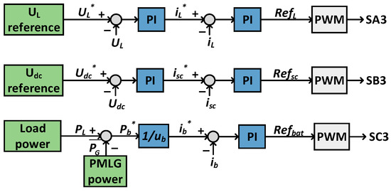
Figure 8.
Control block diagram of the battery, supercapacitor and load.
4. Simulation Analysis
The simulation is completed on the Matlab/Simulink platform. The switching frequency is set to 10 kHz, and the simulation time is set to 10 s. The simulation parameters of grid-connected and off-grid HWES are shown in Table 2.
Table 2.
Simulation parameters of multiport HWES.
Figure 9 shows the correlated waveforms of the wave input. In order to simulate the dynamic characteristics of waves conveniently, a diffraction force of 0–5 s is set as a sinewave with an amplitude of 600 N and a frequency of 5 Hz. For 5–10 s, the diffraction force is set as a sinewave with an amplitude of 1000 N and a frequency of 3 Hz. In the DDWEC, the translator of the PMLG is directly connected to the float and reciprocates with the rise and fall of the wave. The hydrodynamic model of [26] is referred to here. The velocity of the translator is shown in Figure 9b. It can be seen that, with the enhancement of the amplitude and the frequency of the diffraction force, the corresponding characteristics of the translator speed also increase.
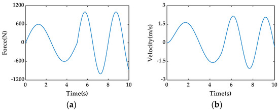
Figure 9.
Simulation of wave input: (a) diffraction force; (b) velocity of the translator.
Figure 10 shows the simulation results of the PMLG. There are two waveforms of the back-EMF in one wave cycle, which is related to the change in the moving direction of the translator. It can be seen from Figure 10a,b that the amplitude and frequency of the back-EMF and three-phase current for 0–5 s are significantly lower than those for 5–10 s, which is related to the change in the translator speed. This is also verified by the waveform of the active power, which peaks at about 750 W in the first stage and about 1300 W in the second stage. The three-phase output current and voltage are kept in phase, which shows that the reactive power is better controlled near zero.
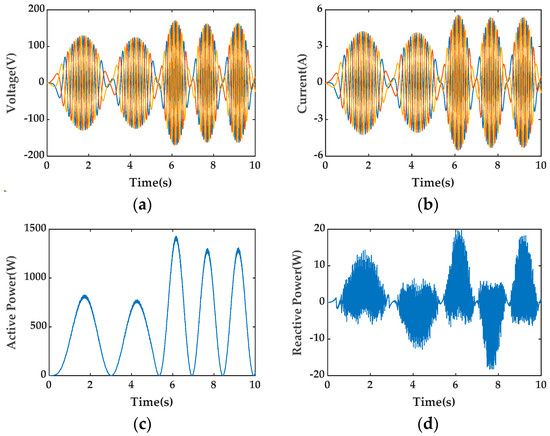
Figure 10.
Simulation of PMLG side: (a) back-EMF; (b) three-phase current; (c) active power; (d) reactive power.
Figure 11 shows the grid-side simulation waveform of the grid-connected multiport HWES. The grid voltage is stable at an amplitude of 220 V and a frequency of 50 Hz. The voltage waveform of 5–5.1 s is intercepted in Figure 11a. In order to stabilize the voltage of the dc bus, the current amplitude injected into the network side fluctuates due to the change in power on the PMLG side. If the stable injected grid current is also an indicator, energy storage can be added to the dc side, which, of course, will also increase the complexity of the system. The dc bus voltage is stable at around 1000 V, and the deviation is less than 5%. It can be seen that the voltage fluctuation in the first 5 s is less than that of the second 5 s, which is also caused by the change in the wave input. The upper half of the modulation wave corresponds to the PMLG, while the lower half corresponds to the power grid. It can be seen that there is no crossover between the two, and the range is between −1 and 1.
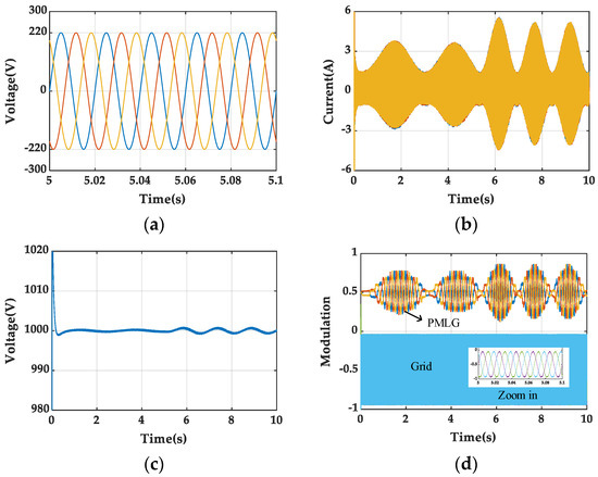
Figure 11.
Simulation of grid-connected multiport HWES: (a) three-phase voltage; (b) three-phase current; (c) dc bus voltage; (d) modulation.
Figure 12 shows the simulation waveform of an off-grid multiport HWES. As can be seen in Figure 12a, the average wave power captured by the PMLG is between 400 and 500 W, while the power of the load is 1000 W. At this time, the generator cannot meet the power demand of the load. Figure 12b shows the power output of the battery and supercapacitor, where positive values represent discharge, and negative values represent charge. It can be seen that the battery bears the difference between the load and the average power of the PMLG and is always in a discharge state, with power at about 500–600 W. In order to maintain the voltage stability of the dc bus, the supercapacitor assumes the power of the high-frequency part, which fluctuates repeatedly between −1000 W and 1000 W. Figure 12c shows the SOC state of the HESS. Figure 12d shows a modulated wave with the top half being the PMLG and the bottom half being the HESS and load.
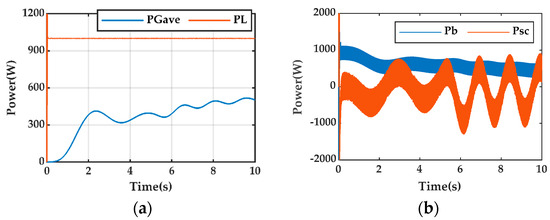
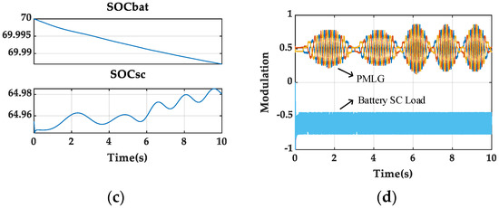
Figure 12.
Simulation of an off-grid multiport HWES: (a) power of load and average power of the PMLG; (b) power of the HESS; (c) SOC of the HESS; (d) modulation.
5. Experimental Verification
A scale-down multiport off-grid HWES experimental platform was built in the laboratory, as shown in Figure 13. The configuration in Figure 3b, along with the control strategy in Figure 6 and Figure 8, are applied here. The platform consists of a PMLG, a battery, a supercapacitor, a dc load and a nine-switch converter. The controller adopts rapid control prototyping (RCP) produced by the Yan Xu Company. The switching frequency is set to 10 kHz, and the parameters used for the experimental study are provided in Table 3.
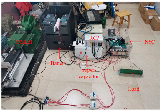
Figure 13.
Experimental platform.
Table 3.
Experimental parameters of off-grid HWES.
Figure 14 shows some experimental results recorded by the upper computer. In the laboratory, the induction motor and crank rods are used to simulate the action of the diffraction force, and a variable-frequency drive is used to simulate the change in the wave. For 0–5 s, the amplitude of the translator velocity is adjusted to 0.8 m/s, and the period is 1.7 s. For 5–10 s, the amplitude is 1 m/s, and the period is 1.3 s.
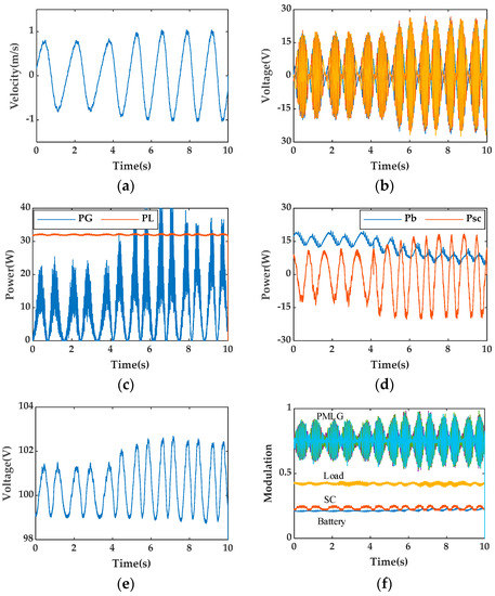
Figure 14.
Off-grid HWES experimental results: (a) velocity of translator; (b) back-EMF; (c) power of the load and PMLG; (d) power of the HESS; (e) dc bus voltage; (f) modulation.
It can be seen that the amplitude and frequency of the back-EMF of the PMLG also increase with the enhancement of the translator speed. Figure 14c shows the instantaneous power and load power waveforms of the PMLG. The load power is 32 W; 0–5 s is always higher than the instantaneous power of the PMLG. Although the power of the PMLG increases after 5 s, it is not enough to maintain the power demand of the load. Correspondingly, in Figure 14d, the battery has been discharged to make up the difference between the PMLG and the load power. As the average power of the PMLG increases, the battery power drops from 15 W to around 10 W. The power of the supercapacitor always jumps around zero, and with the increase in the PMLG power fluctuation, its fluctuation degree also increases. In Figure 14e, the voltage of the dc bus is stable at around 100 V. Although the voltage fluctuation degree increases at 5–10 s, it is still within the fluctuation range of 5%. The modulation wave results in Figure 14f correspond with those in Figure 12d, which verifies the reliable operation of the multiport off-grid HWES.
6. Discussion
In this section, other conventional HWESs are compared with the proposed multiport HWES. Table 4 summarizes the comparison between the conventional and multiport configurations discussed in Section 2, including the number of power devices, the control system, dc bus voltage, and MPPT functional implementation.
Table 4.
Comparison of various HWES configurations.
As can be seen from Table 4, the HWESs based on a nine-switch converter are lower than the systems proposed in other research with respect to the number of switches and diodes. In practical applications, this will reduce the number of driving circuits, buffer circuits and cooling circuits, thus significantly reducing the volume and cost of the converter system. In addition, the proposed system not only realizes the centralized control effect but also realizes decoupling, which facilitates the control of independent power flow and subsequent research on energy management strategies. Although the number of power devices in the multiport HWES is lower, they still enable flexible HESS configurations (up to three energy storage components) and MPPT functions, which are the same as a conventional common dc bus HWES.
Since the dc bus is shared between the upper and lower ports, the bus voltage of the multiport system is higher than that of other systems with the same specifications, and the larger dc-link capacitance needs to be selected. Due to the use of XOR logic, the switching frequency of the middle switches is relatively high. When the dead time is taken into account, some switching actions may disappear, which is also a drawback of the multiport HWES. In this paper, the energy management of the battery and supercapacitor is not reflected in the control strategy, which is also the direction of subsequent research.
7. Conclusions
In this paper, a nine-switch converter is used to replace the common dc bus structure of a conventional HWES. Without affecting the output performance, the power converter system is simplified by reducing the number of switches. The main contributions of this paper are as follows: (1) two multiport HWES configurations and their corresponding control strategies are proposed; (2) computer simulation verification is carried out for multiport grid-connected and off-grid HWESs; and (3) experimental verification is carried out for the multiport off-grid HWES. The results show that the application of a nine-switch converter to a DDWEC is feasible.
Author Contributions
Conceptualization and methodology, W.Y.; software and validation, R.M.; writing—original draft preparation, D.X.; writing—review and editing, L.H.; validation, S.W. All authors have read and agreed to the published version of the manuscript.
Funding
This research was funded by the National Natural Science Foundation of China, grant number 41876096, and the National Defense Science and Technology Key Laboratory Foundation of China, grant number 6142217190101.
Institutional Review Board Statement
Not applicable.
Informed Consent Statement
Not applicable.
Data Availability Statement
Not applicable.
Conflicts of Interest
The authors declare no conflict of interest.
References
- Sheng, W. Wave energy conversion and hydrodynamics modelling technologies: A review. Renew. Sustain. Energy Rev. 2019, 109, 482–498. [Google Scholar] [CrossRef]
- Farrok, O.; Ahmed, K.; Tahlil, A.D.; Farah, M.M.; Kiran, M.R.; Islam, M.R. Electrical Power Generation from the Oceanic Wave for Sustainable Advancement in Renewable Energy Technologies. Sustainability 2020, 12, 2178. [Google Scholar] [CrossRef]
- Mwasilu, F.; Jung, J. Potential for power generation from ocean wave renewable energy source: A comprehensive review on state-of-the-art technology and future prospects. IET Renew Power Gener. 2019, 13, 363–375. [Google Scholar] [CrossRef]
- Aderinto, T.; Li, H. Review on Power Performance and Efficiency of Wave Energy Converters. Energies 2019, 12, 4329. [Google Scholar] [CrossRef]
- Faiz, J.; Nematsaberi, A. Linear electrical generator topologies for direct-drive marine wave energy conversion—An overview. IET Renew. Power Gener. 2017, 11, 1163–1176. [Google Scholar] [CrossRef]
- Khatri, P.; Wang, X. Comprehensive review of a linear electrical generator for ocean wave energy conversion. IET Renew. Power Gener. 2020, 14, 949–958. [Google Scholar] [CrossRef]
- Wu, F.; Zhang, X.; Ju, P.; Sterling, M. Modeling and Control of AWS-Based Wave Energy Conversion System Integrated Into Power Grid. IEEE Trans. Power Syst. 2008, 23, 1196–1204. [Google Scholar] [CrossRef]
- Fang, H.; Zhang, X. Improvement of Low-Voltage Ride-Through Capability for Wave Energy Conversion System. IEEE Trans. Ind Electron. 2022, 69, 8123–8133. [Google Scholar] [CrossRef]
- Xiao, X.; Huang, X.; Kang, Q. A Hill-Climbing-Method-Based Maximum-Power-Point-Tracking Strategy for Direct-Drive Wave Energy Converters. IEEE Trans. Ind Electron. 2016, 63, 257–267. [Google Scholar] [CrossRef]
- Sousounis, M.C.; Gan, L.K.; Kiprakis, A.E.; Shek, J.K.H. Direct drive wave energy array with offshore energy storage supplying off-grid residential load. IET Renew. Power Gener. 2017, 11, 1081–1088. [Google Scholar] [CrossRef]
- Rasool, S.; Islam, M.R.; Muttaqi, K.M.; Sutanto, D. Coupled Modeling and Advanced Control for Smooth Operation of a Grid-Connected Linear Electric Generator Based Wave-to-Wire System. IEEE Trans. Ind. Appl. 2020, 56, 5575–5584. [Google Scholar] [CrossRef]
- Parwal, A.; Fregelius, M.; Temiz, I.; Göteman, M.; Oliveira, J.G.D.; Boström, C.; Leijon, M. Energy management for a grid-connected wave energy park through a hybrid energy storage system. Appl. Energy 2018, 231, 399–411. [Google Scholar] [CrossRef]
- Rasool, S.; Muttaqi, K.M.; Sutanto, D. A Multi-Filter Based Dynamic Power Sharing Control for a Hybrid Energy Storage System Integrated to a Wave Energy Converter for Output Power Smoothing. IEEE Trans. Sustain. Energy 2022, 13, 1693–1706. [Google Scholar] [CrossRef]
- Zhang, X.; Huang, L.; Wei, L.; Zhao, Y.; Liu, H.; Li, Y. Research on adaptive segmented control strategy used in direct-drive wave power generation systems. Energy Rep. 2022, 8, 8140–8150. [Google Scholar] [CrossRef]
- Nunez Forestieri, J.; Farasat, M. Integrative Sizing/Real-Time Energy Management of a Hybrid Supercapacitor/Undersea Energy Storage System for Grid Integration of Wave Energy Conversion Systems. IEEE J. Emerg. Sel. Top. Power Electron. 2020, 8, 3798–3810. [Google Scholar] [CrossRef]
- Nie, Z.; Xiao, X.; Kang, Q.; Aggarwal, R.; Zhang, H.; Yuan, W. SMES-Battery Energy Storage System for Conditioning Outputs From Direct Drive Linear Wave Energy Converters. IEEE Trans. Appl. Supercond. 2013, 23, 5000705. [Google Scholar] [CrossRef]
- Rasool, S.; Muttaqi, K.M.; Sutanto, D. A Novel Configuration of a Hybrid Offshore Wind-Wave Energy Conversion System and its Controls for a Remote Area Power Supply. IEEE Trans. Ind. Appl. 2022, 58, 7805–7817. [Google Scholar] [CrossRef]
- Rahman, M.A.; Islam, M.R.; Muttaqi, K.M.; Sutanto, D. Modeling and Design of a Multiport Magnetic Bus-Based Novel Wind-Wave Hybrid Ocean Energy Technology. IEEE Trans. Ind. Appl. 2021, 57, 5400–5410. [Google Scholar] [CrossRef]
- Rauf, A.M.; Khadkikar, V. Integrated Photovoltaic and Dynamic Voltage Restorer System Configuration. IEEE Trans. Sustain. Energy 2015, 6, 400–410. [Google Scholar] [CrossRef]
- Wang, K.; Zhang, J.; Pang, Y.; Xu, D.; Pan, L. Modeling of Nine-Switch-Converter Based on Virtual Leg and Its Application in DFIG Wind Generation System. IEEE Trans. Power Electron. 2020, 35, 7674–7688. [Google Scholar] [CrossRef]
- Bizhani, H.; Noroozian, R.; Muyeen, S.M.; Blaabjerg, F. Wind Farm Grid Integration Architecture using Unified Expandable Power Converter. IEEE Trans. Power Electron. 2019, 34, 3407–3417. [Google Scholar] [CrossRef]
- Zhang, Z.; Jin, C.; Tang, Y.; Dong, C.; Lin, P.; Mi, Y.; Wang, P. A Modulized Three-Port Interlinking Converter for Hybrid AC/DC/DS Microgrids Featured with a Decentralized Power Management Strategy. IEEE Trans. Ind. Electron. 2021, 68, 12430–12440. [Google Scholar] [CrossRef]
- Gao, F.; Zhang, L.; Li, D.; Loh, P.C.; Tang, Y.; Gao, H. Optimal Pulsewidth Modulation of Nine-Switch Converter. IEEE Trans. Power Electron. 2010, 25, 2331–2343. [Google Scholar] [CrossRef]
- Şahin, M.; Recep, T.E.U. Modelling of Supercapacitors Based on Simplified Equivalent Circuit. CPSS Trans. Power Electron. Appl. 2021, 6, 31–39. [Google Scholar] [CrossRef]
- Tremblay, O.; Dessaint, L.A.; Dekkiche, A.I. A Generic Battery Model for the Dynamic Simulation of Hybrid Electric Vehicles. In Proceedings of the 2007 IEEE Vehicle Power and Propulsion Conference (VPPC), Arlington, TX, USA, 9–12 September 2007; pp. 284–289. [Google Scholar] [CrossRef]
- Kang, Q.; Xiao, X.; Nie, Z.; Huang, L.; Sun, K. Design of Grid-connected Directly Driven Wave Power Generation System with Optimal Control of Output Power. In Proceedings of the 2013 15th European Conference on Power Electronics and Applications (EPE), Lille, France, 2–6 September 2013; pp. 1–8. [Google Scholar] [CrossRef]


Disclaimer/Publisher’s Note: The statements, opinions and data contained in all publications are solely those of the individual author(s) and contributor(s) and not of MDPI and/or the editor(s). MDPI and/or the editor(s) disclaim responsibility for any injury to people or property resulting from any ideas, methods, instructions or products referred to in the content. |
© 2023 by the authors. Licensee MDPI, Basel, Switzerland. This article is an open access article distributed under the terms and conditions of the Creative Commons Attribution (CC BY) license (https://creativecommons.org/licenses/by/4.0/).